EP4201761A1 - Grip grasping state determination device, determination method, and system including determination device - Google Patents
Grip grasping state determination device, determination method, and system including determination device Download PDFInfo
- Publication number
- EP4201761A1 EP4201761A1 EP22212698.9A EP22212698A EP4201761A1 EP 4201761 A1 EP4201761 A1 EP 4201761A1 EP 22212698 A EP22212698 A EP 22212698A EP 4201761 A1 EP4201761 A1 EP 4201761A1
- Authority
- EP
- European Patent Office
- Prior art keywords
- grip
- grasping state
- driver
- sensor
- vibration
- Prior art date
- Legal status (The legal status is an assumption and is not a legal conclusion. Google has not performed a legal analysis and makes no representation as to the accuracy of the status listed.)
- Granted
Links
Images





Classifications
-
- B—PERFORMING OPERATIONS; TRANSPORTING
- B60—VEHICLES IN GENERAL
- B60T—VEHICLE BRAKE CONTROL SYSTEMS OR PARTS THEREOF; BRAKE CONTROL SYSTEMS OR PARTS THEREOF, IN GENERAL; ARRANGEMENT OF BRAKING ELEMENTS ON VEHICLES IN GENERAL; PORTABLE DEVICES FOR PREVENTING UNWANTED MOVEMENT OF VEHICLES; VEHICLE MODIFICATIONS TO FACILITATE COOLING OF BRAKES
- B60T8/00—Arrangements for adjusting wheel-braking force to meet varying vehicular or ground-surface conditions, e.g. limiting or varying distribution of braking force
- B60T8/17—Using electrical or electronic regulation means to control braking
- B60T8/1701—Braking or traction control means specially adapted for particular types of vehicles
- B60T8/1706—Braking or traction control means specially adapted for particular types of vehicles for single-track vehicles, e.g. motorcycles
-
- B—PERFORMING OPERATIONS; TRANSPORTING
- B60—VEHICLES IN GENERAL
- B60W—CONJOINT CONTROL OF VEHICLE SUB-UNITS OF DIFFERENT TYPE OR DIFFERENT FUNCTION; CONTROL SYSTEMS SPECIALLY ADAPTED FOR HYBRID VEHICLES; ROAD VEHICLE DRIVE CONTROL SYSTEMS FOR PURPOSES NOT RELATED TO THE CONTROL OF A PARTICULAR SUB-UNIT
- B60W40/00—Estimation or calculation of non-directly measurable driving parameters for road vehicle drive control systems not related to the control of a particular sub unit, e.g. by using mathematical models
- B60W40/08—Estimation or calculation of non-directly measurable driving parameters for road vehicle drive control systems not related to the control of a particular sub unit, e.g. by using mathematical models related to drivers or passengers
-
- B—PERFORMING OPERATIONS; TRANSPORTING
- B60—VEHICLES IN GENERAL
- B60W—CONJOINT CONTROL OF VEHICLE SUB-UNITS OF DIFFERENT TYPE OR DIFFERENT FUNCTION; CONTROL SYSTEMS SPECIALLY ADAPTED FOR HYBRID VEHICLES; ROAD VEHICLE DRIVE CONTROL SYSTEMS FOR PURPOSES NOT RELATED TO THE CONTROL OF A PARTICULAR SUB-UNIT
- B60W50/00—Details of control systems for road vehicle drive control not related to the control of a particular sub-unit, e.g. process diagnostic or vehicle driver interfaces
- B60W50/08—Interaction between the driver and the control system
-
- B—PERFORMING OPERATIONS; TRANSPORTING
- B60—VEHICLES IN GENERAL
- B60W—CONJOINT CONTROL OF VEHICLE SUB-UNITS OF DIFFERENT TYPE OR DIFFERENT FUNCTION; CONTROL SYSTEMS SPECIALLY ADAPTED FOR HYBRID VEHICLES; ROAD VEHICLE DRIVE CONTROL SYSTEMS FOR PURPOSES NOT RELATED TO THE CONTROL OF A PARTICULAR SUB-UNIT
- B60W50/00—Details of control systems for road vehicle drive control not related to the control of a particular sub-unit, e.g. process diagnostic or vehicle driver interfaces
- B60W50/08—Interaction between the driver and the control system
- B60W50/14—Means for informing the driver, warning the driver or prompting a driver intervention
-
- B—PERFORMING OPERATIONS; TRANSPORTING
- B62—LAND VEHICLES FOR TRAVELLING OTHERWISE THAN ON RAILS
- B62J—CYCLE SADDLES OR SEATS; AUXILIARY DEVICES OR ACCESSORIES SPECIALLY ADAPTED TO CYCLES AND NOT OTHERWISE PROVIDED FOR, e.g. ARTICLE CARRIERS OR CYCLE PROTECTORS
- B62J27/00—Safety equipment
-
- B—PERFORMING OPERATIONS; TRANSPORTING
- B62—LAND VEHICLES FOR TRAVELLING OTHERWISE THAN ON RAILS
- B62J—CYCLE SADDLES OR SEATS; AUXILIARY DEVICES OR ACCESSORIES SPECIALLY ADAPTED TO CYCLES AND NOT OTHERWISE PROVIDED FOR, e.g. ARTICLE CARRIERS OR CYCLE PROTECTORS
- B62J45/00—Electrical equipment arrangements specially adapted for use as accessories on cycles, not otherwise provided for
- B62J45/40—Sensor arrangements; Mounting thereof
- B62J45/42—Sensor arrangements; Mounting thereof characterised by mounting
- B62J45/422—Sensor arrangements; Mounting thereof characterised by mounting on the handlebar
-
- B—PERFORMING OPERATIONS; TRANSPORTING
- B62—LAND VEHICLES FOR TRAVELLING OTHERWISE THAN ON RAILS
- B62K—CYCLES; CYCLE FRAMES; CYCLE STEERING DEVICES; RIDER-OPERATED TERMINAL CONTROLS SPECIALLY ADAPTED FOR CYCLES; CYCLE AXLE SUSPENSIONS; CYCLE SIDECARS, FORECARS, OR THE LIKE
- B62K21/00—Steering devices
- B62K21/26—Handlebar grips
-
- B—PERFORMING OPERATIONS; TRANSPORTING
- B62—LAND VEHICLES FOR TRAVELLING OTHERWISE THAN ON RAILS
- B62L—BRAKES SPECIALLY ADAPTED FOR CYCLES
- B62L3/00—Brake-actuating mechanisms; Arrangements thereof
-
- B—PERFORMING OPERATIONS; TRANSPORTING
- B60—VEHICLES IN GENERAL
- B60T—VEHICLE BRAKE CONTROL SYSTEMS OR PARTS THEREOF; BRAKE CONTROL SYSTEMS OR PARTS THEREOF, IN GENERAL; ARRANGEMENT OF BRAKING ELEMENTS ON VEHICLES IN GENERAL; PORTABLE DEVICES FOR PREVENTING UNWANTED MOVEMENT OF VEHICLES; VEHICLE MODIFICATIONS TO FACILITATE COOLING OF BRAKES
- B60T2260/00—Interaction of vehicle brake system with other systems
- B60T2260/02—Active Steering, Steer-by-Wire
-
- B—PERFORMING OPERATIONS; TRANSPORTING
- B60—VEHICLES IN GENERAL
- B60W—CONJOINT CONTROL OF VEHICLE SUB-UNITS OF DIFFERENT TYPE OR DIFFERENT FUNCTION; CONTROL SYSTEMS SPECIALLY ADAPTED FOR HYBRID VEHICLES; ROAD VEHICLE DRIVE CONTROL SYSTEMS FOR PURPOSES NOT RELATED TO THE CONTROL OF A PARTICULAR SUB-UNIT
- B60W50/00—Details of control systems for road vehicle drive control not related to the control of a particular sub-unit, e.g. process diagnostic or vehicle driver interfaces
- B60W50/08—Interaction between the driver and the control system
- B60W50/14—Means for informing the driver, warning the driver or prompting a driver intervention
- B60W2050/143—Alarm means
-
- B—PERFORMING OPERATIONS; TRANSPORTING
- B60—VEHICLES IN GENERAL
- B60W—CONJOINT CONTROL OF VEHICLE SUB-UNITS OF DIFFERENT TYPE OR DIFFERENT FUNCTION; CONTROL SYSTEMS SPECIALLY ADAPTED FOR HYBRID VEHICLES; ROAD VEHICLE DRIVE CONTROL SYSTEMS FOR PURPOSES NOT RELATED TO THE CONTROL OF A PARTICULAR SUB-UNIT
- B60W2300/00—Indexing codes relating to the type of vehicle
- B60W2300/36—Cycles; Motorcycles; Scooters
-
- B—PERFORMING OPERATIONS; TRANSPORTING
- B60—VEHICLES IN GENERAL
- B60W—CONJOINT CONTROL OF VEHICLE SUB-UNITS OF DIFFERENT TYPE OR DIFFERENT FUNCTION; CONTROL SYSTEMS SPECIALLY ADAPTED FOR HYBRID VEHICLES; ROAD VEHICLE DRIVE CONTROL SYSTEMS FOR PURPOSES NOT RELATED TO THE CONTROL OF A PARTICULAR SUB-UNIT
- B60W2540/00—Input parameters relating to occupants
- B60W2540/223—Posture, e.g. hand, foot, or seat position, turned or inclined
-
- B—PERFORMING OPERATIONS; TRANSPORTING
- B60—VEHICLES IN GENERAL
- B60W—CONJOINT CONTROL OF VEHICLE SUB-UNITS OF DIFFERENT TYPE OR DIFFERENT FUNCTION; CONTROL SYSTEMS SPECIALLY ADAPTED FOR HYBRID VEHICLES; ROAD VEHICLE DRIVE CONTROL SYSTEMS FOR PURPOSES NOT RELATED TO THE CONTROL OF A PARTICULAR SUB-UNIT
- B60W2710/00—Output or target parameters relating to a particular sub-units
- B60W2710/18—Braking system
-
- B—PERFORMING OPERATIONS; TRANSPORTING
- B60—VEHICLES IN GENERAL
- B60W—CONJOINT CONTROL OF VEHICLE SUB-UNITS OF DIFFERENT TYPE OR DIFFERENT FUNCTION; CONTROL SYSTEMS SPECIALLY ADAPTED FOR HYBRID VEHICLES; ROAD VEHICLE DRIVE CONTROL SYSTEMS FOR PURPOSES NOT RELATED TO THE CONTROL OF A PARTICULAR SUB-UNIT
- B60W2710/00—Output or target parameters relating to a particular sub-units
- B60W2710/20—Steering systems
-
- B—PERFORMING OPERATIONS; TRANSPORTING
- B62—LAND VEHICLES FOR TRAVELLING OTHERWISE THAN ON RAILS
- B62J—CYCLE SADDLES OR SEATS; AUXILIARY DEVICES OR ACCESSORIES SPECIALLY ADAPTED TO CYCLES AND NOT OTHERWISE PROVIDED FOR, e.g. ARTICLE CARRIERS OR CYCLE PROTECTORS
- B62J45/00—Electrical equipment arrangements specially adapted for use as accessories on cycles, not otherwise provided for
- B62J45/40—Sensor arrangements; Mounting thereof
- B62J45/41—Sensor arrangements; Mounting thereof characterised by the type of sensor
- B62J45/414—Acceleration sensors
-
- B—PERFORMING OPERATIONS; TRANSPORTING
- B62—LAND VEHICLES FOR TRAVELLING OTHERWISE THAN ON RAILS
- B62J—CYCLE SADDLES OR SEATS; AUXILIARY DEVICES OR ACCESSORIES SPECIALLY ADAPTED TO CYCLES AND NOT OTHERWISE PROVIDED FOR, e.g. ARTICLE CARRIERS OR CYCLE PROTECTORS
- B62J50/00—Arrangements specially adapted for use on cycles not provided for in main groups B62J1/00 - B62J45/00
- B62J50/20—Information-providing devices
- B62J50/21—Information-providing devices intended to provide information to rider or passenger
-
- B—PERFORMING OPERATIONS; TRANSPORTING
- B62—LAND VEHICLES FOR TRAVELLING OTHERWISE THAN ON RAILS
- B62K—CYCLES; CYCLE FRAMES; CYCLE STEERING DEVICES; RIDER-OPERATED TERMINAL CONTROLS SPECIALLY ADAPTED FOR CYCLES; CYCLE AXLE SUSPENSIONS; CYCLE SIDECARS, FORECARS, OR THE LIKE
- B62K21/00—Steering devices
- B62K21/08—Steering dampers
-
- B—PERFORMING OPERATIONS; TRANSPORTING
- B62—LAND VEHICLES FOR TRAVELLING OTHERWISE THAN ON RAILS
- B62K—CYCLES; CYCLE FRAMES; CYCLE STEERING DEVICES; RIDER-OPERATED TERMINAL CONTROLS SPECIALLY ADAPTED FOR CYCLES; CYCLE AXLE SUSPENSIONS; CYCLE SIDECARS, FORECARS, OR THE LIKE
- B62K23/00—Rider-operated controls specially adapted for cycles, i.e. means for initiating control operations, e.g. levers, grips
- B62K23/02—Rider-operated controls specially adapted for cycles, i.e. means for initiating control operations, e.g. levers, grips hand actuated
- B62K23/04—Twist grips
Definitions
- the present invention relates to: a determination device and a determination method for determining a grasping state of a grip that is attached to a driving operation handlebar for a driver who operates a two-wheeled motor vehicle; and a warning system, a power steering control system, and an automated emergency brake control system including the determination device.
- a pressure sensor that detects a pressure is provided to a grip, and the electronic control unit includes a control section that calculates any of a request value of drive power of the two-wheeled motor vehicle, a request value of a clutch connection state, and a request value of an operating pressure of a brake on the basis of the pressure detected by the pressure sensor and controls respective one of the drive power, the clutch connection state, and the operating pressure of the brake.
- the drive power or the like is controlled on the basis of a calculation result of the respective request value.
- a driver can control the desired drive power or the like without removing his/her fingers from the grip (for example, see JP2020-040542A ) .
- the accurate grasping state by the driver may not be determined depending on an arrangement position of the pressure sensor. That is, a pressure detection value may vary according to the driver's grip grasping habit or a way the driver grasps the grip.
- vibration generated by an engine may affect the detection value by the pressure sensor.
- the present invention has been made with the above-described problems as the background and therefore provides a determination device and a determination method capable of minimizing a possibility of an erroneous determination, which is caused by a way a driver grasps a grip and vibration of a vehicle, and accurately determining a grip grasping state of the driver.
- the present invention also provides a warning system, a power steering control system, and an automated emergency brake control system including the determination device.
- a grip grasping state determination device has: a grip sensor that is attached to a driving operation handlebar for a two-wheeled motor vehicle and detects vibration of a grip grasped by a driver of the two-wheeled motor vehicle; a storage section that stores a vibration pattern according to a grasping state of the grip by the driver; and a determination section that determines the grasping state of the grip by the driver on the basis of the vibration detected by the grip sensor and the vibration pattern.
- a warning system includes a warning transmitter that transmits a warning to a driver according to a determination result by a determination section.
- a power steering control system includes a steering controller that changes steering damping control at the time of executing automated emergency brake control for a two-wheeled motor vehicle according to a determination result by a determination section.
- An automated emergency brake control system includes an automated brake controller that changes brake control at the time of executing automated emergency brake control for a two-wheeled motor vehicle according to a determination result by a determination section.
- a grip gasping state determination method has: a storage step of storing a vibration pattern that corresponds to a grip grasping state by a driver of a two-wheeled motor vehicle; an acquisition step of acquiring a signal from a grip sensor that is attached to a driving operation handlebar and detects vibration of a grip; and a determination step of determining the grip grasping state by the driver on the basis of the vibration detected by the grip sensor and the vibration pattern.
- the grip grasping state is determined on the basis of the vibration of the grip and the vibration pattern corresponding to the grip grasping state, which is stored in advance. Therefore, it is possible to reduce a possibility of an erroneous determination, which is caused by a grip grasping position by the driver, the vibration from the engine, and the like and thereby accurately determine the grip grasping state of the driver.
- the device, the system, and the determination method according to the present invention are not limited to a case with such a configuration, such operation, and the like.
- the two-wheeled motor vehicle may be a scooter or an electric motorcycle.
- Fig. 1 is a view illustrating a mounted state of the grip grasping state determination device 1 according to a first embodiment of the present invention and a system including the same to the two-wheeled motor vehicle.
- the grip grasping state determination device 1 is mounted to at least a two-wheeled motor vehicle 100, and includes: a left grip sensor 11 that detects vibration of a left grip 31; a right grip sensor 12 that detects vibration of a right grip 32; and a processing unit 20 that is installed in a control panel 40.
- the left grip sensor 11 and the right grip sensor 12 will collectively be referred to as grip sensors 11, 12.
- the grip grasping state determination device 1 may selectively be provided with a joint sensor 13 that detects vibration of a connection section between a driver handlebar 30 and a steering shaft (not illustrated) for supporting the driver handlebar 30.
- the grip sensors 11, 12 are sensors that respectively detect the vibration of the grips 31, 32, and the sensors for detecting the vibration are of a contact type and a non-contact type.
- a contact type sensor a piezoelectric sensor of a type detecting acceleration is used.
- a non-contact type sensor a laser Doppler sensor of a type detecting a speed or a capacitance sensor of a type detecting displacement is used. Any of all of these sensors can be applied to the present invention.
- the acceleration detection sensor capable of covering a wide frequency range is further preferred.
- a grip sensor including a three-axis gyroscope sensor and a three-directional acceleration sensor is adopted.
- the joint sensor 13 preferably includes the three-axis gyroscope sensor and the three-directional acceleration sensor, and outputs detected inertia to the processing unit 20.
- Each of the grip sensors 11, 12 can communicate an electrical signal with the processing unit 20 by wired connection or wireless communication such as Bluetooth ® .
- the grip sensors 11, 12 are each attached to a grip position of the handlebar 30, for example.
- the grip sensors 11, 12 are each attached to an end portion of the handlebar 30.
- the end portion of the handlebar 30 is a portion where a vibration amplitude is the largest.
- the joint sensor 13 is attached to a connection section 33 between the handlebar 30 and a steering column. Vibration in this connection section 33 is not affected by the grip grasping state of the driver. Accordingly, in order to determine the grasping state of the grip by the driver, the vibration detected by the joint sensor 13 is used as a reference value, and thus detection accuracy of the vibration of the grip can be improved. As long as the connection section is not affected by the grip grasping state of the driver, the connection section does not have to be strictly the connection section between the handlebar 30 and the steering column. For example, in the case where the steering column is divided into two, a connection section between the handlebar 30 and each of two divided portions of the steering column is also included as the connection section in the present invention.
- the processing unit 20 includes an acquisition section 21, a calculation section 22, a determination section 23, a communication section 24, a machine learning section 25, and a storage section 26.
- the sections of the processing unit 20 may collectively be provided in a single casing or may separately be provided in multiple casings.
- the processing unit 20 is accommodated in the control panel 40.
- the processing unit 20 may be accommodated in a steering controller 60 or an automated brake controller 70, for example.
- the processing unit 20 may partially or entirely be constructed of a microcomputer, a microprocessor unit, or the like, may be constructed of one whose firmware and the like can be updated, or may be a program module or the like that is executed by a command from a CPU or the like, for example.
- the acquisition section 21 acquires, from the grip sensors 11, 12, measurement values of the vibration of the grips 31, 32. In addition, the acquisition section 21 acquires, from the joint sensor 13, a measurement value of the vibration of the connection section 33.
- the calculation section 22 plots the vibration-related measurement values, which are acquired from the grip sensors 11, 12, by time and generates a vibration pattern in a certain specified period.
- the specified period may be fixed or may be variable.
- the calculation section 22 plots the vibration measurement values, which are acquired from the joint sensor 13, by time and generates a vibration profile in a certain specified period.
- the calculation section 22 calculates displacement from time-series data of the acceleration, which is detected by the respective sensors, and generates a vibration pattern of time and displacement.
- the determination section 23 determines the grip grasping state by the driver on the basis of the vibration of the grip, which is acquired by the acquisition section 21, and the vibration pattern, which is stored in the storage section 26 in advance and corresponds to the grip grasping state of the driver.
- the vibration pattern which is stored in advance
- a grasping vibration pattern indicative of the state where the driver grasps the grip and a non-grasping vibration pattern indicative of a state where the driver does not grasp the grip may be prepared.
- the grip grasping state by the driver may be determined by comparing a current vibration pattern of the grip, which is generated by the calculation section 22, and these vibration patterns.
- a displacement threshold value may be calculated from the vibration pattern, which is stored in advance.
- the grip grasping state by the driver may be determined by comparing the displacement, which is calculated from the vibration of the grip acquired by the acquisition section 21, and the displacement threshold value.
- Figs. 5A and 5B illustrate the grasping vibration pattern ( Fig. 5A ) and the non-grasping vibration pattern ( Fig. 5B ) as examples.
- the plural vibration patterns may be prepared according to a travel state of the two-wheeled motor vehicle (during normal travel, during curve travel, during brake operation, during a clutch operation, or the like).
- the determination result includes any of determination results that the driver "grasps the grip” and "does not grasp the grip”.
- the communication section 24 acquires the determination result by the determination section 23 and sends the determination result to a warning transmitter 50, the steering controller 60, or the automated brake controller 70.
- the machine learning section 25 selects one of plural machine learning models, and machine-learns a grip grasping state determination model by using the selected machine learning model, grip grasping information, and the vibration measurement value from the grip sensor that corresponds to the grip grasping information.
- the above machine learning model may be any of models that can be used for machine learning of the grip grasping state determination model among the existing machine learning models.
- the machine learning model may be a calculation model using a classification method, such as logistic regression, a support vector machine, a random forest, or a neighborhood method, a neural network, a Bayesian network, or the like.
- a processing flow by the machine learning section 25 will be described below.
- the storage section 26 is a device for saving and storing data and programs, and at least stores a program that is executed by the calculation section 22, the measurement values by the various sensors, the vibration pattern, the machine learning model, and the like.
- the warning transmitter 50 which is illustrated in Fig. 2 , at least includes an acquisition section 51 and a warning control section 52.
- the acquisition section 51 receives the determination result by the determination section 23 from the communication section 24 and receives a signal from the automated brake controller 70.
- the warning control section 52 receives, from the automated brake controller 70, a signal indicating that emergency braking is currently actuated, and acquires, from the communication section 24, a determination result of a state where any of the grips 31, 32 is not grasped by the driver, the warning control section 52 executes control for transmitting a warning to the driver.
- the warning may be a warning that is visually transmitted to the driver or a warning that is transmitted by sound via the control panel 40.
- the steering controller 60 which is illustrated in Fig. 3 , at least includes an acquisition section 61 and a damping control section 62.
- the acquisition section 61 receives the determination result by the determination section 23 from the communication section 24 and receives the signal from the automated brake controller 70.
- the damping control section 62 receives, from the automated brake controller 70, the signal indicating that the emergency braking is currently actuated, and acquires, from the communication section 24, the determination result of the state where any of the grips 31, 32 is not grasped by the driver, the damping control section 62 changes steering damping control. More specifically, the damping control section 62 executes control for increasing steering torque. In this way, even in the state where the driver does not grasp the grip, it is possible to prevent a rapid change in steering by the emergency braking.
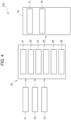
- the automated brake controller 70 which is illustrated in Fig. 4 , at least includes an acquisition section 71 and a brake control section 72.
- the acquisition section 71 receives the determination result by the determination section 23 from the communication section 24.
- the brake control section 72 changes brake control during execution of automated emergency brake control for the two-wheeled motor vehicle. More specifically, the brake control section 72 executes control for restricting brake torque to be lower than the brake torque during actuation of the normal emergency braking. In this way, even when the emergency braking is actuated in the state where the driver does not grasp the grip, it is possible to reduce a chance of a state where steering becomes unstable.
- the automated brake controller 70 may execute the control for restricting the brake torque only for a specified period in comparison with the brake torque during the actuation of the normal emergency braking. In this way, it is possible to provide the driver with a time margin for grasping the grip before the steering becomes unstable due to initiation of the actuation of the emergency braking.
- Fig. 6 is a chart illustrating an operation flow of the grip grasping state determination device 1 according to the embodiment of the present invention.
- step S101 the storage section 26 stores the vibration pattern that corresponds to the grasping state of the left grip 31 by the driver. More specifically, the calculation section 22 calculates the displacement on the basis of the time-series data of the acceleration of the left grip 31, which is acquired from the left grip sensor 11. Then, the storage section 26 stores the vibration pattern in which the displacement is plotted by time.
- the storage section 26 stores the vibration pattern that corresponds to the grasping state of the right grip 32 by the driver. More specifically, the calculation section 22 calculates the displacement on the basis of the time-series data of the acceleration of the right grip 32, which is acquired from the right grip sensor 12. Then, the storage section 26 stores the vibration pattern in which the displacement is plotted by time.
- step S102 the acquisition section 21 acquires the current vibration measurement value that is detected by the left grip sensor 11. More specifically, the acquisition section 21 acquires the measurement value of the acceleration of the left grip 31, which is acquired from the left grip sensor 11.
- the acquisition section 21 acquires the current vibration measurement value that is detected by the right grip sensor 12. More specifically, the acquisition section 21 acquires the measurement value of the acceleration of the right grip 32, which is acquired from the right grip sensor 12
- step S103 the determination section 23 determines the grip grasping state by the driver on the basis of the vibration detected by the grip sensors 11, 12 and the vibration patterns.
- the determination section 23 determines the grip grasping state by the driver by comparing the vibration pattern, which is stored in the storage section 26 in step S101, with the vibration measurement value, which is acquired by the acquisition section 21 in step S102. In the case where the acquired vibration matches or approximates the grasping vibration pattern, it is determined that the driver grasps the grip. On the other hand, in the case where acquired vibration matches or approximates the non-grasping vibration pattern, it is determined that the driver does not grasp the grip.
- the displacement threshold value may be calculated from the vibration pattern, which is stored in step S101. Then, in the case where the displacement, which is calculated from the time-series data of the acceleration acquired in step S102, falls below the displacement threshold value, that is, in the case where average displacement in the specified period is smaller than the displacement threshold value, it may be determined that the driver grasps the grip.
- step S104 the communication section 24 sends the determination result to each of the systems.
- the determination result is sent to the systems regardless of whether the driver grasps the grip.
- the determination result may be sent to the systems only in the case where it is determined that the driver does not grasp the grip.
- the grip grasping state determination device has: the grip sensor that is attached to the driving operation handlebar for the two-wheeled motor vehicle and detects the vibration of the grip grasped by the driver of the two-wheeled motor vehicle; the storage section that stores the vibration pattern corresponding to the grip grasping state by the driver; and the determination section that determines the grip grasping state by the driver on the basis of the vibration detected by the grip sensor and the vibration profile. Accordingly, it is possible to accurately determine the grasping state without relying on the grip grasping position by the driver, the driver's grip grasping habit, or the like. In addition, in order to determine the grasping state by the pressure sensor as in the related art, the pressure sensor has to be arranged accurately to the grip grasping position by the driver.
- the grip grasping state determination device uses the change in the vibration of the grip according to the grasping state by the driver, the arrangement position of the sensor is not limited to the grasping position by the driver. Therefore, it is possible to improve a degree of freedom in the arrangement of the sensor.
- Fig. 7 is a flowchart schematically illustrating an example of machine learning processing by the grip grasping state determination device according to the embodiment of the present invention.
- step S201 the grip grasping state determination device 1 acquires the grip grasping information and the vibration measurement value from the grip sensor, which corresponds to the grip grasping information. More specifically, the machine learning section 25 acquires the vibration measurement values that are accumulated in the storage section 26.
- the grip grasping information it may be determined that the grip is grasped when a throttle opening amount is detected, for example. This is because, in a state where the throttle opening amount is detected, it is understood that the driver at least grasps the grip on an accelerator side.
- step S202 the grip grasping state determination device 1 acquires the existing grip grasping state determination model. More specifically, the machine learning section 25 acquires the grip grasping state determination models that are accumulated in the storage section 26.
- the grip grasping state determination device 1 updates the grip grasping state determination model by using the grip grasping information and the vibration measurement value from the grip sensor (step S203). More specifically, the machine learning section 25 selects one of the plural machine learning models. Then, the machine learning section 25 machine-learns the grip grasping state determination model by using the selected machine learning model, the grip grasping information, and the vibration measurement value from the grip sensor, which corresponds to the grip grasping information.
- the grip grasping state determination device 1 calculates accuracy of the updated grip grasping state determination model (step S204) . More specifically, the machine learning section 25 inputs test input data to the new grip grasping state determination model, which is acquired by the machine learning, and compares an output value with test output data, so as to calculate the accuracy of the model.
- step S205/Y If the calculated value is equal to or larger than a threshold value (step S205/Y), the grip grasping state determination device 1 stores the updated grip grasping state determination model (step S206). More specifically, in the case where the calculated accuracy is equal to or higher than the threshold value, the machine learning section 25 stores the new grip grasping state determination model in the storage section 26. If the calculated value is smaller than the threshold value (step S205/N), the processing returns to step S203.
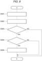
- Fig. 8 is a chart illustrating an operation flow of the warning system 110 according to the embodiment of the present invention.
- step S301 the acquisition section 51 acquires the determination result that is determined by the grip grasping state determination device 1. More specifically, the acquisition section 51 acquires the determination result that "the grip is grasped” or "the grip is not grasped". Such a determination result is the result of the determination that is made in step S103 of the operation flow by the grip grasping state determination device 1.
- step S302 the acquisition section 51 acquires, from the automated brake controller 70, information on whether the automated emergency brake control is currently executed.
- step S303 a determination section (not illustrated) determines whether the determination result, which is acquired from the processing unit 20, corresponds to that "the grip is not grasped". If the determination result corresponds to that "the grip is not grasped” (YES), the processing proceeds to step S304. If the determination result does not correspond to that "the grip is not grasped” (NO), the processing is terminated.
- step S304 the determination section (not illustrated) determines whether the signal acquired from the automated brake controller 70 corresponds to that "the emergency braking is currently actuated". If the determination result corresponds to that "the emergency braking is currently actuated” (YES), the processing proceeds to step S305. If the determination result does not correspond to that "the emergency braking is currently actuated” (NO), the processing is terminated.
- step S303 can be omitted.
- step S304 can be omitted.
- step S305 the warning control section 52 of the warning transmitter 50 executes the control for transmitting the warning to the driver.
- the warning may be transmitted to the driver via a screen of the control panel 40 or may be transmitted to the driver in the form of warning sound from a speaker, which is attached to a smart helmet, via the wireless communication.
- the warning system includes the warning transmitter that transmits the warning to the driver according to the determination result by the determination section of the grip grasping state determination device 1. Accordingly, in the case where the driver drives the two-wheeled motor vehicle with one hand at the time when the automated emergency braking is actuated, the warning is transmitted to the driver. As a result, the driver can grasp the grips with both of his/her hands on the basis of the warning.
- Fig. 9 is a chart illustrating an operation flow of the steering controller 60 according to the embodiment of the present invention.
- step S401 to step S404 are the same as step S301 to step S304 in the operation flow of the warning system 110. Thus, a description thereon will not be made.
- step S405 the steering controller 60 changes steering damping control. More specifically, the steering controller 60 executes control for increasing damping torque. As a result, rotational torque of the steering is increased. Thus, the handlebar is stabilized.
- the steering controller 60 changes the steering damping control during the execution of the automated emergency brake control for the two-wheeled motor vehicle according to the determination result by the determination section of the grip grasping state determination device 1. Accordingly, in the case where the driver drives the two-wheeled motor vehicle with one hand when the automated emergency braking is actuated, the steering controller executes the control for increasing the damping torque of the steering. Therefore, it is possible to stabilize a handlebar operation during the actuation of the automated emergency braking.
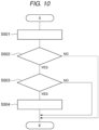
- Fig. 10 is a chart illustrating an operation flow of the automated emergency brake control system 130 according to the embodiment of the present invention.
- the automated emergency brake control system 130 executes the operation flow illustrated in Fig. 10 .
- step S501 the acquisition section 71 acquires the result of the determination that is made by the processing unit 20. More specifically, the acquisition section 71 acquires the determination result that "the grip is grasped” or "the grip is not grasped". Such a determination result is the result of the determination that is made in step S104 by the processing unit 20.
- step S502 the determination section (not illustrated) determines whether the determination result, which is acquired from the grip grasping state determination device 1, corresponds to that "the grip is not grasped". If the determination result corresponds to that "the grip is not grasped" (YES), the processing proceeds to step S503. If the determination result does not correspond to that "the grip is not grasped” (NO), the processing is terminated.
- step S503 the automated brake controller 70 determines whether the emergency braking is currently actuated. If the determination result corresponds to that "the emergency braking is currently actuated” (YES), the processing proceeds to step S504. If the determination result does not correspond to that "the emergency braking is currently actuated” (NO), the processing is terminated.
- step S502 can be omitted.
- step S504 the brake control section 72 changes the brake control. More specifically, the brake control section 72 executes control for reducing the brake torque to be lower than the brake torque during the actuation of the normal automated emergency braking. In further another example, the brake control section 72 can also execute control for reducing the brake torque only for the specified period in comparison with the brake torque during the execution of the normal emergency brake control.
- the automated brake controller changes the brake control during the execution of the automated emergency brake control for the two-wheeled motor vehicle according to the determination result by the determination section of the grip grasping state determination device. Accordingly, even in the case where the automated emergency braking is actuated when the driver drives the two-wheeled motor vehicle with one hand, the automated brake controller executes the control for reducing the brake torque to be lower than the brake torque during the actuation of the normal automated emergency braking. Therefore, it is possible to reduce a chance of the steering from becoming unstable.
- the automated brake controller can also execute the control for reducing the brake torque only for the specified period in comparison with that in the normal emergency brake control. In this way, it is possible to provide the driver with the time margin for grasping the grip before the steering becomes unstable.
Landscapes
- Engineering & Computer Science (AREA)
- Mechanical Engineering (AREA)
- Automation & Control Theory (AREA)
- Transportation (AREA)
- Human Computer Interaction (AREA)
- Physics & Mathematics (AREA)
- Mathematical Physics (AREA)
- Steering Devices For Bicycles And Motorcycles (AREA)
- Auxiliary Drives, Propulsion Controls, And Safety Devices (AREA)
- Regulating Braking Force (AREA)
- Automatic Cycles, And Cycles In General (AREA)
- Steering Controls (AREA)
Abstract
Description
- The present invention relates to: a determination device and a determination method for determining a grasping state of a grip that is attached to a driving operation handlebar for a driver who operates a two-wheeled motor vehicle; and a warning system, a power steering control system, and an automated emergency brake control system including the determination device.
- As a technique that is applied to a two-wheeled motor vehicle, the following electronic control unit has been known. A pressure sensor that detects a pressure is provided to a grip, and the electronic control unit includes a control section that calculates any of a request value of drive power of the two-wheeled motor vehicle, a request value of a clutch connection state, and a request value of an operating pressure of a brake on the basis of the pressure detected by the pressure sensor and controls respective one of the drive power, the clutch connection state, and the operating pressure of the brake.
- According to this electronic control unit, the drive power or the like is controlled on the basis of a calculation result of the respective request value. Thus, a driver can control the desired drive power or the like without removing his/her fingers from the grip (for example, see
JP2020-040542A - However, in the case where the grip grasping state of the driver is detected by the pressure sensor, the accurate grasping state by the driver may not be determined depending on an arrangement position of the pressure sensor. That is, a pressure detection value may vary according to the driver's grip grasping habit or a way the driver grasps the grip.
- In addition, vibration generated by an engine may affect the detection value by the pressure sensor.
- In order to solve these problems, it can be considered to arrange a plural pressure sensors to the grip. However, material cost and manufacturing cost for arranging the plural pressure sensors are increased as the number of the plural pressure sensors is increased.
- The present invention has been made with the above-described problems as the background and therefore provides a determination device and a determination method capable of minimizing a possibility of an erroneous determination, which is caused by a way a driver grasps a grip and vibration of a vehicle, and accurately determining a grip grasping state of the driver. The present invention also provides a warning system, a power steering control system, and an automated emergency brake control system including the determination device.
- A grip grasping state determination device according to the present invention has: a grip sensor that is attached to a driving operation handlebar for a two-wheeled motor vehicle and detects vibration of a grip grasped by a driver of the two-wheeled motor vehicle; a storage section that stores a vibration pattern according to a grasping state of the grip by the driver; and a determination section that determines the grasping state of the grip by the driver on the basis of the vibration detected by the grip sensor and the vibration pattern.
- A warning system according to the present invention includes a warning transmitter that transmits a warning to a driver according to a determination result by a determination section.
- A power steering control system according to the present invention includes a steering controller that changes steering damping control at the time of executing automated emergency brake control for a two-wheeled motor vehicle according to a determination result by a determination section. An automated emergency brake control system according to the present invention includes an automated brake controller that changes brake control at the time of executing automated emergency brake control for a two-wheeled motor vehicle according to a determination result by a determination section.
- A grip gasping state determination method according to the present invention has: a storage step of storing a vibration pattern that corresponds to a grip grasping state by a driver of a two-wheeled motor vehicle; an acquisition step of acquiring a signal from a grip sensor that is attached to a driving operation handlebar and detects vibration of a grip; and a determination step of determining the grip grasping state by the driver on the basis of the vibration detected by the grip sensor and the vibration pattern.
- In the grip grasping state determination device and the determination method according to the present invention, the grip grasping state is determined on the basis of the vibration of the grip and the vibration pattern corresponding to the grip grasping state, which is stored in advance. Therefore, it is possible to reduce a possibility of an erroneous determination, which is caused by a grip grasping position by the driver, the vibration from the engine, and the like and thereby accurately determine the grip grasping state of the driver.
-
-
Fig. 1 is a view illustrating an example of a mounted state of a grip grasping state determination device and a system including such a determination device to a two-wheeled motor vehicle or the like. -
Fig. 2 is a diagram illustrating an exemplary system configuration of a warning system. -
Fig. 3 is a diagram illustrating an exemplary system configuration of a power steering control system. -
Fig. 4 is a diagram illustrating an exemplary system configuration of an automated emergency brake control system. -
Figs. 5A and 5B are graphs illustrating examples of a vibration pattern. -
Fig. 6 is a chart illustrating an operation flow of the grip grasping state determination device. -
Fig. 7 is a chart illustrating an operation flow of a machine learning section. -
Fig. 8 is a chart illustrating an operation flow of the warning system. -
Fig. 9 is a chart illustrating an operation flow of the power steering control system. -
Fig. 10 is a chart illustrating an operation flow of the automated emergency brake control system. - A description will hereinafter be made on a grip grasping state determination device according to the present invention, a system including the determination device, and a determination method therefor with reference to the drawings.
- A configuration, operation, and the like, which will be described below, merely constitute one example. The device, the system, and the determination method according to the present invention are not limited to a case with such a configuration, such operation, and the like.
- For example, a description will hereinafter be made on a case where a two-wheeled motor vehicle is a motorcycle. However, the two-wheeled motor vehicle may be a scooter or an electric motorcycle.
- The same or similar description will appropriately be simplified or will not be made below. In the drawings, the same or similar portions will be denoted by the same reference sign. A detailed structure will appropriately be illustrated in a simplified manner or will not be illustrated.
- A description will be made on a configuration of a grip grasping state determination device 1.
-
Fig. 1 is a view illustrating a mounted state of the grip grasping state determination device 1 according to a first embodiment of the present invention and a system including the same to the two-wheeled motor vehicle. - As illustrated in
Fig. 1 , the grip grasping state determination device 1 is mounted to at least a two-wheeled motor vehicle 100, and includes: aleft grip sensor 11 that detects vibration of aleft grip 31; aright grip sensor 12 that detects vibration of aright grip 32; and aprocessing unit 20 that is installed in acontrol panel 40. Hereinafter, theleft grip sensor 11 and theright grip sensor 12 will collectively be referred to asgrip sensors joint sensor 13 that detects vibration of a connection section between adriver handlebar 30 and a steering shaft (not illustrated) for supporting thedriver handlebar 30. - The
grip sensors grips - Similar to the
grip sensors joint sensor 13 preferably includes the three-axis gyroscope sensor and the three-directional acceleration sensor, and outputs detected inertia to theprocessing unit 20. - Each of the
grip sensors processing unit 20 by wired connection or wireless communication such as Bluetooth®. - The
grip sensors handlebar 30, for example. Preferably, thegrip sensors handlebar 30. The end portion of thehandlebar 30 is a portion where a vibration amplitude is the largest. Thus, a change in the vibration caused by a grip grasping state of a driver can further easily be detected in such a portion. - The
joint sensor 13 is attached to aconnection section 33 between thehandlebar 30 and a steering column. Vibration in thisconnection section 33 is not affected by the grip grasping state of the driver. Accordingly, in order to determine the grasping state of the grip by the driver, the vibration detected by thejoint sensor 13 is used as a reference value, and thus detection accuracy of the vibration of the grip can be improved. As long as the connection section is not affected by the grip grasping state of the driver, the connection section does not have to be strictly the connection section between thehandlebar 30 and the steering column. For example, in the case where the steering column is divided into two, a connection section between thehandlebar 30 and each of two divided portions of the steering column is also included as the connection section in the present invention. - Next, a description will be made on a configuration of the
processing unit 20 in the grip grasping state determination device 1 and the system including such a device with reference toFig. 2 to Fig. 4 . - The
processing unit 20 includes anacquisition section 21, acalculation section 22, adetermination section 23, acommunication section 24, amachine learning section 25, and astorage section 26. The sections of theprocessing unit 20 may collectively be provided in a single casing or may separately be provided in multiple casings. InFig. 1 , theprocessing unit 20 is accommodated in thecontrol panel 40. However, theprocessing unit 20 may be accommodated in asteering controller 60 or anautomated brake controller 70, for example. Theprocessing unit 20 may partially or entirely be constructed of a microcomputer, a microprocessor unit, or the like, may be constructed of one whose firmware and the like can be updated, or may be a program module or the like that is executed by a command from a CPU or the like, for example. - The
acquisition section 21 acquires, from thegrip sensors grips acquisition section 21 acquires, from thejoint sensor 13, a measurement value of the vibration of theconnection section 33. - The
calculation section 22 plots the vibration-related measurement values, which are acquired from thegrip sensors - Similarly, the
calculation section 22 plots the vibration measurement values, which are acquired from thejoint sensor 13, by time and generates a vibration profile in a certain specified period. - In the case where each of the
grip sensors joint sensor 13 is the acceleration detection sensor, thecalculation section 22 calculates displacement from time-series data of the acceleration, which is detected by the respective sensors, and generates a vibration pattern of time and displacement. - The
determination section 23 determines the grip grasping state by the driver on the basis of the vibration of the grip, which is acquired by theacquisition section 21, and the vibration pattern, which is stored in thestorage section 26 in advance and corresponds to the grip grasping state of the driver. As the vibration pattern, which is stored in advance, a grasping vibration pattern indicative of the state where the driver grasps the grip and a non-grasping vibration pattern indicative of a state where the driver does not grasp the grip may be prepared. Then, the grip grasping state by the driver may be determined by comparing a current vibration pattern of the grip, which is generated by thecalculation section 22, and these vibration patterns. Alternatively, a displacement threshold value may be calculated from the vibration pattern, which is stored in advance. Then, the grip grasping state by the driver may be determined by comparing the displacement, which is calculated from the vibration of the grip acquired by theacquisition section 21, and the displacement threshold value.Figs. 5A and 5B illustrate the grasping vibration pattern (Fig. 5A ) and the non-grasping vibration pattern (Fig. 5B ) as examples. - The plural vibration patterns, each of which corresponds to the grasping state stored in advance, may be prepared according to a travel state of the two-wheeled motor vehicle (during normal travel, during curve travel, during brake operation, during a clutch operation, or the like).
- In addition, a frequency characteristic with the vibration measurement value, which is acquired from the
joint sensor 13, as an input value and the vibration measurement value, which is acquired from each of thegrip sensors - The determination result includes any of determination results that the driver "grasps the grip" and "does not grasp the grip".
- The
communication section 24 acquires the determination result by thedetermination section 23 and sends the determination result to awarning transmitter 50, the steeringcontroller 60, or theautomated brake controller 70. - The
machine learning section 25 selects one of plural machine learning models, and machine-learns a grip grasping state determination model by using the selected machine learning model, grip grasping information, and the vibration measurement value from the grip sensor that corresponds to the grip grasping information. - The above machine learning model may be any of models that can be used for machine learning of the grip grasping state determination model among the existing machine learning models. For example, the machine learning model may be a calculation model using a classification method, such as logistic regression, a support vector machine, a random forest, or a neighborhood method, a neural network, a Bayesian network, or the like. A processing flow by the
machine learning section 25 will be described below. - The
storage section 26 is a device for saving and storing data and programs, and at least stores a program that is executed by thecalculation section 22, the measurement values by the various sensors, the vibration pattern, the machine learning model, and the like. - The
warning transmitter 50, which is illustrated inFig. 2 , at least includes anacquisition section 51 and awarning control section 52. Theacquisition section 51 receives the determination result by thedetermination section 23 from thecommunication section 24 and receives a signal from theautomated brake controller 70. When thewarning control section 52 receives, from theautomated brake controller 70, a signal indicating that emergency braking is currently actuated, and acquires, from thecommunication section 24, a determination result of a state where any of thegrips warning control section 52 executes control for transmitting a warning to the driver. The warning may be a warning that is visually transmitted to the driver or a warning that is transmitted by sound via thecontrol panel 40. - The steering
controller 60, which is illustrated inFig. 3 , at least includes anacquisition section 61 and a dampingcontrol section 62. - The
acquisition section 61 receives the determination result by thedetermination section 23 from thecommunication section 24 and receives the signal from theautomated brake controller 70. When the dampingcontrol section 62 receives, from theautomated brake controller 70, the signal indicating that the emergency braking is currently actuated, and acquires, from thecommunication section 24, the determination result of the state where any of thegrips control section 62 changes steering damping control. More specifically, the dampingcontrol section 62 executes control for increasing steering torque. In this way, even in the state where the driver does not grasp the grip, it is possible to prevent a rapid change in steering by the emergency braking. - The
automated brake controller 70, which is illustrated inFig. 4 , at least includes anacquisition section 71 and abrake control section 72. - The
acquisition section 71 receives the determination result by thedetermination section 23 from thecommunication section 24. When theautomated brake controller 70 determines that the emergency braking is currently actuated, and thebrake control section 72 acquires, from thecommunication section 24, the determination result of the state where any of thegrips brake control section 72 changes brake control during execution of automated emergency brake control for the two-wheeled motor vehicle. More specifically, thebrake control section 72 executes control for restricting brake torque to be lower than the brake torque during actuation of the normal emergency braking. In this way, even when the emergency braking is actuated in the state where the driver does not grasp the grip, it is possible to reduce a chance of a state where steering becomes unstable. - As another example, the
automated brake controller 70 may execute the control for restricting the brake torque only for a specified period in comparison with the brake torque during the actuation of the normal emergency braking. In this way, it is possible to provide the driver with a time margin for grasping the grip before the steering becomes unstable due to initiation of the actuation of the emergency braking. - Next, a description will be made on operation of the grip grasping state determination device 1.
-
Fig. 6 is a chart illustrating an operation flow of the grip grasping state determination device 1 according to the embodiment of the present invention. - In step S101, the
storage section 26 stores the vibration pattern that corresponds to the grasping state of theleft grip 31 by the driver. More specifically, thecalculation section 22 calculates the displacement on the basis of the time-series data of the acceleration of theleft grip 31, which is acquired from theleft grip sensor 11. Then, thestorage section 26 stores the vibration pattern in which the displacement is plotted by time. - Similarly, the
storage section 26 stores the vibration pattern that corresponds to the grasping state of theright grip 32 by the driver. More specifically, thecalculation section 22 calculates the displacement on the basis of the time-series data of the acceleration of theright grip 32, which is acquired from theright grip sensor 12. Then, thestorage section 26 stores the vibration pattern in which the displacement is plotted by time. - In step S102, the
acquisition section 21 acquires the current vibration measurement value that is detected by theleft grip sensor 11. More specifically, theacquisition section 21 acquires the measurement value of the acceleration of theleft grip 31, which is acquired from theleft grip sensor 11. - Similarly, the
acquisition section 21 acquires the current vibration measurement value that is detected by theright grip sensor 12. More specifically, theacquisition section 21 acquires the measurement value of the acceleration of theright grip 32, which is acquired from theright grip sensor 12 - In step S103, the
determination section 23 determines the grip grasping state by the driver on the basis of the vibration detected by thegrip sensors - More specifically, the
determination section 23 determines the grip grasping state by the driver by comparing the vibration pattern, which is stored in thestorage section 26 in step S101, with the vibration measurement value, which is acquired by theacquisition section 21 in step S102. In the case where the acquired vibration matches or approximates the grasping vibration pattern, it is determined that the driver grasps the grip. On the other hand, in the case where acquired vibration matches or approximates the non-grasping vibration pattern, it is determined that the driver does not grasp the grip. - As another example, the displacement threshold value may be calculated from the vibration pattern, which is stored in step S101. Then, in the case where the displacement, which is calculated from the time-series data of the acceleration acquired in step S102, falls below the displacement threshold value, that is, in the case where average displacement in the specified period is smaller than the displacement threshold value, it may be determined that the driver grasps the grip.
- When the grip grasping state by the driver is determined in step S103, in step S104, the
communication section 24 sends the determination result to each of the systems. - In this example, the determination result is sent to the systems regardless of whether the driver grasps the grip. However, the determination result may be sent to the systems only in the case where it is determined that the driver does not grasp the grip.
- Next, a description will be made on effects of the grip grasping state determination device according to the embodiment.
- The grip grasping state determination device has: the grip sensor that is attached to the driving operation handlebar for the two-wheeled motor vehicle and detects the vibration of the grip grasped by the driver of the two-wheeled motor vehicle; the storage section that stores the vibration pattern corresponding to the grip grasping state by the driver; and the determination section that determines the grip grasping state by the driver on the basis of the vibration detected by the grip sensor and the vibration profile. Accordingly, it is possible to accurately determine the grasping state without relying on the grip grasping position by the driver, the driver's grip grasping habit, or the like. In addition, in order to determine the grasping state by the pressure sensor as in the related art, the pressure sensor has to be arranged accurately to the grip grasping position by the driver. However, since the grip grasping state determination device according to the present invention uses the change in the vibration of the grip according to the grasping state by the driver, the arrangement position of the sensor is not limited to the grasping position by the driver. Therefore, it is possible to improve a degree of freedom in the arrangement of the sensor.
- Next, a description will be made on operation of the machine learning section in the grip grasping state determination device with reference to
Fig. 7. Fig. 7 is a flowchart schematically illustrating an example of machine learning processing by the grip grasping state determination device according to the embodiment of the present invention. - In step S201, the grip grasping state determination device 1 acquires the grip grasping information and the vibration measurement value from the grip sensor, which corresponds to the grip grasping information. More specifically, the
machine learning section 25 acquires the vibration measurement values that are accumulated in thestorage section 26. In the grip grasping information, it may be determined that the grip is grasped when a throttle opening amount is detected, for example. This is because, in a state where the throttle opening amount is detected, it is understood that the driver at least grasps the grip on an accelerator side. - In step S202, the grip grasping state determination device 1 acquires the existing grip grasping state determination model. More specifically, the
machine learning section 25 acquires the grip grasping state determination models that are accumulated in thestorage section 26. - Next, the grip grasping state determination device 1 updates the grip grasping state determination model by using the grip grasping information and the vibration measurement value from the grip sensor (step S203). More specifically, the
machine learning section 25 selects one of the plural machine learning models. Then, themachine learning section 25 machine-learns the grip grasping state determination model by using the selected machine learning model, the grip grasping information, and the vibration measurement value from the grip sensor, which corresponds to the grip grasping information. - Next, the grip grasping state determination device 1 calculates accuracy of the updated grip grasping state determination model (step S204) . More specifically, the
machine learning section 25 inputs test input data to the new grip grasping state determination model, which is acquired by the machine learning, and compares an output value with test output data, so as to calculate the accuracy of the model. - If the calculated value is equal to or larger than a threshold value (step S205/Y), the grip grasping state determination device 1 stores the updated grip grasping state determination model (step S206). More specifically, in the case where the calculated accuracy is equal to or higher than the threshold value, the
machine learning section 25 stores the new grip grasping state determination model in thestorage section 26. If the calculated value is smaller than the threshold value (step S205/N), the processing returns to step S203. - A description will hereinafter be made on an operation flow of a warning system.
- A description will be made on operation of a
warning system 110 according to the embodiment. -
Fig. 8 is a chart illustrating an operation flow of thewarning system 110 according to the embodiment of the present invention. - In step S301, the
acquisition section 51 acquires the determination result that is determined by the grip grasping state determination device 1. More specifically, theacquisition section 51 acquires the determination result that "the grip is grasped" or "the grip is not grasped". Such a determination result is the result of the determination that is made in step S103 of the operation flow by the grip grasping state determination device 1. - Then, in step S302, the
acquisition section 51 acquires, from theautomated brake controller 70, information on whether the automated emergency brake control is currently executed. - In step S303, a determination section (not illustrated) determines whether the determination result, which is acquired from the
processing unit 20, corresponds to that "the grip is not grasped". If the determination result corresponds to that "the grip is not grasped" (YES), the processing proceeds to step S304. If the determination result does not correspond to that "the grip is not grasped" (NO), the processing is terminated. - In step S304, the determination section (not illustrated) determines whether the signal acquired from the
automated brake controller 70 corresponds to that "the emergency braking is currently actuated". If the determination result corresponds to that "the emergency braking is currently actuated" (YES), the processing proceeds to step S305. If the determination result does not correspond to that "the emergency braking is currently actuated" (NO), the processing is terminated. - Here, in the case where the determination result that the grip is not grasped is only acquired from the grip grasping state determination device 1 in step S301, step S303 can be omitted.
- Similarly, in the case where, in step S302, the signal is acquired from the
automated brake controller 70 only when the emergency braking is actuated, step S304 can be omitted. - In step S305, the
warning control section 52 of thewarning transmitter 50 executes the control for transmitting the warning to the driver. The warning may be transmitted to the driver via a screen of thecontrol panel 40 or may be transmitted to the driver in the form of warning sound from a speaker, which is attached to a smart helmet, via the wireless communication. - A description will be made on effects of the warning system.
- The warning system includes the warning transmitter that transmits the warning to the driver according to the determination result by the determination section of the grip grasping state determination device 1. Accordingly, in the case where the driver drives the two-wheeled motor vehicle with one hand at the time when the automated emergency braking is actuated, the warning is transmitted to the driver. As a result, the driver can grasp the grips with both of his/her hands on the basis of the warning.
- A description will be made on a power
steering control system 120. -
Fig. 9 is a chart illustrating an operation flow of thesteering controller 60 according to the embodiment of the present invention. - The power
steering control system 120 executes the operation flow illustrated inFig. 9 . Here, step S401 to step S404 are the same as step S301 to step S304 in the operation flow of thewarning system 110. Thus, a description thereon will not be made. - In step S405, the steering
controller 60 changes steering damping control. More specifically, the steeringcontroller 60 executes control for increasing damping torque. As a result, rotational torque of the steering is increased. Thus, the handlebar is stabilized. - A description will be made on effects of the power
steering control system 120. - According to the embodiment, the steering
controller 60 changes the steering damping control during the execution of the automated emergency brake control for the two-wheeled motor vehicle according to the determination result by the determination section of the grip grasping state determination device 1. Accordingly, in the case where the driver drives the two-wheeled motor vehicle with one hand when the automated emergency braking is actuated, the steering controller executes the control for increasing the damping torque of the steering. Therefore, it is possible to stabilize a handlebar operation during the actuation of the automated emergency braking. - A description will be made on operation of an automated emergency
brake control system 130. -
Fig. 10 is a chart illustrating an operation flow of the automated emergencybrake control system 130 according to the embodiment of the present invention. - The automated emergency
brake control system 130 executes the operation flow illustrated inFig. 10 . - In step S501, the
acquisition section 71 acquires the result of the determination that is made by theprocessing unit 20. More specifically, theacquisition section 71 acquires the determination result that "the grip is grasped" or "the grip is not grasped". Such a determination result is the result of the determination that is made in step S104 by theprocessing unit 20. - In step S502, the determination section (not illustrated) determines whether the determination result, which is acquired from the grip grasping state determination device 1, corresponds to that "the grip is not grasped". If the determination result corresponds to that "the grip is not grasped" (YES), the processing proceeds to step S503. If the determination result does not correspond to that "the grip is not grasped" (NO), the processing is terminated.
- In step S503, the
automated brake controller 70 determines whether the emergency braking is currently actuated. If the determination result corresponds to that "the emergency braking is currently actuated" (YES), the processing proceeds to step S504. If the determination result does not correspond to that "the emergency braking is currently actuated" (NO), the processing is terminated. Here, in the case where the determination result that "the grip is not grasped" is only acquired from the grip grasping state determination device 1 in step S501, step S502 can be omitted. - In step S504, the
brake control section 72 changes the brake control. More specifically, thebrake control section 72 executes control for reducing the brake torque to be lower than the brake torque during the actuation of the normal automated emergency braking. In further another example, thebrake control section 72 can also execute control for reducing the brake torque only for the specified period in comparison with the brake torque during the execution of the normal emergency brake control. - A description will be made on effects of the automated emergency
brake control system 130. - According to the embodiment, the automated brake controller changes the brake control during the execution of the automated emergency brake control for the two-wheeled motor vehicle according to the determination result by the determination section of the grip grasping state determination device. Accordingly, even in the case where the automated emergency braking is actuated when the driver drives the two-wheeled motor vehicle with one hand, the automated brake controller executes the control for reducing the brake torque to be lower than the brake torque during the actuation of the normal automated emergency braking. Therefore, it is possible to reduce a chance of the steering from becoming unstable. In addition, as another example, the automated brake controller can also execute the control for reducing the brake torque only for the specified period in comparison with that in the normal emergency brake control. In this way, it is possible to provide the driver with the time margin for grasping the grip before the steering becomes unstable.
- The description has been made so far on the embodiment of the present invention. However, the present invention is not limited to the description of the embodiment. For example, only a part of the embodiment may be implemented, or all or some of the parts of the embodiment may be combined.
Claims (11)
- A grip grasping state determination device comprising:a grip sensor that is attached to a driving operation handlebar of a two-wheeled motor vehicle and detects vibration of a grip grasped by a driver of the two-wheeled motor vehicle;a storage section that stores a vibration pattern corresponding to a grasping state of the grip by the driver; anda determination section that determines the grasping state of the grip by the driver on the basis of the vibration detected by the grip sensor and the vibration pattern.
- The grip grasping state determination device according to claim 1, wherein
the grip sensor is attached to an end portion of the driving operation handlebar. - The grip grasping state determination device according to claim 1 or 2 further comprising:
a joint sensor that detects vibration of a connection section between the driving operation handlebar and a steering column supporting the driving operation handlebar. - The grip grasping state determination device according to any one of claims 1 to 3, wherein
the grip sensor is a three-axis acceleration sensor. - The grip grasping state determination device according to claim 3, wherein
the joint sensor is a three-axis acceleration sensor. - The grip grasping state determination device according to any one of claims 1 to 5 further comprising:
a machine learning section that machine-learns a grip grasping state determination model with vibration as an input value on the basis of grip grasping information and the vibration from the grip sensor corresponding to the grip grasping information. - A warning system comprising:
a warning transmitter that transmits a warning to the driver according to a determination result by the determination section of the grip grasping state determination device according to any one of claims 1 to 6. - A power steering control system comprising:
a steering controller that changes steering damping control during execution of automated emergency brake control for the two-wheeled motor vehicle according to a determination result by the determination section of the grip grasping state determination device according to any one of claims 1 to 6. - An automated emergency brake control system comprising:
an automated brake controller that changes brake control during execution of automated emergency brake control for the two-wheeled motor vehicle according to a determination result by the determination section of the grip grasping state determination device according to any one of claims 1 to 6. - A grip grasping state determination method comprising:a storage step of storing a vibration pattern that corresponds to a grasping state of a grip by a driver of a two-wheeled motor vehicle;an acquisition step of acquiring a signal from a grip sensor that is attached to a driving operation handlebar and detects vibration of the grip; anda determination step of determining the grasping state of the grip by the driver on the basis of the vibration detected by the grip sensor and the vibration pattern.
- The grip grasping state determination method according to claim 10, whereinthe grip sensor is a three-axis acceleration sensor, andin the determination step, displacement is calculated from time-series data of acceleration that is detected by the three-axis acceleration sensor, and the grasping state of the grip is determined by comparing the displacement with a displacement threshold value that is acquired from the vibration pattern.
Applications Claiming Priority (1)
| Application Number | Priority Date | Filing Date | Title |
|---|---|---|---|
| JP2021211775A JP7816978B2 (en) | 2021-12-27 | 2021-12-27 | Grip state determination device, determination method, and system equipped with the determination device. |
Publications (2)
| Publication Number | Publication Date |
|---|---|
| EP4201761A1 true EP4201761A1 (en) | 2023-06-28 |
| EP4201761B1 EP4201761B1 (en) | 2025-08-27 |
Family
ID=84488721
Family Applications (1)
| Application Number | Title | Priority Date | Filing Date |
|---|---|---|---|
| EP22212698.9A Active EP4201761B1 (en) | 2021-12-27 | 2022-12-12 | Grip grasping state determination device, determination method, and system including determination device |
Country Status (2)
| Country | Link |
|---|---|
| EP (1) | EP4201761B1 (en) |
| JP (1) | JP7816978B2 (en) |
Citations (7)
| Publication number | Priority date | Publication date | Assignee | Title |
|---|---|---|---|---|
| DE102012221615A1 (en) * | 2012-11-27 | 2014-05-28 | Robert Bosch Gmbh | Method for performing brake operation in vehicle e.g. two-wheeler such as motorcycles, involves determining supporting force on left and right arms of driver by sensors on steering handle and automatically generating brake force |
| US20190135372A1 (en) * | 2017-11-06 | 2019-05-09 | Harley-Davidson Motor Company Group, LLC | Heated handgrips for a motorcycle |
| WO2019106073A1 (en) * | 2017-12-01 | 2019-06-06 | Continental Automotive Gmbh | Means for operating a motorcycle, system and method for operating a motorcycle |
| EP3613645A1 (en) * | 2017-04-17 | 2020-02-26 | Robert Bosch GmbH | Controller, control method, and brake system |
| JP2020040542A (en) | 2018-09-11 | 2020-03-19 | 株式会社ケーヒン | Electronic control device |
| DE102020203457A1 (en) * | 2019-03-28 | 2020-10-01 | Honda Motor Co., Ltd. | AUTOMATIC CONTROL DEVICE FOR A SEMI-DETACHED VEHICLE |
| DE112019007123T5 (en) * | 2019-03-29 | 2021-12-23 | Honda Motor Co., Ltd. | DRIVING ASSISTANT DEVICE FOR A SADDLE-TYPE VEHICLE |
Family Cites Families (5)
| Publication number | Priority date | Publication date | Assignee | Title |
|---|---|---|---|---|
| US20110063120A1 (en) * | 2009-09-15 | 2011-03-17 | Ronnie Ebner | Motorcycle grips with pressure sensors and alarm system |
| JP7168389B2 (en) * | 2018-09-19 | 2022-11-09 | ロベルト・ボッシュ・ゲゼルシャフト・ミト・ベシュレンクテル・ハフツング | Steering wheel excitation system and control method for steering wheel excitation system |
| JP7223573B2 (en) * | 2018-12-20 | 2023-02-16 | ロベルト・ボッシュ・ゲゼルシャフト・ミト・ベシュレンクテル・ハフツング | PROCESSING APPARATUS AND PROCESSING METHOD FOR RIDER ASSISTANCE SYSTEM FOR Saddle-riding VEHICLE, RIDER ASSISTANCE SYSTEM FOR Saddle-riding VEHICLE, AND Saddle-Riding Vehicle |
| CN113631470B (en) * | 2019-03-29 | 2023-02-03 | 本田技研工业株式会社 | Driving support device for saddle-ride type vehicle |
| CN112441168A (en) * | 2020-10-14 | 2021-03-05 | 上海理工大学 | Safe driving control method for electric vehicle |
-
2021
- 2021-12-27 JP JP2021211775A patent/JP7816978B2/en active Active
-
2022
- 2022-12-12 EP EP22212698.9A patent/EP4201761B1/en active Active
Patent Citations (7)
| Publication number | Priority date | Publication date | Assignee | Title |
|---|---|---|---|---|
| DE102012221615A1 (en) * | 2012-11-27 | 2014-05-28 | Robert Bosch Gmbh | Method for performing brake operation in vehicle e.g. two-wheeler such as motorcycles, involves determining supporting force on left and right arms of driver by sensors on steering handle and automatically generating brake force |
| EP3613645A1 (en) * | 2017-04-17 | 2020-02-26 | Robert Bosch GmbH | Controller, control method, and brake system |
| US20190135372A1 (en) * | 2017-11-06 | 2019-05-09 | Harley-Davidson Motor Company Group, LLC | Heated handgrips for a motorcycle |
| WO2019106073A1 (en) * | 2017-12-01 | 2019-06-06 | Continental Automotive Gmbh | Means for operating a motorcycle, system and method for operating a motorcycle |
| JP2020040542A (en) | 2018-09-11 | 2020-03-19 | 株式会社ケーヒン | Electronic control device |
| DE102020203457A1 (en) * | 2019-03-28 | 2020-10-01 | Honda Motor Co., Ltd. | AUTOMATIC CONTROL DEVICE FOR A SEMI-DETACHED VEHICLE |
| DE112019007123T5 (en) * | 2019-03-29 | 2021-12-23 | Honda Motor Co., Ltd. | DRIVING ASSISTANT DEVICE FOR A SADDLE-TYPE VEHICLE |
Also Published As
| Publication number | Publication date |
|---|---|
| EP4201761B1 (en) | 2025-08-27 |
| JP7816978B2 (en) | 2026-02-18 |
| JP2023096206A (en) | 2023-07-07 |
Similar Documents
| Publication | Publication Date | Title |
|---|---|---|
| EP1891490B1 (en) | Dialogue system | |
| KR102454611B1 (en) | How to monitor a car's drive-by-wire system | |
| CN105493165B (en) | Vehicle driving situation judging device and vehicle driving situation judging method | |
| EP2752347B1 (en) | Vehicular information-processing device and vehicular information-processing method | |
| JP7685375B2 (en) | SUSPENSION CONTROL DEVICE, SUSPENSION CONTROL METHOD, AND SUSPENSION CONTROL SYSTEM | |
| US20090066495A1 (en) | Methods and systems for determining driver efficiency and operating modes in a hybrid vehicle | |
| KR101313146B1 (en) | Adaptive cruise control system and the adaptive cruise control mehtod | |
| JP7066582B2 (en) | Judgment system, vehicle control system, vehicle, judgment method, and program | |
| US10845802B2 (en) | Method for operating a motor vehicle | |
| JP2008546109A (en) | Method and apparatus for detecting fatigue | |
| JP2019105909A (en) | Travel information storage method of lean type vehicle, travel information processing program, and travel information storage device | |
| KR20200007868A (en) | Driving support method and driving support device of vehicle | |
| KR20140114948A (en) | System and method of determining long term driving tendency of driver | |
| JP5125532B2 (en) | Data transmission device, electronic control unit and data transmission device | |
| WO2019168031A1 (en) | Road surface condition determination device | |
| US8918228B2 (en) | Vehicle behavior data storing apparatus | |
| EP4201761A1 (en) | Grip grasping state determination device, determination method, and system including determination device | |
| EP3347781B1 (en) | A verification module for verifying accuracy of a controller | |
| KR102888522B1 (en) | Vehicle steering control device based on dc motor torque control for driving safety | |
| JP2009001096A (en) | Driving support device, driving control device, and program | |
| US9758172B2 (en) | Status determination apparatus | |
| KR20240127120A (en) | System on chip, autonomous driving system including the same and operating method thereof | |
| KR102214892B1 (en) | System and method for determining a steering intervention by a driver | |
| JP4239809B2 (en) | Vehicle driving support device | |
| EP4331925A1 (en) | Travel control device |
Legal Events
| Date | Code | Title | Description |
|---|---|---|---|
| PUAI | Public reference made under article 153(3) epc to a published international application that has entered the european phase |
Free format text: ORIGINAL CODE: 0009012 |
|
| STAA | Information on the status of an ep patent application or granted ep patent |
Free format text: STATUS: THE APPLICATION HAS BEEN PUBLISHED |
|
| AK | Designated contracting states |
Kind code of ref document: A1 Designated state(s): AL AT BE BG CH CY CZ DE DK EE ES FI FR GB GR HR HU IE IS IT LI LT LU LV MC ME MK MT NL NO PL PT RO RS SE SI SK SM TR |
|
| STAA | Information on the status of an ep patent application or granted ep patent |
Free format text: STATUS: REQUEST FOR EXAMINATION WAS MADE |
|
| 17P | Request for examination filed |
Effective date: 20240102 |
|
| RBV | Designated contracting states (corrected) |
Designated state(s): AL AT BE BG CH CY CZ DE DK EE ES FI FR GB GR HR HU IE IS IT LI LT LU LV MC ME MK MT NL NO PL PT RO RS SE SI SK SM TR |
|
| RIC1 | Information provided on ipc code assigned before grant |
Ipc: B60W 50/08 20200101ALI20250224BHEP Ipc: B60W 40/08 20120101ALI20250224BHEP Ipc: B62K 23/04 20060101ALI20250224BHEP Ipc: B62J 45/422 20200101ALI20250224BHEP Ipc: B62J 45/411 20200101ALI20250224BHEP Ipc: B62D 5/04 20060101ALI20250224BHEP Ipc: B60W 50/14 20200101ALI20250224BHEP Ipc: B60T 8/17 20060101AFI20250224BHEP |
|
| GRAP | Despatch of communication of intention to grant a patent |
Free format text: ORIGINAL CODE: EPIDOSNIGR1 |
|
| STAA | Information on the status of an ep patent application or granted ep patent |
Free format text: STATUS: GRANT OF PATENT IS INTENDED |
|
| INTG | Intention to grant announced |
Effective date: 20250515 |
|
| GRAS | Grant fee paid |
Free format text: ORIGINAL CODE: EPIDOSNIGR3 |
|
| GRAA | (expected) grant |
Free format text: ORIGINAL CODE: 0009210 |
|
| STAA | Information on the status of an ep patent application or granted ep patent |
Free format text: STATUS: THE PATENT HAS BEEN GRANTED |
|
| AK | Designated contracting states |
Kind code of ref document: B1 Designated state(s): AL AT BE BG CH CY CZ DE DK EE ES FI FR GB GR HR HU IE IS IT LI LT LU LV MC ME MK MT NL NO PL PT RO RS SE SI SK SM TR |
|
| REG | Reference to a national code |
Ref country code: CH Ref legal event code: EP |
|
| REG | Reference to a national code |
Ref country code: DE Ref legal event code: R096 Ref document number: 602022020168 Country of ref document: DE |
|
| REG | Reference to a national code |
Ref country code: IE Ref legal event code: FG4D |
|
| REG | Reference to a national code |
Ref country code: NL Ref legal event code: MP Effective date: 20250827 |
|
| PG25 | Lapsed in a contracting state [announced via postgrant information from national office to epo] |
Ref country code: IS Free format text: LAPSE BECAUSE OF FAILURE TO SUBMIT A TRANSLATION OF THE DESCRIPTION OR TO PAY THE FEE WITHIN THE PRESCRIBED TIME-LIMIT Effective date: 20251227 |
|
| PG25 | Lapsed in a contracting state [announced via postgrant information from national office to epo] |
Ref country code: NO Free format text: LAPSE BECAUSE OF FAILURE TO SUBMIT A TRANSLATION OF THE DESCRIPTION OR TO PAY THE FEE WITHIN THE PRESCRIBED TIME-LIMIT Effective date: 20251127 |
|
| REG | Reference to a national code |
Ref country code: LT Ref legal event code: MG9D |
|
| PG25 | Lapsed in a contracting state [announced via postgrant information from national office to epo] |
Ref country code: PT Free format text: LAPSE BECAUSE OF FAILURE TO SUBMIT A TRANSLATION OF THE DESCRIPTION OR TO PAY THE FEE WITHIN THE PRESCRIBED TIME-LIMIT Effective date: 20251229 |
|
| PG25 | Lapsed in a contracting state [announced via postgrant information from national office to epo] |
Ref country code: FI Free format text: LAPSE BECAUSE OF FAILURE TO SUBMIT A TRANSLATION OF THE DESCRIPTION OR TO PAY THE FEE WITHIN THE PRESCRIBED TIME-LIMIT Effective date: 20250827 |
|
| PG25 | Lapsed in a contracting state [announced via postgrant information from national office to epo] |
Ref country code: HR Free format text: LAPSE BECAUSE OF FAILURE TO SUBMIT A TRANSLATION OF THE DESCRIPTION OR TO PAY THE FEE WITHIN THE PRESCRIBED TIME-LIMIT Effective date: 20250827 Ref country code: NL Free format text: LAPSE BECAUSE OF FAILURE TO SUBMIT A TRANSLATION OF THE DESCRIPTION OR TO PAY THE FEE WITHIN THE PRESCRIBED TIME-LIMIT Effective date: 20250827 |
|
| PG25 | Lapsed in a contracting state [announced via postgrant information from national office to epo] |
Ref country code: GR Free format text: LAPSE BECAUSE OF FAILURE TO SUBMIT A TRANSLATION OF THE DESCRIPTION OR TO PAY THE FEE WITHIN THE PRESCRIBED TIME-LIMIT Effective date: 20251128 |
|
| PG25 | Lapsed in a contracting state [announced via postgrant information from national office to epo] |
Ref country code: SE Free format text: LAPSE BECAUSE OF FAILURE TO SUBMIT A TRANSLATION OF THE DESCRIPTION OR TO PAY THE FEE WITHIN THE PRESCRIBED TIME-LIMIT Effective date: 20250827 |
|
| PG25 | Lapsed in a contracting state [announced via postgrant information from national office to epo] |
Ref country code: LV Free format text: LAPSE BECAUSE OF FAILURE TO SUBMIT A TRANSLATION OF THE DESCRIPTION OR TO PAY THE FEE WITHIN THE PRESCRIBED TIME-LIMIT Effective date: 20250827 |
|
| PG25 | Lapsed in a contracting state [announced via postgrant information from national office to epo] |
Ref country code: BG Free format text: LAPSE BECAUSE OF FAILURE TO SUBMIT A TRANSLATION OF THE DESCRIPTION OR TO PAY THE FEE WITHIN THE PRESCRIBED TIME-LIMIT Effective date: 20250827 Ref country code: PL Free format text: LAPSE BECAUSE OF FAILURE TO SUBMIT A TRANSLATION OF THE DESCRIPTION OR TO PAY THE FEE WITHIN THE PRESCRIBED TIME-LIMIT Effective date: 20250827 |
|
| PG25 | Lapsed in a contracting state [announced via postgrant information from national office to epo] |
Ref country code: RS Free format text: LAPSE BECAUSE OF FAILURE TO SUBMIT A TRANSLATION OF THE DESCRIPTION OR TO PAY THE FEE WITHIN THE PRESCRIBED TIME-LIMIT Effective date: 20251127 |
|
| PG25 | Lapsed in a contracting state [announced via postgrant information from national office to epo] |
Ref country code: ES Free format text: LAPSE BECAUSE OF FAILURE TO SUBMIT A TRANSLATION OF THE DESCRIPTION OR TO PAY THE FEE WITHIN THE PRESCRIBED TIME-LIMIT Effective date: 20250827 |
|
| REG | Reference to a national code |
Ref country code: AT Ref legal event code: MK05 Ref document number: 1829677 Country of ref document: AT Kind code of ref document: T Effective date: 20250827 |
|
| PG25 | Lapsed in a contracting state [announced via postgrant information from national office to epo] |
Ref country code: RO Free format text: LAPSE BECAUSE OF FAILURE TO SUBMIT A TRANSLATION OF THE DESCRIPTION OR TO PAY THE FEE WITHIN THE PRESCRIBED TIME-LIMIT Effective date: 20250827 |
|
| PG25 | Lapsed in a contracting state [announced via postgrant information from national office to epo] |
Ref country code: SM Free format text: LAPSE BECAUSE OF FAILURE TO SUBMIT A TRANSLATION OF THE DESCRIPTION OR TO PAY THE FEE WITHIN THE PRESCRIBED TIME-LIMIT Effective date: 20250827 |
|
| PG25 | Lapsed in a contracting state [announced via postgrant information from national office to epo] |
Ref country code: DK Free format text: LAPSE BECAUSE OF FAILURE TO SUBMIT A TRANSLATION OF THE DESCRIPTION OR TO PAY THE FEE WITHIN THE PRESCRIBED TIME-LIMIT Effective date: 20250827 |
|
| PGFP | Annual fee paid to national office [announced via postgrant information from national office to epo] |
Ref country code: DE Payment date: 20260223 Year of fee payment: 4 |
|
| PG25 | Lapsed in a contracting state [announced via postgrant information from national office to epo] |
Ref country code: AT Free format text: LAPSE BECAUSE OF FAILURE TO SUBMIT A TRANSLATION OF THE DESCRIPTION OR TO PAY THE FEE WITHIN THE PRESCRIBED TIME-LIMIT Effective date: 20250827 |
|
| PGFP | Annual fee paid to national office [announced via postgrant information from national office to epo] |
Ref country code: IT Payment date: 20251231 Year of fee payment: 4 |
|
| PG25 | Lapsed in a contracting state [announced via postgrant information from national office to epo] |
Ref country code: CZ Free format text: LAPSE BECAUSE OF FAILURE TO SUBMIT A TRANSLATION OF THE DESCRIPTION OR TO PAY THE FEE WITHIN THE PRESCRIBED TIME-LIMIT Effective date: 20250827 |
|
| PG25 | Lapsed in a contracting state [announced via postgrant information from national office to epo] |
Ref country code: EE Free format text: LAPSE BECAUSE OF FAILURE TO SUBMIT A TRANSLATION OF THE DESCRIPTION OR TO PAY THE FEE WITHIN THE PRESCRIBED TIME-LIMIT Effective date: 20250827 Ref country code: SK Free format text: LAPSE BECAUSE OF FAILURE TO SUBMIT A TRANSLATION OF THE DESCRIPTION OR TO PAY THE FEE WITHIN THE PRESCRIBED TIME-LIMIT Effective date: 20250827 |