EP4201720A1 - Vehicle - Google Patents
Vehicle Download PDFInfo
- Publication number
- EP4201720A1 EP4201720A1 EP22213425.6A EP22213425A EP4201720A1 EP 4201720 A1 EP4201720 A1 EP 4201720A1 EP 22213425 A EP22213425 A EP 22213425A EP 4201720 A1 EP4201720 A1 EP 4201720A1
- Authority
- EP
- European Patent Office
- Prior art keywords
- vehicle
- drive motor
- pair
- frame
- power transmission
- Prior art date
- Legal status (The legal status is an assumption and is not a legal conclusion. Google has not performed a legal analysis and makes no representation as to the accuracy of the status listed.)
- Granted
Links
Images







Classifications
-
- B—PERFORMING OPERATIONS; TRANSPORTING
- B62—LAND VEHICLES FOR TRAVELLING OTHERWISE THAN ON RAILS
- B62M—RIDER PROPULSION OF WHEELED VEHICLES OR SLEDGES; POWERED PROPULSION OF SLEDGES OR SINGLE-TRACK CYCLES; TRANSMISSIONS SPECIALLY ADAPTED FOR SUCH VEHICLES
- B62M7/00—Motorcycles characterised by position of motor or engine
- B62M7/02—Motorcycles characterised by position of motor or engine with engine between front and rear wheels
-
- B—PERFORMING OPERATIONS; TRANSPORTING
- B60—VEHICLES IN GENERAL
- B60K—ARRANGEMENT OR MOUNTING OF PROPULSION UNITS OR OF TRANSMISSIONS IN VEHICLES; ARRANGEMENT OR MOUNTING OF PLURAL DIVERSE PRIME-MOVERS IN VEHICLES; AUXILIARY DRIVES FOR VEHICLES; INSTRUMENTATION OR DASHBOARDS FOR VEHICLES; ARRANGEMENTS IN CONNECTION WITH COOLING, AIR INTAKE, GAS EXHAUST OR FUEL SUPPLY OF PROPULSION UNITS IN VEHICLES
- B60K1/00—Arrangement or mounting of electrical propulsion units
-
- B—PERFORMING OPERATIONS; TRANSPORTING
- B60—VEHICLES IN GENERAL
- B60K—ARRANGEMENT OR MOUNTING OF PROPULSION UNITS OR OF TRANSMISSIONS IN VEHICLES; ARRANGEMENT OR MOUNTING OF PLURAL DIVERSE PRIME-MOVERS IN VEHICLES; AUXILIARY DRIVES FOR VEHICLES; INSTRUMENTATION OR DASHBOARDS FOR VEHICLES; ARRANGEMENTS IN CONNECTION WITH COOLING, AIR INTAKE, GAS EXHAUST OR FUEL SUPPLY OF PROPULSION UNITS IN VEHICLES
- B60K17/00—Arrangement or mounting of transmissions in vehicles
- B60K17/04—Arrangement or mounting of transmissions in vehicles characterised by arrangement, location or kind of gearing
-
- B—PERFORMING OPERATIONS; TRANSPORTING
- B62—LAND VEHICLES FOR TRAVELLING OTHERWISE THAN ON RAILS
- B62J—CYCLE SADDLES OR SEATS; AUXILIARY DEVICES OR ACCESSORIES SPECIALLY ADAPTED TO CYCLES AND NOT OTHERWISE PROVIDED FOR, e.g. ARTICLE CARRIERS OR CYCLE PROTECTORS
- B62J43/00—Arrangements of batteries
- B62J43/10—Arrangements of batteries for propulsion
- B62J43/16—Arrangements of batteries for propulsion on motorcycles or the like
-
- B—PERFORMING OPERATIONS; TRANSPORTING
- B62—LAND VEHICLES FOR TRAVELLING OTHERWISE THAN ON RAILS
- B62J—CYCLE SADDLES OR SEATS; AUXILIARY DEVICES OR ACCESSORIES SPECIALLY ADAPTED TO CYCLES AND NOT OTHERWISE PROVIDED FOR, e.g. ARTICLE CARRIERS OR CYCLE PROTECTORS
- B62J43/00—Arrangements of batteries
- B62J43/20—Arrangements of batteries characterised by the mounting
-
- B—PERFORMING OPERATIONS; TRANSPORTING
- B62—LAND VEHICLES FOR TRAVELLING OTHERWISE THAN ON RAILS
- B62K—CYCLES; CYCLE FRAMES; CYCLE STEERING DEVICES; RIDER-OPERATED TERMINAL CONTROLS SPECIALLY ADAPTED FOR CYCLES; CYCLE AXLE SUSPENSIONS; CYCLE SIDECARS, FORECARS, OR THE LIKE
- B62K5/00—Cycles with handlebars, equipped with three or more main road wheels
- B62K5/01—Motorcycles with four or more wheels
-
- B—PERFORMING OPERATIONS; TRANSPORTING
- B62—LAND VEHICLES FOR TRAVELLING OTHERWISE THAN ON RAILS
- B62M—RIDER PROPULSION OF WHEELED VEHICLES OR SLEDGES; POWERED PROPULSION OF SLEDGES OR SINGLE-TRACK CYCLES; TRANSMISSIONS SPECIALLY ADAPTED FOR SUCH VEHICLES
- B62M9/00—Transmissions characterised by use of an endless chain, belt, or the like
- B62M9/04—Transmissions characterised by use of an endless chain, belt, or the like of changeable ratio
- B62M9/06—Transmissions characterised by use of an endless chain, belt, or the like of changeable ratio using a single chain, belt, or the like
-
- B—PERFORMING OPERATIONS; TRANSPORTING
- B60—VEHICLES IN GENERAL
- B60K—ARRANGEMENT OR MOUNTING OF PROPULSION UNITS OR OF TRANSMISSIONS IN VEHICLES; ARRANGEMENT OR MOUNTING OF PLURAL DIVERSE PRIME-MOVERS IN VEHICLES; AUXILIARY DRIVES FOR VEHICLES; INSTRUMENTATION OR DASHBOARDS FOR VEHICLES; ARRANGEMENTS IN CONNECTION WITH COOLING, AIR INTAKE, GAS EXHAUST OR FUEL SUPPLY OF PROPULSION UNITS IN VEHICLES
- B60K1/00—Arrangement or mounting of electrical propulsion units
- B60K2001/001—Arrangement or mounting of electrical propulsion units one motor mounted on a propulsion axle for rotating right and left wheels of this axle
-
- B—PERFORMING OPERATIONS; TRANSPORTING
- B60—VEHICLES IN GENERAL
- B60K—ARRANGEMENT OR MOUNTING OF PROPULSION UNITS OR OF TRANSMISSIONS IN VEHICLES; ARRANGEMENT OR MOUNTING OF PLURAL DIVERSE PRIME-MOVERS IN VEHICLES; AUXILIARY DRIVES FOR VEHICLES; INSTRUMENTATION OR DASHBOARDS FOR VEHICLES; ARRANGEMENTS IN CONNECTION WITH COOLING, AIR INTAKE, GAS EXHAUST OR FUEL SUPPLY OF PROPULSION UNITS IN VEHICLES
- B60K1/00—Arrangement or mounting of electrical propulsion units
- B60K1/04—Arrangement or mounting of electrical propulsion units of the electric storage means for propulsion
- B60K2001/0405—Arrangement or mounting of electrical propulsion units of the electric storage means for propulsion characterised by their position
-
- B—PERFORMING OPERATIONS; TRANSPORTING
- B60—VEHICLES IN GENERAL
- B60K—ARRANGEMENT OR MOUNTING OF PROPULSION UNITS OR OF TRANSMISSIONS IN VEHICLES; ARRANGEMENT OR MOUNTING OF PLURAL DIVERSE PRIME-MOVERS IN VEHICLES; AUXILIARY DRIVES FOR VEHICLES; INSTRUMENTATION OR DASHBOARDS FOR VEHICLES; ARRANGEMENTS IN CONNECTION WITH COOLING, AIR INTAKE, GAS EXHAUST OR FUEL SUPPLY OF PROPULSION UNITS IN VEHICLES
- B60K1/00—Arrangement or mounting of electrical propulsion units
- B60K1/04—Arrangement or mounting of electrical propulsion units of the electric storage means for propulsion
- B60K2001/0405—Arrangement or mounting of electrical propulsion units of the electric storage means for propulsion characterised by their position
- B60K2001/0411—Arrangement in the front part of the vehicle
-
- B—PERFORMING OPERATIONS; TRANSPORTING
- B60—VEHICLES IN GENERAL
- B60Y—INDEXING SCHEME RELATING TO ASPECTS CROSS-CUTTING VEHICLE TECHNOLOGY
- B60Y2200/00—Type of vehicle
- B60Y2200/10—Road Vehicles
- B60Y2200/12—Motorcycles, Trikes; Quads; Scooters
- B60Y2200/124—Buggies, Quads
-
- B—PERFORMING OPERATIONS; TRANSPORTING
- B60—VEHICLES IN GENERAL
- B60Y—INDEXING SCHEME RELATING TO ASPECTS CROSS-CUTTING VEHICLE TECHNOLOGY
- B60Y2200/00—Type of vehicle
- B60Y2200/90—Vehicles comprising electric prime movers
- B60Y2200/91—Electric vehicles
Definitions
- the present invention relates to vehicles, and more specifically to electric ATVs (All Terrain Vehicles) and the like.
- JP 5509811 B discloses an electric rough terrain vehicle which is pertinent to conventional techniques of this kind.
- the vehicle includes a steering shaft which is supported pivotably at a front portion of a vehicle frame; a left-right pair of front wheels steered by means of the steering shaft; a left-right pair of swing arms supported pivotably by the vehicle frame; a left-right pair of rear wheels supported on their shafts by the swing arms; a left-right pair of electric motors disposed between the left and right front wheels for driving the left and right front wheels respectively; a left-right pair of electric motors disposed between the left and right rear wheels for driving the left and right rear wheels respectively; and a battery disposed between the front and the rear wheels.
- JP 4214759 B discloses a four-wheeled electric rough terrain vehicle.
- the vehicle includes an electric motor disposed at a position near a rear portion of a body frame; a pair of rear wheels to which an output from the electric motor is transmitted via a gear case; a plurality of batteries provided in line in a fore-aft direction at a generally intermediate portion of the body frame; and a controller disposed ahead of the batteries.
- JP 5509811 B the electric motors which drive the rear wheels are disposed between the pair of swing arms, that is, layout of the electric motors are limited by the pair of swing arms. JP 5509811 B discloses nothing about configurations for transmitting the output from the electric motor to the rear wheels via an endless power transmission member.
- JP 4214759 B the electric motor which drives the rear wheel is disposed on a side of a gear case which also functions as a swing arm, that is, layout of the electric motor is limited by the gear case. Also, JP 4214759 B discloses nothing about configurations for transmitting the output from the electric motor to the rear wheels via an endless power transmission member.
- a vehicle includes a pair of upper frames spaced apart in a left-right direction, a pair of lower frames spaced apart in a left-right direction, a front frame connecting front portions of the pair of upper frames with the pair of lower frames, a rear frame connecting rear portions of the pair of upper frames with rear portions of the pair of lower frames, a pair of rear wheels, a drive motor to drive the pair of rear wheels, a battery to supply electric power to the drive motor, an endless power transmission member to connect the drive motor with the pair of rear wheels, a pivot shaft attached to the rear frame and extending in a widthwise direction of the vehicle, and a swing arm supported pivotably by the pivot shaft and supporting the pair of rear wheels.
- the drive motor is located farther forward than the swing arm.
- the drive motor and the pair of rear wheels are connected with each other via the endless power transmission member, and the drive motor is located farther forward than the swing arm. Therefore, in a configuration utilizing an endless power transmission member, layout of the drive motor is not limited by the swing arm, i.e., it is possible to increase the freedom in the layout of the drive motor.
- the power transmission member is located inward of the rear frame in a width direction of the vehicle. In this case, it is possible to make effective use of a space that is outward of the rear frame.
- a widthwise length of the drive is less than an end-to-end length of the pivot shaft. In this case, it is possible to reduce the dimension of the drive motor in the widthwise direction of the vehicle, thus making it possible to utilize the space on the side of the drive motor effectively.
- the vehicle further includes a motor fixing bracket between an output side of the drive motor and the lower frame to fix the drive motor to the lower frame.
- a motor fixing bracket between an output side of the drive motor and the lower frame to fix the drive motor to the lower frame. In this case, it is possible to easily fix the drive motor to the lower frame via the motor fixing bracket.
- the vehicle further includes a power transmission member cover attached to the motor fixing bracket to cover the power transmission member.
- a power transmission member cover attached to the motor fixing bracket to cover the power transmission member.
- both sides of the drive motor is fixed to the pair of lower frames.
- the arrangement increases mounting rigidity of the drive motor, thus making it possible to reduce wobble of the drive motor and further stabilize operation of the drive motor.
- the drive motor is located in a region surrounded by the upper frames, the lower frames, the front frame, and the rear frame in a side view.
- the drive motor is attachable/detachable from a side of the vehicle, i.e., the arrangement makes assembly and maintenance operations easy.
- the drive motor is located forward of the rear frame in a side view.
- the drive motor it is possible to dispose heavy components at/around the vehicle's center of gravity, thus concentrating a mass of the vehicle.
- the vehicle further includes a transmission provided between the drive motor and the power transmission member to change a speed of an output from the drive motor.
- a transmission provided between the drive motor and the power transmission member to change a speed of an output from the drive motor.
- the vehicle further includes a straddled seat provided at a higher position than the drive motor, and a bar handle provided at a higher position than the straddled seat.
- a straddled seat provided at a higher position than the drive motor
- a bar handle provided at a higher position than the straddled seat.
- the "transmission” is not limited to those components commonly referred to as a transmission but includes speed reducers and continuously variable transmissions (CVTs).
- CVTs continuously variable transmissions
- front and rear, left and right, and up and down used in the preferred embodiments refer to front and rear, left and right, and up and down based on the state where a driver of the vehicle 10 is seated in a straddled seat 82 (which will be described below), facing a bar handle 50 (which will be described below).
- a driver of the vehicle 10 is seated in a straddled seat 82 (which will be described below), facing a bar handle 50 (which will be described below).
- “Fr” indicates forward
- Rr indicates rearward
- R indicates rightward
- L indicates leftward
- U indicates upward
- “Lo” indicates downward. Accordingly, a fore-aft direction of the vehicle extends from rearward Rr to forward Fr and vice versa.
- a left-right direction of the vehicle extends from the rightward R to leftward L and vice versa.
- the left-right direction of the vehicle is synonymous to the widthwise direction of the vehicle.
- An upward-downward direction of the vehicle extends from upward U to downward and vice versa.
- the upward-downward direction of the vehicle is synonymous to the vertical direction of the vehicle.
- a vehicle 10 is an electric ATV which carries one person.
- the vehicle 10 includes a body frame 12.
- the body frame 12 includes a pair of upper frames 14a, 14b, a pair of lower frames 16a, 16b, a front frame 18, and a rear frame 20.
- the pair of upper frames 14a, 14b extend in a fore-aft direction at a distance from each other in a left-right direction, with their intermediate portions having an inverted V-shape in a side view so as to slightly protrude upward.
- the pair of upper frames 14a, 14b have their generally intermediate portions connected by a support frame 14c which supports a steering shaft 48 (which will be described below).
- the support frame 14c is generally V-shaped, and is provided on the pair of upper frames 14a, 14b to extend forward and diagonally upward in a side view.
- the pair of lower frames 16a, 16b extend in a fore-aft direction below the pair of upper frames 14a, 14b, at a distance from each other in a left-right direction such that the distance between the pair is greater between rearward portions than between forward portions.
- the front frame 18 connects front portions of the pair of upper frames 14a, 14b to the pair of lower frames 16a, 16b. More specifically, the front frame 18 includes a pair of first frames 18a, 18b which connect the front portions of the pair of upper frames 14a, 14b with front portions of the pair of lower frames 16a, 16b; and a pair of second frames 18c, 18d which connect the front portions of the pair of upper frames 14a, 14b with generally intermediate portions of the pair of lower frames 16a, 16b.
- the pair of second frames 18c, 18d function as reinforcing members.
- the rear frame 20 connects rear portions of the pair of upper frames 14a, 14b to rear portions of the pair of lower frames 16a, 16b. More specifically, the rear frame 20 includes a third frame 20a which is generally U-shaped in a rear view and generally V-shaped in a side view and connects the rear portions of the pair of upper frames 14a, 14b to the rear portions of the pair of lower frames 16a, 16b; a cross member 20b which connects two end portions of the third frame 20a; a pair of fourth frames 20c, 20d which extend rearward and slightly upward from upper portions of both sides of the third frame 20a; a pair of fifth frames 20e, 20f which extend rearward and upward from generally intermediate portions in both sides of the third frame 20a; and a sixth frame 20g which is generally U-shaped.
- a third frame 20a which is generally U-shaped in a rear view and generally V-shaped in a side view and connects the rear portions of the pair of upper frames 14a, 14b to the rear portions of the pair of lower frames 16
- the sixth frame 20g is located so that its first end portion is sandwiched by a rear end portion of the fourth frame 20c and a rear end portion of the fifth frame 20e while its second end portion is sandwiched by a rear end portion of the fourth frame 20d and a rear end portion of the fifth frame 20f.
- a pair of front wheels 22a, 22b are provided near a front portion of the body frame 12 and a pair of rear wheels 24a, 24b are provided near a rear portion of the body frame 12 (see Fig. 1 and Fig. 2 ).
- the front wheels 22a, 22b include wheels 26a, 26b and tires 28a, 28b assembled to the wheels 26a, 26b respectively.
- the rear wheels 24a, 24b include wheels 30a, 30b and tires 32a, 32b assembled to the wheels 30a, 30b respectively.
- the pair of front wheels 22a, 22b are connected to the body frame 12 via suspensions 34a, 34b respectively.
- the pair of rear wheels 24a, 24b are connected to the body frame 12 via a suspension 36, swing arms 38a, 38b and so on.
- two side portions of the third frame 20a of the rear frame 20 are connected with each other via a pivot shaft 40 which extends widthwise of the vehicle.
- the rear wheels 24a, 24b are connected with each other by an axle 42 which extends widthwise of the vehicle.
- an arm support portion 44 is attached rotatably with respect to the axle 42.
- the pivot shaft 40 and the arm support portion 44 are connected with each other by the swing arms 38a, 38b extending in a fore-aft direction at a space in a left-right direction from each other.
- the swing arms 38a, 38b are supported pivotably by the pivot shaft 40 and support the pair of rear wheels 24a, 24b via the arm support portion 44.
- the swing arms 38a, 38b have their rear portions connected with each other by a connecting portion 46.
- the suspension 36 is provided at an intermediate portion in the vehicle's widthwise direction, and connects the third frame 20a with the connecting portion 46.
- a steering shaft 48 is provided to extend through a space between the pair of upper frames 14a, 14b.
- the steering shaft 48 has its lower end portion connected with the pair of first frames 18a, 18b of the front frame 18.
- the steering shaft 48 is supported, at a position slightly higher than its intermediate portion, by the support frame 14c.
- a bar handle 50 to steer the pair of front wheels 22a, 22b is attached to an upper end portion of the steering shaft 48.
- the bar handle 50 is provided at a higher position than the straddled seat 82.
- the steering shaft 48 is rotated to steer the front wheels 22a, 22b via an unillustrated pair of tie rods.
- a pair of steps 52a, 52b are attached to two end portions of the third frame 20a of the rear frame 20 to extend outward of the vehicle.
- the body frame 12 supports a drive motor 54 which drives the pair of rear wheels 24a, 24b, and a battery 56 which supplies electric power to the drive motor 54.
- the drive motor 54 and the battery 56 are provided on the pair of lower frames 16a, 16b.
- the drive motor 54 is behind the battery 56, at a location farther forward than the swing arms 38a, 38b. In a side view, the drive motor 54 is forward of the rear frame 20.
- the battery 56 is an interchangeable rechargeable battery.
- the drive motor 54 includes an output shaft 54a.
- a motor fixing bracket 58 is provided between an output side of the drive motor 54 and the lower frame 16a.
- the motor fixing bracket 58 is attached to an output-side end portion (left end portion in the present preferred embodiment) of the drive motor 54 with a plurality (four in the present preferred embodiment) of fasteners 60.
- the motor fixing bracket 58 has its lower end portion connected with a flange portion 62 provided in the lower frame 16a with a plurality (two in the present preferred embodiment) of fasteners 64.
- the motor fixing bracket 58 includes a through-hole 58a, and the output shaft 54a of the drive motor 54 has its tip portion exposed from the through-hole 58a.
- the output shaft 54a is rotatable with respect to the motor fixing bracket 58 via a bearing 66.
- a motor fixing bracket 68 is attached to a non-output-side end portion (right end portion in the present preferred embodiment), where the output shaft 54a is not provided, of the drive motor 54, with a plurality (two in the present preferred embodiment) of fasteners 70.
- the motor fixing bracket 68 is attached to the lower frame 16b with a plurality (two in the present preferred embodiment) of fasteners 72.
- the drive motor 54 is fixed to the pair of lower frames 16a, 16b and supported on its both sides by the motor fixing brackets 58, 68.
- the drive motor 54 and the battery 56 are located in a region which is surrounded by the upper frames 14a, 14b, the lower frames 16a, 16b, the pair of second frames 18c, 18d of the front frame 18, and the third frame 20a of the rear frame 20.
- the open space defined by the upper frames 14a, 14b, the lower frames 16a, 16b, the front frame 18, and the rear frame 20 has a shape and a size for each of the drive motor 54 and the battery 56 to be installed therein from a side.
- the drive motor 54 and the battery 56 are located inside the region which is surrounded by the upper frames 14a, 14b, the lower frames 16a, 16b, the second frames 18c, 18d of the front frame 18, and the third frame 20a of the rear frame 20, and do not overlap these frames in a side view. In a side view, the drive motor 54 and the battery 56 do not protrude downward from the pair of lower frames 16a, 16b.
- the battery 56 is provided at a center location in the vehicle's width direction.
- the battery 56 overlaps the pair of lower frames 16a, 16b in a plan view.
- the drive motor 54 is slightly offset with respect to the vehicle's center (offset rightward in the present preferred embodiment) in the width direction.
- the drive motor 54 and the battery 56 have their respective widthwise lengths W1, W2 shorter than a widthwise dimension W3 of the rear frame 20 in a plan view.
- the drive motor 54 and the battery 56 are farther inward (inboard) in the vehicle width direction than the rear frame 20, and farther inward (inboard) in the vehicle width direction than the third frame 20a.
- the drive motor 54 and the battery 56 have their respective widthwise lengths W1, W2 shorter than an end-to-end length L of the pivot shaft 40.
- the drive motor 54 and the battery 56 have their respective widthwise lengths W1, W2 shorter than a distance D between the steps 52a, 52b.
- a motor control unit (MCU) 74 is provided above the battery 56 in order to control the drive motor 54.
- the motor control unit 74 is supported by the pair of upper frames 14a, 14b via an unillustrated bracket.
- the drive motor 54 and the pair of rear wheels 24a, 24b are connected with each other via an endless power transmission member 76. Power from the output shaft 54a is transmitted to the pair of rear wheels 24a, 24b via the power transmission member 76 to drive the pair of rear wheels 24a, 24b.
- the power transmission member 76 includes a sprocket 76a attached to the output shaft 54a, a sprocket (not illustrated) attached to the axle 42, and a chain 76b connecting the sprocket 76a and the axle-side sprocket with each other.
- the power transmission member 76 which includes the sprocket 76a, the chain 76b and the axle-side sprocket, is located farther inward in the vehicle width direction than the rear frame 20, and farther inward in the vehicle width direction than the third frame 20a.
- a power transmission member cover 78 is attached to the motor fixing bracket 58 (see Fig. 1 ).
- the power transmission member cover 78 is attached to the motor fixing bracket 58 with a plurality (three in the present preferred embodiment) of fasteners 80.
- the straddled seat 82 and an exterior portion 84 are mounted to the body frame 12.
- the straddled seat 82 is at a position higher than the drive motor 54, and is supported by the pair of fourth frames 20c, 20d of the rear frame 20.
- the exterior portion 84 includes a top cover 84a located forward of the straddled seat 82, a front fender 84b located forward of the top cover 84a, and a rear fender 84c located behind the top cover 84a to surround the straddled seat 82.
- the top cover 84a includes a console box 84d attached thereto.
- the console box 84d is above the battery 56.
- the drive motor 54 and the pair of rear wheels 24a, 24b are connected with each other via the endless power transmission member 76, and the drive motor 54 is located farther forward than the swing arms 38a, 38b. Therefore, in a configuration utilizing the endless power transmission member 76, the layout of the drive motor 54 is not limited by the swing arms 38a, 38b, i.e., it is possible to increase the freedom in the layout of the drive motor 54. Also, the layout of the sprocket 76a is easy, thus making it easy to secure a chain line.
- the power transmission member 76 is provided farther inward in the vehicle width direction than the rear frame 20. Therefore, it is possible to make effective use of a space which is outboard of the rear frame 20.
- the widthwise length W1 of the drive motor 54 is shorter than the end-to-end length L of the pivot shaft 40. Therefore, it is possible to reduce the dimension of the drive motor 54 in the widthwise direction of the vehicle, thus making it possible to utilize the space on the side of the drive motor 54 effectively.
- Both sides of the drive motor 54 is fixed to the pair of lower frames 16a, 16b. This increases the mounting rigidity of the drive motor 54, thus making it possible to reduce wobble of the drive motor 54. Therefore, it becomes possible to further stabilize operation of the drive motor 54.
- the drive motor 54 is located in a region surrounded by the upper frames 14a, 14b, the lower frames 16a, 16b, the front frame 18, and the rear frame 20 in a side view. Therefore, the drive motor 54 is attachable/detachable from a side of the vehicle, i.e., thus making assembly and maintenance operations easy.
- the drive motor 54 is forward of the rear frame 20. Therefore, it is now possible to locate heavy components at/around the vehicle's center of gravity, and concentrate the mass of the vehicle 10. Also, it is possible to improve the freedom of the size of the drive motor 54 without limitation posed by the swing arms 38a, 38b.
- Preferred embodiments described above are suitably applied to an ATV.
- a drive motor and a transmission are shown schematically as white rectangles to help understanding of the these structures. Note, however, that the drive motor and the transmission are located in a region surrounded by upper frames, lower frames, a front frame, and a rear frame in a side view. Also, it is preferable that the battery is located at a vacant space within the region in the side view.
- a transmission 88 is provided between a drive motor 86 and the power transmission member 76 in order to change the speed of an output from the drive motor 86.
- the drive motor 86 is offset rightward with respect to the vehicle's center.
- the drive motor 86 includes an output shaft 86a, which is located leftward of the drive motor 86 and connected with the transmission 88.
- the transmission 88 is on a left side of the drive motor 86.
- the transmission 88 includes an output shaft 88a, with which the power transmission member 76 is connected.
- the drive motor 86 it is possible to utilize the drive motor 86 highly efficiently, and improve electricity consumption and travel distance. Also, the output shaft 88a of the transmission 88 is able to simply be connected directly with the power transmission member 76. Therefore, the arrangement makes it possible to improve the freedom of layout of the drive motor 86. The same advantages are also provided in preferred embodiments shown in Figs. 13A and 13B and Figs. 14A and 14B .
- the arrangement allows the drive motor 86 and the transmission 88 to be more compact, and to improve the freedom of layout of the battery and so on. Further, the addition of the transmission 88 does not affect the size of the vehicle, i.e., it is possible to prevent an increase in the total length of the vehicle, and therefore possible to concentrate the mass of the vehicle.
- a transmission 92 is provided between a drive motor 90 and the power transmission member 76 in order to change the speed of an output from the drive motor 90.
- the drive motor 90 is offset leftward with respect to the vehicle's center.
- the drive motor 90 includes an output shaft 90a, which is located rightward of the drive motor 90.
- the transmission 92 is positioned at a rightward-and-rearward location of the drive motor 90.
- the transmission 92 includes an output shaft 92a with which the power transmission member 76 is connected.
- the drive motor 90 it is possible to improve the freedom of layout of the drive motor 90 with respect to the drive sprocket (the sprocket attached to the output shaft 92a) the location of which is limited. Also, it is possible to prevent an increase in the vehicle widthwise dimension. Further, it is possible to increase the freedom of the speed changing ratio.
- a transmission 96 is provided between a drive motor 94 and the power transmission member 76 in order to change a speed of an output from the drive motor 94.
- the drive motor 94 is offset rightward with respect to the vehicle's center.
- the drive motor 94 includes an output shaft 94a, which is located leftward of the drive motor 94 and connected with the transmission 96.
- the transmission 96 is positioned on a left side of but slightly rearward than the drive motor 94.
- the transmission 96 includes an output shaft 96a with which the power transmission member 76 is connected.
- the drive motor 94 it is possible to improve the freedom of layout of the drive motor 94 with respect to the drive sprocket (the sprocket attached to the output shaft 96a) the location of which is limited. Also, it is possible to keep the vehicle widthwise dimension compact. Further, it is possible to increase the freedom of the speed changing ratio.
- the vehicle 10 includes a plurality of swing arms 38a, 38b.
- the present teaching is applicable to a vehicle which includes at least one swing arm.
Landscapes
- Engineering & Computer Science (AREA)
- Mechanical Engineering (AREA)
- Chemical & Material Sciences (AREA)
- Combustion & Propulsion (AREA)
- Transportation (AREA)
- Automatic Cycles, And Cycles In General (AREA)
Abstract
Description
- The present invention relates to vehicles, and more specifically to electric ATVs (All Terrain Vehicles) and the like.
-
JP 5509811 B - Also,
JP 4214759 B - According to
JP 5509811 B JP 5509811 B - According to
JP 4214759 B JP 4214759 B - It is the object of the present invention to provide a vehicle that is able to provide greater freedom in the layout of a drive motor that use an endless power transmission member.
- According to the present invention said object is solved by a vehicle having the features of independent claim 1. Preferred embodiments are laid down in the dependent claims.
- According to a preferred embodiment, a vehicle includes a pair of upper frames spaced apart in a left-right direction, a pair of lower frames spaced apart in a left-right direction, a front frame connecting front portions of the pair of upper frames with the pair of lower frames, a rear frame connecting rear portions of the pair of upper frames with rear portions of the pair of lower frames, a pair of rear wheels, a drive motor to drive the pair of rear wheels, a battery to supply electric power to the drive motor, an endless power transmission member to connect the drive motor with the pair of rear wheels, a pivot shaft attached to the rear frame and extending in a widthwise direction of the vehicle, and a swing arm supported pivotably by the pivot shaft and supporting the pair of rear wheels. In the vehicle, the drive motor is located farther forward than the swing arm.
- In a preferred embodiment, the drive motor and the pair of rear wheels are connected with each other via the endless power transmission member, and the drive motor is located farther forward than the swing arm. Therefore, in a configuration utilizing an endless power transmission member, layout of the drive motor is not limited by the swing arm, i.e., it is possible to increase the freedom in the layout of the drive motor.
- Preferably, the power transmission member is located inward of the rear frame in a width direction of the vehicle. In this case, it is possible to make effective use of a space that is outward of the rear frame.
- Further preferably, a widthwise length of the drive is less than an end-to-end length of the pivot shaft. In this case, it is possible to reduce the dimension of the drive motor in the widthwise direction of the vehicle, thus making it possible to utilize the space on the side of the drive motor effectively.
- Further, preferably, the vehicle further includes a motor fixing bracket between an output side of the drive motor and the lower frame to fix the drive motor to the lower frame. In this case, it is possible to easily fix the drive motor to the lower frame via the motor fixing bracket.
- Preferably, the vehicle further includes a power transmission member cover attached to the motor fixing bracket to cover the power transmission member. In this case, by attaching the power transmission member cover directly to the motor fixing bracket, it is possible to decrease the number of parts.
- Further preferably, both sides of the drive motor is fixed to the pair of lower frames. In this case, the arrangement increases mounting rigidity of the drive motor, thus making it possible to reduce wobble of the drive motor and further stabilize operation of the drive motor.
- Further, preferably, the drive motor is located in a region surrounded by the upper frames, the lower frames, the front frame, and the rear frame in a side view. In this case, the drive motor is attachable/detachable from a side of the vehicle, i.e., the arrangement makes assembly and maintenance operations easy.
- Preferably, the drive motor is located forward of the rear frame in a side view. In this case, it is possible to dispose heavy components at/around the vehicle's center of gravity, thus concentrating a mass of the vehicle. Also, it is possible to select a size of the drive motor without limitation posed by the swing arm.
- Further preferably, the vehicle further includes a transmission provided between the drive motor and the power transmission member to change a speed of an output from the drive motor. In this case, it is possible to efficiently utilize the drive motor, and improve electricity consumption and travel distance. Also, an output shaft of the transmission is able to simply be connected directly with the power transmission member. Therefore, the arrangement makes it possible to improve the freedom of layout of the drive motor.
- Further preferably, the vehicle further includes a straddled seat provided at a higher position than the drive motor, and a bar handle provided at a higher position than the straddled seat. The structure described above is suitably applied to an ATV.
- It is noted that, in preferred embodiments, the "transmission" is not limited to those components commonly referred to as a transmission but includes speed reducers and continuously variable transmissions (CVTs).
- The above and other elements, features, steps, characteristics and advantages of the present invention will become more apparent from the following detailed description of the preferred embodiments with reference to the attached drawings.
-
-
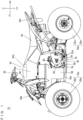
Fig. 1 is a side view which shows a vehicle according to a preferred embodiment. -
Fig. 2 is a plan view which shows the vehicle inFig. 1 . -
Fig. 3 is a perspective view which shows the vehicle with exterior components removed. -
Fig. 4 is a front view which shows the vehicle inFig. 3 . -
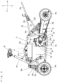
Fig. 5 is a side view which shows the vehicle inFig. 3 viewed from the left. -
Fig. 6 is a side view which shows the vehicle inFig. 3 viewed from the right. -
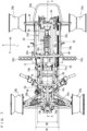
Fig. 7 is a plan view which shows the vehicle inFig. 3 . -
Fig. 8 is a bottom view which shows the vehicle inFig. 3 . -
Fig. 9 is an illustrative sectional view taken along line A-A inFig 7 . -
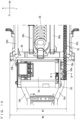
Fig. 10 is an enlarged plan view which shows a top portion and surroundings thereof of a drive motor. -
Fig. 11 is a sectional view taken along line B-B inFig. 10 . -
Figs. 12A and 12B are diagrammatic representations which show a vehicle according to another preferred embodiment, whereinFig. 12A is a front view andFig. 12B is a plan view. -
Figs. 13A and 13B are diagrammatic representations which show a vehicle according to still another preferred embodiment, whereinFig. 13A is a front view andFig. 13B is a plan view. -
Figs. 14A and 14B are diagrammatic representations which show a vehicle according to still another preferred embodiment, whereinFig. 14A is a front view andFig. 14B is a plan view. - Hereinafter, preferred embodiments will be described with reference to the drawings. It should be noted here that the terms front and rear, left and right, and up and down used in the preferred embodiments refer to front and rear, left and right, and up and down based on the state where a driver of the
vehicle 10 is seated in a straddled seat 82 (which will be described below), facing a bar handle 50 (which will be described below). In the drawings, "Fr" indicates forward, "Rr" indicates rearward, "R" indicates rightward, "L" indicates leftward, "U" indicates upward, and "Lo" indicates downward. Accordingly, a fore-aft direction of the vehicle extends from rearward Rr to forward Fr and vice versa. A left-right direction of the vehicle extends from the rightward R to leftward L and vice versa. The left-right direction of the vehicle is synonymous to the widthwise direction of the vehicle. An upward-downward direction of the vehicle extends from upward U to downward and vice versa. The upward-downward direction of the vehicle is synonymous to the vertical direction of the vehicle. - Referring to
Fig. 1 andFig. 2 , avehicle 10 according to a preferred embodiment is an electric ATV which carries one person. - Referring to
Fig. 3 through Fig. 9 , thevehicle 10 includes abody frame 12. Thebody frame 12 includes a pair ofupper frames lower frames front frame 18, and arear frame 20. - The pair of
upper frames upper frames support frame 14c which supports a steering shaft 48 (which will be described below). Thesupport frame 14c is generally V-shaped, and is provided on the pair ofupper frames - The pair of
lower frames upper frames - The
front frame 18 connects front portions of the pair ofupper frames lower frames front frame 18 includes a pair offirst frames upper frames lower frames second frames upper frames lower frames second frames - The
rear frame 20 connects rear portions of the pair ofupper frames lower frames rear frame 20 includes athird frame 20a which is generally U-shaped in a rear view and generally V-shaped in a side view and connects the rear portions of the pair ofupper frames lower frames cross member 20b which connects two end portions of thethird frame 20a; a pair offourth frames third frame 20a; a pair offifth frames third frame 20a; and asixth frame 20g which is generally U-shaped. Thesixth frame 20g is located so that its first end portion is sandwiched by a rear end portion of thefourth frame 20c and a rear end portion of thefifth frame 20e while its second end portion is sandwiched by a rear end portion of thefourth frame 20d and a rear end portion of thefifth frame 20f. - A pair of
front wheels body frame 12 and a pair ofrear wheels Fig. 1 andFig. 2 ). Thefront wheels wheels tires wheels rear wheels wheels tires wheels - The pair of
front wheels body frame 12 viasuspensions - The pair of
rear wheels body frame 12 via asuspension 36,swing arms third frame 20a of therear frame 20 are connected with each other via apivot shaft 40 which extends widthwise of the vehicle. Therear wheels axle 42 which extends widthwise of the vehicle. At an intermediate portion of theaxle 42, anarm support portion 44 is attached rotatably with respect to theaxle 42. Thepivot shaft 40 and thearm support portion 44 are connected with each other by theswing arms swing arms pivot shaft 40 and support the pair ofrear wheels arm support portion 44. Theswing arms portion 46. Thesuspension 36 is provided at an intermediate portion in the vehicle's widthwise direction, and connects thethird frame 20a with the connectingportion 46. - A steering
shaft 48 is provided to extend through a space between the pair ofupper frames shaft 48 has its lower end portion connected with the pair offirst frames front frame 18. The steeringshaft 48 is supported, at a position slightly higher than its intermediate portion, by thesupport frame 14c. A bar handle 50 to steer the pair offront wheels shaft 48. The bar handle 50 is provided at a higher position than the straddledseat 82. When the bar handle 50 is operated, the steeringshaft 48 is rotated to steer thefront wheels - A pair of
steps third frame 20a of therear frame 20 to extend outward of the vehicle. - The
body frame 12 supports adrive motor 54 which drives the pair ofrear wheels battery 56 which supplies electric power to thedrive motor 54. Thedrive motor 54 and thebattery 56 are provided on the pair oflower frames drive motor 54 is behind thebattery 56, at a location farther forward than theswing arms drive motor 54 is forward of therear frame 20. Preferably, thebattery 56 is an interchangeable rechargeable battery. - The
drive motor 54 includes anoutput shaft 54a. In order to fix thedrive motor 54 to thelower frame 16a, amotor fixing bracket 58 is provided between an output side of thedrive motor 54 and thelower frame 16a. - Referring also to
Fig. 10 andFig. 11 , themotor fixing bracket 58 is attached to an output-side end portion (left end portion in the present preferred embodiment) of thedrive motor 54 with a plurality (four in the present preferred embodiment) offasteners 60. Themotor fixing bracket 58 has its lower end portion connected with aflange portion 62 provided in thelower frame 16a with a plurality (two in the present preferred embodiment) offasteners 64. Themotor fixing bracket 58 includes a through-hole 58a, and theoutput shaft 54a of thedrive motor 54 has its tip portion exposed from the through-hole 58a. Theoutput shaft 54a is rotatable with respect to themotor fixing bracket 58 via abearing 66. - Referring to
Fig. 6 , amotor fixing bracket 68 is attached to a non-output-side end portion (right end portion in the present preferred embodiment), where theoutput shaft 54a is not provided, of thedrive motor 54, with a plurality (two in the present preferred embodiment) offasteners 70. Themotor fixing bracket 68 is attached to thelower frame 16b with a plurality (two in the present preferred embodiment) offasteners 72. - As described, the
drive motor 54 is fixed to the pair oflower frames motor fixing brackets - Referring to
Fig. 5 ,Fig. 6 andFig. 9 , in a side view, thedrive motor 54 and thebattery 56 are located in a region which is surrounded by theupper frames lower frames second frames front frame 18, and thethird frame 20a of therear frame 20. The open space defined by theupper frames lower frames front frame 18, and therear frame 20 has a shape and a size for each of thedrive motor 54 and thebattery 56 to be installed therein from a side. In the present preferred embodiment, thedrive motor 54 and thebattery 56 are located inside the region which is surrounded by theupper frames lower frames second frames front frame 18, and thethird frame 20a of therear frame 20, and do not overlap these frames in a side view. In a side view, thedrive motor 54 and thebattery 56 do not protrude downward from the pair oflower frames - Referring to
Fig. 7 andFig. 8 , thebattery 56 is provided at a center location in the vehicle's width direction. Thebattery 56 overlaps the pair oflower frames Fig. 10 , thedrive motor 54 is slightly offset with respect to the vehicle's center (offset rightward in the present preferred embodiment) in the width direction. Thedrive motor 54 and thebattery 56 have their respective widthwise lengths W1, W2 shorter than a widthwise dimension W3 of therear frame 20 in a plan view. Thedrive motor 54 and thebattery 56 are farther inward (inboard) in the vehicle width direction than therear frame 20, and farther inward (inboard) in the vehicle width direction than thethird frame 20a. The arrangement makes it easy for the driver of the vehicle to hold the vehicle body between his/her knees. In a plan view, thedrive motor 54 and thebattery 56 have their respective widthwise lengths W1, W2 shorter than an end-to-end length L of thepivot shaft 40. In a plan view, thedrive motor 54 and thebattery 56 have their respective widthwise lengths W1, W2 shorter than a distance D between thesteps steps drive motor 54 and thebattery 56 do not interfere with the driver, thus making it possible to enjoy a comfortable ride. - Referring to
Fig. 5 through Fig. 7 , a motor control unit (MCU) 74 is provided above thebattery 56 in order to control thedrive motor 54. Themotor control unit 74 is supported by the pair ofupper frames - The
drive motor 54 and the pair ofrear wheels power transmission member 76. Power from theoutput shaft 54a is transmitted to the pair ofrear wheels power transmission member 76 to drive the pair ofrear wheels power transmission member 76 includes asprocket 76a attached to theoutput shaft 54a, a sprocket (not illustrated) attached to theaxle 42, and achain 76b connecting thesprocket 76a and the axle-side sprocket with each other. Therefore, the power from theoutput shaft 54a is transmitted through thesprocket 76a, thechain 76b, and the axle-side sprocket, to theaxle 42, and then to the pair ofrear wheels power transmission member 76, which includes thesprocket 76a, thechain 76b and the axle-side sprocket, is located farther inward in the vehicle width direction than therear frame 20, and farther inward in the vehicle width direction than thethird frame 20a. In order to cover thesprocket 76a of thepower transmission member 76 and a portion of thechain 76b, a powertransmission member cover 78 is attached to the motor fixing bracket 58 (seeFig. 1 ). The powertransmission member cover 78 is attached to themotor fixing bracket 58 with a plurality (three in the present preferred embodiment) offasteners 80. - Referring to
Fig. 1 andFig. 2 , the straddledseat 82 and anexterior portion 84 are mounted to thebody frame 12. - The straddled
seat 82 is at a position higher than thedrive motor 54, and is supported by the pair offourth frames rear frame 20. - The
exterior portion 84 includes atop cover 84a located forward of the straddledseat 82, afront fender 84b located forward of thetop cover 84a, and arear fender 84c located behind thetop cover 84a to surround the straddledseat 82. Thetop cover 84a includes aconsole box 84d attached thereto. Theconsole box 84d is above thebattery 56. - According to the
vehicle 10 as described, thedrive motor 54 and the pair ofrear wheels power transmission member 76, and thedrive motor 54 is located farther forward than theswing arms power transmission member 76, the layout of thedrive motor 54 is not limited by theswing arms drive motor 54. Also, the layout of thesprocket 76a is easy, thus making it easy to secure a chain line. - The
power transmission member 76 is provided farther inward in the vehicle width direction than therear frame 20. Therefore, it is possible to make effective use of a space which is outboard of therear frame 20. - The widthwise length W1 of the
drive motor 54 is shorter than the end-to-end length L of thepivot shaft 40. Therefore, it is possible to reduce the dimension of thedrive motor 54 in the widthwise direction of the vehicle, thus making it possible to utilize the space on the side of thedrive motor 54 effectively. - It is possible to fix the
drive motor 54 to thelower frame 16a easily via themotor fixing bracket 58. - By attaching the power
transmission member cover 78 directly to themotor fixing bracket 58, it is possible to decrease the number of parts. - Both sides of the
drive motor 54 is fixed to the pair oflower frames drive motor 54, thus making it possible to reduce wobble of thedrive motor 54. Therefore, it becomes possible to further stabilize operation of thedrive motor 54. - The
drive motor 54 is located in a region surrounded by theupper frames lower frames front frame 18, and therear frame 20 in a side view. Therefore, thedrive motor 54 is attachable/detachable from a side of the vehicle, i.e., thus making assembly and maintenance operations easy. - In a side view, the
drive motor 54 is forward of therear frame 20. Therefore, it is now possible to locate heavy components at/around the vehicle's center of gravity, and concentrate the mass of thevehicle 10. Also, it is possible to improve the freedom of the size of thedrive motor 54 without limitation posed by theswing arms - By offsetting the
drive motor 54 with respect to the vehicle center, toward the opposite side from thesprocket 76a (rightward in the present preferred embodiment), it becomes possible to increase a layout space on the side of thesprocket 76a without increasing the width of thebody frame 12. - Preferred embodiments described above are suitably applied to an ATV.
- It should be noted here that as will be described below, there may be a transmission provided between the drive motor and the power transmission member. In
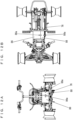
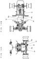
Fig. 12A through Fig. 14B , a drive motor and a transmission are shown schematically as white rectangles to help understanding of the these structures. Note, however, that the drive motor and the transmission are located in a region surrounded by upper frames, lower frames, a front frame, and a rear frame in a side view. Also, it is preferable that the battery is located at a vacant space within the region in the side view. - In a preferred embodiment shown in
Figs. 12A and 12B , atransmission 88 is provided between adrive motor 86 and thepower transmission member 76 in order to change the speed of an output from thedrive motor 86. Thedrive motor 86 is offset rightward with respect to the vehicle's center. Thedrive motor 86 includes anoutput shaft 86a, which is located leftward of thedrive motor 86 and connected with thetransmission 88. Thetransmission 88 is on a left side of thedrive motor 86. Thetransmission 88 includes anoutput shaft 88a, with which thepower transmission member 76 is connected. - According to the present preferred embodiment, it is possible to utilize the
drive motor 86 highly efficiently, and improve electricity consumption and travel distance. Also, theoutput shaft 88a of thetransmission 88 is able to simply be connected directly with thepower transmission member 76. Therefore, the arrangement makes it possible to improve the freedom of layout of thedrive motor 86. The same advantages are also provided in preferred embodiments shown inFigs. 13A and 13B andFigs. 14A and 14B . - Also, the arrangement allows the
drive motor 86 and thetransmission 88 to be more compact, and to improve the freedom of layout of the battery and so on. Further, the addition of thetransmission 88 does not affect the size of the vehicle, i.e., it is possible to prevent an increase in the total length of the vehicle, and therefore possible to concentrate the mass of the vehicle. - In a preferred embodiment shown in
Figs. 13A and 13B , atransmission 92 is provided between adrive motor 90 and thepower transmission member 76 in order to change the speed of an output from thedrive motor 90. Thedrive motor 90 is offset leftward with respect to the vehicle's center. Thedrive motor 90 includes anoutput shaft 90a, which is located rightward of thedrive motor 90. Thetransmission 92 is positioned at a rightward-and-rearward location of thedrive motor 90. Thetransmission 92 includes anoutput shaft 92a with which thepower transmission member 76 is connected. - According to the present preferred embodiment, it is possible to improve the freedom of layout of the
drive motor 90 with respect to the drive sprocket (the sprocket attached to theoutput shaft 92a) the location of which is limited. Also, it is possible to prevent an increase in the vehicle widthwise dimension. Further, it is possible to increase the freedom of the speed changing ratio. - In a preferred embodiment shown in
Figs. 14A and 14B , atransmission 96 is provided between adrive motor 94 and thepower transmission member 76 in order to change a speed of an output from thedrive motor 94. Thedrive motor 94 is offset rightward with respect to the vehicle's center. Thedrive motor 94 includes anoutput shaft 94a, which is located leftward of thedrive motor 94 and connected with thetransmission 96. Thetransmission 96 is positioned on a left side of but slightly rearward than thedrive motor 94. Thetransmission 96 includes anoutput shaft 96a with which thepower transmission member 76 is connected. - According to the present preferred embodiment, it is possible to improve the freedom of layout of the
drive motor 94 with respect to the drive sprocket (the sprocket attached to theoutput shaft 96a) the location of which is limited. Also, it is possible to keep the vehicle widthwise dimension compact. Further, it is possible to increase the freedom of the speed changing ratio. - In preferred embodiments described above, description was made for a case where the
vehicle 10 includes a plurality ofswing arms
Claims (11)
- A vehicle (10) comprising:a pair of upper frames (14a, 14b) spaced apart in a left-right direction of the vehicle;a pair of lower frames (16a, 16b) spaced apart in the left-right direction of the vehicle;a front frame (18) connecting front portions of the pair of upper frames (14a, 14b) with the pair of lower frames (16a, 16b);a rear frame (20) connecting rear portions of the pair of upper frames (14a, 14b) with rear portions of the pair of lower frames (16a, 16b);a pair of rear wheels (24a, 24b);a drive motor (54, 86, 90, 94) to drive the pair of rear wheels (24a, 24b);a battery (56) configured to supply electric power to the drive motor (54, 86, 90, 94);an endless power transmission member (76) configured to connect the drive motor (54, 86, 90, 94) with the pair of rear wheels (24a, 24b);a pivot shaft (40) attached to the rear frame (20) and extending in a widthwise direction of the vehicle; andat least one swing arm (38a, 38b) supported pivotably by the pivot shaft (40) and supporting the pair of rear wheels (24a, 24b); whereinthe drive motor (54, 86, 90, 94) is located farther forward than the swing arm (38a, 38b) with regard to a fore-aft direction of the vehicle.
- The vehicle (10) according to claim 1, wherein the power transmission member (76) is located inward of the rear frame (20) in the width direction of the vehicle.
- The vehicle (10) according to claim 1 or 2, wherein a widthwise length (W1) of the drive motor (54, 86, 90, 94) in the widthwise direction of the vehicle is shorter than an end-to-end length (L) of the pivot shaft (40).
- The vehicle (10) according to any one of the claims 1 to 3, further comprising a motor fixing bracket (58, 68) between an output side of the drive motor (54, 86, 90, 94) and the lower frame (16a, 16b) to fix the drive motor (54, 86, 90, 94) to the lower frame (16a, 16b).
- The vehicle (10) according to claim 4, further comprising a power transmission member cover (78) attached to the motor fixing bracket (58, 68) to cover the power transmission member (76).
- The vehicle (10) according to any one of the claims 1 to 5, wherein both sides of the drive motor (54, 86, 90, 94) are fixed to the pair of lower frames (16a, 16b).
- The vehicle (10) according to any one of the claims 1 to 6, wherein the drive motor (54, 86, 90, 94) is located in a region surrounded by the upper frames (14a, 14b), the lower frames (16a, 16b), the front frame (18), and the rear frame (20) in a side view of the vehicle.
- The vehicle (10) according to any one of the claims 1 to 7, wherein the drive motor (54, 86, 90, 94) is farther forward than the rear frame (20) with regard to the fore-aft direction of the vehicle in a side view of the vehicle.
- The vehicle (10) according to any one of the claims 1 to 8, further comprising a transmission between the drive motor (54, 86, 90, 94) and the power transmission member (76) to change a speed of an output from the drive motor (54, 86, 90, 94).
- The vehicle (10) according to any one of the claims 1 to 9, further comprising:a straddled seat (82) provided at a higher position than the drive motor (54, 86, 90, 94) with regard to an upward-downward direction of the vehicle; anda bar handle (50) provided at a higher position than the straddled seat (82) with regard to an upward-downward direction of the vehicle.
- The vehicle (10) according to any one of the claims 1 to 10, further comprising:
a body frame (12) having a pair of swing arms (38a, 38b) supported pivotably by the pivot shaft (40) and supporting the pair of rear wheels (24a, 24b).
Applications Claiming Priority (1)
| Application Number | Priority Date | Filing Date | Title |
|---|---|---|---|
| JP2021207433A JP2023092285A (en) | 2021-12-21 | 2021-12-21 | vehicle |
Publications (2)
| Publication Number | Publication Date |
|---|---|
| EP4201720A1 true EP4201720A1 (en) | 2023-06-28 |
| EP4201720B1 EP4201720B1 (en) | 2026-03-04 |
Family
ID=84535727
Family Applications (1)
| Application Number | Title | Priority Date | Filing Date |
|---|---|---|---|
| EP22213425.6A Active EP4201720B1 (en) | 2021-12-21 | 2022-12-14 | Vehicle |
Country Status (3)
| Country | Link |
|---|---|
| US (1) | US20230192232A1 (en) |
| EP (1) | EP4201720B1 (en) |
| JP (1) | JP2023092285A (en) |
Families Citing this family (1)
| Publication number | Priority date | Publication date | Assignee | Title |
|---|---|---|---|---|
| CA3206376A1 (en) * | 2021-01-29 | 2022-08-04 | Polaris Industries Inc. | Youth electric vehicle |
Citations (5)
| Publication number | Priority date | Publication date | Assignee | Title |
|---|---|---|---|---|
| JP4214759B2 (en) | 2002-10-29 | 2009-01-28 | スズキ株式会社 | Electric rough terrain vehicle |
| JP5509811B2 (en) | 2009-11-25 | 2014-06-04 | スズキ株式会社 | Electric rough terrain vehicle |
| EP2799320A1 (en) * | 2011-12-28 | 2014-11-05 | Kawasaki Jukogyo Kabushiki Kaisha | Electric straddled vehicle |
| US20150251716A1 (en) * | 2012-10-03 | 2015-09-10 | Kawasaki Jukogyo Kabushiki Kaisha | Assembling Method and Assembling Management Method of Electric Vehicle |
| US20200031425A1 (en) * | 2018-07-30 | 2020-01-30 | Harley-Davidson Motor Company Group, LLC | Assembly structure and method for electric vehicle |
Family Cites Families (29)
| Publication number | Priority date | Publication date | Assignee | Title |
|---|---|---|---|---|
| US3533484A (en) * | 1968-05-16 | 1970-10-13 | Garfield A Wood Jr | Electric power unit |
| US3554311A (en) * | 1968-08-02 | 1971-01-12 | Revolt Inc | Electrical vehicle |
| EP0469995B1 (en) * | 1990-08-02 | 1995-10-04 | Honda Giken Kogyo Kabushiki Kaisha | Electrically operated vehicle |
| US6799781B2 (en) * | 2000-03-13 | 2004-10-05 | Bombardier Recreational Products Inc. | Frames for all-terrain vehicles |
| JP2003011874A (en) * | 2001-06-29 | 2003-01-15 | Suzuki Motor Corp | Body frame of saddle riding type rough terrain vehicle and method of manufacturing the same |
| JP4144219B2 (en) * | 2001-12-26 | 2008-09-03 | スズキ株式会社 | Rear wheel suspension system for saddle riding type vehicles |
| JP2004314939A (en) * | 2003-04-04 | 2004-11-11 | Honda Motor Co Ltd | Frame structure of saddle-ride type vehicle and frame manufacturing method |
| DE602004024325D1 (en) * | 2003-09-29 | 2010-01-07 | Nissan Motor | DRIVE MOTOR MOUNTING CONSTRUCTION AND FASTENING METHOD |
| CA2496491C (en) * | 2004-02-13 | 2009-07-21 | Honda Motor Co., Ltd. | Vehicle body frame structure for all-terrain vehicle |
| WO2006110687A2 (en) * | 2005-04-11 | 2006-10-19 | Bombardier Recreational Products Inc. | All-terrain vehicle |
| JP4899625B2 (en) * | 2006-05-12 | 2012-03-21 | スズキ株式会社 | Saddle-type rough terrain vehicle |
| JP2011143857A (en) * | 2010-01-15 | 2011-07-28 | Honda Motor Co Ltd | Vehicle |
| AT12217U1 (en) * | 2010-08-31 | 2012-01-15 | Daniel Preining | ADAPTER FOR CONNECTING AN ELECTRIC DRIVE UNIT TO VEHICLE FRAME |
| WO2012090246A1 (en) * | 2010-12-27 | 2012-07-05 | 川崎重工業株式会社 | Saddle-type electric vehicle and structure for mounting power controller in said electric vehicle |
| US9278725B2 (en) * | 2011-12-28 | 2016-03-08 | Kawasaki Jukogyo Kabushiki Kaisha | Straddle electric vehicle |
| CN103946108B (en) * | 2011-12-28 | 2016-08-24 | 川崎重工业株式会社 | Saddle-type electric vehicle |
| JP5960844B2 (en) * | 2012-12-25 | 2016-08-02 | 川崎重工業株式会社 | Electric vehicle |
| US9579983B2 (en) * | 2012-12-25 | 2017-02-28 | Kawasaki Jukogyo Kabushiki Kaisha | Electric vehicle |
| JP2016203953A (en) * | 2015-04-28 | 2016-12-08 | ヤマハ発動機株式会社 | Electric vehicle |
| JP2018090209A (en) * | 2016-12-07 | 2018-06-14 | ヤマハ発動機株式会社 | Saddle-riding type electric vehicle and electrically-driven power unit |
| DE102017001557A1 (en) * | 2017-02-20 | 2018-08-23 | Werner Krammel | Vehicle with differential |
| US10822037B2 (en) * | 2017-11-15 | 2020-11-03 | Zhejiang CFMOTO Power Co., Ltd. | Frame structure for off road vehicle |
| JP2019218009A (en) * | 2018-06-22 | 2019-12-26 | ヤマハ発動機株式会社 | vehicle |
| JP6749979B2 (en) * | 2018-09-27 | 2020-09-02 | 本田技研工業株式会社 | Saddle-type electric vehicle |
| US20240343108A1 (en) * | 2019-10-30 | 2024-10-17 | Louis Decuzzi | Drive System for All-Terrain Vehicle (ATV) |
| US11491857B2 (en) * | 2019-12-13 | 2022-11-08 | Stephen P. Hendricks | Method and apparatus for conversion of motorized vehicles to electric vehicles |
| CA3206376A1 (en) * | 2021-01-29 | 2022-08-04 | Polaris Industries Inc. | Youth electric vehicle |
| CN214776329U (en) * | 2021-06-11 | 2021-11-19 | 格力博(江苏)股份有限公司 | An electric all-terrain vehicle |
| US20230226928A1 (en) * | 2021-09-17 | 2023-07-20 | Polaris Industries Inc. | Electric all-terrain vehicle |
-
2021
- 2021-12-21 JP JP2021207433A patent/JP2023092285A/en active Pending
-
2022
- 2022-12-14 EP EP22213425.6A patent/EP4201720B1/en active Active
- 2022-12-15 US US18/081,749 patent/US20230192232A1/en active Pending
Patent Citations (5)
| Publication number | Priority date | Publication date | Assignee | Title |
|---|---|---|---|---|
| JP4214759B2 (en) | 2002-10-29 | 2009-01-28 | スズキ株式会社 | Electric rough terrain vehicle |
| JP5509811B2 (en) | 2009-11-25 | 2014-06-04 | スズキ株式会社 | Electric rough terrain vehicle |
| EP2799320A1 (en) * | 2011-12-28 | 2014-11-05 | Kawasaki Jukogyo Kabushiki Kaisha | Electric straddled vehicle |
| US20150251716A1 (en) * | 2012-10-03 | 2015-09-10 | Kawasaki Jukogyo Kabushiki Kaisha | Assembling Method and Assembling Management Method of Electric Vehicle |
| US20200031425A1 (en) * | 2018-07-30 | 2020-01-30 | Harley-Davidson Motor Company Group, LLC | Assembly structure and method for electric vehicle |
Also Published As
| Publication number | Publication date |
|---|---|
| US20230192232A1 (en) | 2023-06-22 |
| EP4201720B1 (en) | 2026-03-04 |
| JP2023092285A (en) | 2023-07-03 |
Similar Documents
| Publication | Publication Date | Title |
|---|---|---|
| US4798400A (en) | Light-weight and strong vehicle frame for a four wheeled buggy operated by a seated driver | |
| JP4619819B2 (en) | Power steering system for rough terrain vehicle | |
| US20040035626A1 (en) | Vehicle and adjustable steering shaft therefor | |
| US20040129483A1 (en) | Vehicle and adjustable steering shaft therefor | |
| US8256555B2 (en) | Three-wheeled motorcycle | |
| CN111867927B (en) | straddle-type electric vehicle | |
| US20160129783A1 (en) | Work vehicle | |
| EP4201720B1 (en) | Vehicle | |
| CN111886177B (en) | Saddle-ride type electric vehicle | |
| CN1329218C (en) | Motor driven rough-road driving four-wheeled vehicle | |
| EP4206013B1 (en) | Vehicle | |
| US20080001377A1 (en) | Axle Assembly | |
| US20250206410A1 (en) | Saddle riding type electric vehicle | |
| EP4197890A1 (en) | Traveling vehicle | |
| US20230192215A1 (en) | Vehicle | |
| JP2024101025A5 (en) | ||
| JP2025037444A (en) | Electric crawler vehicle | |
| WO2019186943A1 (en) | Saddle riding-type electric vehicle | |
| US20220135132A1 (en) | Vehicle | |
| JPH1159488A (en) | Riding electric vehicle | |
| EP4667337A1 (en) | Lean vehicle | |
| JP2024034182A (en) | electric work vehicle | |
| JP2025157782A (en) | Work vehicle | |
| JP2003040149A (en) | Passenger management machine | |
| JP2025157783A (en) | Work vehicle |
Legal Events
| Date | Code | Title | Description |
|---|---|---|---|
| PUAI | Public reference made under article 153(3) epc to a published international application that has entered the european phase |
Free format text: ORIGINAL CODE: 0009012 |
|
| STAA | Information on the status of an ep patent application or granted ep patent |
Free format text: STATUS: REQUEST FOR EXAMINATION WAS MADE |
|
| 17P | Request for examination filed |
Effective date: 20221214 |
|
| AK | Designated contracting states |
Kind code of ref document: A1 Designated state(s): AL AT BE BG CH CY CZ DE DK EE ES FI FR GB GR HR HU IE IS IT LI LT LU LV MC ME MK MT NL NO PL PT RO RS SE SI SK SM TR |
|
| P01 | Opt-out of the competence of the unified patent court (upc) registered |
Effective date: 20230713 |
|
| RBV | Designated contracting states (corrected) |
Designated state(s): AL AT BE BG CH CY CZ DE DK EE ES FI FR GB GR HR HU IE IS IT LI LT LU LV MC ME MK MT NL NO PL PT RO RS SE SI SK SM TR |
|
| STAA | Information on the status of an ep patent application or granted ep patent |
Free format text: STATUS: EXAMINATION IS IN PROGRESS |
|
| 17Q | First examination report despatched |
Effective date: 20240205 |
|
| RIC1 | Information provided on ipc code assigned before grant |
Ipc: B60K 1/00 20060101AFI20251002BHEP Ipc: B60K 17/04 20060101ALI20251002BHEP Ipc: B60K 1/04 20190101ALN20251002BHEP |
|
| GRAP | Despatch of communication of intention to grant a patent |
Free format text: ORIGINAL CODE: EPIDOSNIGR1 |
|
| STAA | Information on the status of an ep patent application or granted ep patent |
Free format text: STATUS: GRANT OF PATENT IS INTENDED |
|
| RIC1 | Information provided on ipc code assigned before grant |
Ipc: B60K 1/00 20060101AFI20251021BHEP Ipc: B60K 17/04 20060101ALI20251021BHEP Ipc: B60K 1/04 20190101ALN20251021BHEP |
|
| INTG | Intention to grant announced |
Effective date: 20251113 |
|
| GRAS | Grant fee paid |
Free format text: ORIGINAL CODE: EPIDOSNIGR3 |
|
| GRAA | (expected) grant |
Free format text: ORIGINAL CODE: 0009210 |
|
| STAA | Information on the status of an ep patent application or granted ep patent |
Free format text: STATUS: THE PATENT HAS BEEN GRANTED |
|
| AK | Designated contracting states |
Kind code of ref document: B1 Designated state(s): AL AT BE BG CH CY CZ DE DK EE ES FI FR GB GR HR HU IE IS IT LI LT LU LV MC ME MK MT NL NO PL PT RO RS SE SI SK SM TR |
|
| REG | Reference to a national code |
Ref country code: CH Ref legal event code: F10 Free format text: ST27 STATUS EVENT CODE: U-0-0-F10-F00 (AS PROVIDED BY THE NATIONAL OFFICE) Effective date: 20260304 Ref country code: GB Ref legal event code: FG4D |
|
| REG | Reference to a national code |
Ref country code: DE Ref legal event code: R096 Ref document number: 602022031544 Country of ref document: DE |
|
| REG | Reference to a national code |
Ref country code: IE Ref legal event code: FG4D |
|
| PG25 | Lapsed in a contracting state [announced via postgrant information from national office to epo] |
Ref country code: RS Free format text: LAPSE BECAUSE OF FAILURE TO SUBMIT A TRANSLATION OF THE DESCRIPTION OR TO PAY THE FEE WITHIN THE PRESCRIBED TIME-LIMIT Effective date: 20260604 |
|
| PG25 | Lapsed in a contracting state [announced via postgrant information from national office to epo] |
Ref country code: ES Free format text: LAPSE BECAUSE OF FAILURE TO SUBMIT A TRANSLATION OF THE DESCRIPTION OR TO PAY THE FEE WITHIN THE PRESCRIBED TIME-LIMIT Effective date: 20260304 |
|
| REG | Reference to a national code |
Ref country code: NL Ref legal event code: MP Effective date: 20260304 |
|
| PG25 | Lapsed in a contracting state [announced via postgrant information from national office to epo] |
Ref country code: PL Free format text: LAPSE BECAUSE OF FAILURE TO SUBMIT A TRANSLATION OF THE DESCRIPTION OR TO PAY THE FEE WITHIN THE PRESCRIBED TIME-LIMIT Effective date: 20260304 |
|
| PG25 | Lapsed in a contracting state [announced via postgrant information from national office to epo] |
Ref country code: GR Free format text: LAPSE BECAUSE OF FAILURE TO SUBMIT A TRANSLATION OF THE DESCRIPTION OR TO PAY THE FEE WITHIN THE PRESCRIBED TIME-LIMIT Effective date: 20260605 |
|
| REG | Reference to a national code |
Ref country code: LT Ref legal event code: MG9D |
|
| PG25 | Lapsed in a contracting state [announced via postgrant information from national office to epo] |
Ref country code: LT Free format text: LAPSE BECAUSE OF FAILURE TO SUBMIT A TRANSLATION OF THE DESCRIPTION OR TO PAY THE FEE WITHIN THE PRESCRIBED TIME-LIMIT Effective date: 20260304 |
|
| PG25 | Lapsed in a contracting state [announced via postgrant information from national office to epo] |
Ref country code: NO Free format text: LAPSE BECAUSE OF FAILURE TO SUBMIT A TRANSLATION OF THE DESCRIPTION OR TO PAY THE FEE WITHIN THE PRESCRIBED TIME-LIMIT Effective date: 20260604 |
|
| PG25 | Lapsed in a contracting state [announced via postgrant information from national office to epo] |
Ref country code: SE Free format text: LAPSE BECAUSE OF FAILURE TO SUBMIT A TRANSLATION OF THE DESCRIPTION OR TO PAY THE FEE WITHIN THE PRESCRIBED TIME-LIMIT Effective date: 20260304 Ref country code: FI Free format text: LAPSE BECAUSE OF FAILURE TO SUBMIT A TRANSLATION OF THE DESCRIPTION OR TO PAY THE FEE WITHIN THE PRESCRIBED TIME-LIMIT Effective date: 20260304 |
|
| PG25 | Lapsed in a contracting state [announced via postgrant information from national office to epo] |
Ref country code: HR Free format text: LAPSE BECAUSE OF FAILURE TO SUBMIT A TRANSLATION OF THE DESCRIPTION OR TO PAY THE FEE WITHIN THE PRESCRIBED TIME-LIMIT Effective date: 20260304 |
|
| PG25 | Lapsed in a contracting state [announced via postgrant information from national office to epo] |
Ref country code: LV Free format text: LAPSE BECAUSE OF FAILURE TO SUBMIT A TRANSLATION OF THE DESCRIPTION OR TO PAY THE FEE WITHIN THE PRESCRIBED TIME-LIMIT Effective date: 20260304 |
|
| PG25 | Lapsed in a contracting state [announced via postgrant information from national office to epo] |
Ref country code: BG Free format text: LAPSE BECAUSE OF FAILURE TO SUBMIT A TRANSLATION OF THE DESCRIPTION OR TO PAY THE FEE WITHIN THE PRESCRIBED TIME-LIMIT Effective date: 20260304 |