EP4201710A1 - Tire - Google Patents
Tire Download PDFInfo
- Publication number
- EP4201710A1 EP4201710A1 EP22211588.3A EP22211588A EP4201710A1 EP 4201710 A1 EP4201710 A1 EP 4201710A1 EP 22211588 A EP22211588 A EP 22211588A EP 4201710 A1 EP4201710 A1 EP 4201710A1
- Authority
- EP
- European Patent Office
- Prior art keywords
- tire
- depth
- sipe
- piece
- straight
- Prior art date
- Legal status (The legal status is an assumption and is not a legal conclusion. Google has not performed a legal analysis and makes no representation as to the accuracy of the status listed.)
- Pending
Links
- 230000000694 effects Effects 0.000 description 9
- 230000000669 biting effect Effects 0.000 description 3
- 238000010008 shearing Methods 0.000 description 3
- 238000010521 absorption reaction Methods 0.000 description 1
- 230000003247 decreasing effect Effects 0.000 description 1
- 238000012986 modification Methods 0.000 description 1
- 230000004048 modification Effects 0.000 description 1
- XLYOFNOQVPJJNP-UHFFFAOYSA-N water Substances O XLYOFNOQVPJJNP-UHFFFAOYSA-N 0.000 description 1
Images


Classifications
-
- B—PERFORMING OPERATIONS; TRANSPORTING
- B60—VEHICLES IN GENERAL
- B60C—VEHICLE TYRES; TYRE INFLATION; TYRE CHANGING; CONNECTING VALVES TO INFLATABLE ELASTIC BODIES IN GENERAL; DEVICES OR ARRANGEMENTS RELATED TO TYRES
- B60C11/00—Tyre tread bands; Tread patterns; Anti-skid inserts
- B60C11/03—Tread patterns
- B60C11/12—Tread patterns characterised by the use of narrow slits or incisions, e.g. sipes
- B60C11/1236—Tread patterns characterised by the use of narrow slits or incisions, e.g. sipes with special arrangements in the tread pattern
-
- B—PERFORMING OPERATIONS; TRANSPORTING
- B60—VEHICLES IN GENERAL
- B60C—VEHICLE TYRES; TYRE INFLATION; TYRE CHANGING; CONNECTING VALVES TO INFLATABLE ELASTIC BODIES IN GENERAL; DEVICES OR ARRANGEMENTS RELATED TO TYRES
- B60C11/00—Tyre tread bands; Tread patterns; Anti-skid inserts
- B60C11/03—Tread patterns
- B60C11/12—Tread patterns characterised by the use of narrow slits or incisions, e.g. sipes
- B60C11/1204—Tread patterns characterised by the use of narrow slits or incisions, e.g. sipes with special shape of the sipe
- B60C11/1218—Three-dimensional shape with regard to depth and extending direction
-
- B—PERFORMING OPERATIONS; TRANSPORTING
- B60—VEHICLES IN GENERAL
- B60C—VEHICLE TYRES; TYRE INFLATION; TYRE CHANGING; CONNECTING VALVES TO INFLATABLE ELASTIC BODIES IN GENERAL; DEVICES OR ARRANGEMENTS RELATED TO TYRES
- B60C11/00—Tyre tread bands; Tread patterns; Anti-skid inserts
- B60C11/03—Tread patterns
- B60C11/12—Tread patterns characterised by the use of narrow slits or incisions, e.g. sipes
- B60C11/1259—Depth of the sipe
- B60C11/1263—Depth of the sipe different within the same sipe
-
- B—PERFORMING OPERATIONS; TRANSPORTING
- B60—VEHICLES IN GENERAL
- B60C—VEHICLE TYRES; TYRE INFLATION; TYRE CHANGING; CONNECTING VALVES TO INFLATABLE ELASTIC BODIES IN GENERAL; DEVICES OR ARRANGEMENTS RELATED TO TYRES
- B60C11/00—Tyre tread bands; Tread patterns; Anti-skid inserts
- B60C11/03—Tread patterns
- B60C11/12—Tread patterns characterised by the use of narrow slits or incisions, e.g. sipes
- B60C11/1272—Width of the sipe
- B60C11/1281—Width of the sipe different within the same sipe, i.e. enlarged width portion at sipe bottom or along its length
-
- B—PERFORMING OPERATIONS; TRANSPORTING
- B60—VEHICLES IN GENERAL
- B60C—VEHICLE TYRES; TYRE INFLATION; TYRE CHANGING; CONNECTING VALVES TO INFLATABLE ELASTIC BODIES IN GENERAL; DEVICES OR ARRANGEMENTS RELATED TO TYRES
- B60C11/00—Tyre tread bands; Tread patterns; Anti-skid inserts
- B60C11/03—Tread patterns
- B60C11/12—Tread patterns characterised by the use of narrow slits or incisions, e.g. sipes
- B60C11/1236—Tread patterns characterised by the use of narrow slits or incisions, e.g. sipes with special arrangements in the tread pattern
- B60C2011/1245—Tread patterns characterised by the use of narrow slits or incisions, e.g. sipes with special arrangements in the tread pattern being arranged in crossing relation, e.g. sipe mesh
Definitions
- the present disclosure relates to a tire having a tread portion.
- Japanese Laid-Open Patent Publication No. 2015-030414 proposes a tire in which sipes are provided on inner middle blocks so as to form hexagons and sipes are provided on outer middle blocks so as to extend in the tire axial direction, thereby improving on-snow performance and on-ice performance.
- the tire of Japanese Laid-Open Patent Publication No. 2015-030414 tends to have decreased stiffness due to the sipes provided on the entirety of each inner middle block, and thus further improvement is desired for braking performance thereof.
- the present disclosure has been made in view of the above circumstances, and a main object of the present disclosure is to provide a tire that can have improved on-snow performance, on-ice performance, and braking performance in a well-balanced manner.
- the present disclosure is directed to a tire having a tread portion, wherein a hexagonal sipe group having a plurality of straight sipe pieces arranged so as to form a plurality of hexagons is provided on the tread portion, and the hexagonal sipe group includes a first depth portion and a second depth portion having a smaller depth in a tire radial direction than the first depth portion.
- the tire of the present disclosure can have improved on-snow performance, on-ice performance, and braking performance in a well-balanced manner.
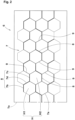
- FIG. 1 is a development of a tread portion 2, showing a tire 1 of the present embodiment.
- the tire 1 of the present embodiment has the tread portion 2 which comes into contact with a road surface during running.
- the tire 1 is suitable for use as, for example, a pneumatic tire for a passenger car that can be used in winter.
- the tire 1 is not limited to such a mode, and may be used as, for example, a heavy duty tire, a tire for a motorcycle, a non-pneumatic tire the interior of which is not filled with pressurized air, etc.
- the tread portion 2 includes, for example, a plurality of circumferential grooves 3 continuously extending in the tire circumferential direction, land portions 4 demarcated by the circumferential grooves 3, and a plurality of lateral grooves 5 traversing the land portions 4 in the tire axial direction. Accordingly, each of the land portions 4 of the present embodiment is divided into a plurality of blocks 6 by the circumferential grooves 3 and the lateral grooves 5.
- Such a tread portion 2 can generate a snow column shearing force with the circumferential grooves 3 and the lateral grooves 5, and the circumferential grooves 3 and the lateral grooves 5 can exhibit an edge effect. Therefore, the tread portion 2 of the present embodiment serves to improve steering stability during running on a snow road surface (hereinafter, referred to as "on-snow performance") of the tire 1 and steering stability during running on an ice road surface (hereinafter, referred to as "on-ice performance”) of the tire 1.
- a hexagonal sipe group 7 having a plurality of straight sipe pieces 7a arranged so as to form a plurality of hexagons H is provided on at least one of the blocks 6 of the tread portion 2 of the present embodiment.
- Such a tread portion 2 can exhibit an edge effect and a snow biting effect in the tire circumferential direction and the tire axial direction, and can improve the on-snow performance and the on-ice performance of the tire 1.
- a sipe is a slit having a width, of not greater than 2 mm, orthogonal to the longitudinal direction thereof.
- dimensions and the like of components of the tire 1 are values measured in a normal state.
- the "normal state” is a state where the tire 1 is fitted on a normal rim and adjusted to a normal internal pressure and no load is applied to the tire 1.
- the "normal rim” is a rim that is defined, in a standard system including a standard on which the tire 1 is based, by the standard for each tire, and is, for example, the "standard rim” in the JATMA standard, the "Design Rim” in the TRA standard, or the “Measuring Rim” in the ETRTO standard. If there is no standard system including a standard on which the tire 1 is based, the "normal rim” is a rim that is defined for each tire by the manufacturer or the like.
- the "normal internal pressure” is an air pressure that is defined, in a standard system including a standard on which the tire 1 is based, by the standard for each tire, and is the "maximum air pressure" in the JATMA standard, the maximum value indicated in the table "TIRE LOAD LIMITS AT VARIOUS COLD INFLATION PRESSURES" in the TRA standard, or the "INFLATION PRESSURE” in the ETRTO standard. If there is no standard system including a standard on which the tire 1 is based, the "normal internal pressure” is an air pressure that is defined for each tire by the manufacturer or the like.
- the present embodiment illustrates that the hexagonal sipe group 7 is provided on each of the blocks 6 closest to tread end Te sides, but the hexagonal sipe group 7 is not limited to such a mode, and may be provided on a land portion 4 other than the above blocks 6.
- each tread end Te is a ground contact position at the outermost side in the tire axial direction when a normal load is applied to the tire 1 in a normal state and the tire 1 is brought into contact with a flat surface at a camber angle of 0°.
- a tire equator C corresponds to the center position in the tire axial direction between a pair of the tread ends Te.
- the "normal load” is a load that is defined, in a standard system including a standard on which the tire 1 is based, by the standard for each tire, and is the "maximum load capacity" in the JATMA standard, the maximum value indicated in the table "TIRE LOAD LIMITS AT VARIOUS COLD INFLATION PRESSURES" in the TRA standard, or the "LOAD CAPACITY” in the ETRTO standard. If there is no standard system including a standard on which the tire 1 is based, the "normal load” is a load that is defined for each tire by the manufacturer or the like.
- FIG. 2 is an enlarged view of the block 6 on which the hexagonal sipe groups 7 are provided.
- each hexagonal sipe group 7 of the present embodiment includes first depth portions 8 and second depth portions 9 having a smaller depth in the tire radial direction than the first depth portions 8.
- the first depth portions 8 are represented by thicker lines than the second depth portions 9.
- Such a hexagonal sipe group 7 can maintain high stiffness, and can improve the braking performance on a dry road surface of the tire 1. Therefore, the tire 1 of the present embodiment can have improved on-snow performance, on-ice performance, and braking performance in a well-balanced manner.
- the hexagonal sipe group 7 includes a first hexagon H1 and a second hexagon H2 adjacent to each other, as the plurality of hexagons H.
- the plurality of sipe pieces 7a of the present embodiment include one first sipe piece 7b forming the first hexagon HI, one second sipe piece 7c forming the second hexagon H2, and a third sipe piece 7d connecting the first sipe piece 7b and the second sipe piece 7c.
- the first sipe piece 7b and the second sipe piece 7c preferably extend parallel to each other.
- the first sipe piece 7b and the second sipe piece 7c extend in the tire axial direction, for example.
- Each first depth portion 8 of the present embodiment is formed in a crank shape by the first sipe piece 7b, the second sipe piece 7c, and the third sipe piece 7d. Since each first depth portion 8 is bent in a crank shape, such a hexagonal sipe group 7 can exhibit an edge effect in the tire circumferential direction and the tire axial direction while suppressing an excessive decrease in the stiffness of the block 6.
- the first depth portion 8 is not limited to such a mode, and may be, for example, a portion having a large depth at a part of the sipe piece 7a.
- a plurality of the first depth portions 8 are preferably arranged so as to be spaced apart from each other in the tire circumferential direction.
- the directions of the cranks of a pair of first depth portions 8 adjacent to each other in the tire circumferential direction of the present embodiment are opposite to each other.
- the first depth portions 8 adjacent to each other in the tire circumferential direction are arranged so as to be displaced relative to each other in the tire axial direction. Therefore, the first depth portions 8 can suppress a decrease in the stiffness in the tire circumferential direction of the block 6 and can improve the braking performance of the tire 1.
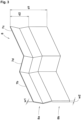
- FIG. 3 is a cross-sectional perspective view schematically showing the first depth portion 8.
- each first depth portion 8 of the present embodiment includes, in the tire radial direction, at least one bent portion 8a bent in the direction of a sipe width w1 thereof.
- Such first depth portions 8 can suppress a stiffness decrease by the bent portions 8a supporting each other, when a large external force is applied to the block 6, such as during braking.
- Each bent portion 8a may have, for example, a three-dimensional shape such as a so-called Miura fold structure.
- the sipe width w1 of each bent portion 8a is preferably not greater than 0.5 mm.
- Such bent portions 8a can reliably support each other when a large external force is applied to the block 6, such as during braking, and can improve the braking performance of the tire 1. From such a viewpoint, the sipe width w1 of the bent portion 8a is more preferably not greater than 0.3 mm.
- Each first depth portion 8 preferably includes, in the tire radial direction, a straight portion 8b extending in a straight manner on the inner side in the tire radial direction with respect to the bent portion 8a.
- a straight portion 8b can exhibit an edge effect and a snow biting effect even after the bent portion 8a disappears due to wear or the like, and can maintain the on-snow performance and the on-ice performance of the tire 1 for a long period of time.
- a sipe width w2 of the straight portion 8b of the present embodiment is larger than the sipe width w1 of the bent portion 8a. Since such a straight portion 8b has the large sipe width w2, the straight portion 8b can increase a snow column shearing force upon wear, and can improve the on-snow performance of the tire 1 upon wear.
- the sipe width w2 of the straight portion 8b is preferably not greater than 1.0 mm. Such a straight portion 8b can suppress an excessive decrease in the stiffness of the block 6 and can improve the on-snow performance, the on-ice performance, and the braking performance of the tire 1 upon wear in a well-balanced manner. From such a viewpoint, the sipe width w2 of the straight portion 8b is more preferably not greater than 0.7 mm.
- a depth d2 of the bent portion 8a is preferably 10% to 50% of a depth d1 of the first depth portion 8.
- the straight portion 8b can be inhibited from being excessively large, and the bent portion 8a can reliably exhibit an effect of supporting each other, so that a stiffness decrease can be suppressed.
- the straight portion 8b having the large sipe width w2 reliably appears when wear progresses to the extent that the second depth portion 9 disappears, so that the straight portion 8b serves to improve the on-snow performance of the tire 1 for a long period of time.
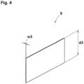
- FIG. 4 is a cross-sectional perspective view schematically showing the second depth portion 9.
- the second depth portion 9 of the present embodiment extends in a straight manner in the tire radial direction.
- Such a second depth portion 9 has a high snow compacting effect and can enhance a snow column shearing force.
- a sipe width w3 of the second depth portion 9 is preferably not greater than 0.5 mm.
- Such a second depth portion 9 can exhibit an edge effect and a water absorption effect by capillary action, and can improve the on-ice performance of the tire 1. From such a viewpoint, the sipe width w3 of the second depth portion 9 is more preferably not greater than 0.3 mm.
- the sipe width w3 of the second depth portion 9 is substantially equal to the sipe width w1 of the bent portion 8a.
- the "substantially equal to” means that a dimensional difference is within ⁇ 15%.
- Such a second depth portion 9 can cooperate with the bent portion 8a to exhibit an edge effect and a snow biting effect in a well-balanced manner in the tire circumferential direction and the tire axial direction.
- a depth d3 of the second depth portion 9 is preferably 10% to 50% of the depth d1 of the first depth portion 8.
- the second depth portion 9 can be inhibited from disappearing at the initial stage of wear.
- an excessive decrease in the stiffness of the block 6 can be suppressed.
- the depth d3 of the second depth portion 9 is substantially equal to the depth d2 of the bent portion 8a.
- the straight portion 8b, of the first depth portion 8, having the large sipe width w2 appears when the second depth portion 9 disappears due to wear, so that the on-snow performance, the on-ice performance, and the braking performance of the tire 1 can be improved for a long period of time.
- FIG. 5 is an enlarged view of the block 6 upon wear.
- the straight portions 8b of the first depth portions 8 appear, and the second depth portions 9 disappear. Since the first depth portions 8 adjacent to each other in the tire circumferential direction are arranged so as to be displaced relative to each other in the tire axial direction, such a block 6 can suppress a decrease in the stiffness in the tire circumferential direction of the block 6 upon wear and can improve the braking performance of the tire 1 upon wear.
- the present disclosure is as follows.
- a tire having a tread portion wherein a hexagonal sipe group having a plurality of straight sipe pieces arranged so as to form a plurality of hexagons is provided on the tread portion, and the hexagonal sipe group includes a first depth portion and a second depth portion having a smaller depth in a tire radial direction than the first depth portion.
- the hexagonal sipe group includes, as the plurality of hexagons, a first hexagon and a second hexagon adjacent to each other, the plurality of sipe pieces include one first sipe piece forming the first hexagon, one second sipe piece forming the second hexagon, and a third sipe piece connecting the first sipe piece and the second sipe piece, and the first depth portion is formed in a crank shape by the first sipe piece, the second sipe piece, and the third sipe piece.
- the first depth portion includes, in the tire radial direction, at least one bent portion bent in a direction orthogonal to a longitudinal direction of the sipe piece.
- the first depth portion includes, in the tire radial direction, a straight portion extending in a straight manner on an inner side in the tire radial direction with respect to the bent portion.
Landscapes
- Engineering & Computer Science (AREA)
- Mechanical Engineering (AREA)
- Tires In General (AREA)
Abstract
Description
- The present disclosure relates to a tire having a tread portion.
- Conventionally, a tire in which sipes are provided on a tread portion in order to improve on-snow performance and on-ice performance, is known. For example,
Japanese Laid-Open Patent Publication No. 2015-030414 - However, the tire of
Japanese Laid-Open Patent Publication No. 2015-030414 - The present disclosure has been made in view of the above circumstances, and a main object of the present disclosure is to provide a tire that can have improved on-snow performance, on-ice performance, and braking performance in a well-balanced manner.
- The present disclosure is directed to a tire having a tread portion, wherein a hexagonal sipe group having a plurality of straight sipe pieces arranged so as to form a plurality of hexagons is provided on the tread portion, and the hexagonal sipe group includes a first depth portion and a second depth portion having a smaller depth in a tire radial direction than the first depth portion.
- By having the above-described configuration, the tire of the present disclosure can have improved on-snow performance, on-ice performance, and braking performance in a well-balanced manner.
-
-
FIG. 1 is a development of a tread portion, showing an embodiment of the tire of the present disclosure; -
FIG. 2 is an enlarged view of a block on which hexagonal sipe groups are provided; -
FIG. 3 is a cross-sectional perspective view schematically showing a first depth portion; -
FIG. 4 is a cross-sectional perspective view schematically showing a second depth portion; and -
FIG. 5 is an enlarged view of the block upon wear. - Hereinafter, an embodiment of the present disclosure will be described in detail with reference to the drawings.
-
FIG. 1 is a development of a tread portion 2, showing a tire 1 of the present embodiment. As shown inFIG. 1 , the tire 1 of the present embodiment has the tread portion 2 which comes into contact with a road surface during running. The tire 1 is suitable for use as, for example, a pneumatic tire for a passenger car that can be used in winter. The tire 1 is not limited to such a mode, and may be used as, for example, a heavy duty tire, a tire for a motorcycle, a non-pneumatic tire the interior of which is not filled with pressurized air, etc. - The tread portion 2 includes, for example, a plurality of
circumferential grooves 3 continuously extending in the tire circumferential direction, land portions 4 demarcated by thecircumferential grooves 3, and a plurality oflateral grooves 5 traversing the land portions 4 in the tire axial direction. Accordingly, each of the land portions 4 of the present embodiment is divided into a plurality ofblocks 6 by thecircumferential grooves 3 and thelateral grooves 5. - Such a tread portion 2 can generate a snow column shearing force with the
circumferential grooves 3 and thelateral grooves 5, and thecircumferential grooves 3 and thelateral grooves 5 can exhibit an edge effect. Therefore, the tread portion 2 of the present embodiment serves to improve steering stability during running on a snow road surface (hereinafter, referred to as "on-snow performance") of the tire 1 and steering stability during running on an ice road surface (hereinafter, referred to as "on-ice performance") of the tire 1. - A
hexagonal sipe group 7 having a plurality ofstraight sipe pieces 7a arranged so as to form a plurality of hexagons H is provided on at least one of theblocks 6 of the tread portion 2 of the present embodiment. Such a tread portion 2 can exhibit an edge effect and a snow biting effect in the tire circumferential direction and the tire axial direction, and can improve the on-snow performance and the on-ice performance of the tire 1. - Here, in the present specification, a sipe is a slit having a width, of not greater than 2 mm, orthogonal to the longitudinal direction thereof. In addition, in the present specification, unless otherwise specified, dimensions and the like of components of the tire 1 are values measured in a normal state. In the case where the tire 1 is a pneumatic tire, the "normal state" is a state where the tire 1 is fitted on a normal rim and adjusted to a normal internal pressure and no load is applied to the tire 1.
- The "normal rim" is a rim that is defined, in a standard system including a standard on which the tire 1 is based, by the standard for each tire, and is, for example, the "standard rim" in the JATMA standard, the "Design Rim" in the TRA standard, or the "Measuring Rim" in the ETRTO standard. If there is no standard system including a standard on which the tire 1 is based, the "normal rim" is a rim that is defined for each tire by the manufacturer or the like.
- The "normal internal pressure" is an air pressure that is defined, in a standard system including a standard on which the tire 1 is based, by the standard for each tire, and is the "maximum air pressure" in the JATMA standard, the maximum value indicated in the table "TIRE LOAD LIMITS AT VARIOUS COLD INFLATION PRESSURES" in the TRA standard, or the "INFLATION PRESSURE" in the ETRTO standard. If there is no standard system including a standard on which the tire 1 is based, the "normal internal pressure" is an air pressure that is defined for each tire by the manufacturer or the like.
- The present embodiment illustrates that the
hexagonal sipe group 7 is provided on each of theblocks 6 closest to tread end Te sides, but thehexagonal sipe group 7 is not limited to such a mode, and may be provided on a land portion 4 other than theabove blocks 6. - Here, in the case where the tire 1 is a pneumatic tire, each tread end Te is a ground contact position at the outermost side in the tire axial direction when a normal load is applied to the tire 1 in a normal state and the tire 1 is brought into contact with a flat surface at a camber angle of 0°. A tire equator C corresponds to the center position in the tire axial direction between a pair of the tread ends Te.
- The "normal load" is a load that is defined, in a standard system including a standard on which the tire 1 is based, by the standard for each tire, and is the "maximum load capacity" in the JATMA standard, the maximum value indicated in the table "TIRE LOAD LIMITS AT VARIOUS COLD INFLATION PRESSURES" in the TRA standard, or the "LOAD CAPACITY" in the ETRTO standard. If there is no standard system including a standard on which the tire 1 is based, the "normal load" is a load that is defined for each tire by the manufacturer or the like.
-
FIG. 2 is an enlarged view of theblock 6 on which thehexagonal sipe groups 7 are provided. As shown inFIG. 2 , eachhexagonal sipe group 7 of the present embodiment includesfirst depth portions 8 andsecond depth portions 9 having a smaller depth in the tire radial direction than thefirst depth portions 8. InFIG. 2 , for ease of understanding, thefirst depth portions 8 are represented by thicker lines than thesecond depth portions 9. - Such a
hexagonal sipe group 7 can maintain high stiffness, and can improve the braking performance on a dry road surface of the tire 1. Therefore, the tire 1 of the present embodiment can have improved on-snow performance, on-ice performance, and braking performance in a well-balanced manner. - As a more preferable mode, the
hexagonal sipe group 7 includes a first hexagon H1 and a second hexagon H2 adjacent to each other, as the plurality of hexagons H. The plurality ofsipe pieces 7a of the present embodiment include onefirst sipe piece 7b forming the first hexagon HI, onesecond sipe piece 7c forming the second hexagon H2, and athird sipe piece 7d connecting thefirst sipe piece 7b and thesecond sipe piece 7c. Thefirst sipe piece 7b and thesecond sipe piece 7c preferably extend parallel to each other. Thefirst sipe piece 7b and thesecond sipe piece 7c extend in the tire axial direction, for example. - Each
first depth portion 8 of the present embodiment is formed in a crank shape by thefirst sipe piece 7b, thesecond sipe piece 7c, and thethird sipe piece 7d. Since eachfirst depth portion 8 is bent in a crank shape, such ahexagonal sipe group 7 can exhibit an edge effect in the tire circumferential direction and the tire axial direction while suppressing an excessive decrease in the stiffness of theblock 6. Thefirst depth portion 8 is not limited to such a mode, and may be, for example, a portion having a large depth at a part of thesipe piece 7a. - A plurality of the
first depth portions 8 are preferably arranged so as to be spaced apart from each other in the tire circumferential direction. The directions of the cranks of a pair offirst depth portions 8 adjacent to each other in the tire circumferential direction of the present embodiment are opposite to each other. As for suchfirst depth portions 8, thefirst depth portions 8 adjacent to each other in the tire circumferential direction are arranged so as to be displaced relative to each other in the tire axial direction. Therefore, thefirst depth portions 8 can suppress a decrease in the stiffness in the tire circumferential direction of theblock 6 and can improve the braking performance of the tire 1. -
FIG. 3 is a cross-sectional perspective view schematically showing thefirst depth portion 8. As shown inFIG. 3 , eachfirst depth portion 8 of the present embodiment includes, in the tire radial direction, at least onebent portion 8a bent in the direction of a sipe width w1 thereof. Suchfirst depth portions 8 can suppress a stiffness decrease by thebent portions 8a supporting each other, when a large external force is applied to theblock 6, such as during braking. Eachbent portion 8a may have, for example, a three-dimensional shape such as a so-called Miura fold structure. - The sipe width w1 of each
bent portion 8a is preferably not greater than 0.5 mm.Such bent portions 8a can reliably support each other when a large external force is applied to theblock 6, such as during braking, and can improve the braking performance of the tire 1. From such a viewpoint, the sipe width w1 of thebent portion 8a is more preferably not greater than 0.3 mm. - Each
first depth portion 8 preferably includes, in the tire radial direction, astraight portion 8b extending in a straight manner on the inner side in the tire radial direction with respect to thebent portion 8a. Such astraight portion 8b can exhibit an edge effect and a snow biting effect even after thebent portion 8a disappears due to wear or the like, and can maintain the on-snow performance and the on-ice performance of the tire 1 for a long period of time. - A sipe width w2 of the
straight portion 8b of the present embodiment is larger than the sipe width w1 of thebent portion 8a. Since such astraight portion 8b has the large sipe width w2, thestraight portion 8b can increase a snow column shearing force upon wear, and can improve the on-snow performance of the tire 1 upon wear. - The sipe width w2 of the
straight portion 8b is preferably not greater than 1.0 mm. Such astraight portion 8b can suppress an excessive decrease in the stiffness of theblock 6 and can improve the on-snow performance, the on-ice performance, and the braking performance of the tire 1 upon wear in a well-balanced manner. From such a viewpoint, the sipe width w2 of thestraight portion 8b is more preferably not greater than 0.7 mm. - A depth d2 of the
bent portion 8a is preferably 10% to 50% of a depth d1 of thefirst depth portion 8. By setting the depth d2 of thebent portion 8a to be not less than 10% of the depth d1 of thefirst depth portion 8, thestraight portion 8b can be inhibited from being excessively large, and thebent portion 8a can reliably exhibit an effect of supporting each other, so that a stiffness decrease can be suppressed. By setting the depth d2 of thebent portion 8a to be not greater than 50% of the depth d1 of thefirst depth portion 8, thestraight portion 8b having the large sipe width w2 reliably appears when wear progresses to the extent that thesecond depth portion 9 disappears, so that thestraight portion 8b serves to improve the on-snow performance of the tire 1 for a long period of time. -
FIG. 4 is a cross-sectional perspective view schematically showing thesecond depth portion 9. As shown inFIG. 4 , thesecond depth portion 9 of the present embodiment extends in a straight manner in the tire radial direction. Such asecond depth portion 9 has a high snow compacting effect and can enhance a snow column shearing force. - A sipe width w3 of the
second depth portion 9 is preferably not greater than 0.5 mm. Such asecond depth portion 9 can exhibit an edge effect and a water absorption effect by capillary action, and can improve the on-ice performance of the tire 1. From such a viewpoint, the sipe width w3 of thesecond depth portion 9 is more preferably not greater than 0.3 mm. - As shown in
FIG. 3 andFIG. 4 , preferably, the sipe width w3 of thesecond depth portion 9 is substantially equal to the sipe width w1 of thebent portion 8a. Here, in the present specification, the "substantially equal to" means that a dimensional difference is within ±15%. Such asecond depth portion 9 can cooperate with thebent portion 8a to exhibit an edge effect and a snow biting effect in a well-balanced manner in the tire circumferential direction and the tire axial direction. - A depth d3 of the
second depth portion 9 is preferably 10% to 50% of the depth d1 of thefirst depth portion 8. By setting the depth d3 of thesecond depth portion 9 to be not less than 10% of the depth d1 of thefirst depth portion 8, thesecond depth portion 9 can be inhibited from disappearing at the initial stage of wear. By setting the depth d3 of thesecond depth portion 9 to be not greater than 50% of the depth d1 of thefirst depth portion 8, an excessive decrease in the stiffness of theblock 6 can be suppressed. - Preferably, the depth d3 of the
second depth portion 9 is substantially equal to the depth d2 of thebent portion 8a. In such ahexagonal sipe group 7, thestraight portion 8b, of thefirst depth portion 8, having the large sipe width w2 appears when thesecond depth portion 9 disappears due to wear, so that the on-snow performance, the on-ice performance, and the braking performance of the tire 1 can be improved for a long period of time. -
FIG. 5 is an enlarged view of theblock 6 upon wear. As shown inFIG. 5 , in eachblock 6 of the present embodiment, upon wear, thestraight portions 8b of thefirst depth portions 8 appear, and thesecond depth portions 9 disappear. Since thefirst depth portions 8 adjacent to each other in the tire circumferential direction are arranged so as to be displaced relative to each other in the tire axial direction, such ablock 6 can suppress a decrease in the stiffness in the tire circumferential direction of theblock 6 upon wear and can improve the braking performance of the tire 1 upon wear. - Although the particularly preferred embodiment of the present disclosure have been described in detail above, the present disclosure is not limited to the above-described embodiment, and various modifications can be made to implement the present disclosure.
- The present disclosure is as follows.
- A tire having a tread portion, wherein a hexagonal sipe group having a plurality of straight sipe pieces arranged so as to form a plurality of hexagons is provided on the tread portion, and the hexagonal sipe group includes a first depth portion and a second depth portion having a smaller depth in a tire radial direction than the first depth portion.
- The tire according to Present Disclosure 1, wherein the hexagonal sipe group includes, as the plurality of hexagons, a first hexagon and a second hexagon adjacent to each other, the plurality of sipe pieces include one first sipe piece forming the first hexagon, one second sipe piece forming the second hexagon, and a third sipe piece connecting the first sipe piece and the second sipe piece, and the first depth portion is formed in a crank shape by the first sipe piece, the second sipe piece, and the third sipe piece.
- The tire according to Present Disclosure 2, wherein a plurality of the first depth portions are arranged so as to be spaced apart from each other in a tire circumferential direction, and directions of cranks of a pair of the first depth portions adjacent to each other in the tire circumferential direction are opposite to each other.
- The tire according to any one of Present Disclosures 1 to 3, wherein the depth of the second depth portion is 10% to 50% of a depth of the first depth portion.
- The tire according to any one of Present Disclosures 1 to 4, wherein the first depth portion includes, in the tire radial direction, at least one bent portion bent in a direction orthogonal to a longitudinal direction of the sipe piece.
- The tire according to
Present Disclosure 5, wherein the first depth portion includes, in the tire radial direction, a straight portion extending in a straight manner on an inner side in the tire radial direction with respect to the bent portion. - The tire according to
Present Disclosure 6, wherein a sipe width of the straight portion is larger than a sipe width of the bent portion. - The tire according to any one of Present Disclosures 1 to 7, wherein the second depth portion extends in a straight manner in the tire radial direction.
Claims (8)
- A tire (1) having a tread portion (2), whereina hexagonal sipe group (7) having a plurality of straight sipe pieces (7a) arranged so as to form a plurality of hexagons (H) is provided on the tread portion (2), andthe hexagonal sipe group (7) includes a first depth portion (8) and a second depth portion (9) having a smaller depth (d3) in a tire radial direction than the first depth portion (8).
- The tire (1) according to claim 1, whereinthe hexagonal sipe group (7) includes, as the plurality of hexagons (H), a first hexagon (HI) and a second hexagon (H2) adjacent to each other,the plurality of sipe pieces (7a) include one first sipe piece (7b) forming the first hexagon (HI), one second sipe piece (7c) forming the second hexagon (H2), and a third sipe piece (7d) connecting the first sipe piece (7b) and the second sipe piece (7c), andthe first depth portion (8) is formed in a crank shape by the first sipe piece (7b), the second sipe piece (7c), and the third sipe piece (7d).
- The tire (1) according to claim 2, whereina plurality of the first depth portions (8) are arranged so as to be spaced apart from each other in a tire circumferential direction, anddirections of cranks of a pair of the first depth portions (8) adjacent to each other in the tire circumferential direction are opposite to each other.
- The tire (1) according to any one of claims 1 to 3, wherein the depth (d3) of the second depth portion (9) is 10% to 50% of a depth (d1) of the first depth portion (8).
- The tire (1) according to any one of claims 1 to 4, wherein the first depth portion (8) includes, in the tire radial direction, at least one bent portion (8a) bent in a direction orthogonal to a longitudinal direction of the sipe piece (7a).
- The tire (1) according to claim 5, wherein the first depth portion (8) includes, in the tire radial direction, a straight portion (8b) extending in a straight manner on an inner side in the tire radial direction with respect to the bent portion (8a).
- The tire (1) according to claim 6, wherein a sipe width (w2) of the straight portion (8b) is larger than a sipe width (w1) of the bent portion (8a).
- The tire (1) according to any one of claims 1 to 7, wherein the second depth portion (9) extends in a straight manner in the tire radial direction.
Applications Claiming Priority (1)
| Application Number | Priority Date | Filing Date | Title |
|---|---|---|---|
| JP2021208579A JP2023093140A (en) | 2021-12-22 | 2021-12-22 | tire |
Publications (1)
| Publication Number | Publication Date |
|---|---|
| EP4201710A1 true EP4201710A1 (en) | 2023-06-28 |
Family
ID=84421614
Family Applications (1)
| Application Number | Title | Priority Date | Filing Date |
|---|---|---|---|
| EP22211588.3A Pending EP4201710A1 (en) | 2021-12-22 | 2022-12-06 | Tire |
Country Status (2)
| Country | Link |
|---|---|
| EP (1) | EP4201710A1 (en) |
| JP (1) | JP2023093140A (en) |
Citations (5)
| Publication number | Priority date | Publication date | Assignee | Title |
|---|---|---|---|---|
| EP0934836A2 (en) * | 1998-02-05 | 1999-08-11 | Continental Aktiengesellschaft | Vehicle tyre and tyre vulcanization mould with blades |
| EP0968847A2 (en) * | 1998-07-01 | 2000-01-05 | Continental Aktiengesellschaft | Vehicle tyre |
| EP0974439A2 (en) * | 1998-07-22 | 2000-01-26 | Continental Aktiengesellschaft | Process for the manufacture of a honeycomb-shaped pattern of lamellas for a tyre vulcanizing mould, mould and tyre |
| JP2015030414A (en) | 2013-08-05 | 2015-02-16 | 住友ゴム工業株式会社 | Pneumatic tire |
| JP2016037083A (en) * | 2014-08-05 | 2016-03-22 | 横浜ゴム株式会社 | Pneumatic tire |
-
2021
- 2021-12-22 JP JP2021208579A patent/JP2023093140A/en active Pending
-
2022
- 2022-12-06 EP EP22211588.3A patent/EP4201710A1/en active Pending
Patent Citations (5)
| Publication number | Priority date | Publication date | Assignee | Title |
|---|---|---|---|---|
| EP0934836A2 (en) * | 1998-02-05 | 1999-08-11 | Continental Aktiengesellschaft | Vehicle tyre and tyre vulcanization mould with blades |
| EP0968847A2 (en) * | 1998-07-01 | 2000-01-05 | Continental Aktiengesellschaft | Vehicle tyre |
| EP0974439A2 (en) * | 1998-07-22 | 2000-01-26 | Continental Aktiengesellschaft | Process for the manufacture of a honeycomb-shaped pattern of lamellas for a tyre vulcanizing mould, mould and tyre |
| JP2015030414A (en) | 2013-08-05 | 2015-02-16 | 住友ゴム工業株式会社 | Pneumatic tire |
| JP2016037083A (en) * | 2014-08-05 | 2016-03-22 | 横浜ゴム株式会社 | Pneumatic tire |
Also Published As
| Publication number | Publication date |
|---|---|
| JP2023093140A (en) | 2023-07-04 |
Similar Documents
| Publication | Publication Date | Title |
|---|---|---|
| US9994077B2 (en) | Pneumatic tire | |
| US10894446B2 (en) | Tire | |
| EP3153334B1 (en) | Tire | |
| US10836215B2 (en) | Tire | |
| US11198330B2 (en) | Tire | |
| EP2261064B1 (en) | Pneumatic tire | |
| EP2514608B1 (en) | Pneumatic tire | |
| EP2578419B1 (en) | Pneumatic tire | |
| US10668775B2 (en) | Tire | |
| US11192404B2 (en) | Tyre | |
| US10118445B2 (en) | Pneumatic tire | |
| US10272725B2 (en) | Pneumatic tire | |
| CN108688411B (en) | Pneumatic tire | |
| EP3290233A1 (en) | Tire | |
| US11505005B2 (en) | Pneumatic tire | |
| CN106985619B (en) | Tyre for vehicle wheels | |
| EP3388254B1 (en) | Tire | |
| EP3552846B1 (en) | Tyre | |
| EP3970996B1 (en) | Tire | |
| EP4201710A1 (en) | Tire | |
| EP3461657A1 (en) | Tire | |
| JP2023092234A (en) | tire | |
| EP2848433B1 (en) | Pneumatic tire |
Legal Events
| Date | Code | Title | Description |
|---|---|---|---|
| PUAI | Public reference made under article 153(3) epc to a published international application that has entered the european phase |
Free format text: ORIGINAL CODE: 0009012 |
|
| STAA | Information on the status of an ep patent application or granted ep patent |
Free format text: STATUS: THE APPLICATION HAS BEEN PUBLISHED |
|
| AK | Designated contracting states |
Kind code of ref document: A1 Designated state(s): AL AT BE BG CH CY CZ DE DK EE ES FI FR GB GR HR HU IE IS IT LI LT LU LV MC ME MK MT NL NO PL PT RO RS SE SI SK SM TR |
|
| STAA | Information on the status of an ep patent application or granted ep patent |
Free format text: STATUS: REQUEST FOR EXAMINATION WAS MADE |
|
| 17P | Request for examination filed |
Effective date: 20231013 |
|
| RBV | Designated contracting states (corrected) |
Designated state(s): AL AT BE BG CH CY CZ DE DK EE ES FI FR GB GR HR HU IE IS IT LI LT LU LV MC ME MK MT NL NO PL PT RO RS SE SI SK SM TR |
|
| P01 | Opt-out of the competence of the unified patent court (upc) registered |
Effective date: 20240327 |
|
| GRAP | Despatch of communication of intention to grant a patent |
Free format text: ORIGINAL CODE: EPIDOSNIGR1 |
|
| STAA | Information on the status of an ep patent application or granted ep patent |
Free format text: STATUS: GRANT OF PATENT IS INTENDED |