EP4201660A1 - Procédé de fabrication d'une pale d'éolienne - Google Patents
Procédé de fabrication d'une pale d'éolienne Download PDFInfo
- Publication number
- EP4201660A1 EP4201660A1 EP21216387.7A EP21216387A EP4201660A1 EP 4201660 A1 EP4201660 A1 EP 4201660A1 EP 21216387 A EP21216387 A EP 21216387A EP 4201660 A1 EP4201660 A1 EP 4201660A1
- Authority
- EP
- European Patent Office
- Prior art keywords
- blade
- fiber lay
- outer recess
- blade sections
- load
- Prior art date
- Legal status (The legal status is an assumption and is not a legal conclusion. Google has not performed a legal analysis and makes no representation as to the accuracy of the status listed.)
- Pending
Links
- 238000000034 method Methods 0.000 title claims abstract description 41
- 238000004519 manufacturing process Methods 0.000 title claims abstract description 27
- 239000000835 fiber Substances 0.000 claims abstract description 95
- 239000011347 resin Substances 0.000 claims description 28
- 229920005989 resin Polymers 0.000 claims description 28
- 230000002787 reinforcement Effects 0.000 claims description 10
- 238000005304 joining Methods 0.000 claims description 9
- 229920000049 Carbon (fiber) Polymers 0.000 claims description 8
- 239000004917 carbon fiber Substances 0.000 claims description 8
- 239000003365 glass fiber Substances 0.000 claims description 7
- 238000005266 casting Methods 0.000 claims description 6
- 239000000853 adhesive Substances 0.000 claims description 3
- 230000001070 adhesive effect Effects 0.000 claims description 3
- 239000000463 material Substances 0.000 abstract description 4
- POIUWJQBRNEFGX-XAMSXPGMSA-N cathelicidin Chemical compound C([C@@H](C(=O)N[C@@H](CCCNC(N)=N)C(=O)N[C@@H](CCCCN)C(=O)N[C@@H](CO)C(=O)N[C@@H](CCCCN)C(=O)N[C@@H](CCC(O)=O)C(=O)N[C@@H](CCCCN)C(=O)N[C@@H]([C@@H](C)CC)C(=O)NCC(=O)N[C@@H](CCCCN)C(=O)N[C@@H](CCC(O)=O)C(=O)N[C@@H](CC=1C=CC=CC=1)C(=O)N[C@@H](CCCCN)C(=O)N[C@@H](CCCNC(N)=N)C(=O)N[C@@H]([C@@H](C)CC)C(=O)N[C@@H](C(C)C)C(=O)N[C@@H](CCC(N)=O)C(=O)N[C@@H](CCCNC(N)=N)C(=O)N[C@@H]([C@@H](C)CC)C(=O)N[C@@H](CCCCN)C(=O)N[C@@H](CC(O)=O)C(=O)N[C@@H](CC=1C=CC=CC=1)C(=O)N[C@@H](CC(C)C)C(=O)N[C@@H](CCCNC(N)=N)C(=O)N[C@@H](CC(N)=O)C(=O)N[C@@H](CC(C)C)C(=O)N[C@@H](C(C)C)C(=O)N1[C@@H](CCC1)C(=O)N[C@@H](CCCNC(N)=N)C(=O)N[C@@H]([C@@H](C)O)C(=O)N[C@@H](CCC(O)=O)C(=O)N[C@@H](CO)C(O)=O)NC(=O)[C@H](CC=1C=CC=CC=1)NC(=O)[C@H](CC(O)=O)NC(=O)CNC(=O)[C@H](CC(C)C)NC(=O)[C@@H](N)CC(C)C)C1=CC=CC=C1 POIUWJQBRNEFGX-XAMSXPGMSA-N 0.000 description 8
- 238000001802 infusion Methods 0.000 description 4
- 239000011162 core material Substances 0.000 description 2
- VNWKTOKETHGBQD-UHFFFAOYSA-N methane Chemical compound C VNWKTOKETHGBQD-UHFFFAOYSA-N 0.000 description 2
- 238000009755 vacuum infusion Methods 0.000 description 2
- 230000001419 dependent effect Effects 0.000 description 1
- 239000002657 fibrous material Substances 0.000 description 1
- 238000003306 harvesting Methods 0.000 description 1
- 238000012986 modification Methods 0.000 description 1
- 230000004048 modification Effects 0.000 description 1
- 230000003014 reinforcing effect Effects 0.000 description 1
- 238000007789 sealing Methods 0.000 description 1
Images


Classifications
-
- B—PERFORMING OPERATIONS; TRANSPORTING
- B29—WORKING OF PLASTICS; WORKING OF SUBSTANCES IN A PLASTIC STATE IN GENERAL
- B29D—PRODUCING PARTICULAR ARTICLES FROM PLASTICS OR FROM SUBSTANCES IN A PLASTIC STATE
- B29D99/00—Subject matter not provided for in other groups of this subclass
- B29D99/0025—Producing blades or the like, e.g. blades for turbines, propellers, or wings
- B29D99/0028—Producing blades or the like, e.g. blades for turbines, propellers, or wings hollow blades
-
- Y—GENERAL TAGGING OF NEW TECHNOLOGICAL DEVELOPMENTS; GENERAL TAGGING OF CROSS-SECTIONAL TECHNOLOGIES SPANNING OVER SEVERAL SECTIONS OF THE IPC; TECHNICAL SUBJECTS COVERED BY FORMER USPC CROSS-REFERENCE ART COLLECTIONS [XRACs] AND DIGESTS
- Y02—TECHNOLOGIES OR APPLICATIONS FOR MITIGATION OR ADAPTATION AGAINST CLIMATE CHANGE
- Y02E—REDUCTION OF GREENHOUSE GAS [GHG] EMISSIONS, RELATED TO ENERGY GENERATION, TRANSMISSION OR DISTRIBUTION
- Y02E10/00—Energy generation through renewable energy sources
- Y02E10/70—Wind energy
- Y02E10/72—Wind turbines with rotation axis in wind direction
-
- Y—GENERAL TAGGING OF NEW TECHNOLOGICAL DEVELOPMENTS; GENERAL TAGGING OF CROSS-SECTIONAL TECHNOLOGIES SPANNING OVER SEVERAL SECTIONS OF THE IPC; TECHNICAL SUBJECTS COVERED BY FORMER USPC CROSS-REFERENCE ART COLLECTIONS [XRACs] AND DIGESTS
- Y02—TECHNOLOGIES OR APPLICATIONS FOR MITIGATION OR ADAPTATION AGAINST CLIMATE CHANGE
- Y02P—CLIMATE CHANGE MITIGATION TECHNOLOGIES IN THE PRODUCTION OR PROCESSING OF GOODS
- Y02P70/00—Climate change mitigation technologies in the production process for final industrial or consumer products
- Y02P70/50—Manufacturing or production processes characterised by the final manufactured product
Definitions
- the present invention relates to a method for manufacturing a wind turbine blade.
- wind harvest and, thus, energy production of a wind turbine at a given site depends on the rotor diameter. With a larger rotor diameter and, hence, larger blade sizes, a larger area can be swept by the blades. Current blade lengths reach 100 meter and more. Manufacturing and transporting large wind turbine blades are becoming increasingly difficult for increasing blade sizes. Therefore, wind turbine blades are, for example, manufactured section-wise and joined in a later production step, as proposed in EP 3 747 639 A1 . However, assembling a wind turbine blade from two or more blade sections in an efficient manner and, at the same time, providing a sufficient strength of the blade to withstand forces acting on the blade during operation of the wind turbine is challenging.
- the wind turbine blade comprises a load-carrying beam extending in a longitudinal direction of the blade and having a predetermined total length.
- the method comprises the steps:
- the blade is produced from at least two blade sections allowing an easier manufacture of even very large blades.
- the at least two blade sections are pre-manufactured and the load-carrying beam is implemented in a subsequent production step.
- the at least two blade sections are pre-manufactured such that they comprise a recess for later adding the fiber lay-up for the load-carrying beam.
- the at least two blade sections can be positioned and aligned with each other without the presence of the load-carrying beam or portions of the load-carrying beam.
- handling of the at least two blade sections is simplified.
- the method comprises, in particular, the step of providing the at least two pre-manufactured blade sections each comprising a shell portion with an outer recess.
- the at least two blade sections are at least two longitudinal blade sections dividing the blade lengthwise.
- the at least two blade sections comprise, in particular, at least one inboard blade section and at least one outboard blade section.
- the at least two blade sections are configured to form, in the assembled state, the entire blade.
- the at least two blade sections are, in particular, pre-manufactured.
- the at least two blade sections are, for example, pre-casted.
- Pre-manufacturing the at least two blade sections is, for example, carried out at a first production site.
- Aligning and joining the at least two blade sections is, for example, carried out at a second production site different and/or located remote from the first production site.
- each of the at least two blade sections extends, in particular, in the longitudinal direction of the blade. Further, the overall outer recess of the blade sections in the aligned state, extends, in particular, in the longitudinal direction of the blade.
- the aligned state is, in particular, the aligned state of the bade sections.
- the at least two blade sections are, in particular, aligned with each other such that their outer recesses are aligned with each other and form the overall outer recess.
- the at least two blade sections are, in particular, aligned with each other by using an alignment tool and/or placing each of them on a support structure.
- the wind turbine blade is provided to become part of a rotor of a wind turbine.
- the wind turbine is an apparatus to convert the wind's kinetic energy into electrical energy.
- the wind turbine comprises, for example, the rotor having one or more of the blades connected each to a hub, a nacelle including a generator, and a tower holding, at its top end, the nacelle.
- the tower of the wind turbine may be connected to a foundation of the wind turbine such as a monopile or concrete foundation in the seabed or ground.
- the blade In the installed state of the wind turbine, the blade, e.g., a root portion of the blade, is, for example fixedly or rotatably connected to the hub.
- the wind turbine blade is, for example, directly bolted to the hub, or is connected via a pitch bearing to the hub.
- the pitch bearing is configured to adjust the angle of attack of the blade according to the wind speed to control the rotational speed of the blade.
- the outer surface of the wind turbine blade has an aerodynamically shaped cross section (airfoil).
- the aerodynamically shaped cross section of the wind turbine blade comprises, for example, a pressure side (upwind side) and a suction side (downwind side).
- the pressure side and the suction side are connected with each other at a leading edge and a trailing edge.
- the blade shell of the blade sections is, for example, manufactured from fiber-reinforced resin laminate by infusing plies of fiber material in a mold with a resin and curing the resin.
- the blade shell is, for example, manufactured by vacuum-infusion of resin into a fiber lay-up and curing the resin.
- the blade shell may also be manufactured by a different method.
- the blade shell has, in particular, an outer surface and an inner surface, wherein the outer surface defines the aerodynamic profile of the blade, and the inner surface defines an inner cavity of the blade.
- the blade includes at least one load-carrying beam.
- the load-carrying beam In the manufactured state of the blade, the load-carrying beam is, in particular, embedded in the blade shell.
- the load-carrying beam is a structural element reinforcing the blade shell and/or taking up mechanical load during operation of the wind turbine.
- the blade may comprise two or more load-carrying beams.
- each blade section may comprise, for example, two or more outer recesses such that two or more overall outer recesses are formed in the aligned state of the blade sections.
- Each of the two or more overall outer recesses extends in the longitudinal direction of the blade and is configured to receive a fiber lay-up for forming one of the two or more load-carrying beams.
- the at least two blade sections are aligned with each other in a state in which their outer recesses are vacant.
- the at least two blade sections are aligned with each other in a state in which their outer recesses are empty and do not comprise the load-carrying beam or portions of the load-carrying beam.
- step b) the fiber lay-up for the entire load-carrying beam is arranged in the overall outer recess and/or the fiber lay-up is arranged in the overall outer recess such that the arranged fiber lay-up has the predetermined total length.
- a continuous load-carrying beam without discontinuities at a joint can be provided which leads to a high structural strength of the load-carrying beam.
- the fiber lay-up includes a dry fiber lay-up, a semi-dry fiber lay-up and/or a pre-impregnated fiber lay-up.
- a dry fiber lay-up is, in particular, a fiber lay-up without any resin.
- a semi-dry fiber lay-up and a pre-impregnated fiber lay-up is, in particular, a fiber lay-up including resin in an uncured and/or semi-cured stage.
- the overall outer recess forms a mold for casting the load-carrying beam.
- the outer recess of the blade shell itself provides a mold for casting the laminate for forming the load-carrying beam.
- the load-carrying beam is casted and at the same time joined with the blade shell, in particular with a surface of the outer recess of the blade shell.
- the fiber lay-up is, for example, infused with resin in the mold formed by the outer recess and then cured.
- the method includes the steps of covering the fiber lay-up with a vacuum bag, infusing the fiber lay-up with resin and/or curing the resin.
- the fiber lay-up is, for example, infused with resin in a vacuum-induced infusion process.
- the resin is, for example, cured by applying heat.
- heat blankets may be applied on the exposed portion of the fiber lay-up arranged in the outer recess.
- the fiber lay-up being a semi-dry and/or pre-impregnated fiber lay-up already containing resin
- the step of (covering the fiber lay-up with a vacuum bag and) curing the resin may be carried out but not the step of infusing further resin.
- the fiber lay-up includes a pre-casted fiber lay-up.
- the fiber lay-up may include the pre-casted fiber lay-up in addition to a dry, semi-dry and/or pre-impregnated fiber lay-up.
- resin infusion and/or curing of the dry, semi-dry and/or pre-impregnated fiber lay-up may be applied to join the pre-casted fiber lay-up with an inner surface of the outer recess of the blade shell.
- the fiber lay-up may include only the pre-casted fiber lay-up but no additional dry, semi-dry and/or pre-impregnated fiber lay-up.
- step b) includes applying an adhesive in the overall outer recess and/or on the pre-casted fiber lay-up before arranging the fiber lay-up in the overall outer recess.
- the load-carrying beam is a spar cap, a leading-edge reinforcement beam or a trailing-edge reinforcement beam.
- the spar cap is one of the key structures inside a rotor blade and takes up most of the mechanical load of the blade during operation of the wind turbine. Hence, a high stiffness of the spar cap is essential for rotor blades of extreme length. Therefore, manufacturing a spar cap without discontinuities in the material is of advantageous for the structural integrity of the blade.
- the fiber lay-up includes carbon fibers and/or glass fibers.
- Carbon fibers are lighter by volume (e.g., by about 30%) than glass fibers. Further, carbon fibers provide higher tensile strength and higher compressive strength than glass fibers.
- carbon fiber reinforcement in spar caps is an efficient way to reduce the overall weight to length ratio and increase the blade stiffness.
- the method includes the step of casting the at least two blade sections by using a respective mold including a protrusion at an inner mold surface for forming the outer recess.
- the protrusion may be either integrated in the mold geometry (i.e. the mold (portion) and the protrusion are a one-piece element) or may be added as an add-on insert to the mold surface.
- the at least two blade sections include at least an inboard blade section comprising a root portion and an outboard blade section comprising a tip portion, and/or the at least two blade sections are aligned with each other by performing a global root to tip alignment.
- the method includes the step of joining the at least two blade sections with each other.
- the at least two blade sections may be joined with each other, for example, from inside the blade cavity.
- the at least two blade sections may, for example, be joined with each other by using a mandrel tool comprising a dry, semi-dry and/or pre-impregnated fiber lay-up.
- the mandrel tool is, for example, inserted into a first one of the at least two blade sections. Further, an adjacent one of the first one of the at least two blade sections is aligned with the first one such that the adjacent one accommodates the mandrel tool.
- the at least two blade sections may be joined with each other, in particular, after step b) of arranging the fiber lay-up in the overall outer recess. Furthermore, the at least two blade sections may be joined with each other, for example, after or in parallel with infusing the fiber lay-up with resin and/or curing the resin.
- each of the at least two blade sections comprises a shear web portion, and joining the at least two blade sections with each other includes connecting the shear web portions of the at least two blade sections with each other.
- the shear web (portion) is, in particular, a spar web (portion).
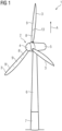
- Fig. 1 shows a wind turbine 1 according to an embodiment.
- the wind turbine 1 comprises a rotor 2 having one or more blades 3, 3' connected to a hub 4.
- the hub 4 is connected to a generator (not shown) arranged inside a nacelle 5.
- the blades 3 are driven by wind to rotate and the wind's kinetic energy is converted into electrical energy by the generator in the nacelle 5.
- the nacelle 5 is arranged at the upper end of a tower 6 of the wind turbine 1.
- the tower 6 is erected on a foundation 7 such as a concrete foundation or a monopile driven into the ground or seabed.
- one or more of the blades 3 of the wind turbine 1 are manufactured from at least two individual blade sections 8, 9.
- the at least two individual blade sections 8, 9 are dividing the blade 3 in a longitudinal direction A of the blade 3.
- the two or more blade sections 8, 9 are, in particular, pre-manufactured, positioned next to each other, accurately aligned with each other and finally joined with each other to form the manufactured blade 3.
- a blade 3 in Fig. 1 is shown to be assembled from two individual blade sections 8, 9.
- a blade 3' in Fig. 1 is shown to be assembled from three individual blade sections 8', 9', 9".
- one or more of the blades 3, 3' may also be manufactured from more than three individual blade sections.
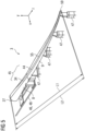
- Fig. 2 shows a perspective view of a portion of the wind turbine blade 3 of the wind turbine 1 of Fig. 1 according to an embodiment of the invention.
- the wind turbine blade 3 is sectionally cut from two sides running perpendicular to a longitudinal axis A of the blade 3.
- the wind turbine blade 3 As the wind turbine blade 3 is assembled from at least two individual blade sections 8 and 9, the wind turbine blade 3 comprises a shell 10 including several shell portions 11, 12.
- each of the at least two blade sections 8 and 9 comprises a shell portion 11, 12 which are joined together by means of a shell joint 13.
- the wind turbine blade 3 comprises a spar web 14.
- the spar web 14 is shown having a first spar web portion 15 and a second spar web portion 16.
- each of the at least two blade sections 8 and 9 comprises a respective spar web portion 15, 16.
- the first spar web portion 15 and the second spar web portion 16 are shown to be separated from one another by means of a gap 17.
- the gap 17 has the purpose of enabling joining the first shell portion 11 with the second shell portion 12 by means of the shell joint 13.
- the gap 17 may afterwards be closed by means of a third spar web portion which is not shown in this illustration.
- the wind turbine blade 3 comprises two spar caps 18, 19.
- the two spar caps 18, 19 are connected to one another by means of the spar web 14.
- the shell 10, the spar web 14 and/or the spar caps 18, 19 may each comprise a core material 20, 21, 22 being covered by a laminate 23, 24, 25. Further, each of the two spar caps 18, 19 may comprise a reinforcement profile 26.
- the wind turbine blade 3 as shown in Fig. 2 has a spar (i.e., spar caps 18, 19 and spar web 14) of an I-beam type.
- a spar i.e., spar caps 18, 19 and spar web 14
- a box type there are four spar caps 18, 19 and two spar webs 14, wherein each pair of two spar caps 18, 19 is connected by means of a separate spar web 14.
- the blade 3, for example the blade section 8 (inboard blade section 8) comprises a root portion 27 ( Fig. 5 ) with an essentially cylindrical cross-section. Apart from the (cylindrical) root portion 27 configured for connection with the hub 4 ( Fig. 1 ), the wind turbine blade 3 has, as seen in cross-section, an aerodynamically shaped outer surface (airfoil). The airfoil of the blade 3 most commonly changes in shape along the blade 3 in a spanwise direction (longitudinal direction A).
- the shell 10 of the wind turbine blade 3, i.e. the shell portions 11, 12 of each of its blade sections 8, 9, comprises, for example, a pressure side 29 (upwind side) and a suction side 30 (downwind side).
- the pressure side 29 and the suction side 30 are connected with each other at a leading edge 31 and a trailing edge 32.
- the pressure and suction sides 29, 30 and the leading and trailing edges 31, 32 define an interior cavity 33 of the blade 3.
- the spar cap 18 is arranged at the pressure side 29 of the shell 10. Moreover, the spar cap 19 is arranged at the suction side 30 of the shell 10.
- the spar web 14 is connecting the pressure side 29 and the suction side 30 to transfer shear forces.
- each of the spar caps 18, 19 has a predetermined total length L1 ( Fig. 5 ). Furthermore, a length of the blade 3 is denoted with a reference sign L2 in Fig. 5 .
- the predetermined total length L1 of each of the spar caps 18, 19 is, in particular, equal to or smaller than the length L2 of the blade 3.
- each blade section 8, 9 comprises at least one recess 34, 44 in its shell portion 11, 12 for later accommodating a respective spar cap 18, 19.
- a recess 34 of the shell portion 11 of the blade section 8 at the suction side 30 as well as a recess 44 of the shell portion 12 of the blade section 9 at the suction side 30 are illustrated.
- the recesses 34 and 44 are each extending parallel to the longitudinal direction A (the Z-direction in Figs. 3 and 5 ) of the blade 3.
- there is a further recess (see reference sign 42 in Fig. 4 ) of each shell portion 11, 12 present at the pressure side 29, the further recesses also extending parallel to the longitudinal direction A.
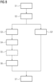
- Step S1 may include pre-manufacturing the at least two blade sections 8, 9.
- a mold 35 comprising a lower mold portion 36 and an upper mold portion 37 may be used for casting the at least two blade sections 8, 9.
- the mold 35 for example each of the upper and lower mold portions 36, 37 may include a protrusion 38, 39 at an inner mold surface 40, 41 for forming the respective outer recess 34, 42.
- the respective protrusion 38, 39 may be an integral part of the mold portion, as illustrated for the upper mold portion 37 (i.e. the mold portion 37 and the protrusion 39 are forming a one-piece element).
- the respective protrusion 38, 39 may be an add-on insert 43 attached to the mold portion, as illustrated with a dashed line for the lower mold portion 36.
- the at least two blade sections 8 and 9 are each made, for example, from a fiber-reinforced resin laminate.
- the at least two blade sections 8, 9 are, for example, manufactured by infusing a dry fiber lay-up (not shown) in the mold 35 with resin (not shown) by a vacuum infusion process.
- the blade sections 8, 9 may be pre-manufactured also in a different way.
- each of the at least two blade sections 8, 9 includes a respective spar web portion 15, 16 joined with its respective shell portion 11, 12.
- a second step S2 of the method the at least two blade section 8, 9 are aligned with each other, as shown in Fig. 5 .
- the at least one outer recess 34, 42 of the shell portion 11 of the inboard blade section 8 is aligned with the at least one outer recess 44 of the shell portion 12 of the outboard blade section 9.
- at least one overall outer recess 45 is formed.
- the at least one overall outer recess 45 has the predetermined total length L1 ( Fig. 5 ).
- the outer recesses 34, 42, 44 are, in particular, vacant.
- the at least two blade sections 8, 9 include the inboard blade section 8 comprising the root portion 27 and the outboard blade section 9 comprising a tip portion 59.
- the at least two blade sections 8, 9 are, for example, aligned with each other by using an alignment tool 46 ( Fig. 5 ).
- the alignment tool 46 comprises, for example, an outboard support structure 47 for positioning the outboard blade section 9 and an inboard support structure 48 for positioning the inboard blade section 8.
- the inboard support structure 48 may be configured for moving the inboard blade section 8 with respect to the (e.g., fixed) outboard blade section 9.
- the inboard support structure 46 may, for example, be configured to move the inboard blade section 8 in six degrees of freedom (X, Y, Z, Rot X , Rot Y , Rot Z ) with respect to the (e.g., fixed) outboard blade section 9.
- the direction X, Y, Z are perpendicular to each other.
- step S2 the at least two blade sections 8, 9 are, for example, aligned with each other by performing a global root to tip alignment from the root 27 to the tip 59 of the blade 3 ( Fig. 5 ).
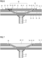
- a fiber lay-up 49 ( Fig. 6 ) is arranged in the overall outer recess 45 for forming one of the spar caps 18, 19 ( Fig. 2 ).
- the overall outer recess 45 at the suction side 30 of the blade 3 is shown.
- the illustrated fiber lay-up 49 is, hence, configured to become - in the manufactured state of the blade 3 - the spar cap 19 ( Fig. 2 ) at the suction side 30.
- a fiber lay-up similar as the fiber lay-up 49 is arranged in an overall recess provided at the pressure side 29 of the blade 3.
- step S3 the fiber lay-up for the entire spar cap 19 is arranged in the overall outer recess 45. Further, when arranged, the fiber lay-up 49 has the predetermined total length L1 ( Fig. 5 ).
- the fiber lay-up 49 may include a dry fiber lay-up 50, a semi-dry fiber lay-up 50' and/or a pre-impregnated fiber lay-up 50" ( Fig. 6 ).
- the fiber lay-up 49 may include a pre-casted fiber lay-up 51 such as a pre-casted reinforcement profile 26.
- the fiber lay-up 49 may include a core material 22.
- the fiber lay-up 49 may include carbon fibers which are lighter by volume than glass fibers and provide higher tensile strength and higher compressive strength than glass fibers.
- a carbon fiber reinforcement in the spar cap 18, 19 a reduced overall weight to length ratio and an increased blade stiffness may be achieved, which is of importance in particular for manufacturing very long blades.
- the fiber lay-up 49 may also include glass fibers.
- the fiber lay-up 49 arranged in the overall recess 45 includes the dry fiber lay-up 50, the semi-dry fiber lay-up 50' and/or the pre-impregnated fiber lay-up 50", the following steps S4 to S6 are carried out and/or at least step S6 is carried out. It is noted that the in the case that the fiber lay-up 49 arranged in the overall recess 45 includes the dry, semi-dry and/or pre-impregnated fiber lay-up 50, 50', 50", the fiber lay-up may in addition also include a pre-casted fiber lay-up 51.
- a fourth step S4 of the method the fiber lay-up 49 is covered with a vacuum bag 52 ( Fig. 6 ).
- the vacuum bag 52 is, for example, sealed with sealing elements 53 at an outer surface 28 of the shell 10.
- step S5 of the method the fiber lay-up 49 is infused with resin 54 ( Fig. 6 ) by vacuum-induced resin infusion.
- the fiber lay-up 49 includes the semi-dry and/or pre-impregnated fiber lay-up 50', 50" but no completely dry fiber lay-up 50, step S5 may be omitted.
- step S6 of the method the resin 54 infused in step S5 or a resin already contained in the semi-dry and/or pre-impregnated fiber lay-up 50', 50" is cured.
- heat is applied in the curing step.
- the overall outer recess 45 having the predetermined total length L1 is used as a mold 55 ( Figs. 5 and 6 ) in the resin infusion process (S5) and/or for curing the fiber lay-up 49 infused or pre-impregnated with resin 54.
- a continuous spar cap 18, 19 having the predetermined total length L1 is casted in one go.
- joining processes of spar cap sections and joining interfaces of a spar cap are avoided.
- step S3 may be carried out in a step S3'.
- an adhesive 56 ( Fig. 7 ) is applied in the overall outer recess 45 and/or on the pre-casted fiber lay-up 51' before arranging the fiber lay-up 49' including the pre-casted fiber lay-up 51' in the overall outer recess 45.
- steps S4 to S6 are omitted in this case.
- a seventh step S7 of the method the at least two blade sections 8, 9 are joined with each other.
- the shell portions 11, 12 of the at least two blade sections 8, 9 are joined with each other to form the shell joint 13 ( Fig. 2 ).
- This joining process is, for example, performed from within the inner cavity 33 ( Fig. 2 ) of the blade 3.
- step S7 also the shear web portions 15 and 16 ( Fig. 2 ) may be connected with each other.
- a further shear web portion (not shown) may be arranged in the gap 17 ( Fig. 2 ) and joined with the two shear web portions 15 and 16.
- a spar cap 18, 19 as a load-carrying beam.
- a leading-edge reinforcement beam 57 ( Fig. 2 ) and/or a trailing edge reinforcement beam 58 as a load-carrying beam may be manufactured by the described method.
- blades 3, 3' of a wind turbine 1 from several blade sections 8, 9 dividing the blade 3, 3' in its longitudinal direction A, larger blades can be manufactured.
- the at least two blade sections 8, 9 are pre-manufactured and the load-carrying beam, e.g., the spar cap 18, 19, is implemented in a subsequent production step only.
- having the overall outer recess 45 ( Fig. 5 ) spanning the entire length L1 of the load-carrying beam, e.g., the spar cap 18, 19 allows to manufacture the load-carrying beam as a continuous structural element without piecing it together.
- discontinuities in the material of the load-carrying beam can be avoided. Therefore, a higher structural integrity of the blade 3, 3' is achieved.
Landscapes
- Engineering & Computer Science (AREA)
- Mechanical Engineering (AREA)
- Wind Motors (AREA)
Priority Applications (2)
| Application Number | Priority Date | Filing Date | Title |
|---|---|---|---|
| EP21216387.7A EP4201660A1 (fr) | 2021-12-21 | 2021-12-21 | Procédé de fabrication d'une pale d'éolienne |
| PCT/EP2022/085530 WO2023117567A1 (fr) | 2021-12-21 | 2022-12-13 | Procédé de fabrication de pale d'éolienne |
Applications Claiming Priority (1)
| Application Number | Priority Date | Filing Date | Title |
|---|---|---|---|
| EP21216387.7A EP4201660A1 (fr) | 2021-12-21 | 2021-12-21 | Procédé de fabrication d'une pale d'éolienne |
Publications (1)
| Publication Number | Publication Date |
|---|---|
| EP4201660A1 true EP4201660A1 (fr) | 2023-06-28 |
Family
ID=78957793
Family Applications (1)
| Application Number | Title | Priority Date | Filing Date |
|---|---|---|---|
| EP21216387.7A Pending EP4201660A1 (fr) | 2021-12-21 | 2021-12-21 | Procédé de fabrication d'une pale d'éolienne |
Country Status (2)
| Country | Link |
|---|---|
| EP (1) | EP4201660A1 (fr) |
| WO (1) | WO2023117567A1 (fr) |
Citations (3)
| Publication number | Priority date | Publication date | Assignee | Title |
|---|---|---|---|---|
| WO2016189092A1 (fr) * | 2015-05-28 | 2016-12-01 | Blade Dynamics Limited | Pale de turbine éolienne et procédé d'assemblage de pale de turbine éolienne |
| EP3066338B1 (fr) * | 2013-11-05 | 2020-01-22 | Vestas Wind Systems A/S | Pale de rotor d'éolienne modulaire |
| EP3747639A1 (fr) | 2019-06-07 | 2020-12-09 | Siemens Gamesa Renewable Energy A/S | Procédé de fabrication d'une pale d'éolienne et pale d'éolienne |
-
2021
- 2021-12-21 EP EP21216387.7A patent/EP4201660A1/fr active Pending
-
2022
- 2022-12-13 WO PCT/EP2022/085530 patent/WO2023117567A1/fr unknown
Patent Citations (3)
| Publication number | Priority date | Publication date | Assignee | Title |
|---|---|---|---|---|
| EP3066338B1 (fr) * | 2013-11-05 | 2020-01-22 | Vestas Wind Systems A/S | Pale de rotor d'éolienne modulaire |
| WO2016189092A1 (fr) * | 2015-05-28 | 2016-12-01 | Blade Dynamics Limited | Pale de turbine éolienne et procédé d'assemblage de pale de turbine éolienne |
| EP3747639A1 (fr) | 2019-06-07 | 2020-12-09 | Siemens Gamesa Renewable Energy A/S | Procédé de fabrication d'une pale d'éolienne et pale d'éolienne |
Also Published As
| Publication number | Publication date |
|---|---|
| WO2023117567A1 (fr) | 2023-06-29 |
Similar Documents
| Publication | Publication Date | Title |
|---|---|---|
| CN110131095B (zh) | 叶片翼梁帽的非平面轮廓剖面的拉挤纤维复合材料条带 | |
| US11028824B2 (en) | Wind turbine blade with a trailing edge spacing section | |
| EP3727807B1 (fr) | Pale modulaire pour éolienne et procédé de fabrication associé | |
| EP2617555B1 (fr) | Pale de rotor d'éolienne dotée d'un bord de fuite comprenant des stratifils | |
| EP3953159B1 (fr) | Procédé de fabrication d'une pale d'éolienne et pale d'éolienne | |
| EP3066338B1 (fr) | Pale de rotor d'éolienne modulaire | |
| US20140271217A1 (en) | Efficient wind turbine blade design and associated manufacturing methods using rectangular spars and segmented shear web | |
| EP3867052B1 (fr) | Améliorations apportées à la fabrication de pales d'éolienne | |
| CN106574602B (zh) | 加强的风力涡轮机叶片部件 | |
| US11486350B2 (en) | Wind turbine blade with multiple spar caps | |
| EP4201660A1 (fr) | Procédé de fabrication d'une pale d'éolienne | |
| US20230025564A1 (en) | Method for manufacturing a wind turbine blade | |
| CN116234980A (zh) | 用于节段式风力涡轮机叶片的凸形翼梁桁杆 | |
| CN112955647A (zh) | 分段风力涡轮机叶片的制造 | |
| CN115485127A (zh) | 风力涡轮机叶片 | |
| US11994100B2 (en) | Manufacturing of segmented wind turbine blade | |
| EP4191052A1 (fr) | Pale d'éolienne et procédé de fabrication d'une pale d'éolienne | |
| EP4363711A1 (fr) | Pale d'éolienne |
Legal Events
| Date | Code | Title | Description |
|---|---|---|---|
| PUAI | Public reference made under article 153(3) epc to a published international application that has entered the european phase |
Free format text: ORIGINAL CODE: 0009012 |
|
| STAA | Information on the status of an ep patent application or granted ep patent |
Free format text: STATUS: THE APPLICATION HAS BEEN PUBLISHED |
|
| AK | Designated contracting states |
Kind code of ref document: A1 Designated state(s): AL AT BE BG CH CY CZ DE DK EE ES FI FR GB GR HR HU IE IS IT LI LT LU LV MC MK MT NL NO PL PT RO RS SE SI SK SM TR |
|
| STAA | Information on the status of an ep patent application or granted ep patent |
Free format text: STATUS: THE APPLICATION IS DEEMED TO BE WITHDRAWN |