EP4201546A1 - Preform can and method for producing same - Google Patents
Preform can and method for producing same Download PDFInfo
- Publication number
- EP4201546A1 EP4201546A1 EP21866322.7A EP21866322A EP4201546A1 EP 4201546 A1 EP4201546 A1 EP 4201546A1 EP 21866322 A EP21866322 A EP 21866322A EP 4201546 A1 EP4201546 A1 EP 4201546A1
- Authority
- EP
- European Patent Office
- Prior art keywords
- preform
- molded
- dome
- dome part
- axis
- Prior art date
- Legal status (The legal status is an assumption and is not a legal conclusion. Google has not performed a legal analysis and makes no representation as to the accuracy of the status listed.)
- Pending
Links
Images




Classifications
-
- B—PERFORMING OPERATIONS; TRANSPORTING
- B65—CONVEYING; PACKING; STORING; HANDLING THIN OR FILAMENTARY MATERIAL
- B65D—CONTAINERS FOR STORAGE OR TRANSPORT OF ARTICLES OR MATERIALS, e.g. BAGS, BARRELS, BOTTLES, BOXES, CANS, CARTONS, CRATES, DRUMS, JARS, TANKS, HOPPERS, FORWARDING CONTAINERS; ACCESSORIES, CLOSURES, OR FITTINGS THEREFOR; PACKAGING ELEMENTS; PACKAGES
- B65D17/00—Rigid or semi-rigid containers specially constructed to be opened by cutting or piercing, or by tearing of frangible members or portions
- B65D17/02—Rigid or semi-rigid containers specially constructed to be opened by cutting or piercing, or by tearing of frangible members or portions of curved cross-section, e.g. cans of circular or elliptical cross-section
-
- B—PERFORMING OPERATIONS; TRANSPORTING
- B21—MECHANICAL METAL-WORKING WITHOUT ESSENTIALLY REMOVING MATERIAL; PUNCHING METAL
- B21D—WORKING OR PROCESSING OF SHEET METAL OR METAL TUBES, RODS OR PROFILES WITHOUT ESSENTIALLY REMOVING MATERIAL; PUNCHING METAL
- B21D51/00—Making hollow objects
- B21D51/16—Making hollow objects characterised by the use of the objects
- B21D51/26—Making hollow objects characterised by the use of the objects cans or tins; Closing same in a permanent manner
- B21D51/2669—Transforming the shape of formed can bodies; Forming can bodies from flattened tubular blanks; Flattening can bodies
-
- B—PERFORMING OPERATIONS; TRANSPORTING
- B21—MECHANICAL METAL-WORKING WITHOUT ESSENTIALLY REMOVING MATERIAL; PUNCHING METAL
- B21D—WORKING OR PROCESSING OF SHEET METAL OR METAL TUBES, RODS OR PROFILES WITHOUT ESSENTIALLY REMOVING MATERIAL; PUNCHING METAL
- B21D22/00—Shaping without cutting, by stamping, spinning, or deep-drawing
- B21D22/20—Deep-drawing
- B21D22/30—Deep-drawing to finish articles formed by deep-drawing
-
- B—PERFORMING OPERATIONS; TRANSPORTING
- B21—MECHANICAL METAL-WORKING WITHOUT ESSENTIALLY REMOVING MATERIAL; PUNCHING METAL
- B21D—WORKING OR PROCESSING OF SHEET METAL OR METAL TUBES, RODS OR PROFILES WITHOUT ESSENTIALLY REMOVING MATERIAL; PUNCHING METAL
- B21D51/00—Making hollow objects
- B21D51/16—Making hollow objects characterised by the use of the objects
- B21D51/26—Making hollow objects characterised by the use of the objects cans or tins; Closing same in a permanent manner
-
- B—PERFORMING OPERATIONS; TRANSPORTING
- B65—CONVEYING; PACKING; STORING; HANDLING THIN OR FILAMENTARY MATERIAL
- B65D—CONTAINERS FOR STORAGE OR TRANSPORT OF ARTICLES OR MATERIALS, e.g. BAGS, BARRELS, BOTTLES, BOXES, CANS, CARTONS, CRATES, DRUMS, JARS, TANKS, HOPPERS, FORWARDING CONTAINERS; ACCESSORIES, CLOSURES, OR FITTINGS THEREFOR; PACKAGING ELEMENTS; PACKAGES
- B65D1/00—Rigid or semi-rigid containers having bodies formed in one piece, e.g. by casting metallic material, by moulding plastics, by blowing vitreous material, by throwing ceramic material, by moulding pulped fibrous material or by deep-drawing operations performed on sheet material
- B65D1/12—Cans, casks, barrels, or drums
- B65D1/14—Cans, casks, barrels, or drums characterised by shape
- B65D1/16—Cans, casks, barrels, or drums characterised by shape of curved cross-section, e.g. cylindrical
- B65D1/165—Cylindrical cans
-
- B—PERFORMING OPERATIONS; TRANSPORTING
- B21—MECHANICAL METAL-WORKING WITHOUT ESSENTIALLY REMOVING MATERIAL; PUNCHING METAL
- B21D—WORKING OR PROCESSING OF SHEET METAL OR METAL TUBES, RODS OR PROFILES WITHOUT ESSENTIALLY REMOVING MATERIAL; PUNCHING METAL
- B21D51/00—Making hollow objects
- B21D51/16—Making hollow objects characterised by the use of the objects
- B21D51/26—Making hollow objects characterised by the use of the objects cans or tins; Closing same in a permanent manner
- B21D51/2615—Edge treatment of cans or tins
- B21D51/263—Flanging
-
- B—PERFORMING OPERATIONS; TRANSPORTING
- B21—MECHANICAL METAL-WORKING WITHOUT ESSENTIALLY REMOVING MATERIAL; PUNCHING METAL
- B21D—WORKING OR PROCESSING OF SHEET METAL OR METAL TUBES, RODS OR PROFILES WITHOUT ESSENTIALLY REMOVING MATERIAL; PUNCHING METAL
- B21D51/00—Making hollow objects
- B21D51/16—Making hollow objects characterised by the use of the objects
- B21D51/26—Making hollow objects characterised by the use of the objects cans or tins; Closing same in a permanent manner
- B21D51/2615—Edge treatment of cans or tins
- B21D51/2638—Necking
Definitions
- the present invention relates to a preform of a can and a method of manufacturing the preform of the can.
- a two-piece can and a bottle can are known as a can body in which contents such as a drink and food can be contained. It is being promoted to thin the can body to reduce the weight of a can container, in order to cut down materials to be used. Even though the can container is thinned, the bottom shape of the can body is designed with various ideas to achieve a sufficient pressure resistance.
- a bottom shape of the can body having a dome part which is concave into the can body and an annular leg part provided around the dome part.
- Paten Literature 1 discloses: forming a first concave curved surface which is formed on an inner peripheral wall (inner peripheral section) continuous with a dome part of an annular convex part (leg part) and is curved and concave toward the outside of the radial direction orthogonal to a can axis in a vertical cross-sectional view taken along the can axis; in the dome part, forming a dome top located on the can axis, and a second concave curved surface which is connected to the outside of the dome top in the radial direction and is curved and concave with a radius of curvature smaller than that of the dome top; and forming a linear tapered section which is formed on an outer peripheral section of the dome part, connects between the first concave curved surface and the second concave curved surface, and contacts the first curved surface and the second curved surface.
- bottom reforming process is applied to the inner peripheral wall (inner peripheral section) of the annular convex part (leg part) to form the first concave curved surface and the tapered section, and the first concave curved surface is molded by using a roller.
- the first concave curved surface has a radius of curvature which is large enough to be subjected to the process with a roller. This limits to make the inner peripheral surface of the leg part more concave toward the outside of the radial direction orthogonal to the can axis.
- the present invention has been achieved considering the above-described circumstances to address the above-described problems. It is therefore an aspect of the object of the invention to improve the pressure resistance of a can body.
- a preform of a can includes: a dome part on a bottom of a bottomed cylindrical body, the dome part being concave into the bottomed cylindrical body; and an annular leg part projecting in a direction opposite to a direction in which the dome part is concave, the dome part and the annular part being molded to form the preform of the can, and an inner surface of the dome part being pressed to mold a molded can.
- a maximum height of the preform of the can from a ground plane to the dome part is greater than a maximum height of the molded can from a ground plane to the dome part.
- a length of an inner peripheral section of the leg part connecting between a ground point of the leg part and the dome part of the preform of the can is greater than a length of a curved end molded around the dome part of the molded can.
- the inner peripheral section of the leg part is inclined from the ground point of the leg part toward the can axis
- an inner peripheral section of the curved end connecting between a ground point of the curved end and the dome part of the molded can is inclined from the ground point of the curved end toward a direction opposite to the can axis.
- an approximately circular arc forming a tip section of the leg part and having a radius of curvature R1 is M R1
- a length of an approximately linear diameter reduction section of the inner peripheral section of the leg part is L
- a length of the curved end of the molded can is X
- X is smaller than M R1 plus L (X ⁇ M R1 +L).
- an angle of inclination between the ground plane of the preform of the can and the diameter reduction section of the inner peripheral section of the leg part is ⁇
- R1 is 0.8 mm to 2.2 mm
- L is 4.0 mm to 7.0 mm
- ⁇ is 70 degrees to 85 degrees.
- a method of manufacturing a preform of a can includes: providing a bottomed cylindrical body; and molding the preform of the can including: molding a dome part on a bottom of the bottomed cylindrical body, the dome part being concave into the bottomed cylindrical body; and molding an annular leg part projecting in a direction opposite to a direction in which the dome part is concave.
- a maximum height of the preform of the can from a ground plane to the dome part is greater than a maximum height of the molded can from a ground plane to the dome part; and in a vertical cross-sectional view taken along a can axis, a length of an inner peripheral section of the leg part connecting between a ground point of the leg part and the dome part of the preform of the can is greater than a length of a curved end molded around the dome part of the molded can.
- An inner surface of the dome part of the preform of the can is pressed to mold a molded can.
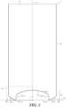
- Fig. 1 is a vertical cross-sectional view illustrating a preform of a can according to the present embodiment.
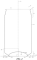
- Fig. 2 is a vertical cross-sectional view illustrating a can body molded from the preform of the can.
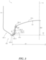
- Fig. 3 is an enlarged view illustrating region A1 of Fig. 1 .
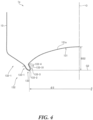
- Fig. 4 is an enlarged view illustrating region A2 of Fig. 2 .
- Fig. 5 is a flowchart illustrating a process of manufacturing the can body.
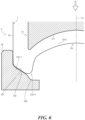
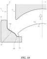
- Each of Fig. 6 to Fig. 10 is a partial cross-sectional view illustrating a molding device to mold a preform of a can.
- Fig. 11 is a partial cross-sectional view illustrating part of a leg part and a dome part before and after molding a curved end.
- Fig. 1 is a vertical cross-sectional view through which can axis O of a preform of a can 1 according to the embodiment passes.
- the preform of the can 1 is molded from a bottomed cylindrical body, and includes an opening 11, a cylindrical part 12, and a bottom 13.
- the cylindrical part 12 and the bottom 13 have the same shape across the entire circumference around the can axis O.
- the can axis O extends vertically to a ground plane G1 of the preform of the can 1.
- the bottom 13 includes a dome part 131 which is concave into the preform of the can 1, and an annular leg part 132 projecting in the direction opposite to the direction in which the dome part 131 is concave.
- the leg part 132 of the bottom 13 of the preform of the can 1 includes an outer wall 132-1 continuous with the cylindrical part 12, a ground point 132-2 contacting the ground plane G1, and an inner peripheral section 132-3 continuous with the dome part 131.
- Fig.2 is a vertical cross-sectional view through which the can axis O of a can body 1a molded from the preform of the can 1 passes. Also the can axis O of the can body 1a extends vertically to a ground plane G2.
- the can body 1a is a molded can molded by pressing an inner surface 131a of the dome part 131 and the outer wall 132-1 of the preform of the can 1 facing one another in the direction along the can axis O.
- the leg part 132 of the preform of the can 1 is partially deformed to mold a curved end 133. That is, the can body 1a illustrated in Fig. 2 includes the curved end 133 around the pressed dome part 131, which is molded from the leg part 132.
- the can body 1a includes a neck 14 having a diameter smaller than the outer diameter of the cylindrical part 12, and a flange 15 molded at the end (lip) of the neck 14 on the opening 11 side.
- the flange 15 is shaped to curl toward the outside of the can body 1a to hold and tighten a lid (not shown) thereafter.
- Fig. 3 is an enlarged view illustrating a region A1 including the cylindrical part 12, the dome part 131, and the leg part 132 of the preform of the can 1 illustrated in Fig. 1 .
- Fig. 4 is an enlarged view illustrating a region A2 including the cylindrical part 12, the dome part 131, and the leg part 132 with the curved end 133 of the can body 1a illustrated in Fig. 2 .
- Fig. 3 is a vertical cross-sectional view taken along the can axis O where the leg part 132 of the bottom 13 of the preform of the can 1 includes the outer wall 132-1 continuous with the cylindrical part 12 and the inner peripheral section 132-3 continuous with the dome part 131, which are continuous with one another at the ground point 132-2 contacting the ground plane G1.
- a tip section 132-4 of the leg part 132 is formed by part of the outer wall 132-1 and part of the inner peripheral section 132-3, and is shaped in an approximately circular arc including the ground point 132-2 and having a radius of curvature R1.
- a boundary section 132-6 is formed by part of the inner peripheral section 132-3 and part of the dome part 131, and is a shaped in an approximately circular arc including a boundary point 132-5 between the inner peripheral section 132-3 and the dome part 131 and having a radius of curvature R2.
- Fig. 4 is a vertical cross-sectional view taken along the can axis O where the leg part 132 of the bottom 13 of the can body 1a molded from the preform of the can 1 includes the curved end 133 formed between the outer wall 132-1 continuous with the cylindrical part 12 and the dome part 131.
- This curved end 133 includes an outer peripheral section 133-1 continuous with the outer wall 132-1 and an inner peripheral section 133-3 continuous with the dome part 131, which are continuous with one another at a ground point 133-2 contacting the ground plane G2.
- the inner peripheral section 133-3 and the dome part 131 are continuous with one another at a boundary point 133-4.
- the inner peripheral section 133-3 includes a tapered surface 133-31 which is an approximately straight line in the vertical cross-sectional view taken along the can axis O.
- the maximum height of the preform of the can 1 from the ground plane G1 to the dome part 131 is BS1 as illustrated in Fig. 3
- the maximum height of the can body 1a, which is a molded can, from the ground plane G2 to the dome part 131 is BS2 as illustrated in Fig. 4
- BS2 may be smaller than BS1 (BS2 ⁇ BS1 ⁇ (1)).
- a ground diameter which is a distance between two ground points 132-2 passing through the can axis O of the preform of the can 1 is ⁇ 1
- a ground diameter which is a distance between two ground points 133-2 passing through the can axis O of the molded can body 1a is ⁇ 2.
- ⁇ 2 may be smaller than ⁇ 1 ( ⁇ 2 ⁇ 1 ⁇ (2)).
- the preform of the can 1 may have BS1 of 13.75 mm, and ⁇ 1 of 49.0 mm, and in this case, the molded can body 1a may have BS2 of 11.20mm, and ⁇ 2 of 45.5 mm.
- the inner peripheral section 132-3 of the leg portion 132 is inclined from the ground point 132-2 of the leg part 132 toward the can axis O with respect to the direction parallel to the can axis O in the vertical cross-sectional view taken along the can axis O.
- the inner peripheral section 133-3 connecting between the ground point 133-2 of the curved end 133 of the molded can body 1a and the dome part 131 is inclined toward the direction opposite to the direction in which the inner peripheral section 132-3 of the leg part 132 is inclined toward the can axis O as illustrated in Fig. 3 , with respect to the direction parallel to the can axis O in the vertical cross-sectional view taken along the can axis O (that is, inclined from the ground point 133-2 toward the cylindrical part 12 with respect to the direction parallel to the can axis O).
- the inner peripheral section 132-3 of the leg 132 of the preform of the can 1 illustrated in Fig. 3 has an approximately linear diameter reduction section 132-31 having length L in the vertical cross-sectional view taken along the can axis O.
- the radius of curvature R1 is 0.8 mm to 2.2 mm
- the length L is 4.0 mm to 7.0 mm
- ⁇ is 70 degrees to 85 degrees ⁇ (3)).
- the radius of curvature R1 may be 1.7 mm
- the length L may be 5.9 mm
- the angle of inclination ⁇ may be 80 degrees
- the curved end 133 around the dome part 131 is molded at least from the inner peripheral section 132-3 of the leg part 132 of the preform of the can 1 illustrated in Fig. 3 .
- the inner peripheral section 132-3 of the leg part 132 connecting between the ground point 132-2 of the leg part 132 of the preform of the can 1 and the dome part 131 has length N in the vertical cross-sectional view taken along the can axis O illustrated in Fig. 3
- the curved end 133 molded around the dome part 131 of the can body 1a (molded can) has length X in the vertical cross-sectional view taken along the can axis o illustrated in Fig. 4
- X is smaller than N (X ⁇ N ⁇ (4)) because a desired shape of the curved end 133 is stably obtained in the bottom reforming process.
- the can body 1a is manufactured in the process with the following step S101 to step S108.
- step S101 of cupping a metal plate made of, for example, aluminum alloy is punched out into a circle, and drawing (cupping) is applied to the obtained circular metal plate with a cupping press to mold a cup-shaped body.
- Step S102 Molding a preform of a can>
- step S102 of molding a preform of a can subsequent to the step S101 drawing and ironing is applied to the cup-shaped body molded in the step S101; a bottomed cylindrical body including a cylindrical part and a bottom is molded; pressing is further applied to the bottom of the bottomed cylindrical body; and a dome part which is concave into the bottomed cylindrical body, and an annular leg part projecting in the direction opposite to the direction in which the dome part is concave are molded. Consequently, the preform of the can 1 is molded.
- a cleaning step to remove the lubricant may be added after the step S102.
- step S103 trimming to trim (cut) the lug of the opening end of the preform of the can 1 is performed by using a trimming device to even the height of the preform of the can 1 across the entire circumference.
- step S104 of painting and printing the outer surface subsequent to the step S103 the outer surface of at least the cylindrical part 12 and the bottom 13 of the preform of the can 1 is painted with a painting material for the outer surface to form a coating film, and then a design image is printed on the outer surface (outer peripheral surface) of the cylindrical part 12.
- this printed surface with the design image may be coated with varnish to form an overcoat layer, and then the overcoat layer may be dried and baked in an oven.
- step S105 of painting the inner surface subsequent to the step S104 the inner surface of the preform of the can 1 is painted with a painting material for the inner surface.
- This painting may be performed, for example, with a spray device.
- a painting material composition containing epoxy-acrylic copolymers and aqueous solvent may be given.
- the inner surface 131a of the preform of the can 1 is painted, and therefore it is possible to prevent the flavor of the content from reducing, and also to prevent corrosion of the metal.
- a drying step to dry the preform of the can 1 at a high temperature for example, about 190 degrees Celsius to 210 degrees Celsius may be added.
- step S106 of bottom reforming subsequent to the step S105 the preform of the can 1 is pressed such that the inner surface 131a of the dome part 131 of the preform of the can 1 painted in the step S105 and the outer wall 132-1 which face one another are pressed in the direction along the can axis O.
- the can body 1a molded can
- the molding device 2 includes a press object 21 configured to be inserted into the preform of the can 1 and contact the inner surface of the dome part 131, and a shaping die 22 to mold the curved end 133 by the pressing of the press object 21.
- the preform of the can 1 is placed on the shaping die 22 of the molding device 2 such that the outer wall 132-1 of the leg part 132 of the preform of the can 1 contacts a contact surface 221 of the shaping die 22 of the molding device 2 as illustrated in Fig. 6 .
- the press object 21 of the molding device 2 is moved toward the inner surface 131a of the dome part 131 (in the arrow direction along the can axis O), also as illustrated in Fig. 6 .
- the press object 21 continues to further move in the arrow direction along the can axis O as illustrated in Fig. 7 .
- the pressing surface 211 of the press object 21 contacts to press the inner surface 131a of the dome part 131.
- a pressing force from the contact surface 221 of the shaping die 22 is applied to the outer wall 132-1, and the tip section 132-4 of the leg part 132 of the preform of the can 1 is deformed from the contact surface 221 of the shaping die 22 to fit a curve shaping surface 222 as illustrated in Fig. 7 .
- the press object 21 continues to further press the inner surface 131a of the dome part 131 in the arrow direction as illustrated in Fig. 8 , and therefore an additional pressing force from the contact surface 221 of the shaping die 22 is applied to the outer wall 132-1.
- part of the leg part 132 of the preform of the can 1 is guided to the curve shaping surface 222, and therefore deformed to fit the curve shaping surface 222.
- the curved end 133 fitting the curve shaping surface 222 as illustrated in Fig. 9 is molded. By molding this curved end 133, the can body 1a as a molded can is obtained. After that, as illustrated in Fig.
- the press object 21 of the molding device 2 is moved in an arrow direction along the can axis O, which is opposite to the pressing direction, to space the press object 21 of the molding device 2 from the inner surface 131a of the dome part 131. Then, the can body 1a is removed from the molding device 2.
- the preform of the can 1 may be placed on the press object 21 of the molding device 2, and the shaping die 22 of the molding device 2 may be moved and spaced from the outer wall 132-1 of the leg part 132 of the preform of the can 1, and then the can body 1a may be removed from the molding device 2.
- the curved end 133 is molded by pressing the inner surface 131a of the dome part 131.
- a neck 14 is molded by applying die process (necking process) stepwise to the end of the cylindrical part 12 of the can body 1a on the opening 11 side by using a die process tool (necking die) (not shown).
- step S108 of flanging subsequent to the step S107 the end (lip) of the opening 11 is curled toward the outside of the can body 1a by using a roller (not shown) to mold the flange 15.
- the shape of the flange 15 is made to hold and fasten the lid thereafter.
- step S107 of necking and the step S108 of flanging may be performed before the step S106 of bottom reforming.
- the can body 1a is manufactured as a molded can.
- a drink is stored in the can body 1a as a content, and a step of holding and fastening to tightly seal the flange 15 and the lid (not shown) together is performed.
- a can container storing the drink, as a drink product, is manufactured.
- the inner surface of the leg part 132 of the preform of the can 1 before the curved end 133 is molded has the inclined surfaces such as the outer wall 132-1 and the approximately linear diameter reduction section 132-31 in the vertical cross-sectional view taken along the can axis O across the entire circumference.
- the approximately linear diameter reduction section 132-31 is inclined from the ground point 133-2 toward the opening of the can body 1a and the can axis O, rather than the inner surface of the inner peripheral wall of the annular convex part (leg part) of the can according to the conventional technology described in, for example, Patent Literature 1.
- the painting material sprayed by using a spray device in the painting work easily reaches the inner surface of the inner peripheral section 132-3, as well as the inner surface 131a of the dome part 131 and the inner surface of the outer wall 132-1.
- the bottom 13 of the preform of the can 1 it is possible to paint the inner surface of the leg part 132 without the waste of the painting material, and also to reduce the difference in the thickness of the coating film of the painting material for the inner surface to even the thickness.
- the inner surface and the outer surface of the preform of the can 1 are painted, and then, the preform of the can 1 is subjected to the bottom reforming by pressing the inner surface 131a of the dome part 131 as described above. Therefore, any load such as friction due to a roller is not applied like the conventional bottom reforming process by using the roller. Therefore, the process of manufacturing the can body 1a eliminates such a problem that the coating film on the inner surface and the outer surface of the leg part formed by previously painting the inner surface and the outer surface of the preform of the can 1a is prone to be peeled off.
- the aluminum oxide film is damaged by a load such as friction. This could generate rolling process marks (blacking) during sterilization by heating after the content is filled. As a result, the molded can body 1a could be disfigured.
- the process of manufacturing the can body 1a described above does not have this problem of disfiguring.
- the process of manufacturing the can body 1a is simple in such a way that the inner surface 131a of the dome part 131 of the preform of the can 1 and the outer wall 132-1 facing one another are pressed in the direction along the can axis O.
- it is possible to mold the curved end 133 which is a structure to improve the pressure resistance of the bottom 13 around the dome part 131.
- This process is far simpler than a way in which the curved end 133 is molded by the bottom reforming process with a roller from the outside of the inner peripheral section 132-3 of the leg part 132.
- this process is different from the conventional technology of the bottom reforming process with a roller in that friction between the leg part 132 and the shaping die 22 is small. Therefore, the painting material is not built up on the shaping die 22.
- dotted line E1 indicates part of the leg part 132 and the dome part 131 of the preform of the can 1 before the curved end 133 is molded
- solid line E2 indicates part of the leg part 132 and the dome part 131 of the can body 1a after the curved end 133 is molded
- dotted line G1 indicates the ground plane on which the preform of the can 1 is grounded at the ground point 132-2
- solid line G2 indicates the ground plane on which the molded can body 1a is grounded at the ground point 133-2.
- the inner peripheral section 132-3 of the leg part 132 of the preform of the can 1 is inclined from the ground point 132-2 of the leg part 132 toward the can axis O with respect to the direction parallel to the can axis O orthogonal to the ground plane G1.
- the above-described pressing is applied to the inner surface 131a of the dome part 131 of the preform of the can 1 to mold the curved end 133 as indicated by the solid line E2.
- the inner peripheral section 133-3 of the curved end 133 connecting between the ground point 133-2 of the curved end 133 and the dome part 131 is inclined toward the direction opposite to the direction in which the inner peripheral section 132-3 of the leg part 132 is inclined toward the can axis O, with respect to the direction parallel to the can axis O (that is, inclined from the ground point 133-2 toward the cylindrical part 12 with respect to the direction parallel to the can axis O).
- length N of the inner peripheral section 132-3 of the leg part 132 connecting between the ground point 132-2 of the leg part 132 and the dome part 131 of the preform of the can 1 is greater than length X of the curved end 133 molded around the dome part 131 of the can body 1a (molded can), as represented by the above-described expression (4).
- M R1 the length of an approximately circular arc forming tip section 132-4 of the leg part 132 on the dotted line E1 and having the radius of curvature R1
- X the length of the diameter reduction section 132-31 of the inner peripheral section 132-3 of the leg part 132 on the dotted line E1, which is an approximately linear in the vertical cross-sectional view taken along the can axis O
- M R1 the length of an approximately circular arc forming tip section 132-4 of the leg part 132 on the dotted line E1 and having the radius of curvature R1
- X is smaller than M R1 plus L (X ⁇ M R1 +L ⁇ (5)) because a desired shape of the curved end 133 can be stably provided in the bottom reforming process.
- M R1 may be 3.44 mm
- L may be 5.9 mm
- X may be 7.03 mm.
- the preform of the can 1 is molded with the numerical design that satisfies the above-described expressions (1) to (5).
- the inner peripheral section 133-3 of the curved end 133 is more concave toward the cylindrical part 12 than the conventional can body subjected to the bottom reforming process using a roller. Therefore, it is possible to achieve a sufficient pressure resistance of the bottom 13 of the can body 1a.
- the inner surface and the outer surface of the preform of the can 1 are painted, but this is by no means limiting. At least one of the inner surface and the outer surface of the preform of the can 1 may be painted. Also in this case, the bottom reforming is performed by pressing the inner surface 131a of the dome part 131 as described above. Therefore, the problem that the coating film is prone to be peeled off as described above does not occur.
- 1 preform of a can 11 opening, 12 cylindrical part,13 bottom, 14 neck, 12 flange,131 dome part, 131a inner surface, 132 leg part, 132-1 outer wall, 132-2 ground point,132-3 inner peripheral section,132-31 diameter reduction section132-4 tip part, 132-5 boundary point,132-6 boundary section,1a can body, 133 curved end,133-1 outer peripheral section, 133-2 ground point,133-3 inner peripheral section, 133-31 tapered surface,133-4 boundary point, 2 molding device,21 press object, 22 shaping die,211 pressing surface, 221 contact surface,222 curve shaping surface
Landscapes
- Engineering & Computer Science (AREA)
- Mechanical Engineering (AREA)
- Ceramic Engineering (AREA)
- Containers Having Bodies Formed In One Piece (AREA)
- Blow-Moulding Or Thermoforming Of Plastics Or The Like (AREA)
- Processing And Handling Of Plastics And Other Materials For Molding In General (AREA)
- Shaping Metal By Deep-Drawing, Or The Like (AREA)
- Filling Or Discharging Of Gas Storage Vessels (AREA)
Abstract
Description
- The present invention relates to a preform of a can and a method of manufacturing the preform of the can.
- A two-piece can and a bottle can are known as a can body in which contents such as a drink and food can be contained. It is being promoted to thin the can body to reduce the weight of a can container, in order to cut down materials to be used. Even though the can container is thinned, the bottom shape of the can body is designed with various ideas to achieve a sufficient pressure resistance.
- Generally, to increase the pressure resistance, there has been known a bottom shape of the can body having a dome part which is concave into the can body and an annular leg part provided around the dome part.
- In order to further enhance the pressure resistance, the shapes of the dome part and the leg part have been appropriately designed, respectively. For example, Paten Literature 1 discloses: forming a first concave curved surface which is formed on an inner peripheral wall (inner peripheral section) continuous with a dome part of an annular convex part (leg part) and is curved and concave toward the outside of the radial direction orthogonal to a can axis in a vertical cross-sectional view taken along the can axis; in the dome part, forming a dome top located on the can axis, and a second concave curved surface which is connected to the outside of the dome top in the radial direction and is curved and concave with a radius of curvature smaller than that of the dome top; and forming a linear tapered section which is formed on an outer peripheral section of the dome part, connects between the first concave curved surface and the second concave curved surface, and contacts the first curved surface and the second curved surface.
- PTL1:
Japanese Patent Application Laid-Open No. 2016-43991 - With the technology described in Patent Literature 1, bottom reforming process is applied to the inner peripheral wall (inner peripheral section) of the annular convex part (leg part) to form the first concave curved surface and the tapered section, and the first concave curved surface is molded by using a roller. With this bottom reforming process with a roller, the first concave curved surface has a radius of curvature which is large enough to be subjected to the process with a roller. This limits to make the inner peripheral surface of the leg part more concave toward the outside of the radial direction orthogonal to the can axis.
- In this way, it is difficult for the conventional bottom reforming process with a roller to reform the bottom into a desired shape, and consequently there is a problem of not being able to sufficiently improve the pressure resistance of the can body.
- The present invention has been achieved considering the above-described circumstances to address the above-described problems. It is therefore an aspect of the object of the invention to improve the pressure resistance of a can body.
- According to the invention, a preform of a can includes: a dome part on a bottom of a bottomed cylindrical body, the dome part being concave into the bottomed cylindrical body; and an annular leg part projecting in a direction opposite to a direction in which the dome part is concave, the dome part and the annular part being molded to form the preform of the can, and an inner surface of the dome part being pressed to mold a molded can. A maximum height of the preform of the can from a ground plane to the dome part is greater than a maximum height of the molded can from a ground plane to the dome part. In a vertical cross-sectional view taken along a can axis, a length of an inner peripheral section of the leg part connecting between a ground point of the leg part and the dome part of the preform of the can is greater than a length of a curved end molded around the dome part of the molded can.
- Preferably, in the vertical cross-sectional view taken along the can axis, the inner peripheral section of the leg part is inclined from the ground point of the leg part toward the can axis, and in the vertical cross-sectional view taken along the can axis, an inner peripheral section of the curved end connecting between a ground point of the curved end and the dome part of the molded can is inclined from the ground point of the curved end toward a direction opposite to the can axis.
- Preferably, in the vertical cross-sectional view taken along the can axis, provided that an approximately circular arc forming a tip section of the leg part and having a radius of curvature R1 is MR1, a length of an approximately linear diameter reduction section of the inner peripheral section of the leg part is L, and a length of the curved end of the molded can is X, X is smaller than MR1 plus L (X<MR1+L).
- Preferably, in the vertical cross-sectional view taken along the can axis, provided that an angle of inclination between the ground plane of the preform of the can and the diameter reduction section of the inner peripheral section of the leg part is θ, R1 is 0.8 mm to 2.2 mm, L is 4.0 mm to 7.0 mm, and θ is 70 degrees to 85 degrees.
- According to the invention, a method of manufacturing a preform of a can includes: providing a bottomed cylindrical body; and molding the preform of the can including: molding a dome part on a bottom of the bottomed cylindrical body, the dome part being concave into the bottomed cylindrical body; and molding an annular leg part projecting in a direction opposite to a direction in which the dome part is concave. In the molding:
a maximum height of the preform of the can from a ground plane to the dome part is greater than a maximum height of the molded can from a ground plane to the dome part; and in a vertical cross-sectional view taken along a can axis, a length of an inner peripheral section of the leg part connecting between a ground point of the leg part and the dome part of the preform of the can is greater than a length of a curved end molded around the dome part of the molded can. An inner surface of the dome part of the preform of the can is pressed to mold a molded can. - According to the invention, it is possible to improve the pressure resistance of a can body.
-
-
Fig. 1 is a vertical cross-sectional view illustrating a preform of a can according to an embodiment; -
Fig. 2 is a vertical cross-sectional view illustrating a can body molded from the preform of the can; -
Fig. 3 is an enlarged view illustrating region A1 ofFig. 1 ; -
Fig. 4 is an enlarged view illustrating region A2 ofFig. 2 ; -
Fig. 5 is a flowchart illustrating a process of manufacturing the can body; -
Fig. 6 is a partial cross-sectional view illustrating a molding device to mold a preform of a can; -
Fig. 7 is a partial cross-sectional view illustrating the molding device to mold the preform of the can; -
Fig. 8 is a partial cross-sectional view illustrating the molding device to mold the preform of the can; -
Fig. 9 is a partial cross-sectional view illustrating the molding device to mold the preform of the can; -
Fig. 10 is a partial cross-sectional view illustrating the molding device to mold the preform of the can; and -
Fig. 11 is a partial cross-sectional view illustrating part of a leg part and a dome part before and after molding a curved end. - Hereinafter, an embodiment of the invention (present embodiment) will be described with reference to the drawings.
Fig. 1 is a vertical cross-sectional view illustrating a preform of a can according to the present embodiment.Fig. 2 is a vertical cross-sectional view illustrating a can body molded from the preform of the can.Fig. 3 is an enlarged view illustrating region A1 ofFig. 1 .Fig. 4 is an enlarged view illustrating region A2 ofFig. 2 .Fig. 5 is a flowchart illustrating a process of manufacturing the can body. Each ofFig. 6 to Fig. 10 is a partial cross-sectional view illustrating a molding device to mold a preform of a can.Fig. 11 is a partial cross-sectional view illustrating part of a leg part and a dome part before and after molding a curved end. -
Fig. 1 is a vertical cross-sectional view through which can axis O of a preform of a can 1 according to the embodiment passes. The preform of the can 1 is molded from a bottomed cylindrical body, and includes anopening 11, acylindrical part 12, and abottom 13. Thecylindrical part 12 and thebottom 13 have the same shape across the entire circumference around the can axis O. The can axis O extends vertically to a ground plane G1 of the preform of the can 1. Thebottom 13 includes adome part 131 which is concave into the preform of the can 1, and anannular leg part 132 projecting in the direction opposite to the direction in which thedome part 131 is concave. Theleg part 132 of thebottom 13 of the preform of the can 1 includes an outer wall 132-1 continuous with thecylindrical part 12, a ground point 132-2 contacting the ground plane G1, and an inner peripheral section 132-3 continuous with thedome part 131. -
Fig.2 is a vertical cross-sectional view through which the can axis O of acan body 1a molded from the preform of the can 1 passes. Also the can axis O of thecan body 1a extends vertically to a ground plane G2. Thecan body 1a is a molded can molded by pressing aninner surface 131a of thedome part 131 and the outer wall 132-1 of the preform of the can 1 facing one another in the direction along the can axis O. By pressing theinner surface 131a of thedome part 131, theleg part 132 of the preform of the can 1 is partially deformed to mold acurved end 133. That is, thecan body 1a illustrated inFig. 2 includes thecurved end 133 around the presseddome part 131, which is molded from theleg part 132. - In addition, as illustrated in
Fig. 2 , thecan body 1a includes aneck 14 having a diameter smaller than the outer diameter of thecylindrical part 12, and aflange 15 molded at the end (lip) of theneck 14 on the opening 11 side. Theflange 15 is shaped to curl toward the outside of thecan body 1a to hold and tighten a lid (not shown) thereafter. -
Fig. 3 is an enlarged view illustrating a region A1 including thecylindrical part 12, thedome part 131, and theleg part 132 of the preform of the can 1 illustrated inFig. 1 . Meanwhile,Fig. 4 is an enlarged view illustrating a region A2 including thecylindrical part 12, thedome part 131, and theleg part 132 with thecurved end 133 of thecan body 1a illustrated inFig. 2 . -
Fig. 3 is a vertical cross-sectional view taken along the can axis O where theleg part 132 of the bottom 13 of the preform of the can 1 includes the outer wall 132-1 continuous with thecylindrical part 12 and the inner peripheral section 132-3 continuous with thedome part 131, which are continuous with one another at the ground point 132-2 contacting the ground plane G1. A tip section 132-4 of theleg part 132 is formed by part of the outer wall 132-1 and part of the inner peripheral section 132-3, and is shaped in an approximately circular arc including the ground point 132-2 and having a radius of curvature R1. Meanwhile, a boundary section 132-6 is formed by part of the inner peripheral section 132-3 and part of thedome part 131, and is a shaped in an approximately circular arc including a boundary point 132-5 between the inner peripheral section 132-3 and thedome part 131 and having a radius of curvature R2. -
Fig. 4 is a vertical cross-sectional view taken along the can axis O where theleg part 132 of the bottom 13 of thecan body 1a molded from the preform of the can 1 includes thecurved end 133 formed between the outer wall 132-1 continuous with thecylindrical part 12 and thedome part 131. Thiscurved end 133 includes an outer peripheral section 133-1 continuous with the outer wall 132-1 and an inner peripheral section 133-3 continuous with thedome part 131, which are continuous with one another at a ground point 133-2 contacting the ground plane G2. In addition, the inner peripheral section 133-3 and thedome part 131 are continuous with one another at a boundary point 133-4. Moreover, inFig. 4 , the inner peripheral section 133-3 includes a tapered surface 133-31 which is an approximately straight line in the vertical cross-sectional view taken along the can axis O. - The maximum height of the preform of the can 1 from the ground plane G1 to the
dome part 131 is BS1 as illustrated inFig. 3 , and the maximum height of thecan body 1a, which is a molded can, from the ground plane G2 to thedome part 131 is BS2 as illustrated inFig. 4 . Here, BS2 may be smaller than BS1 (BS2<BS1···(1)). - In addition, as illustrated in
Fig. 3 , a ground diameter which is a distance between two ground points 132-2 passing through the can axis O of the preform of the can 1 is ϕ1, and as illustrated inFig. 4 , a ground diameter which is a distance between two ground points 133-2 passing through the can axis O of the molded canbody 1a is ϕ2. Here, ϕ2 may be smaller than ϕ1 (ϕ2<ϕ1···(2)). - As a specific example, the preform of the can 1 may have BS1 of 13.75 mm, and ϕ1 of 49.0 mm, and in this case, the molded can
body 1a may have BS2 of 11.20mm, and ϕ2 of 45.5 mm. - In addition, as illustrated in
Fig. 3 , the inner peripheral section 132-3 of theleg portion 132 is inclined from the ground point 132-2 of theleg part 132 toward the can axis O with respect to the direction parallel to the can axis O in the vertical cross-sectional view taken along the can axis O. Meanwhile, as illustrated inFig. 4 , the inner peripheral section 133-3 connecting between the ground point 133-2 of thecurved end 133 of the molded canbody 1a and thedome part 131 is inclined toward the direction opposite to the direction in which the inner peripheral section 132-3 of theleg part 132 is inclined toward the can axis O as illustrated inFig. 3 , with respect to the direction parallel to the can axis O in the vertical cross-sectional view taken along the can axis O (that is, inclined from the ground point 133-2 toward thecylindrical part 12 with respect to the direction parallel to the can axis O). - The inner peripheral section 132-3 of the
leg 132 of the preform of the can 1 illustrated inFig. 3 has an approximately linear diameter reduction section 132-31 having length L in the vertical cross-sectional view taken along the can axis O. InFig. 3 , provided that an angle of inclination between the ground plane G1 of the preform of the can 1 (or a plane G1a parallel to the ground plane G) and the approximately linear diameter reduction section 132-31 toward the can axis O is θ, it is preferred that the radius of curvature R1 is 0.8 mm to 2.2 mm, the length L is 4.0 mm to 7.0 mm, and the angle of inclination θ is 70 degrees to 85 degrees (R1=0.8 mm to 2.2 mm, L=4.0 mm to 7.0 mm, θ is 70 degrees to 85 degrees ···(3)). As a specific example, the radius of curvature R1 may be 1.7 mm, the length L may be 5.9 mm, and the angle of inclination θ may be 80 degrees. - In the
can body 1a (molded can) illustrated inFig. 4 , thecurved end 133 around thedome part 131 is molded at least from the inner peripheral section 132-3 of theleg part 132 of the preform of the can 1 illustrated inFig. 3 . - Provided that the inner peripheral section 132-3 of the
leg part 132 connecting between the ground point 132-2 of theleg part 132 of the preform of the can 1 and thedome part 131 has length N in the vertical cross-sectional view taken along the can axis O illustrated inFig. 3 , and thecurved end 133 molded around thedome part 131 of thecan body 1a (molded can) has length X in the vertical cross-sectional view taken along the can axis o illustrated inFig. 4 , it is preferred that X is smaller than N (X<N···(4)) because a desired shape of thecurved end 133 is stably obtained in the bottom reforming process. - Next, a process of manufacturing the
can body 1a will be described using the flowchart illustrated inFig. 5 . Thecan body 1a is manufactured in the process with the following step S101 to step S108. - In step S101 of cupping, a metal plate made of, for example, aluminum alloy is punched out into a circle, and drawing (cupping) is applied to the obtained circular metal plate with a cupping press to mold a cup-shaped body.
- In step S102 of molding a preform of a can subsequent to the step S101, drawing and ironing is applied to the cup-shaped body molded in the step S101; a bottomed cylindrical body including a cylindrical part and a bottom is molded; pressing is further applied to the bottom of the bottomed cylindrical body; and a dome part which is concave into the bottomed cylindrical body, and an annular leg part projecting in the direction opposite to the direction in which the dome part is concave are molded. Consequently, the preform of the can 1 is molded. Here, when a lubricant and so forth is used in the step S101 and the step S102, a cleaning step to remove the lubricant may be added after the step S102.
- The preform of the can 1 molded in the step S102 has an uneven height because its opening end has a lug. Therefore, in step S103 subsequent to the step S102, trimming to trim (cut) the lug of the opening end of the preform of the can 1 is performed by using a trimming device to even the height of the preform of the can 1 across the entire circumference.
- In step S104 of painting and printing the outer surface subsequent to the step S103, the outer surface of at least the
cylindrical part 12 and the bottom 13 of the preform of the can 1 is painted with a painting material for the outer surface to form a coating film, and then a design image is printed on the outer surface (outer peripheral surface) of thecylindrical part 12. In addition, this printed surface with the design image may be coated with varnish to form an overcoat layer, and then the overcoat layer may be dried and baked in an oven. By this means, it is possible to finish the outer surface of the preform of the can 1 with improved smoothness and wearing resistance. - In step S105 of painting the inner surface subsequent to the step S104, the inner surface of the preform of the can 1 is painted with a painting material for the inner surface. This painting may be performed, for example, with a spray device.
- As an example of the painting material for the inner surface used herein, a painting material composition containing epoxy-acrylic copolymers and aqueous solvent may be given. In this way, the
inner surface 131a of the preform of the can 1 is painted, and therefore it is possible to prevent the flavor of the content from reducing, and also to prevent corrosion of the metal. Here, after the step S105 of painting the inner surface, a drying step to dry the preform of the can 1 at a high temperature, for example, about 190 degrees Celsius to 210 degrees Celsius may be added. - In step S106 of bottom reforming subsequent to the step S105, the preform of the can 1 is pressed such that the
inner surface 131a of thedome part 131 of the preform of the can 1 painted in the step S105 and the outer wall 132-1 which face one another are pressed in the direction along the can axis O. By this means, it is possible to mold thecan body 1a (molded can) including thecurved end 133 around thedome part 131. - In this bottom reforming, pressing is performed by using, for example, a
molding device 2 illustrated inFig. 6 . Themolding device 2 includes apress object 21 configured to be inserted into the preform of the can 1 and contact the inner surface of thedome part 131, and a shaping die 22 to mold thecurved end 133 by the pressing of thepress object 21. - First, the preform of the can 1 is placed on the shaping die 22 of the
molding device 2 such that the outer wall 132-1 of theleg part 132 of the preform of the can 1 contacts acontact surface 221 of the shaping die 22 of themolding device 2 as illustrated inFig. 6 . Next, thepress object 21 of themolding device 2 is moved toward theinner surface 131a of the dome part 131 (in the arrow direction along the can axis O), also as illustrated inFig. 6 . - Then, the
press object 21 continues to further move in the arrow direction along the can axis O as illustrated inFig. 7 . By this means, thepressing surface 211 of thepress object 21 contacts to press theinner surface 131a of thedome part 131. By the pressing as described above, a pressing force from thecontact surface 221 of the shaping die 22 is applied to the outer wall 132-1, and the tip section 132-4 of theleg part 132 of the preform of the can 1 is deformed from thecontact surface 221 of the shaping die 22 to fit acurve shaping surface 222 as illustrated inFig. 7 . - After that, as illustrated in
Fig. 8 , thepress object 21 continues to further press theinner surface 131a of thedome part 131 in the arrow direction as illustrated inFig. 8 , and therefore an additional pressing force from thecontact surface 221 of the shaping die 22 is applied to the outer wall 132-1. By this means, part of theleg part 132 of the preform of the can 1 is guided to thecurve shaping surface 222, and therefore deformed to fit thecurve shaping surface 222. Then, thecurved end 133 fitting thecurve shaping surface 222 as illustrated inFig. 9 is molded. By molding thiscurved end 133, thecan body 1a as a molded can is obtained. After that, as illustrated inFig. 10 , thepress object 21 of themolding device 2 is moved in an arrow direction along the can axis O, which is opposite to the pressing direction, to space thepress object 21 of themolding device 2 from theinner surface 131a of thedome part 131. Then, thecan body 1a is removed from themolding device 2. In contract, the preform of the can 1 may be placed on thepress object 21 of themolding device 2, and the shaping die 22 of themolding device 2 may be moved and spaced from the outer wall 132-1 of theleg part 132 of the preform of the can 1, and then thecan body 1a may be removed from themolding device 2. - As described above, in the step S106 of bottom reforming, the
curved end 133 is molded by pressing theinner surface 131a of thedome part 131. By this means, it is possible to incline the inner peripheral section 133-3 of thecurved end 133 from the ground point 132-2 toward thecylindrical part 12 with respect to the direction parallel to the can axis O. Therefore, it is possible to secure a sufficient length of the inner peripheral section 133-3. That is, the inner peripheral section 133-3 of thecurved end 133 can be more concave toward thecylindrical part 12 than the conventional bottom reforming process using a roller. Therefore, it is possible to achieve a sufficient pressure resistance of the bottom 13 of the molded canbody 1a. - In step S107 of necking subsequent to the step S106, a
neck 14 is molded by applying die process (necking process) stepwise to the end of thecylindrical part 12 of thecan body 1a on theopening 11 side by using a die process tool (necking die) (not shown). - In step S108 of flanging subsequent to the step S107, the end (lip) of the
opening 11 is curled toward the outside of thecan body 1a by using a roller (not shown) to mold theflange 15. The shape of theflange 15 is made to hold and fasten the lid thereafter. - Here, the step S107 of necking and the step S108 of flanging may be performed before the step S106 of bottom reforming.
- By the step S101 to the step S108 described above, the
can body 1a is manufactured as a molded can. Here, after the step S108, a drink is stored in thecan body 1a as a content, and a step of holding and fastening to tightly seal theflange 15 and the lid (not shown) together is performed. By this means, a can container storing the drink, as a drink product, is manufactured. - According to the process of manufacturing the
can body 1a, it is assured that the inner surface of theleg part 132 of the preform of the can 1 before thecurved end 133 is molded has the inclined surfaces such as the outer wall 132-1 and the approximately linear diameter reduction section 132-31 in the vertical cross-sectional view taken along the can axis O across the entire circumference. In particular, the approximately linear diameter reduction section 132-31 is inclined from the ground point 133-2 toward the opening of thecan body 1a and the can axis O, rather than the inner surface of the inner peripheral wall of the annular convex part (leg part) of the can according to the conventional technology described in, for example, Patent Literature 1. Therefore, the painting material sprayed by using a spray device in the painting work easily reaches the inner surface of the inner peripheral section 132-3, as well as theinner surface 131a of thedome part 131 and the inner surface of the outer wall 132-1. By this means, for the bottom 13 of the preform of the can 1, it is possible to paint the inner surface of theleg part 132 without the waste of the painting material, and also to reduce the difference in the thickness of the coating film of the painting material for the inner surface to even the thickness. The same applies to the painting of the outer surface of theleg part 132 of the preform of the can 1. - Moreover, according to the process of manufacturing the
can body 1a, the inner surface and the outer surface of the preform of the can 1 are painted, and then, the preform of the can 1 is subjected to the bottom reforming by pressing theinner surface 131a of thedome part 131 as described above. Therefore, any load such as friction due to a roller is not applied like the conventional bottom reforming process by using the roller. Therefore, the process of manufacturing thecan body 1a eliminates such a problem that the coating film on the inner surface and the outer surface of the leg part formed by previously painting the inner surface and the outer surface of the preform of thecan 1a is prone to be peeled off. - Meanwhile, if the conventional bottom reforming process with a roller is applied to the outer surface of the preform of the can 1 from the outside of the inner peripheral section 132-3 of the
leg part 132, the aluminum oxide film is damaged by a load such as friction. This could generate rolling process marks (blacking) during sterilization by heating after the content is filled. As a result, the molded canbody 1a could be disfigured. However, the process of manufacturing thecan body 1a described above does not have this problem of disfiguring. - Moreover, the process of manufacturing the
can body 1a is simple in such a way that theinner surface 131a of thedome part 131 of the preform of the can 1 and the outer wall 132-1 facing one another are pressed in the direction along the can axis O. By this means, it is possible to mold thecurved end 133 which is a structure to improve the pressure resistance of the bottom 13 around thedome part 131. This process is far simpler than a way in which thecurved end 133 is molded by the bottom reforming process with a roller from the outside of the inner peripheral section 132-3 of theleg part 132. Moreover, this process is different from the conventional technology of the bottom reforming process with a roller in that friction between theleg part 132 and the shaping die 22 is small. Therefore, the painting material is not built up on the shaping die 22. - Next, the length of the cross section of the
curved end 133 molded in theleg part 132 will be described with reference toFig. 11 . In the vertical cross-sectional view taken along the can axis O ofFig. 11 , dotted line E1 indicates part of theleg part 132 and thedome part 131 of the preform of the can 1 before thecurved end 133 is molded, and solid line E2 indicates part of theleg part 132 and thedome part 131 of thecan body 1a after thecurved end 133 is molded. In addition, inFig. 11 , dotted line G1 indicates the ground plane on which the preform of the can 1 is grounded at the ground point 132-2, and solid line G2 indicates the ground plane on which the molded canbody 1a is grounded at the ground point 133-2. - In the vertical cross-sectional view taken along the can axis O of
Fig. 11 , the inner peripheral section 132-3 of theleg part 132 of the preform of the can 1 is inclined from the ground point 132-2 of theleg part 132 toward the can axis O with respect to the direction parallel to the can axis O orthogonal to the ground plane G1. The above-described pressing is applied to theinner surface 131a of thedome part 131 of the preform of the can 1 to mold thecurved end 133 as indicated by the solid line E2. In thecan body 1a (molded can) after thecurved end 133 is molded, the inner peripheral section 133-3 of thecurved end 133 connecting between the ground point 133-2 of thecurved end 133 and thedome part 131 is inclined toward the direction opposite to the direction in which the inner peripheral section 132-3 of theleg part 132 is inclined toward the can axis O, with respect to the direction parallel to the can axis O (that is, inclined from the ground point 133-2 toward thecylindrical part 12 with respect to the direction parallel to the can axis O). - In the vertical cross-sectional view taken along the can axis O of
Fig. 11 , length N of the inner peripheral section 132-3 of theleg part 132 connecting between the ground point 132-2 of theleg part 132 and thedome part 131 of the preform of the can 1 is greater than length X of thecurved end 133 molded around thedome part 131 of thecan body 1a (molded can), as represented by the above-described expression (4). - Then, provided that the length of an approximately circular arc forming tip section 132-4 of the
leg part 132 on the dotted line E1 and having the radius of curvature R1 is MR1, and the length of the diameter reduction section 132-31 of the inner peripheral section 132-3 of theleg part 132 on the dotted line E1, which is an approximately linear in the vertical cross-sectional view taken along the can axis O is L, it is preferred that X is smaller than MR1 plus L (X<MR1+L···(5)) because a desired shape of thecurved end 133 can be stably provided in the bottom reforming process. As a specific example, for example, MR1 may be 3.44 mm, L may be 5.9 mm, and X may be 7.03 mm. - With the present embodiment, it is preferred that the preform of the can 1 is molded with the numerical design that satisfies the above-described expressions (1) to (5). By pressing the
inner surface 131a of thedome part 131 of the preform of the can 1 molded with this design, it is possible to mold thecan body 1a (molded can) including thecurved end 133 fitting thecurve shaping surface 222. - The inner peripheral section 133-3 of the
curved end 133 is more concave toward thecylindrical part 12 than the conventional can body subjected to the bottom reforming process using a roller. Therefore, it is possible to achieve a sufficient pressure resistance of the bottom 13 of thecan body 1a. - Here, with the above-described embodiment, the inner surface and the outer surface of the preform of the can 1 are painted, but this is by no means limiting. At least one of the inner surface and the outer surface of the preform of the can 1 may be painted. Also in this case, the bottom reforming is performed by pressing the
inner surface 131a of thedome part 131 as described above. Therefore, the problem that the coating film is prone to be peeled off as described above does not occur. - 1 preform of a can, 11 opening, 12 cylindrical part,13 bottom, 14 neck, 12 flange,131 dome part, 131a inner surface, 132 leg part, 132-1 outer wall, 132-2 ground point,132-3 inner peripheral section,132-31 diameter reduction section132-4 tip part, 132-5 boundary point,132-6 boundary section,1a can body, 133 curved end,133-1 outer peripheral section, 133-2 ground point,133-3 inner peripheral section, 133-31 tapered surface,133-4 boundary point, 2 molding device,21 press object, 22 shaping die,211 pressing surface, 221 contact surface,222 curve shaping surface
Claims (5)
- A preform of a can comprising:a dome part on a bottom of a bottomed cylindrical body, the dome part being concave into the bottomed cylindrical body; andan annular leg part projecting in a direction opposite to a direction in which the dome part is concave, the dome part and the annular part being molded to form the preform of the can, and an inner surface of the dome part being pressed to mold a molded can, wherein:a maximum height of the preform of the can from a ground plane to the dome part is greater than a maximum height of the molded can from a ground plane to the dome part; andin a vertical cross-sectional view taken along a can axis, a length of an inner peripheral section of the leg part connecting between a ground point of the leg part and the dome part of the preform of the can is greater than a length of a curved end molded around the dome part of the molded can.
- The preform of the can according to claim 1, wherein:in the vertical cross-sectional view taken along the can axis, the inner peripheral section of the leg part is inclined from the ground point of the leg part toward the can axis; andin the vertical cross-sectional view taken along the can axis, an inner peripheral section of the curved end connecting between a ground point of the curved end and the dome part of the molded can is inclined from the ground point of the curved end toward a direction opposite to the can axis.
- The preform of the can according to one of claims 1 and 2, wherein, in the vertical cross-sectional view taken along the can axis, provided that an approximately circular arc forming a tip section of the leg part and having a radius of curvature R1 is MR1, a length of an approximately linear diameter reduction section of the inner peripheral section of the leg part is L, and a length of the curved end of the molded can is X, X is smaller than MR1 plus L (X<MR1+L).
- The preform of the can according to claim 3, wherein, in the vertical cross-sectional view taken along the can axis, provided that an angle of inclination between the ground plane of the preform of the can and the diameter reduction section of the inner peripheral section of the leg part is θ, R1 is 0.8 mm to 2.2 mm, L is 4.0 mm to 7.0 mm, and θ is 70 degrees to 85 degrees.
- A method of manufacturing a preform of a can, comprising:providing a bottomed cylindrical body; andmolding the preform of the can including:molding a dome part on a bottom of the bottomed cylindrical body, the dome part being concave into the bottomed cylindrical body; andmolding an annular leg part projecting in a direction opposite to a direction in which the dome part is concave,wherein, in the molding:the preform of the can, an inner surface of the dome part of which is pressed to mold a molded can, is molded such that a maximum height of the preform of the can from a ground plane to the dome part is greater than a maximum height of the molded can from a ground plane to the dome part; andin a vertical cross-sectional view taken along a can axis, a length of an inner peripheral section of the leg part connecting between a ground point of the leg part and the dome part of the preform of the can is greater than a length of a curved end molded around the dome part of the molded can.
Applications Claiming Priority (2)
| Application Number | Priority Date | Filing Date | Title |
|---|---|---|---|
| JP2020152159A JP2022046225A (en) | 2020-09-10 | 2020-09-10 | Preform can, and manufacturing method thereof |
| PCT/JP2021/022873 WO2022054361A1 (en) | 2020-09-10 | 2021-06-16 | Preform can and method for producing same |
Publications (2)
| Publication Number | Publication Date |
|---|---|
| EP4201546A1 true EP4201546A1 (en) | 2023-06-28 |
| EP4201546A4 EP4201546A4 (en) | 2024-08-07 |
Family
ID=80631506
Family Applications (1)
| Application Number | Title | Priority Date | Filing Date |
|---|---|---|---|
| EP21866322.7A Pending EP4201546A4 (en) | 2020-09-10 | 2021-06-16 | PREFORM BOX AND ASSOCIATED PRODUCTION METHOD |
Country Status (6)
| Country | Link |
|---|---|
| US (1) | US12472550B2 (en) |
| EP (1) | EP4201546A4 (en) |
| JP (1) | JP2022046225A (en) |
| CN (1) | CN116133770B (en) |
| TW (1) | TWI784675B (en) |
| WO (1) | WO2022054361A1 (en) |
Families Citing this family (1)
| Publication number | Priority date | Publication date | Assignee | Title |
|---|---|---|---|---|
| JP2022046225A (en) | 2020-09-10 | 2022-03-23 | 東洋製罐株式会社 | Preform can, and manufacturing method thereof |
Family Cites Families (41)
| Publication number | Priority date | Publication date | Assignee | Title |
|---|---|---|---|---|
| US3693828A (en) * | 1970-07-22 | 1972-09-26 | Crown Cork & Seal Co | Seamless steel containers |
| US3811393A (en) * | 1973-01-12 | 1974-05-21 | Stolle Corp | Manufacture of cans and the like |
| US4515284A (en) * | 1980-08-21 | 1985-05-07 | Reynolds Metals Company | Can body bottom configuration |
| GB2114031B (en) * | 1982-02-02 | 1985-10-09 | Metal Box Plc | Method of forming containers |
| US4685582A (en) * | 1985-05-20 | 1987-08-11 | National Can Corporation | Container profile with stacking feature |
| US4834256A (en) * | 1987-07-31 | 1989-05-30 | Pac International, Inc. | Can with domed bottom structure |
| JP2647485B2 (en) * | 1988-04-06 | 1997-08-27 | 三菱重工業株式会社 | Bottom structure of thin can |
| US5836473A (en) * | 1990-04-06 | 1998-11-17 | Ball Corporation | Beverage container with increased bottom strength |
| JPH04123825A (en) * | 1990-09-11 | 1992-04-23 | Kobe Steel Ltd | Manufacture of di can body of high pressure withstanding strength and can body |
| US5105973B1 (en) * | 1990-10-22 | 1998-06-02 | Ball Corp | Beverage container with improved bottom strength |
| GB9216247D0 (en) * | 1992-07-30 | 1992-09-09 | Cmb Foodcan Plc | Souffle:can ends |
| US5355709A (en) * | 1992-11-10 | 1994-10-18 | Crown Cork & Seal Company | Methods and apparatus for expansion reforming the bottom profile of a drawn and ironed container |
| US5605069A (en) * | 1995-04-12 | 1997-02-25 | Ball Corporation | Beverage container with wavy transition wall geometry and method for producing the same |
| US5730314A (en) * | 1995-05-26 | 1998-03-24 | Anheuser-Busch Incorporated | Controlled growth can with two configurations |
| JPH09285832A (en) * | 1996-04-23 | 1997-11-04 | Kishimoto Akira | Seamless can and its molding method |
| NL1008468C2 (en) * | 1998-03-04 | 1999-09-07 | Hoogovens Staal Bv | Method for the manufacture of a can by wall stretches. |
| US5934127A (en) * | 1998-05-12 | 1999-08-10 | Ihly Industries, Inc. | Method and apparatus for reforming a container bottom |
| EP1127795B1 (en) * | 1998-06-03 | 2004-08-11 | Crown Cork & Seal Technologies Corporation | Can bottom having improved pressure resistance and apparatus for making same |
| US6434996B1 (en) * | 1998-06-11 | 2002-08-20 | Crown Cork & Seal Technologies Corporation | Punch assembly for forming a base in a metal beverage can |
| US6182852B1 (en) * | 1999-08-25 | 2001-02-06 | Metal Container Corporation | Container and method of manufacture |
| JP2002035875A (en) * | 2000-07-14 | 2002-02-05 | Mitsubishi Materials Corp | Can manufacturing method and manufacturing apparatus |
| US20040035871A1 (en) * | 2002-08-20 | 2004-02-26 | Thomas Chupak | Aluminum aerosol can and aluminum bottle and method of manufacture |
| US7398894B2 (en) * | 2003-11-24 | 2008-07-15 | Metal Container Corporation | Container bottom, method of manufacture, and method of testing |
| US8162170B1 (en) * | 2005-04-19 | 2012-04-24 | Massad Gary L | Tip resistant beverage container providing a tip lip |
| JP4692147B2 (en) * | 2005-08-12 | 2011-06-01 | Jfeスチール株式会社 | Two-piece can manufacturing method and two-piece laminated can |
| DK1882535T3 (en) * | 2006-07-26 | 2010-08-30 | Impress Group Bv | Method and apparatus for forming a steel pressure vessel, pressure vessel and a preliminary form thereof |
| US8141406B2 (en) * | 2008-10-09 | 2012-03-27 | Container Development, Ltd. | Method and apparatus for forming a can shell |
| US9327338B2 (en) * | 2012-12-20 | 2016-05-03 | Alcoa Inc. | Knockout for use while necking a metal container, die system for necking a metal container and method of necking a metal container |
| GB201306765D0 (en) * | 2013-04-12 | 2013-05-29 | Crown Packaging Technology Inc | Method and apparatus for manufacturing a can end |
| US20160318645A1 (en) * | 2013-12-16 | 2016-11-03 | Ball Europe Gmbh | Can body |
| JP6713741B2 (en) | 2014-08-20 | 2020-06-24 | ユニバーサル製缶株式会社 | can |
| FR3030341B1 (en) * | 2014-12-17 | 2017-06-23 | Sidel Participations | CONTAINER WITH LARGE SLEEVE WITH RETAINED SLEEVE |
| PL3647217T3 (en) * | 2016-02-29 | 2022-11-28 | Crown Packaging Technology, Inc. | Concave can end |
| EP3523065B1 (en) * | 2016-10-06 | 2026-05-06 | Stolle Machinery Company, LLC | Tooling for selectively forming a blank of material into a container |
| JP6820728B2 (en) * | 2016-11-29 | 2021-01-27 | ユニバーサル製缶株式会社 | Bottle cans and their manufacturing methods |
| US20180178947A1 (en) * | 2016-12-28 | 2018-06-28 | Donald Julius | Beverage Container |
| JP7238254B2 (en) * | 2017-10-30 | 2023-03-14 | 東洋製罐株式会社 | can container |
| CN118768448A (en) * | 2019-01-30 | 2024-10-15 | 东洋制罐集团控股株式会社 | Seamless tank body and method for manufacturing seamless tank body |
| EP3939901B1 (en) * | 2019-03-14 | 2026-02-18 | Toyo Seikan Co., Ltd. | Seamless can, and resin-coated metal plate for molding seamless can |
| EP4122620B1 (en) * | 2020-03-18 | 2025-08-06 | Toyo Seikan Co., Ltd. | Can container and method for producing same |
| JP2022046225A (en) | 2020-09-10 | 2022-03-23 | 東洋製罐株式会社 | Preform can, and manufacturing method thereof |
-
2020
- 2020-09-10 JP JP2020152159A patent/JP2022046225A/en active Pending
-
2021
- 2021-06-16 WO PCT/JP2021/022873 patent/WO2022054361A1/en not_active Ceased
- 2021-06-16 CN CN202180061923.6A patent/CN116133770B/en active Active
- 2021-06-16 EP EP21866322.7A patent/EP4201546A4/en active Pending
- 2021-08-18 TW TW110130532A patent/TWI784675B/en active
-
2023
- 2023-02-28 US US18/115,025 patent/US12472550B2/en active Active
Also Published As
| Publication number | Publication date |
|---|---|
| TWI784675B (en) | 2022-11-21 |
| EP4201546A4 (en) | 2024-08-07 |
| JP2022046225A (en) | 2022-03-23 |
| CN116133770A (en) | 2023-05-16 |
| CN116133770B (en) | 2025-11-25 |
| US12472550B2 (en) | 2025-11-18 |
| TW202214491A (en) | 2022-04-16 |
| US20230201908A1 (en) | 2023-06-29 |
| WO2022054361A1 (en) | 2022-03-17 |
Similar Documents
| Publication | Publication Date | Title |
|---|---|---|
| US8016148B2 (en) | Necked-in can body and method for making same | |
| JP7259892B2 (en) | Can body manufacturing method | |
| EP0260084A2 (en) | Metal container and method of manufacturing the same | |
| JP7027229B2 (en) | Bottle-shaped cans with caps and their manufacturing equipment | |
| US20230219127A1 (en) | Method of manufacturing can body and manufacturing line of the same | |
| US12472550B2 (en) | Preform of a can and method of manufacturing the same | |
| JP2005335726A (en) | Manufacturing method for bottle-shaped cans | |
| JP2001315745A (en) | Container for filling liquid material and method for producing the same | |
| JP2002292434A (en) | Manufacturing method of metal sheet container parts and metal sheet container parts | |
| US20250256317A1 (en) | Method for manufacturing seamless can | |
| JP4229650B2 (en) | Bottle-shaped cans | |
| JP2004168346A (en) | Method of manufacturing can body with printed pattern up to shoulder | |
| JP2018184188A (en) | Bottle can and bottle can with cap | |
| JP7033857B2 (en) | Bottle cans and bottle cans with caps | |
| JP2021020702A (en) | Bottle can and manufacturing method of the same | |
| JP6735651B2 (en) | Bottle can manufacturing method | |
| JPH0327934Y2 (en) | ||
| JPS61176433A (en) | Manufacture of deformed can | |
| JP2020040712A (en) | Bottle can and method for manufacturing same | |
| JP2026032683A (en) | Can body manufacturing method | |
| JP7357430B2 (en) | Bottle cans and bottle cans with caps | |
| JPH0371938A (en) | Manufacture of seamless can | |
| JP2023070419A (en) | Resin-coated aluminum alloy drawing and ironing can | |
| JP2001335018A (en) | Can body reinforcement structure | |
| JP2020152445A (en) | Bottle cans and their manufacturing methods |
Legal Events
| Date | Code | Title | Description |
|---|---|---|---|
| STAA | Information on the status of an ep patent application or granted ep patent |
Free format text: STATUS: THE INTERNATIONAL PUBLICATION HAS BEEN MADE |
|
| PUAI | Public reference made under article 153(3) epc to a published international application that has entered the european phase |
Free format text: ORIGINAL CODE: 0009012 |
|
| STAA | Information on the status of an ep patent application or granted ep patent |
Free format text: STATUS: REQUEST FOR EXAMINATION WAS MADE |
|
| 17P | Request for examination filed |
Effective date: 20230322 |
|
| AK | Designated contracting states |
Kind code of ref document: A1 Designated state(s): AL AT BE BG CH CY CZ DE DK EE ES FI FR GB GR HR HU IE IS IT LI LT LU LV MC MK MT NL NO PL PT RO RS SE SI SK SM TR |
|
| DAV | Request for validation of the european patent (deleted) | ||
| DAX | Request for extension of the european patent (deleted) | ||
| A4 | Supplementary search report drawn up and despatched |
Effective date: 20240708 |
|
| RIC1 | Information provided on ipc code assigned before grant |
Ipc: B65D 1/46 20060101ALI20240702BHEP Ipc: B65D 1/16 20060101ALI20240702BHEP Ipc: B21D 51/26 20060101ALI20240702BHEP Ipc: B21D 22/30 20060101ALI20240702BHEP Ipc: B21D 22/28 20060101AFI20240702BHEP |