EP4201519A1 - Catalyseur sous enveloppe destiné à la production d'esters carboniques d'alcényle à distribution améliorée de pd et d'au - Google Patents
Catalyseur sous enveloppe destiné à la production d'esters carboniques d'alcényle à distribution améliorée de pd et d'au Download PDFInfo
- Publication number
- EP4201519A1 EP4201519A1 EP21216647.4A EP21216647A EP4201519A1 EP 4201519 A1 EP4201519 A1 EP 4201519A1 EP 21216647 A EP21216647 A EP 21216647A EP 4201519 A1 EP4201519 A1 EP 4201519A1
- Authority
- EP
- European Patent Office
- Prior art keywords
- catalyst
- range
- temperature
- concentration
- maximum
- Prior art date
- Legal status (The legal status is an assumption and is not a legal conclusion. Google has not performed a legal analysis and makes no representation as to the accuracy of the status listed.)
- Pending
Links
- 239000003054 catalyst Substances 0.000 title claims abstract description 215
- -1 alkenyl carboxylic acid esters Chemical class 0.000 title claims description 11
- 238000009826 distribution Methods 0.000 title abstract description 22
- 238000000034 method Methods 0.000 claims abstract description 59
- 229910052737 gold Inorganic materials 0.000 claims abstract description 33
- 229910052763 palladium Inorganic materials 0.000 claims abstract description 30
- 238000004519 manufacturing process Methods 0.000 claims abstract description 13
- KDLHZDBZIXYQEI-UHFFFAOYSA-N palladium Substances [Pd] KDLHZDBZIXYQEI-UHFFFAOYSA-N 0.000 claims description 115
- 239000010931 gold Substances 0.000 claims description 101
- 150000001875 compounds Chemical class 0.000 claims description 63
- 239000002243 precursor Substances 0.000 claims description 53
- XLYOFNOQVPJJNP-UHFFFAOYSA-N water Substances O XLYOFNOQVPJJNP-UHFFFAOYSA-N 0.000 claims description 30
- SCVFZCLFOSHCOH-UHFFFAOYSA-M potassium acetate Chemical compound [K+].CC([O-])=O SCVFZCLFOSHCOH-UHFFFAOYSA-M 0.000 claims description 22
- 238000001035 drying Methods 0.000 claims description 18
- 229910052751 metal Inorganic materials 0.000 claims description 14
- 239000002184 metal Substances 0.000 claims description 14
- PCHJSUWPFVWCPO-UHFFFAOYSA-N gold Chemical compound [Au] PCHJSUWPFVWCPO-UHFFFAOYSA-N 0.000 claims description 10
- 238000005507 spraying Methods 0.000 claims description 9
- 229910052783 alkali metal Inorganic materials 0.000 claims description 8
- 235000011056 potassium acetate Nutrition 0.000 claims description 8
- 238000013019 agitation Methods 0.000 claims description 7
- 150000002739 metals Chemical class 0.000 claims description 5
- 238000011282 treatment Methods 0.000 claims description 5
- 239000012298 atmosphere Substances 0.000 claims description 4
- 230000001590 oxidative effect Effects 0.000 claims description 3
- HVAMZGADVCBITI-UHFFFAOYSA-M pent-4-enoate Chemical compound [O-]C(=O)CCC=C HVAMZGADVCBITI-UHFFFAOYSA-M 0.000 claims description 3
- 239000000178 monomer Substances 0.000 claims description 2
- XTXRWKRVRITETP-UHFFFAOYSA-N Vinyl acetate Chemical group CC(=O)OC=C XTXRWKRVRITETP-UHFFFAOYSA-N 0.000 abstract description 14
- 239000000243 solution Substances 0.000 description 47
- QTBSBXVTEAMEQO-UHFFFAOYSA-N Acetic acid Chemical compound CC(O)=O QTBSBXVTEAMEQO-UHFFFAOYSA-N 0.000 description 26
- HEMHJVSKTPXQMS-UHFFFAOYSA-M sodium hydroxide Inorganic materials [OH-].[Na+] HEMHJVSKTPXQMS-UHFFFAOYSA-M 0.000 description 24
- IJGRMHOSHXDMSA-UHFFFAOYSA-N Atomic nitrogen Chemical compound N#N IJGRMHOSHXDMSA-UHFFFAOYSA-N 0.000 description 19
- 235000012216 bentonite Nutrition 0.000 description 19
- 238000005259 measurement Methods 0.000 description 18
- 239000000203 mixture Substances 0.000 description 18
- 239000011248 coating agent Substances 0.000 description 17
- 238000000576 coating method Methods 0.000 description 17
- 239000000440 bentonite Substances 0.000 description 15
- 229910000278 bentonite Inorganic materials 0.000 description 15
- SVPXDRXYRYOSEX-UHFFFAOYSA-N bentoquatam Chemical compound O.O=[Si]=O.O=[Al]O[Al]=O SVPXDRXYRYOSEX-UHFFFAOYSA-N 0.000 description 15
- 229910000510 noble metal Inorganic materials 0.000 description 15
- 239000007789 gas Substances 0.000 description 13
- KWYUFKZDYYNOTN-UHFFFAOYSA-M Potassium hydroxide Chemical compound [OH-].[K+] KWYUFKZDYYNOTN-UHFFFAOYSA-M 0.000 description 12
- 239000008367 deionised water Substances 0.000 description 12
- 229910021641 deionized water Inorganic materials 0.000 description 12
- 239000011148 porous material Substances 0.000 description 12
- 239000000523 sample Substances 0.000 description 11
- 239000007921 spray Substances 0.000 description 11
- 229910052760 oxygen Inorganic materials 0.000 description 10
- QTBSBXVTEAMEQO-UHFFFAOYSA-M Acetate Chemical compound CC([O-])=O QTBSBXVTEAMEQO-UHFFFAOYSA-M 0.000 description 9
- 239000002253 acid Substances 0.000 description 9
- 229910052757 nitrogen Inorganic materials 0.000 description 9
- 239000001301 oxygen Substances 0.000 description 9
- 229910052615 phyllosilicate Inorganic materials 0.000 description 9
- VGGSQFUCUMXWEO-UHFFFAOYSA-N Ethene Chemical compound C=C VGGSQFUCUMXWEO-UHFFFAOYSA-N 0.000 description 8
- QVGXLLKOCUKJST-UHFFFAOYSA-N atomic oxygen Chemical compound [O] QVGXLLKOCUKJST-UHFFFAOYSA-N 0.000 description 8
- 238000006243 chemical reaction Methods 0.000 description 8
- 239000011261 inert gas Substances 0.000 description 8
- 239000005977 Ethylene Substances 0.000 description 7
- BPQQTUXANYXVAA-UHFFFAOYSA-N Orthosilicate Chemical compound [O-][Si]([O-])([O-])[O-] BPQQTUXANYXVAA-UHFFFAOYSA-N 0.000 description 7
- 229910052792 caesium Inorganic materials 0.000 description 7
- TVFDJXOCXUVLDH-UHFFFAOYSA-N caesium atom Chemical compound [Cs] TVFDJXOCXUVLDH-UHFFFAOYSA-N 0.000 description 7
- 230000000694 effects Effects 0.000 description 7
- 229910052739 hydrogen Inorganic materials 0.000 description 7
- XKRFYHLGVUSROY-UHFFFAOYSA-N Argon Chemical compound [Ar] XKRFYHLGVUSROY-UHFFFAOYSA-N 0.000 description 6
- CURLTUGMZLYLDI-UHFFFAOYSA-N Carbon dioxide Chemical compound O=C=O CURLTUGMZLYLDI-UHFFFAOYSA-N 0.000 description 6
- 230000003068 static effect Effects 0.000 description 6
- 239000002585 base Substances 0.000 description 5
- 229910052799 carbon Inorganic materials 0.000 description 5
- 150000003112 potassium compounds Chemical class 0.000 description 5
- 239000011734 sodium Substances 0.000 description 5
- 230000005461 Bremsstrahlung Effects 0.000 description 4
- UFHFLCQGNIYNRP-UHFFFAOYSA-N Hydrogen Chemical compound [H][H] UFHFLCQGNIYNRP-UHFFFAOYSA-N 0.000 description 4
- 239000007864 aqueous solution Substances 0.000 description 4
- 239000000969 carrier Substances 0.000 description 4
- 230000003197 catalytic effect Effects 0.000 description 4
- 239000003638 chemical reducing agent Substances 0.000 description 4
- 238000009792 diffusion process Methods 0.000 description 4
- 238000001704 evaporation Methods 0.000 description 4
- 230000008020 evaporation Effects 0.000 description 4
- 238000011049 filling Methods 0.000 description 4
- 239000012530 fluid Substances 0.000 description 4
- 239000001257 hydrogen Substances 0.000 description 4
- 238000005470 impregnation Methods 0.000 description 4
- 238000011068 loading method Methods 0.000 description 4
- 239000000463 material Substances 0.000 description 4
- VNWKTOKETHGBQD-UHFFFAOYSA-N methane Chemical compound C VNWKTOKETHGBQD-UHFFFAOYSA-N 0.000 description 4
- NXJCBFBQEVOTOW-UHFFFAOYSA-L palladium(2+);dihydroxide Chemical compound O[Pd]O NXJCBFBQEVOTOW-UHFFFAOYSA-L 0.000 description 4
- 239000010970 precious metal Substances 0.000 description 4
- VEXZGXHMUGYJMC-UHFFFAOYSA-M Chloride anion Chemical compound [Cl-] VEXZGXHMUGYJMC-UHFFFAOYSA-M 0.000 description 3
- OKKJLVBELUTLKV-UHFFFAOYSA-N Methanol Chemical compound OC OKKJLVBELUTLKV-UHFFFAOYSA-N 0.000 description 3
- MUBZPKHOEPUJKR-UHFFFAOYSA-N Oxalic acid Chemical compound OC(=O)C(O)=O MUBZPKHOEPUJKR-UHFFFAOYSA-N 0.000 description 3
- 239000012696 Pd precursors Substances 0.000 description 3
- 238000010306 acid treatment Methods 0.000 description 3
- 150000001340 alkali metals Chemical class 0.000 description 3
- 229910052782 aluminium Inorganic materials 0.000 description 3
- 229910052786 argon Inorganic materials 0.000 description 3
- 238000001354 calcination Methods 0.000 description 3
- 239000001569 carbon dioxide Substances 0.000 description 3
- 229910002092 carbon dioxide Inorganic materials 0.000 description 3
- 239000012876 carrier material Substances 0.000 description 3
- 238000000921 elemental analysis Methods 0.000 description 3
- 238000010438 heat treatment Methods 0.000 description 3
- 150000002736 metal compounds Chemical class 0.000 description 3
- 238000002459 porosimetry Methods 0.000 description 3
- 239000002244 precipitate Substances 0.000 description 3
- 150000003839 salts Chemical class 0.000 description 3
- 238000001179 sorption measurement Methods 0.000 description 3
- BDAGIHXWWSANSR-UHFFFAOYSA-M Formate Chemical compound [O-]C=O BDAGIHXWWSANSR-UHFFFAOYSA-M 0.000 description 2
- 229910003771 Gold(I) chloride Inorganic materials 0.000 description 2
- OAKJQQAXSVQMHS-UHFFFAOYSA-N Hydrazine Chemical compound NN OAKJQQAXSVQMHS-UHFFFAOYSA-N 0.000 description 2
- VEXZGXHMUGYJMC-UHFFFAOYSA-N Hydrochloric acid Chemical compound Cl VEXZGXHMUGYJMC-UHFFFAOYSA-N 0.000 description 2
- NBIIXXVUZAFLBC-UHFFFAOYSA-N Phosphoric acid Chemical compound OP(O)(O)=O NBIIXXVUZAFLBC-UHFFFAOYSA-N 0.000 description 2
- QAOWNCQODCNURD-UHFFFAOYSA-N Sulfuric acid Chemical compound OS(O)(=O)=O QAOWNCQODCNURD-UHFFFAOYSA-N 0.000 description 2
- XLOMVQKBTHCTTD-UHFFFAOYSA-N Zinc monoxide Chemical compound [Zn]=O XLOMVQKBTHCTTD-UHFFFAOYSA-N 0.000 description 2
- 238000010521 absorption reaction Methods 0.000 description 2
- 150000007513 acids Chemical class 0.000 description 2
- XAGFODPZIPBFFR-UHFFFAOYSA-N aluminium Chemical compound [Al] XAGFODPZIPBFFR-UHFFFAOYSA-N 0.000 description 2
- 239000011260 aqueous acid Substances 0.000 description 2
- 230000015572 biosynthetic process Effects 0.000 description 2
- 229910002091 carbon monoxide Inorganic materials 0.000 description 2
- 239000002734 clay mineral Substances 0.000 description 2
- 230000000052 comparative effect Effects 0.000 description 2
- 238000000354 decomposition reaction Methods 0.000 description 2
- GUJOJGAPFQRJSV-UHFFFAOYSA-N dialuminum;dioxosilane;oxygen(2-);hydrate Chemical compound O.[O-2].[O-2].[O-2].[Al+3].[Al+3].O=[Si]=O.O=[Si]=O.O=[Si]=O.O=[Si]=O GUJOJGAPFQRJSV-UHFFFAOYSA-N 0.000 description 2
- 238000010790 dilution Methods 0.000 description 2
- 239000012895 dilution Substances 0.000 description 2
- FDWREHZXQUYJFJ-UHFFFAOYSA-M gold monochloride Chemical compound [Cl-].[Au+] FDWREHZXQUYJFJ-UHFFFAOYSA-M 0.000 description 2
- 229910052749 magnesium Inorganic materials 0.000 description 2
- 239000011777 magnesium Substances 0.000 description 2
- BDAGIHXWWSANSR-UHFFFAOYSA-N methanoic acid Natural products OC=O BDAGIHXWWSANSR-UHFFFAOYSA-N 0.000 description 2
- 229910052901 montmorillonite Inorganic materials 0.000 description 2
- 239000002245 particle Substances 0.000 description 2
- 239000002574 poison Substances 0.000 description 2
- 231100000614 poison Toxicity 0.000 description 2
- BWHMMNNQKKPAPP-UHFFFAOYSA-L potassium carbonate Chemical compound [K+].[K+].[O-]C([O-])=O BWHMMNNQKKPAPP-UHFFFAOYSA-L 0.000 description 2
- 230000035484 reaction time Effects 0.000 description 2
- 230000001105 regulatory effect Effects 0.000 description 2
- 150000004760 silicates Chemical class 0.000 description 2
- 239000002904 solvent Substances 0.000 description 2
- 238000004611 spectroscopical analysis Methods 0.000 description 2
- 238000003786 synthesis reaction Methods 0.000 description 2
- 238000007669 thermal treatment Methods 0.000 description 2
- 238000004448 titration Methods 0.000 description 2
- 238000000954 titration curve Methods 0.000 description 2
- 238000005406 washing Methods 0.000 description 2
- OSWFIVFLDKOXQC-UHFFFAOYSA-N 4-(3-methoxyphenyl)aniline Chemical compound COC1=CC=CC(C=2C=CC(N)=CC=2)=C1 OSWFIVFLDKOXQC-UHFFFAOYSA-N 0.000 description 1
- QGZKDVFQNNGYKY-UHFFFAOYSA-O Ammonium Chemical compound [NH4+] QGZKDVFQNNGYKY-UHFFFAOYSA-O 0.000 description 1
- VHUUQVKOLVNVRT-UHFFFAOYSA-N Ammonium hydroxide Chemical compound [NH4+].[OH-] VHUUQVKOLVNVRT-UHFFFAOYSA-N 0.000 description 1
- OKTJSMMVPCPJKN-UHFFFAOYSA-N Carbon Chemical compound [C] OKTJSMMVPCPJKN-UHFFFAOYSA-N 0.000 description 1
- RYGMFSIKBFXOCR-UHFFFAOYSA-N Copper Chemical compound [Cu] RYGMFSIKBFXOCR-UHFFFAOYSA-N 0.000 description 1
- 229920000742 Cotton Polymers 0.000 description 1
- MYMOFIZGZYHOMD-UHFFFAOYSA-N Dioxygen Chemical compound O=O MYMOFIZGZYHOMD-UHFFFAOYSA-N 0.000 description 1
- DGAQECJNVWCQMB-PUAWFVPOSA-M Ilexoside XXIX Chemical compound C[C@@H]1CC[C@@]2(CC[C@@]3(C(=CC[C@H]4[C@]3(CC[C@@H]5[C@@]4(CC[C@@H](C5(C)C)OS(=O)(=O)[O-])C)C)[C@@H]2[C@]1(C)O)C)C(=O)O[C@H]6[C@@H]([C@H]([C@@H]([C@H](O6)CO)O)O)O.[Na+] DGAQECJNVWCQMB-PUAWFVPOSA-M 0.000 description 1
- PWHULOQIROXLJO-UHFFFAOYSA-N Manganese Chemical compound [Mn] PWHULOQIROXLJO-UHFFFAOYSA-N 0.000 description 1
- IOVCWXUNBOPUCH-UHFFFAOYSA-M Nitrite anion Chemical compound [O-]N=O IOVCWXUNBOPUCH-UHFFFAOYSA-M 0.000 description 1
- 101150003085 Pdcl gene Proteins 0.000 description 1
- ZLMJMSJWJFRBEC-UHFFFAOYSA-N Potassium Chemical compound [K] ZLMJMSJWJFRBEC-UHFFFAOYSA-N 0.000 description 1
- 229910004283 SiO 4 Inorganic materials 0.000 description 1
- VYPSYNLAJGMNEJ-UHFFFAOYSA-N Silicium dioxide Chemical compound O=[Si]=O VYPSYNLAJGMNEJ-UHFFFAOYSA-N 0.000 description 1
- XUIMIQQOPSSXEZ-UHFFFAOYSA-N Silicon Chemical compound [Si] XUIMIQQOPSSXEZ-UHFFFAOYSA-N 0.000 description 1
- 229910002796 Si–Al Inorganic materials 0.000 description 1
- GWEVSGVZZGPLCZ-UHFFFAOYSA-N Titan oxide Chemical compound O=[Ti]=O GWEVSGVZZGPLCZ-UHFFFAOYSA-N 0.000 description 1
- DTQVDTLACAAQTR-UHFFFAOYSA-M Trifluoroacetate Chemical compound [O-]C(=O)C(F)(F)F DTQVDTLACAAQTR-UHFFFAOYSA-M 0.000 description 1
- 238000002441 X-ray diffraction Methods 0.000 description 1
- 150000001242 acetic acid derivatives Chemical class 0.000 description 1
- 150000001339 alkali metal compounds Chemical class 0.000 description 1
- 239000012670 alkaline solution Substances 0.000 description 1
- 239000004411 aluminium Substances 0.000 description 1
- 229910000147 aluminium phosphate Inorganic materials 0.000 description 1
- QGZKDVFQNNGYKY-UHFFFAOYSA-N ammonia Natural products N QGZKDVFQNNGYKY-UHFFFAOYSA-N 0.000 description 1
- 238000004458 analytical method Methods 0.000 description 1
- 239000005441 aurora Substances 0.000 description 1
- 239000011230 binding agent Substances 0.000 description 1
- VNSBYDPZHCQWNB-UHFFFAOYSA-N calcium;aluminum;dioxido(oxo)silane;sodium;hydrate Chemical compound O.[Na].[Al].[Ca+2].[O-][Si]([O-])=O VNSBYDPZHCQWNB-UHFFFAOYSA-N 0.000 description 1
- 238000004364 calculation method Methods 0.000 description 1
- 150000001768 cations Chemical class 0.000 description 1
- 239000003795 chemical substances by application Substances 0.000 description 1
- 150000001805 chlorine compounds Chemical class 0.000 description 1
- 230000006835 compression Effects 0.000 description 1
- 238000007906 compression Methods 0.000 description 1
- 229910052802 copper Inorganic materials 0.000 description 1
- 239000010949 copper Substances 0.000 description 1
- 238000005520 cutting process Methods 0.000 description 1
- 230000008021 deposition Effects 0.000 description 1
- 239000004744 fabric Substances 0.000 description 1
- 238000001914 filtration Methods 0.000 description 1
- 235000019253 formic acid Nutrition 0.000 description 1
- 238000004817 gas chromatography Methods 0.000 description 1
- 229910021505 gold(III) hydroxide Inorganic materials 0.000 description 1
- 239000008187 granular material Substances 0.000 description 1
- 229910052735 hafnium Inorganic materials 0.000 description 1
- 150000008282 halocarbons Chemical class 0.000 description 1
- 229910000271 hectorite Inorganic materials 0.000 description 1
- KWLMIXQRALPRBC-UHFFFAOYSA-L hectorite Chemical compound [Li+].[OH-].[OH-].[Na+].[Mg+2].O1[Si]2([O-])O[Si]1([O-])O[Si]([O-])(O1)O[Si]1([O-])O2 KWLMIXQRALPRBC-UHFFFAOYSA-L 0.000 description 1
- 239000001307 helium Substances 0.000 description 1
- 229910052734 helium Inorganic materials 0.000 description 1
- SWQJXJOGLNCZEY-UHFFFAOYSA-N helium atom Chemical compound [He] SWQJXJOGLNCZEY-UHFFFAOYSA-N 0.000 description 1
- 229930195733 hydrocarbon Natural products 0.000 description 1
- 150000002430 hydrocarbons Chemical class 0.000 description 1
- XLYOFNOQVPJJNP-UHFFFAOYSA-M hydroxide Chemical compound [OH-] XLYOFNOQVPJJNP-UHFFFAOYSA-M 0.000 description 1
- 150000004679 hydroxides Chemical class 0.000 description 1
- 239000012535 impurity Substances 0.000 description 1
- 238000002354 inductively-coupled plasma atomic emission spectroscopy Methods 0.000 description 1
- 229910052500 inorganic mineral Inorganic materials 0.000 description 1
- 229910002094 inorganic tetrachloropalladate Inorganic materials 0.000 description 1
- 229910052742 iron Inorganic materials 0.000 description 1
- 230000001788 irregular Effects 0.000 description 1
- 229910052622 kaolinite Inorganic materials 0.000 description 1
- CYPPCCJJKNISFK-UHFFFAOYSA-J kaolinite Chemical compound [OH-].[OH-].[OH-].[OH-].[Al+3].[Al+3].[O-][Si](=O)O[Si]([O-])=O CYPPCCJJKNISFK-UHFFFAOYSA-J 0.000 description 1
- 239000007788 liquid Substances 0.000 description 1
- 239000007791 liquid phase Substances 0.000 description 1
- HCWCAKKEBCNQJP-UHFFFAOYSA-N magnesium orthosilicate Chemical compound [Mg+2].[Mg+2].[O-][Si]([O-])([O-])[O-] HCWCAKKEBCNQJP-UHFFFAOYSA-N 0.000 description 1
- 239000000395 magnesium oxide Substances 0.000 description 1
- CPLXHLVBOLITMK-UHFFFAOYSA-N magnesium oxide Inorganic materials [Mg]=O CPLXHLVBOLITMK-UHFFFAOYSA-N 0.000 description 1
- 239000000391 magnesium silicate Substances 0.000 description 1
- 229910052919 magnesium silicate Inorganic materials 0.000 description 1
- 235000019792 magnesium silicate Nutrition 0.000 description 1
- AXZKOIWUVFPNLO-UHFFFAOYSA-N magnesium;oxygen(2-) Chemical compound [O-2].[Mg+2] AXZKOIWUVFPNLO-UHFFFAOYSA-N 0.000 description 1
- 229910052748 manganese Inorganic materials 0.000 description 1
- 239000011572 manganese Substances 0.000 description 1
- 238000000691 measurement method Methods 0.000 description 1
- QSHDDOUJBYECFT-UHFFFAOYSA-N mercury Chemical compound [Hg] QSHDDOUJBYECFT-UHFFFAOYSA-N 0.000 description 1
- 229910052753 mercury Inorganic materials 0.000 description 1
- WSFSSNUMVMOOMR-NJFSPNSNSA-N methanone Chemical compound O=[14CH2] WSFSSNUMVMOOMR-NJFSPNSNSA-N 0.000 description 1
- 239000010445 mica Substances 0.000 description 1
- 229910052618 mica group Inorganic materials 0.000 description 1
- 235000010755 mineral Nutrition 0.000 description 1
- 239000011707 mineral Substances 0.000 description 1
- 150000007522 mineralic acids Chemical class 0.000 description 1
- 239000003595 mist Substances 0.000 description 1
- 239000011259 mixed solution Substances 0.000 description 1
- 229910052754 neon Inorganic materials 0.000 description 1
- GKAOGPIIYCISHV-UHFFFAOYSA-N neon atom Chemical compound [Ne] GKAOGPIIYCISHV-UHFFFAOYSA-N 0.000 description 1
- 229910052758 niobium Inorganic materials 0.000 description 1
- 150000002826 nitrites Chemical class 0.000 description 1
- 239000012299 nitrogen atmosphere Substances 0.000 description 1
- JCXJVPUVTGWSNB-UHFFFAOYSA-N nitrogen dioxide Inorganic materials O=[N]=O JCXJVPUVTGWSNB-UHFFFAOYSA-N 0.000 description 1
- 229910000273 nontronite Inorganic materials 0.000 description 1
- TWNQGVIAIRXVLR-UHFFFAOYSA-N oxo(oxoalumanyloxy)alumane Chemical compound O=[Al]O[Al]=O TWNQGVIAIRXVLR-UHFFFAOYSA-N 0.000 description 1
- RVTZCBVAJQQJTK-UHFFFAOYSA-N oxygen(2-);zirconium(4+) Chemical compound [O-2].[O-2].[Zr+4] RVTZCBVAJQQJTK-UHFFFAOYSA-N 0.000 description 1
- WXHIJDCHNDBCNY-UHFFFAOYSA-N palladium dihydride Chemical compound [PdH2] WXHIJDCHNDBCNY-UHFFFAOYSA-N 0.000 description 1
- ACVYVLVWPXVTIT-UHFFFAOYSA-M phosphinate Chemical compound [O-][PH2]=O ACVYVLVWPXVTIT-UHFFFAOYSA-M 0.000 description 1
- ACVYVLVWPXVTIT-UHFFFAOYSA-N phosphinic acid Chemical compound O[PH2]=O ACVYVLVWPXVTIT-UHFFFAOYSA-N 0.000 description 1
- 229910052700 potassium Inorganic materials 0.000 description 1
- 239000011591 potassium Substances 0.000 description 1
- 229960003975 potassium Drugs 0.000 description 1
- 235000015497 potassium bicarbonate Nutrition 0.000 description 1
- 239000011736 potassium bicarbonate Substances 0.000 description 1
- 229910000028 potassium bicarbonate Inorganic materials 0.000 description 1
- 229910000027 potassium carbonate Inorganic materials 0.000 description 1
- 235000011181 potassium carbonates Nutrition 0.000 description 1
- TYJJADVDDVDEDZ-UHFFFAOYSA-M potassium hydrogencarbonate Chemical compound [K+].OC([O-])=O TYJJADVDDVDEDZ-UHFFFAOYSA-M 0.000 description 1
- 229940086066 potassium hydrogencarbonate Drugs 0.000 description 1
- CHWRSCGUEQEHOH-UHFFFAOYSA-N potassium oxide Chemical compound [O-2].[K+].[K+] CHWRSCGUEQEHOH-UHFFFAOYSA-N 0.000 description 1
- 229910001950 potassium oxide Inorganic materials 0.000 description 1
- 239000000843 powder Substances 0.000 description 1
- 239000012254 powdered material Substances 0.000 description 1
- 230000001376 precipitating effect Effects 0.000 description 1
- 229910052761 rare earth metal Inorganic materials 0.000 description 1
- 229910052702 rhenium Inorganic materials 0.000 description 1
- 150000003298 rubidium compounds Chemical class 0.000 description 1
- 229910000275 saponite Inorganic materials 0.000 description 1
- 229930195734 saturated hydrocarbon Natural products 0.000 description 1
- 229910052604 silicate mineral Inorganic materials 0.000 description 1
- 239000010703 silicon Substances 0.000 description 1
- 229910052710 silicon Inorganic materials 0.000 description 1
- HBMJWWWQQXIZIP-UHFFFAOYSA-N silicon carbide Chemical compound [Si+]#[C-] HBMJWWWQQXIZIP-UHFFFAOYSA-N 0.000 description 1
- 229910010271 silicon carbide Inorganic materials 0.000 description 1
- 229910052814 silicon oxide Inorganic materials 0.000 description 1
- 238000002791 soaking Methods 0.000 description 1
- 229910052708 sodium Inorganic materials 0.000 description 1
- 239000007787 solid Substances 0.000 description 1
- 239000007858 starting material Substances 0.000 description 1
- 238000003756 stirring Methods 0.000 description 1
- 239000000126 substance Substances 0.000 description 1
- 229910052715 tantalum Inorganic materials 0.000 description 1
- 229910052719 titanium Inorganic materials 0.000 description 1
- 239000010936 titanium Substances 0.000 description 1
- OGIDPMRJRNCKJF-UHFFFAOYSA-N titanium oxide Inorganic materials [Ti]=O OGIDPMRJRNCKJF-UHFFFAOYSA-N 0.000 description 1
- 230000007704 transition Effects 0.000 description 1
- 229910052721 tungsten Inorganic materials 0.000 description 1
- 229910052902 vermiculite Inorganic materials 0.000 description 1
- 239000010455 vermiculite Substances 0.000 description 1
- 235000019354 vermiculite Nutrition 0.000 description 1
- 229910052727 yttrium Inorganic materials 0.000 description 1
- 239000010457 zeolite Substances 0.000 description 1
- 239000011787 zinc oxide Substances 0.000 description 1
- 229910052726 zirconium Inorganic materials 0.000 description 1
- 229910001928 zirconium oxide Inorganic materials 0.000 description 1
Images


Classifications
-
- B—PERFORMING OPERATIONS; TRANSPORTING
- B01—PHYSICAL OR CHEMICAL PROCESSES OR APPARATUS IN GENERAL
- B01J—CHEMICAL OR PHYSICAL PROCESSES, e.g. CATALYSIS OR COLLOID CHEMISTRY; THEIR RELEVANT APPARATUS
- B01J23/00—Catalysts comprising metals or metal oxides or hydroxides, not provided for in group B01J21/00
- B01J23/38—Catalysts comprising metals or metal oxides or hydroxides, not provided for in group B01J21/00 of noble metals
- B01J23/48—Silver or gold
- B01J23/52—Gold
-
- B01J35/396—
-
- B01J35/397—
-
- B01J35/613—
-
- B01J35/617—
-
- B01J35/633—
-
- B01J35/635—
-
- B—PERFORMING OPERATIONS; TRANSPORTING
- B01—PHYSICAL OR CHEMICAL PROCESSES OR APPARATUS IN GENERAL
- B01J—CHEMICAL OR PHYSICAL PROCESSES, e.g. CATALYSIS OR COLLOID CHEMISTRY; THEIR RELEVANT APPARATUS
- B01J37/00—Processes, in general, for preparing catalysts; Processes, in general, for activation of catalysts
- B01J37/02—Impregnation, coating or precipitation
- B01J37/0201—Impregnation
- B01J37/0207—Pretreatment of the support
-
- B—PERFORMING OPERATIONS; TRANSPORTING
- B01—PHYSICAL OR CHEMICAL PROCESSES OR APPARATUS IN GENERAL
- B01J—CHEMICAL OR PHYSICAL PROCESSES, e.g. CATALYSIS OR COLLOID CHEMISTRY; THEIR RELEVANT APPARATUS
- B01J37/00—Processes, in general, for preparing catalysts; Processes, in general, for activation of catalysts
- B01J37/02—Impregnation, coating or precipitation
- B01J37/024—Multiple impregnation or coating
- B01J37/0242—Coating followed by impregnation
-
- C—CHEMISTRY; METALLURGY
- C07—ORGANIC CHEMISTRY
- C07C—ACYCLIC OR CARBOCYCLIC COMPOUNDS
- C07C67/00—Preparation of carboxylic acid esters
- C07C67/04—Preparation of carboxylic acid esters by reacting carboxylic acids or symmetrical anhydrides onto unsaturated carbon-to-carbon bonds
Definitions
- the present invention relates to a coated catalyst containing Pd and Au, which is distinguished by an improved distribution of the Pd and Au.
- the invention also relates to two processes for preparing this catalyst and a process for preparing vinyl acetate monomer using this catalyst.
- Coated catalysts have been used in various catalytic processes for years. They are distinguished by the fact that the catalytically active species are not distributed over the entire catalyst support, but only in a bowl-shaped area around the center point of the catalyst support.
- VAM vinyl acetate monomer
- WO 2005/065821 A1 are loaded into the pore structure of the catalyst support by absorbing a solution containing the catalytically active species.
- a mixture of catalytically active species and binder material is applied to a surface of the catalyst support.
- the distribution of the catalytically active species is disadvantageous here because it either extends relatively far into the interior of the support or creates an outer layer in which the distribution is largely homogeneous over a relatively wide area of this applied shell.
- a coated catalyst containing Pd and Au which is characterized by a concentration profile of the palladium and a concentration profile of the gold within the coated catalyst, in which the maxima of the palladium and gold concentrations start in a range from 0 to 40 micrometers from the geometric surface of the shaped catalyst body and the distance between the maximum of the palladium concentration and the maximum of the gold concentration is in the range of 0 to 10 microns.
- the process according to the invention can be used to produce coated catalysts which are characterized by improved Pd distribution and Au distribution inside the individual shaped catalyst bodies, with the maximum of the Pd concentration and the maximum of the Au concentration each being in one The range is from 0 to 40 micrometers from the surface of the shaped catalyst body and the distance between the maximum concentration of palladium and the gold concentration is in the range from 0 to 10 micrometers.
- a shell catalyst in the context of the present invention is a catalyst which is present as a Pd- and Au-containing shaped catalyst body and in which the Pd compound and Au compound are present as catalytically active species in the outer area of the support material and form what is known as a shell , while the interior of the molded body is substantially free of Pd compounds and Au compounds.
- the shell usually has a high Concentration of the catalytically active species in a narrow area of the shaped catalyst body.
- the coated catalyst is present after step (b) as a shaped catalyst body, before that it is a catalyst support.
- the maximum of the Pd concentration and the maximum of the Au concentration in the coated catalyst are in the range of 0 to 40 microns, preferably in the range of 5 to 40 microns, more preferably 5 to 35 microns, particularly preferably 5 to 30 microns, each starting from the geometric surface of the shaped catalyst body.
- the distance between the maximum of the palladium concentration and the maximum of the gold concentration is in the range from 0 to 10 micrometers, preferably in the range from 0 to 8 micrometers, particularly preferably in the range from 0 to 5 micrometers.
- the Pd concentration maximum is closer to the geometric surface than the Au concentration maximum, in another embodiment the Au concentration maximum is closer to the geometric surface than the Pd concentration maximum. In one embodiment, the Pd concentration maximum and the Au concentration maximum are equidistant from the geometric surface. The maximum of the Pd concentration is preferably at the same distance from the geometric surface as the maximum of the Au concentration or closer to the geometric surface than the maximum of the Au concentration.
- the shell catalyst has a shell comprising Pd and Au with a thickness of 30 to 200 microns, preferably 40 to 180 microns, more preferably 50 to 160 microns, most preferably 60 to 140 microns.
- Fluidized bed plants Subjecting a bed of a catalyst support to a tumbling movement is usually carried out using suitable Fluidized bed plants carried out.
- Such systems are manufactured by the companies Glatt GmbH (Binzen, Germany), Aeromatic-Fielder AG (Bubendorf, Switzerland), Fluid Air Inc. (Aurora, Illinois, USA), Weglin GmbH (Steinen, Germany), Umang Pharmatech Pvt. ltd (Marharashtra, India) and Romaco Pharmatechnik GmbH (Karlsruhe, Germany).
- Fluid bed devices that are particularly preferred for carrying out the process according to the invention are sold by Romaco Pharmatechnik GmbH under the names Innojet® Ventilus or Innojet® AirCoater.
- These devices comprise a cylindrical container with a firmly and immovably installed container bottom, in the middle of which a spray nozzle is mounted.
- the floor consists of circular slats that are mounted in stages one above the other.
- the process air flows horizontally eccentrically between the individual lamellae with a circumferential flow component outwards in the direction of the container wall into the container.
- so-called air flow layers are formed, on which the shaped catalyst support bodies are initially transported outwards in the direction of the container wall.
- a vertically aligned flow of process air is installed on the outside of the container wall, which deflects the catalyst carrier upwards.
- the catalyst carriers move back on a tangential path towards the middle of the bottom, during which they pass the spray from the nozzle. After passing through the spray mist, the movement process described begins again.
- the process air routing described provides the basis for a largely homogeneous toroidal fluidized bed-like circulating movement of the catalyst carrier.
- a fluidized bed is preferably produced, in which the shaped bodies rotate elliptically or toroidally.
- the transition of the particles in a bed into a state in which the particles are completely free to move is referred to as the loosening point (vortex point) and the corresponding fluid speed is referred to as the loosening speed.
- the fluid velocity in the method according to the invention is up to 4 times the loosening velocity, preferably up to three times the loosening rate and more preferably up to 2 times the loosening rate.
- the catalyst supports rotate elliptically or toroidally in the fluidized bed, preferably toroidally.
- "Elliptical circulation” means that the catalyst carriers in the fluidized bed move in a vertical plane on an elliptical path with the major and minor axes changing in size.
- the catalyst carriers in the fluidized bed move in the vertical plane on an elliptical path with the major and minor axes changing in size and in the horizontal plane on a circular path with the radius changing in size.
- the catalyst carriers move on an elliptical path in the vertical plane in the case of "elliptical revolutions”, and on a toroidal orbit in the case of "toroidal revolutions", i.e. a catalyst carrier moves helically along the surface of a torus with a vertically elliptical section.
- an acetate is applied to the catalyst supports.
- a solution containing the acetate is preferably prepared.
- the solvent used to prepare the solution is preferably water, more preferably deionized water.
- An alkali metal acetate, preferably potassium acetate, is usually used as the acetate.
- the application of the solution containing the acetate can be carried out by any method known in the art, such as wet chemical impregnation, pore filling method (incipient wetness) and by spray impregnation of any kind.
- the acetate is preferably applied before step a) of the process according to the invention.
- the loading of alkali metal is in the corresponding stoichiometric ratio to the acetate anions.
- drying is preferably carried out in the temperature range of 70 to 120°C, more preferably 80 to 110°C and most preferably 90 to 100°C in air, lean air or inert gas.
- the drying time for the carrier bodies loaded with acetate is preferably in the range from 10 to 100 minutes, more preferably from 30 to 60 minutes.
- the carrier body loaded with acetate can be dried in a conventional drying device, but also in the coating device. If the drying is carried out in the coating device, it is preferably dried in such a way that the carrier bodies are present in it statically, i.e. they are not moved. If a fluidized bed or fluidized bed device is used, the support bodies are preferably not moved in the fluidized bed or fluidized bed during drying.
- step (b) a dissolved Pd precursor compound and a dissolved Au precursor compound are applied to the bed of the catalyst support subjected to the agitation.
- Pd precursor compounds are water-soluble Pd salts.
- the Pd precursor compound is particularly preferably selected from the group consisting of Pd(NH 3 ) 4 (HCO 3 ) 2 , Pd(NH 3 ) 4 (HPO 4 ), ammonium Pd oxalate, Pd oxalate, K 2 Pd( oxalate) 2 , Pd(II) trifluoroacetate, Pd(NH 3 ) 4 (OH) 2 , Pd(NO 3 ) 2 , H 2 Pd(OAC) 2 (OH) 2 , Pd(NH 3 ) 2 (NO 2 ) 2 , Pd(NH 3 ) 4 (NO 3 ) 2 , H 2 Pd(NO 2 ) 4 , Na 2 Pd(NO 2 ) 4 , Pd(OAc) 2 , and freshly precipitated Pd(OH) 2 .
- freshly precipitated Pd(OH) 2 is used, it is preferably prepared as follows: A 0.1 to 40% by weight aqueous solution of tetrachloropalladate is preferably prepared. A base is then preferably added to this solution until a brown solid, namely the Pd(OH) 2 , precipitates. To prepare a solution for application to the catalyst support, the freshly precipitated Pd(OH) 2 is isolated, washed and dissolved in an aqueous alkaline solution.
- the compound Pd(NH 3 ) 4 (OH) 2 is preferably prepared as follows: A precursor compound such as Na 2 PdCl 4 is - as described above - precipitated with potassium hydroxide to form palladium hydroxide and the precipitate, after filtration and washing, in aqueous ammonia to form Pd (NH 3 ) 4 (OH) 2 dissolved.
- Pd nitrite compounds can also be used in the process according to the invention.
- Preferred Pd nitrite precursor compounds are, for example, those obtained by dissolving Pd(OAc) 2 in a NaNO 2 or KNO 2 solution.
- the Au precursor compound is selected from the group consisting of KAuO 2 , NaAuO 2 , CsAuO 2 , NMe 4 AuO 2 , KAuCl 4 , (NH 4 )AuCl 4 , HAuCl 4 , KAu(NO 2 ) 4 , NaAu(NO 2 ) 4 , CsAu(NO 2 ) 4 , AuCl 3 , NaAuCl 4 , CsAuCl 4 , KAu(OAc) 3 (OH), NaAu(OAc) 3 (OH), CsAu(OAc) 3 ( OH), HAu(NO 3 ) 4 and Au(OAc) 3 . It may be advisable to prepare the Au(OAc) 3 or the KAuO 2 freshly by precipitating the oxide/hydroxide from an auric acid solution, washing and isolating the
- dissolved Pd-containing precursor compounds and Au-containing precursor compounds are to be understood as meaning those compounds which are present dissolved in a solvent, preferably water, aqueous base or aqueous acid.
- the Pd and Au precursor compounds are preferably chosen so that they do not contain any catalyst poisons and the shaped catalyst bodies are only dried after the application of the noble metal compounds, preferably in the same fluidized bed coater in which the application is also carried out has taken place.
- the precursor compounds are essentially chloride-free. Essentially chloride-free means that the molecular formula of the compound does not include any chloride, but it cannot be ruled out that the compound contains, for example, unavoidable chloride impurities caused by production.
- the content of chloride in substantially chloride-free Pd and Au precursor compounds is at most 125 ppm per % by weight of Pd and Au in the precursor compound.
- the Pd-containing precursor compound and the Au-containing precursor compound are applied by sequential, i.e. successively occurring, or simultaneous application of a dissolved Pd-containing precursor compound and a dissolved Au-containing precursor compound by spraying onto the bed of the catalyst support subjected to the circulating movement.
- This application can be carried out by simultaneously applying a solution of a Pd-containing precursor compound and a solution of an Au-containing precursor compound. It can also be done by simultaneously applying a solution of a Pd-containing precursor compound and an Au-containing precursor compound.
- the solution applied in the second step in sequential application contains both a Pd-containing precursor compound and an Au-containing precursor compound.
- the shell catalyst is to contain a plurality of different catalytically active species in the shell, for example a plurality of active metals or one active metal and one promoter metal
- the catalyst support shaped body can be subjected to the process according to the invention frequently.
- the method according to the invention can also be carried out with mixed solutions which have the desired properties from one another contain different catalytically active species or precursors thereof.
- the catalyst supports can be sprayed simultaneously with different solutions of different catalytically active species or precursors thereof.
- the process gas used in the method according to the invention is usually air.
- an inert gas for example nitrogen, methane, short-chain saturated hydrocarbons, an inert gas, preferably helium, neon or argon, or a halogenated hydrocarbon or a mixture of two or more of the above, can also be used.
- the width of the noble metal shell formed can be controlled, since, depending on the temperature, when the Pd-containing precursor compound and Au-containing precursor compound are applied together, evaporation of the at least one, preferably aqueous, solution applied in step b) or with sequential application of the Pd-containing precursor compound and Au-containing precursor compound, faster evaporation of the first applied, preferably aqueous solution applied in step b) takes place and thus the diffusion of the noble metals into the carrier interior is reduced.
- the drying speed is relatively high, so that the solution coming into contact with the catalyst support dries almost immediately, which is why the solution applied to the catalyst support cannot penetrate deeply into the same.
- shells with relatively small thicknesses and high loadings of active species can be obtained in this way.
- the temperature of the catalyst support to be set in step (a) or (b) is monitored by measuring the exhaust air temperature or temperature of the bed and adjusting it if necessary.
- the temperature to be set in step (a) is in the range from 60 to 120.degree. C., preferably from 65 to 110.degree. C., particularly preferably 70 to 100.degree.
- the application temperature to be set in step (b), or in the case of sequential application the temperature of the first application is in the range from 55 to 115° C., preferably in the range from 55 to 110° C., more preferably in the range from 60 to 100°C, particularly preferably in the range from 65 to 90°C.
- the second application may be at the same temperature as the first application.
- the temperature during the second application is 5 to 30°C, preferably 5 to 20°C, most preferably 5 to 10°C higher than during the first application.
- the width of the noble metal shell formed can be controlled to the same extent, since the water evaporates when it comes into contact with the catalyst support and leads to a temporary reduction in temperature of the catalyst support, which the temperature control of the coating apparatus is compensated again, so that the subsequent application of the metal-containing aqueous solutions can take place at the desired target temperature, resulting in faster evaporation of the aqueous solution applied in step b), or in the case of sequential application faster evaporation of the first applied solution is possible and thus the diffusion of the precious metals into the interior of the carrier is reduced.
- the drying speed is relatively high, so that the solution coming into contact with the catalyst support dries almost immediately, which is why the solution applied to the catalyst support cannot penetrate deeply into the same.
- shells with relatively small thicknesses and high loadings of active species can be obtained in this way.
- the temperature of the catalyst support to be set in step (a) or (b) is monitored by measuring the exhaust air temperature or temperature of the bed and adjusting it if necessary.
- the temperature to be set in step (a) is in the range from 55 to 110.degree. C., preferably from 60 to 100.degree. C., particularly preferably 65 to 90.degree.
- the application temperature to be set in step (b), or in the case of sequential application the temperature of the first application is the same as in step (a) and is in the range from 55 to 110° C., preferably from 60 to 100° C. more preferably 65 to 90°C.
- the second application may be at the same temperature as the first application.
- the temperature during the second application is 5 to 30°C, preferably 5 to 20°C, most preferably 5 to 10°C higher.
- the catalyst supports sprayed with the solution are preferably dried continuously by means of the process gas.
- the catalyst support is subjected to a fixing step in order to fix the catalytically active species or their precursors on the catalyst support.
- Appropriate measures are spraying loaded with the precious metal compounds catalyst carrier with a lye or immersing the catalyst carrier in a lye-containing solution. This is followed by treatment with water to remove excess lye from the catalyst carrier.
- This method is particularly suitable if the applied Pd or, if appropriate, Au precursor compound contains components that are considered catalyst poisons, particularly in the production of VAM, such as the corresponding Pd or Au chlorides.
- the catalyst support obtained after step (b) is thermally treated at a temperature in the range from 300° C.
- the catalyst support obtained after step (b) is dried at a temperature in the range from 80 to 200.degree. C., preferably from 100 to 150.degree.
- the catalyst support obtained after step (b) is not subjected to a fixing step, but is dried at a temperature in the range from 80 to 200.degree. C., preferably from 100 to 150.degree.
- neither a step of drying nor of thermal treatment in the range from 300° C. to 600° C. takes place after step (b) and before the reduction in step (c).
- step (b) in a step (c) there is a reduction of the metal components of the precursor compounds to the elemental metals by subjecting the shaped catalyst body obtained after step (b) to a heat treatment in a non-oxidizing atmosphere
- step (c) can take place both in the fluidized bed coater itself or in a separate reduction reactor. If the reduction takes place in the fluidized bed coater, this is usually carried out with a mixture of 2 to 5% by volume of hydrogen in nitrogen at a temperature in the range from 70 to 150° C. over a period of, for example, 30 minutes to 5 hours.
- the reduction is carried out in a separate reduction reactor, this is usually done with a mixture of 2 to 5% by volume hydrogen in nitrogen, for example a forming gas, at temperatures in the range of preferably 70-500° C. over a period of 30 min carried out up to 5 hours.
- nitrogen for example a forming gas
- Suitable reducing agents are ethylene, CO, NH 3 , formaldehyde, methanol and hydrocarbons, and the reducing agents can also be diluted with an inert gas such as carbon dioxide, nitrogen or argon.
- a reducing agent diluted with inert gas is preferably used.
- Mixtures of hydrogen with nitrogen or argon are preferred, preferably with a hydrogen content of between 1% by volume and 15% by volume.
- the reduction of the noble metals can be carried out in a pure nitrogen atmosphere at a temperature in the range from 130 to 200.degree. C., preferably in the range from 140 to 170.degree.
- the noble metals can also be reduced in the liquid phase, preferably using the reducing agents hydrazine, K formate, Na formate, formic acid, H 2 O 2 , hypophosphorous acid or Na hypophosphite.
- the catalyst support used in the processes of the invention can have various shapes, for example tablets, cylinders, rings, irregular granules or spheres.
- the catalyst support preferably has a spherical shape. Its geometry enables the support to rotate uniformly about its axis during the tumbling movement and, as a result, uniform impregnation of the catalyst support with the solution of the catalytically active species.
- the catalyst support used in the process of the present invention is not a powdered material.
- the spherical catalyst carrier has an arithmetic diameter in the range of 1 to 10 mm, preferably 3 to 9 mm, particularly preferably 3 to 8 mm.
- a spherical shape is also understood to mean a rotationally ellipsoidal body, the diameter along the axis from pole to pole being smaller than the diameter along the corresponding equatorial axis.
- the ratio between the diameter along the pole-to-pole axis and the diameter along the equatorial axis is in the range of 0.9 to 1.0.
- the arithmetic diameter of these largely spherical bodies is determined using the diameter from pole to pole.
- the catalyst support usually comprises a compound from the group consisting of titanium oxide, silicon oxide, aluminum oxide, zirconium oxide, magnesium oxide, silicon carbide, magnesium silicate, zinc oxide, zeolites, layered silicates or mixtures thereof.
- the catalyst support preferably comprises an Si-Al mixed oxide, in particular in the form of a sheet silicate, preferably a sheet silicate in the form of a calcined acid-treated bentonite.
- the proportion of these compounds or mixtures thereof is usually at least 70% by weight, preferably at least 80% by weight, particularly preferably at least 90% by weight, based on the weight of the catalyst support after ignition loss.
- the catalyst support comprises a calcined acid-treated bentonite in an amount of at least 70% by weight, preferably at least 80% by weight, more preferably at least 90% by weight and most preferably at least 95% by weight the weight of the catalyst support after ignition loss.
- natural layered silicate for which the term “phyllosilicate” is also used in the literature, is understood to mean untreated or treated silicate mineral originating from natural sources, in which SiO 4 tetrahedrons in layers of the general formula [Si 2 O 5 ] 2- are networked with each other. These tetrahedron layers alternate with so-called octahedron layers, in which a cation, primarily Al and Mg, is surrounded octahedrally by OH and O, respectively. A distinction is made here, for example, between two-layer phyllosilicates and three-layer phyllosilicates.
- preferred phyllosilicates are clay minerals, in particular kaolinite, beidellite, hectorite, saponite, nontronite, Mica, vermiculite and smectites, particular preference being given to smectites and in particular montmorillonite.
- definitions of the term “phyllosilicates” can be found, for example, in “ Textbook of inorganic chemistry", Hollemann Wiberg, de Gruyter, 102nd edition, 2007 (ISBN 978-3-11-017770-1 ) or in " Römpp Lexikon Chemie", 10th edition, Georg Thieme Verlag under the term "phyllosilicate”.
- Typical treatments to which a natural layered silicate is subjected prior to use as a carrier material include, for example, treatment with acids and/or calcination.
- a particularly preferred natural sheet silicate within the scope of the present invention is a bentonite. Bentonites are not actually natural phyllosilicates, but rather a mixture of predominantly clay minerals containing phyllosilicates.
- the natural layered silicate is a bentonite, it is understood that the natural layered silicate is present in the catalyst support in the form of or as a component of a calcined acid-treated bentonite.
- a catalyst support designed as a shaped body based on natural layered silicates, in particular based on an acid-treated, calcined bentonite can be produced, for example, by compressing a mixture containing an acid-treated (uncalcined) bentonite and water to form a shaped body using devices familiar to the person skilled in the art, such as for example extruders or tablet presses, and then the uncured shaped body is calcined to form a stable shaped body.
- the size of the specific surface area of the catalyst support depends in particular on the quality of the (crude) bentonite used, the acid treatment process of the bentonite used, ie for example the nature and the amount and concentration of the inorganic acid used relative to the bentonite, the acid treatment time and the temperature, the compression pressure, the calcination time and temperature, and the calcination atmosphere.
- Acid treated bentonites can be obtained by treating bentonites with strong acids such as sulfuric acid, phosphoric acid or hydrochloric acid.
- strong acids such as sulfuric acid, phosphoric acid or hydrochloric acid.
- bentonite which is also valid in the context of the present invention, is given in Römpp, Lexikon Chemie, 10th edition, Georg Thieme Verlag , stated.
- Bentonites which are particularly preferred in the context of the present invention are natural aluminium-containing phyllosilicates which contain montmorillonite as the main mineral. After the acid treatment, the bentonite is usually washed with water, dried and ground into a powder.
- the BET surface area of the catalyst support is 10 to 600 m 2 /g, preferably 20 to 400 m 2 /g and particularly preferably between 80 and 170 m 2 /g.
- the BET surface area is determined using the 1-point method by adsorption of nitrogen in accordance with DIN 66132.
- the integral pore volume of the catalyst support (determined according to DIN 66133 (Hg porosimetry)) without the coating with the precursor compound is at least 0.1 ml/g, preferably at least 0.18 ml/g, more preferably at least 0.4 ml /G.
- the integral pore volume is in the range from 0.1 ml/g to 0.8 ml/g, preferably in the range from 0.18 ml/g to 0.6 ml/g and particularly preferably in the range from 0 35 to 0.55 ml/g.
- the catalyst support used in the process of the invention has a hardness of at least 20N, preferably at least 30N, more preferably at least 40N and most preferably at least 50N.
- the proportion of Pd in the catalyst according to the invention is in the range from 0.2 to 2.0% by weight, preferably in the range from 0.4 to 1.75% by weight and particularly preferably in the range from 0.7 to 1. 5% by weight, based on the mass of the reduced catalyst shaped body loaded with noble metal after loss on drying.
- the proportion of Au in the catalyst according to the invention is in the range from 0.1 to 1.2% by weight, preferably in the range from 0.2 to 1.0% by weight and most preferably in the range of 0.3 to 0.8% by weight based on the total weight of the shaped catalyst body after reduction and loss on drying.
- the Au/Pd atomic ratio of the shaped catalyst body according to the invention is in the range from 0.01 to 1.2, preferably in the range from 0.05 to 1.0, more preferably in the range from 0.1 to 0.8 and particularly preferably in the range of 0.15 to 0.6.
- the coated catalyst according to the invention preferably contains an alkali metal compound as a promoter, preferably a potassium, sodium, cesium or rubidium compound, particularly preferably a potassium compound.
- Suitable and particularly preferred potassium compounds include potassium acetate KOAc, potassium carbonate K 2 CO 3 , potassium hydrogen carbonate KHCO 3 and potassium hydroxide KOH, preferably potassium acetate KOAc.
- the potassium compound can be applied to the catalyst support or shaped catalyst body both before and after the reduction of the metal components to the metals Pd and Au. In a preferred embodiment, the potassium compound is applied before the noble metal compounds are applied, particularly preferably before step (a).
- the catalyst support or shaped catalyst body is preferably only exposed to temperatures below 200.degree.
- the shaped catalyst body according to the invention comprises an alkali metal acetate, preferably potassium acetate
- the content of the alkali metal acetate in the catalyst bed is 0.1 to 0.7 mol/l, preferably 0.3 to 0.5 mol/l.
- the alkali metal/Pd atomic ratio is in the range from 1 to 16, more preferably in the range from 2 to 13 and particularly preferably in the range from 3 to 10.
- the alkali metal/Pd atomic ratio is preferably all the lower the smaller the surface area of the shaped catalyst body.
- the shaped catalyst body has an average pore diameter of 8 to 50 nm, preferably one of 10 to 35 nm and preferably one of 11 to 30 nm .
- the acidity of the shaped catalyst body can advantageously influence the activity of the catalyst according to the invention.
- the shaped catalyst body has an acidity in the range from 1 to 150 ⁇ val/g, preferably in the range from 5 to 130 ⁇ val/g and particularly preferably in the range from 10 to 100 ⁇ val/g.
- the acidity of the shaped catalyst body is determined as follows: 1 g of the finely ground shaped catalyst body is mixed with 100 ml of water (with a pH blank value) and extracted for 15 minutes with stirring.
- a titration is then carried out with 0.01 n NaOH solution at least to pH 7.0, with the titration taking place in stages; First, 1 ml of the NaOH solution is added dropwise to the extract (1 drop/second), then you wait 2 minutes, read the pH value, and 1 ml NaOH is added dropwise again, etc. The blank value of the water used is determined and the acidity -Calculation corrected accordingly.
- the titration curve (ml 0.01 NaOH versus pH) is then plotted and the intersection of the titration curve at pH 7 is determined.
- the molar equivalents are calculated in 10-6 equivalents/g carrier, which result from the NaOH consumption for the cut point at pH 7.
- the coated catalyst is preferably spherical or almost spherical.
- the sphere has a diameter in the range from 1 to 10 mm, preferably 3 to 9, particularly preferably 3 to 8 mm.
- the shaped catalyst body is doped with at least one oxide of a metal selected from the group consisting of Zr, Hf, Ti, Nb, Ta, W, Mg, Re, Y and Fe, preferably with ZrO 2 , HfO 2 or Fe 2 O 3 . It can be preferred if the proportion of doping oxide in the shaped catalyst body is between 0.1 and 20% by mass, preferably 1.0 to 18% by mass and preferably 4 to 16% by mass, based on the mass of the shaped catalyst body .
- the water absorption capacity of the shaped catalyst body is 40 to 75%, preferably 50 to 70%, calculated as weight increase due to water absorption.
- the BET surface area of the coated catalyst is from 10 to 600 m 2 /g, preferably from 20 to 400 m 2 /g and particularly preferably from 80 to 170 m 2 /g.
- the BET surface area is determined using the 1-point method by adsorption of nitrogen in accordance with DIN 66132.
- the integral pore volume of the coated catalyst (determined according to DIN 66133 (Hg porosimetry)) without the precursor coating at least 0.1 ml/g, preferably at least 0.18 ml/g, more preferably at least 0.4 ml/g.
- the integral pore volume is in the range of 0.1 ml/g and 0.8 ml/g, preferably in the range of 0.18 ml/g and 0.6 ml/g and particularly preferably in the range of 0 35 and 0.55 ml/g.
- the coated catalyst has a hardness of at least 20 N, preferably at least 30 N, more preferably at least 40 N and most preferably at least 50 N.
- the inventive shaped catalyst body it may be preferred if at least 80% of the integral pore volume of the shaped catalyst body is formed by mesopores and macropores, preferably at least 85% and preferably at least 90%.
- micropores, mesopores and macropores are to be understood as meaning pores which have a diameter of less than 2 nm, a diameter in the range from 2 to 50 nm or a diameter of greater than 50 nm.
- a further subject matter of the present invention relates to a process for preparing alkenyl carboxylic acid esters, in particular VAM or allyl acetate monomer, using the coated catalyst according to the invention.
- the process for producing VAM is carried out by passing acetic acid, ethylene and oxygen or gases containing oxygen over the shaped catalyst body according to the invention. This is generally done by passing acetic acid, ethylene and oxygen or oxygen-containing gases at temperatures in the range from 100 to 200 ° C, preferably in the range from 120 to 200 ° C, and at pressures in the range from 1 to 25 bar, preferably im Range from 1 to 20 bar over the shaped catalyst body according to the invention, it being possible for unreacted starting materials to be circulated.
- the oxygen concentration is expediently kept below 10% by volume. Possibly is however, dilution with inert gases such as nitrogen or carbon dioxide is also advantageous. Carbon dioxide in particular is suitable for dilution, as it is formed in small amounts during the VAM synthesis and accumulates in the circulating gas.
- the resulting vinyl acetate is isolated using suitable methods, for example in the U.S. 5,066,365A are described. Equivalent methods have also been published for allyl acetate. It is also known that promoters present in the catalyst, such as potassium acetate KOAc, can also be replenished in such processes for the production of vinyl acetate in order to reintroduce proportions of promoter lost in the process during the life of the catalyst.
- the pore volume was measured by the mercury porosimetry method in accordance with DIN 66133 in a pressure range from 1 to 2000 bar.
- the BET surface areas were determined according to DIN 66135. To determine micropore volume and micropore surface area, the adsorption isotherm of nitrogen at liquid nitrogen temperature (77 K) was determined using the Micromeritics ASAP 2020 M.
- the distribution of Pd and Au in the shaped catalyst body was determined by making a section of the spherical shaped catalyst body by cutting the carrier in half. The spatial distribution of the metal could then be determined under the electron microscope using EDX spectroscopy (energy dispersive X-ray diffraction), which is also known as EDX spectroscopy (energy dispersive X-ray). A measuring head was guided over the sample, which reacts sensitively to Pd and Au, so that their respective distribution along a line from the outer surface to the center of the shaped catalyst body could be determined.
- EDX spectroscopy energy dispersive X-ray diffraction
- EDX spectroscopy energy dispersive X-ray diffraction
- the measurement was carried out on a LEO 1530 electron microscope from LEO with a coupled Quantax EDX unit with an XFlash 4010 detector from Bruker.
- the measurement conditions were as follows: Accelerating Voltage (EHT): 20kV Cover: 120 microns working distance: approx. 16 mm (optimal for REM-EDX geometry) REM detector: SE2 Enlargement: low (e.g. 55x) Measurement duration: about 10 - 15 mins
- the starting point of the measurement was set at least 80 ⁇ m from the outer edge of the sample, and the measurement was carried out from there across the sample towards the center of the sphere.
- the length of the measurement line was 1600 ⁇ m.
- the measurement for different catalyst geometries is carried out in such a way that the starting point of the measurement is set at least 80 ⁇ m from the original geometric surface of the sample, the probe head is moved from there perpendicularly in the direction of the original geometric surface of the sample and then further over the sample becomes
- the shell thickness of Pd and the shell thickness of Au could be determined.
- the inner end of the shell thickness was defined as the point at which the intensity first shows a value smaller than the sum of bremsstrahlung and three times its standard deviation.
- rate is a measure of the steepness at the turning point
- base corresponds to the intensity I of the Bremsstrahlung outside of the shaped catalyst body
- max corresponds to the intensity I of the Bremsstrahlung inside the shaped catalyst body for the area without noble metal loading, i.e. outside the noble metal shell area.
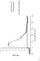
- a graphical representation of the measured intensities and the sigmoid function determined by means of the same measurement for determining the start of the geometric surface after determining X surface is shown as an example using catalyst 1.
- the concentration of the elements was carried out by means of dokimastic decomposition via copper cupellation and subsequent ICP-AES analysis and was calculated in relation to the shaped catalyst body after drying at 120° C. for 2 h.
- the hardness of the shaped catalyst bodies was determined using an 8M tablet hardness tester from Dr. Schleuniger Pharmatron AG determined as an average on 99 pieces of shaped catalyst bodies. Before the measurement, the shaped catalyst bodies were dried at 130° C. for 2 hours. The device settings were the following: Hardness: N Distance to the shaped catalyst body: 5.00mm Time Delay: 0.80s Feed type: 6D Speed: 0.60mm/s
- 7.0 g of an aqueous cesium aurate solution (4.7 wt .-% Au) were diluted with deionized water to 50 g of coating solution and this in the coater at a spray rate of 4 g / min and a temperature of 70°C applied to the catalyst support in a first coating step.
- a mixture of 2.7 g of an aqueous cesium aurate solution (4.7% by weight Au) and 38.9 g of a tetrammine palladium dihydroxide solution (3.4% by weight Pd) with deionized water was applied diluted to 80 g of coating solution and applied to the catalyst support at a spray rate of 4 g/min and at a temperature of 70°C.
- the catalyst supports were kept in a fluidized bed. After renewed static drying in the fluidized bed dryer (90° C./35 min), the shaped catalyst body was statically reduced for 45 min at 100° C. with forming gas (2% H 2 in N 2 ) in the tube furnace.
- the noble metal distribution was determined using a LEO 1530 scanning electron microscope, equipped with an energy-dispersive spectrometer from Bruker AXS. To measure the noble metal concentration across the thickness of the shell, a shaped catalyst body was cut through, glued to an aluminum sample holder and then coated with carbon. A nitrogen-free silicon drift chamber detector (XFlash ® 410) with an energy resolution of 125 eV for the manganese K-alpha line was used as the detector.
- the maximum of the Pd concentration was 23 microns, the maximum of the Au concentration was 25 microns below the geometric surface of the coated catalyst.
- the shell thickness for Pd was 130 microns, that for Au was 93 microns.
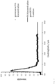
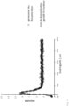
- the curve shape of the Pd concentrations based on the measured values as well as values obtained by the corresponding fit function is in 2 shown, the curve of the Au concentrations based on the measured values as well as after adjustment by the appropriate fit function is in 3 shown. In 4 both curves of the fitted function are shown, whereby the values of the Au concentration were multiplied by a factor of 7 for better comparability.
- 7.0 g of an aqueous cesium aurate solution (4.7% by weight Au) were diluted with deionized water to 50 g of coating solution and this was applied in the coater at a spray rate of 4 g/min and a temperature of 70.degree the catalyst supports are applied in a first coating step.
- a mixture of 2.4 g of an aqueous cesium aurate solution (4.7% by weight Au) and 38.9 g of a tetrammine palladium dihydroxide solution (3.4% by weight Pd) with deionized water was applied diluted to 80 g of coating solution and applied to the catalyst support at a spray rate of 4 g/min and at a temperature of 70°C.
- the catalyst supports were kept in a fluidized bed. After renewed static drying in the fluidized bed dryer (90°C/35 min) the shaped catalyst body was statically reduced for 45 min at 100° C. with forming gas (2% H 2 in N 2 ) in the tube furnace.
- the noble metal distribution was determined as in Example 1.
- the maximum of the Pd concentration and the maximum of the Au concentration were 30 micrometers below the geometric, macroscopic surface of the coated catalyst.
- the shell thickness for Pd was 129 microns, that for Au was 75 microns.
- both curves of the Pd and Au concentrations are shown based on their fitted functions, whereby the values of the Au concentration were multiplied by a factor of 5 for better comparability.
- 7.0 g of an aqueous cesium aurate solution (4.7% by weight Au) were diluted with deionized water to 50 g of coating solution and this was applied in the coater at a spray rate of 4 g/min and a temperature of 71.degree the carrier body is applied in a first coating step.
- a mixture of 2.4 g of an aqueous cesium aurate solution (4.7% by weight Au) and 38.9 g of a tetrammine palladium dihydroxide solution (3.4% by weight Pd) with deionized water was applied diluted to 80 g of coating solution and applied to the catalyst support at a spray rate of 4 g/min and at a temperature of 70°C.
- the catalyst supports continued to be kept in a fluidized bed. After renewed static drying in the fluidized bed dryer (90° C./35 min), the catalyst was statically reduced for 45 min at 100° C. with forming gas (2% H 2 in N 2 ) in the tube furnace.
- the noble metal distribution was determined as in example 1.
- the maximum of the Pd concentration was 43 micrometers, the maximum of the Au concentration was 31 micrometers below the surface of the coated catalyst.
- the shell thickness for Pd was 183 microns, that for Au was 148 microns.
- Fig.6 both curves of the Pd and Au concentrations are shown based on their fitted functions, whereby the values of the Au concentration were multiplied by a factor of 8 for better comparability.
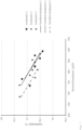
- Table 1 and figure 7 show the selectivity and activity of catalysts 1, 2, and 3 as a function of O 2 conversion. This clearly shows that the catalysts 1 and 2 produced according to the invention have a much higher activity, selectivity (at the same activity level) and productivity than the comparative catalyst catalyst 3. This is also shown in 7 illustrated, in which a plot of the selectivity to VAM is shown as a function of the space-time yield.
Priority Applications (2)
| Application Number | Priority Date | Filing Date | Title |
|---|---|---|---|
| EP21216647.4A EP4201519A1 (fr) | 2021-12-21 | 2021-12-21 | Catalyseur sous enveloppe destiné à la production d'esters carboniques d'alcényle à distribution améliorée de pd et d'au |
| PCT/EP2022/085191 WO2023117495A1 (fr) | 2021-12-21 | 2022-12-09 | Catalyseur à enveloppe pour production d'esters d'alcényle d'acide carboxylique ayant une distribution pd et au améliorée |
Applications Claiming Priority (1)
| Application Number | Priority Date | Filing Date | Title |
|---|---|---|---|
| EP21216647.4A EP4201519A1 (fr) | 2021-12-21 | 2021-12-21 | Catalyseur sous enveloppe destiné à la production d'esters carboniques d'alcényle à distribution améliorée de pd et d'au |
Publications (1)
| Publication Number | Publication Date |
|---|---|
| EP4201519A1 true EP4201519A1 (fr) | 2023-06-28 |
Family
ID=79021604
Family Applications (1)
| Application Number | Title | Priority Date | Filing Date |
|---|---|---|---|
| EP21216647.4A Pending EP4201519A1 (fr) | 2021-12-21 | 2021-12-21 | Catalyseur sous enveloppe destiné à la production d'esters carboniques d'alcényle à distribution améliorée de pd et d'au |
Country Status (2)
| Country | Link |
|---|---|
| EP (1) | EP4201519A1 (fr) |
| WO (1) | WO2023117495A1 (fr) |
Citations (4)
| Publication number | Priority date | Publication date | Assignee | Title |
|---|---|---|---|---|
| US5066365A (en) | 1989-10-17 | 1991-11-19 | Hoechst Aktiengesellschaft | Process for the isolation of vinyl acetate by distillation |
| WO2005065821A1 (fr) | 2003-12-19 | 2005-07-21 | Celanese International Corporation | Materiau de support stratifie pour catalyseurs |
| WO2008145388A1 (fr) | 2007-05-31 | 2008-12-04 | Süd-Chemie AG | Procédé de production d'un catalyseur sous enveloppe et catalyseur sous enveloppe |
| DE102012003232A1 (de) * | 2012-02-20 | 2013-08-22 | Clariant Produkte (Deutschland) Gmbh | Nachvergoldung von Pd-Au-gecoateten Schalenkatalysatoren |
-
2021
- 2021-12-21 EP EP21216647.4A patent/EP4201519A1/fr active Pending
-
2022
- 2022-12-09 WO PCT/EP2022/085191 patent/WO2023117495A1/fr unknown
Patent Citations (4)
| Publication number | Priority date | Publication date | Assignee | Title |
|---|---|---|---|---|
| US5066365A (en) | 1989-10-17 | 1991-11-19 | Hoechst Aktiengesellschaft | Process for the isolation of vinyl acetate by distillation |
| WO2005065821A1 (fr) | 2003-12-19 | 2005-07-21 | Celanese International Corporation | Materiau de support stratifie pour catalyseurs |
| WO2008145388A1 (fr) | 2007-05-31 | 2008-12-04 | Süd-Chemie AG | Procédé de production d'un catalyseur sous enveloppe et catalyseur sous enveloppe |
| DE102012003232A1 (de) * | 2012-02-20 | 2013-08-22 | Clariant Produkte (Deutschland) Gmbh | Nachvergoldung von Pd-Au-gecoateten Schalenkatalysatoren |
Non-Patent Citations (2)
| Title |
|---|
| "Römpp, Lexikon Chemie", vol. 10, GEORG THIEME VERLAG |
| HOLLEMANN WIBERGDE GRUYTER: "Lehrbuch der anorganischen Chemie", 2007 |
Also Published As
| Publication number | Publication date |
|---|---|
| WO2023117495A1 (fr) | 2023-06-29 |
Similar Documents
| Publication | Publication Date | Title |
|---|---|---|
| EP2155382B1 (fr) | Procédé de production d'un catalyseur sous enveloppe, catalyseur sous enveloppe et son utilisation | |
| EP2158035B1 (fr) | Support de catalyseur dopé à l'oxyde de zirconium, procédé de production dudit support de catalyseur et catalyseur contenant un support de catalyseur dopé à l'oxyde de zirconium | |
| WO2008145389A2 (fr) | Catalyseur sous enveloppe servant à la production de vam, procédé de production et d'utilisation dudit catalyseur | |
| WO2008145395A2 (fr) | CATALYSEUR DOPÉ SOUS ENVELOPPE Pd/Au, PROCÉDÉ DE PRODUCTION ET D'UTILISATION DUDIT CATALYSEUR | |
| WO2008145392A2 (fr) | CATALYSEUR SOUS ENVELOPPE Pd/Au À TENEUR EN HfO2, PROCÉDÉ DE PRODUCTION ET D'UTILISATION DUDIT CATALYSEUR | |
| EP2158037A2 (fr) | Procédé de production d'un catalyseur sous enveloppe et catalyseur sous enveloppe | |
| WO2001072415A1 (fr) | Catalyseurs a coque, leur procede de production et leur utilisation | |
| WO2012004334A2 (fr) | Procédé de production d'un catalyseur enrobé et catalyseur enrobé | |
| DE102013015436A1 (de) | Kupfer-promotierter Schalenkatalysator zur Herstellung von Alkenylcarbonsäureestern | |
| EP2370206B1 (fr) | Support de catalyseur, procédé de production dudit support et son utilisation | |
| DE102011101459A1 (de) | Verfahren zur Herstellung eines metallhaltigen Schalenkatalysators ohne Zwischenkalzinierung | |
| DE102012008715A1 (de) | Herstellung von Schalenkatalysatoren in einer Beschichtungsvorrichtung | |
| EP2817097A1 (fr) | Dorure ultérieure de catalyseurs enrobés revêtus de pd-au | |
| EP2817094B1 (fr) | Prédorure de catalyseurs enrobés revêtus de pd-au | |
| WO2010060649A2 (fr) | Catalyseur à enveloppe, procédé de production dudit catalyseur et son utilisation | |
| EP4201519A1 (fr) | Catalyseur sous enveloppe destiné à la production d'esters carboniques d'alcényle à distribution améliorée de pd et d'au | |
| WO2008151731A1 (fr) | Procédé de production d'un catalyseur sous enveloppe à l'aide d'un mélange basique ou acide | |
| EP4201523A1 (fr) | Catalyseur sous enveloppe destiné à la production d'esters carboniques d'alcényle à distribution améliorée de pd | |
| WO2008145386A2 (fr) | Procédé de production d'un catalyseur sous enveloppe | |
| DE102011018532A1 (de) | Basische Katalysatorträgerkörper mit niedriger Oberfläche |
Legal Events
| Date | Code | Title | Description |
|---|---|---|---|
| PUAI | Public reference made under article 153(3) epc to a published international application that has entered the european phase |
Free format text: ORIGINAL CODE: 0009012 |
|
| STAA | Information on the status of an ep patent application or granted ep patent |
Free format text: STATUS: THE APPLICATION HAS BEEN PUBLISHED |
|
| AK | Designated contracting states |
Kind code of ref document: A1 Designated state(s): AL AT BE BG CH CY CZ DE DK EE ES FI FR GB GR HR HU IE IS IT LI LT LU LV MC MK MT NL NO PL PT RO RS SE SI SK SM TR |
|
| STAA | Information on the status of an ep patent application or granted ep patent |
Free format text: STATUS: REQUEST FOR EXAMINATION WAS MADE |
|
| 17P | Request for examination filed |
Effective date: 20240102 |
|
| RBV | Designated contracting states (corrected) |
Designated state(s): AL AT BE BG CH CY CZ DE DK EE ES FI FR GB GR HR HU IE IS IT LI LT LU LV MC MK MT NL NO PL PT RO RS SE SI SK SM TR |