EP4201473B1 - System zur energieverbrauchsreduzierung für konnektivität medizinischer vorrichtungen - Google Patents
System zur energieverbrauchsreduzierung für konnektivität medizinischer vorrichtungen Download PDFInfo
- Publication number
- EP4201473B1 EP4201473B1 EP22214685.4A EP22214685A EP4201473B1 EP 4201473 B1 EP4201473 B1 EP 4201473B1 EP 22214685 A EP22214685 A EP 22214685A EP 4201473 B1 EP4201473 B1 EP 4201473B1
- Authority
- EP
- European Patent Office
- Prior art keywords
- external device
- medical device
- information
- connection
- imd
- Prior art date
- Legal status (The legal status is an assumption and is not a legal conclusion. Google has not performed a legal analysis and makes no representation as to the accuracy of the status listed.)
- Active
Links
Images










Classifications
-
- A—HUMAN NECESSITIES
- A61—MEDICAL OR VETERINARY SCIENCE; HYGIENE
- A61N—ELECTROTHERAPY; MAGNETOTHERAPY; RADIATION THERAPY; ULTRASOUND THERAPY
- A61N1/00—Electrotherapy; Circuits therefor
- A61N1/02—Details
- A61N1/08—Arrangements or circuits for monitoring, protecting, controlling or indicating
- A61N1/086—Magnetic resonance imaging [MRI] compatible leads
-
- H—ELECTRICITY
- H04—ELECTRIC COMMUNICATION TECHNIQUE
- H04W—WIRELESS COMMUNICATION NETWORKS
- H04W48/00—Access restriction; Network selection; Access point selection
- H04W48/08—Access restriction or access information delivery, e.g. discovery data delivery
- H04W48/10—Access restriction or access information delivery, e.g. discovery data delivery using broadcasted information
-
- A—HUMAN NECESSITIES
- A61—MEDICAL OR VETERINARY SCIENCE; HYGIENE
- A61N—ELECTROTHERAPY; MAGNETOTHERAPY; RADIATION THERAPY; ULTRASOUND THERAPY
- A61N1/00—Electrotherapy; Circuits therefor
- A61N1/02—Details
- A61N1/04—Electrodes
- A61N1/05—Electrodes for implantation or insertion into the body, e.g. heart electrode
- A61N1/0526—Head electrodes
- A61N1/0529—Electrodes for brain stimulation
- A61N1/0534—Electrodes for deep brain stimulation
-
- A—HUMAN NECESSITIES
- A61—MEDICAL OR VETERINARY SCIENCE; HYGIENE
- A61N—ELECTROTHERAPY; MAGNETOTHERAPY; RADIATION THERAPY; ULTRASOUND THERAPY
- A61N1/00—Electrotherapy; Circuits therefor
- A61N1/02—Details
- A61N1/04—Electrodes
- A61N1/05—Electrodes for implantation or insertion into the body, e.g. heart electrode
- A61N1/0551—Spinal or peripheral nerve electrodes
-
- A—HUMAN NECESSITIES
- A61—MEDICAL OR VETERINARY SCIENCE; HYGIENE
- A61N—ELECTROTHERAPY; MAGNETOTHERAPY; RADIATION THERAPY; ULTRASOUND THERAPY
- A61N1/00—Electrotherapy; Circuits therefor
- A61N1/18—Applying electric currents by contact electrodes
- A61N1/32—Applying electric currents by contact electrodes alternating or intermittent currents
- A61N1/36—Applying electric currents by contact electrodes alternating or intermittent currents for stimulation
- A61N1/3605—Implantable neurostimulators for stimulating central or peripheral nerve system
- A61N1/36128—Control systems
- A61N1/36142—Control systems for improving safety
-
- A—HUMAN NECESSITIES
- A61—MEDICAL OR VETERINARY SCIENCE; HYGIENE
- A61N—ELECTROTHERAPY; MAGNETOTHERAPY; RADIATION THERAPY; ULTRASOUND THERAPY
- A61N1/00—Electrotherapy; Circuits therefor
- A61N1/18—Applying electric currents by contact electrodes
- A61N1/32—Applying electric currents by contact electrodes alternating or intermittent currents
- A61N1/36—Applying electric currents by contact electrodes alternating or intermittent currents for stimulation
- A61N1/372—Arrangements in connection with the implantation of stimulators
- A61N1/37211—Means for communicating with stimulators
- A61N1/37235—Aspects of the external programmer
-
- H—ELECTRICITY
- H04—ELECTRIC COMMUNICATION TECHNIQUE
- H04W—WIRELESS COMMUNICATION NETWORKS
- H04W52/00—Power management, e.g. Transmission Power Control [TPC] or power classes
- H04W52/02—Power saving arrangements
- H04W52/0209—Power saving arrangements in terminal devices
- H04W52/0225—Power saving arrangements in terminal devices using monitoring of external events, e.g. the presence of a signal
- H04W52/0229—Power saving arrangements in terminal devices using monitoring of external events, e.g. the presence of a signal where the received signal is a wanted signal
-
- H—ELECTRICITY
- H04—ELECTRIC COMMUNICATION TECHNIQUE
- H04W—WIRELESS COMMUNICATION NETWORKS
- H04W76/00—Connection management
- H04W76/10—Connection setup
-
- A—HUMAN NECESSITIES
- A61—MEDICAL OR VETERINARY SCIENCE; HYGIENE
- A61N—ELECTROTHERAPY; MAGNETOTHERAPY; RADIATION THERAPY; ULTRASOUND THERAPY
- A61N1/00—Electrotherapy; Circuits therefor
- A61N1/18—Applying electric currents by contact electrodes
- A61N1/32—Applying electric currents by contact electrodes alternating or intermittent currents
- A61N1/36—Applying electric currents by contact electrodes alternating or intermittent currents for stimulation
- A61N1/362—Heart stimulators
- A61N1/37—Monitoring; Protecting
- A61N1/3718—Monitoring of or protection against external electromagnetic fields or currents
-
- A—HUMAN NECESSITIES
- A61—MEDICAL OR VETERINARY SCIENCE; HYGIENE
- A61N—ELECTROTHERAPY; MAGNETOTHERAPY; RADIATION THERAPY; ULTRASOUND THERAPY
- A61N1/00—Electrotherapy; Circuits therefor
- A61N1/18—Applying electric currents by contact electrodes
- A61N1/32—Applying electric currents by contact electrodes alternating or intermittent currents
- A61N1/38—Applying electric currents by contact electrodes alternating or intermittent currents for producing shock effects
- A61N1/39—Heart defibrillators
- A61N1/3925—Monitoring; Protecting
Definitions
- This disclosure generally relates to electrical stimulation therapy.
- Medical devices may be external or implanted, and may be used to sense neural signals (e.g., central and peripheral nerves) and/or deliver electrical stimulation therapy to various tissue sites of a patient to treat a variety of symptoms or conditions such as, for example, one or more of chronic pain, tremor, Parkinson's disease, other movement disorders, epilepsy, urinary or fecal incontinence, sexual dysfunction, obesity, gastroparesis, sleep apnea, neural control of prosthetic devices, or stimulation to provide peripheral sensation.
- a medical device delivers electrical stimulation therapy via one or more leads that include electrodes located proximate to target locations associated with the brain, the spinal cord, pelvic nerves, peripheral nerves, or the gastrointestinal tract of a patient.
- the electrodes used for stimulation may be on one or more leads.
- the electrodes may include one or more leads and an electrode on a stimulator housing located remotely from the target site (e.g., near clavicle). It may be possible to use leadless stimulation using electrodes mounted on the stimulator housing.
- electrical stimulation is used in different therapeutic applications, such as deep brain stimulation (DBS), spinal cord stimulation (SCS), pelvic stimulation, gastric stimulation, or peripheral nerve field stimulation (PNFS).
- DBS deep brain stimulation
- SCS spinal cord stimulation
- PNFS peripheral nerve field stimulation
- a clinician may select values for a number of programmable parameters in order to define the electrical stimulation therapy to be delivered by the implantable stimulator to a patient.
- the clinician may select one or more electrodes for delivery of the stimulation, a polarity of each selected electrode, a voltage or current pulse amplitude, a pulse width, and a pulse rate as stimulation parameters.
- a set of parameters such as a set including electrode combination, electrode polarity, amplitude, pulse width, and pulse rate, may be referred to as a program in the sense that they define the electrical stimulation therapy to be delivered to the patient.
- US 2017/312530 A1 relates to managing telemetry communication modes of an implantable device.
- US 2015/209589 A1 relates to methods, implantable medical devices, and systems to continue implementing a special mode of operation after experiencing a device reset.
- WO 2012/057872 A1 relates to an implantable medical device telemetry in a disruptive energy field.
- US 2011/137359 A1 relates to an implantable medical device with automatic tachycardia detection and control in MRI environments.
- US 2011/106204 A1 relates to configuring operating parameters of a medical device based on a type of source of a disruptive energy field.
- US 2010/211123 A1 relates to systems and methods for providing arrythmia therapy in MRI environments.
- US 2009/138058 A1 relates to MRI operation modes for implantable medical devices.
- Claim 1 provides a system. Subject matter described in the present disclosure not falling under the scope of claim 1 does not form part of the claimed subject matter, yet maybe useful for understanding the claimed subject matter.
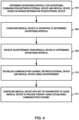
- a system may determine an advertising interval for communication between the external device and the medical device based on the movement of the external device. For instance, the system may determine to reduce the advertising interval from a current advertising interval in response to an increase in, or initiation of, the movement of the external device and increase the advertising interval from the current advertising interval in response to a decrease in, or cessation of, the movement of the external device. In this example, the system may configure the medical device and/or the external device to communicate using the determined advertising interval.
- the system may determine the advertising interval using sensor information that is based on, for example, one or more of the movement of the external device, a detected light level, a detected sound level, or other sensor information.
- the system may help to reduce a time to initiate communication between the medical device and the external device when the user (e.g., a patient, caretaker, or clinician) is likely to request communication.
- the user e.g., a patient, caretaker, or clinician
- the system may reduce or avoid latency in establishing the connection to help to improve the response time and usability of the system.
- the system may also potentially reduce the communication energy drain when the communication is not likely to be needed (e.g., when the user is sleeping or not otherwise interacting with the external device).
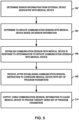
- a system may determine to preemptively initiate a communication session for communication between the external device and the medical device based on sensor information from the external device.
- a communication session may refer to data transmissions between an external device and medical device once connection with a host is established after the advertisement. While examples may refer to a Bluetooth TM session, examples may use other communication sessions.
- the system may determine to initiate the communication session in response to an increase in a movement of the external device.
- the system may determine to initiate the communication session in response to the increase in the movement of the external device and further in response to a determination that the movement has been less than a threshold for a predetermined period of time.
- the medical device may initiate communication between external device and medical device, for example, based on a voice command from the user (e.g., the patient or a caretaker) directly to the medical device which is not using sensor information from external device.
- a voice command from the user (e.g., the patient or a caretaker) directly to the medical device which is not using sensor information from external device.
- this disclosure describes a system comprising telemetry circuitry configured for communication between a medical device and an external device associated with the medical device and processing circuitry.
- the processing circuitry is configured to determine an advertising interval for communication between the external device and the medical device based on sensor information from the external device.
- the processing circuitry is further configured to configure the medical device to advertise at the determined advertising interval.
- this disclosure describes a method comprising determining, with processing circuitry, an advertising interval for communication between the external device and the medical device based on sensor information from the external device. The method further comprises configuring, with the processing circuitry, the medical device to advertise at the determined advertising interval.
- this disclosure describes a computer-readable storage medium having stored thereon instructions that, when executed, cause processing circuitry to determine an advertising interval for communication between an external device and a medical device associated with the external device based on sensor information from the external device and configure the medical device to advertise at the determined advertising interval.
- this disclosure describes a system comprising telemetry circuitry configured for communication between a medical device and an external device associated with the medical device and processing circuitry.
- the processing circuitry is configured to determine to initiate a communication session with the medical device based on sensor information from the external device.
- the processing circuitry is further configured to establish, with the telemetry circuitry, the communication session with the medical device in response to the determination to initiate the communication session with the medical device and receive, after establishing the communication session, an instruction to configure the medical device with at least one program parameter.
- the processing circuitry is further configured to output, using the communication session, information to cause the medical device to provide therapy using the at least one program parameter.
- this disclosure describes a method comprising determining, with processing circuitry, to initiate a communication session with the medical device based on sensor information from the external device.
- the method further comprises establishing, with the processing circuitry, the communication session with the medical device in response to the determination to initiate the communication session with the medical device and receiving, with the processing circuitry, after establishing the communication session, an instruction to configure the medical device with at least one program parameter.
- the method further comprises outputting, with the processing circuitry, using the communication session, information to cause the medical device to provide therapy using the at least one program parameter.
- this disclosure describes a system comprising telemetry circuitry configured for communication between a medical device and an external device associated with the medical device and processing circuitry.
- the processing circuitry is configured to determine an advertising interval between the external device and the medical device based on the sensor information from the external device and configure the medical device to advertise at the determined interval.
- this disclosure describes a method comprising determining, with processing circuitry, an advertising interval for communication between an external device and a medical device associated with the external device based on sensor information from the external device and configuring, with the processing circuitry, the medical device to advertise at the determined advertising interval.
- this disclosure describes a computer-readable storage medium having stored thereon instructions that, when executed, cause processing circuitry to determine to initiate a communication session with a medical device based on sensor information from an external device associated with the medical device, establish the communication session with the medical device in response to the determination to initiate the communication session with the medical device, receive, after establishing the communication session, an instruction to configure the medical device with at least one program parameter, and output, using the communication session, information to cause the medical device to provide therapy using the at least one program parameter.
- This disclosure describes example techniques for systems configured to deliver electrical stimulation therapy (e.g., neuromodulation such as deep brain stimulation (DBS), spinal cord stimulation (SCS), sacral nerve stimulation (SNS), or peripheral nerve stimulation therapy).
- the system may be configured to adjust advertising intervals and the start and end of telemetry sessions based on sensed information.
- Electrical stimulation therapy may be delivered via multiple electrodes of one or more leads (e.g., cylindrical or paddle leads) implanted to provide stimulation in the brain, in the spinal cord, in the sacral nerve, or the percutaneous tibial nerve stimulation of a patient.
- electrical stimulation therapy may be delivered via a leadless device. Electrical stimulation therapy may be adaptively adjusted for a patient using at least one program parameter.
- Neuromodulation telemetry systems may use Bluetooth TM (ISM bands from 2.402 to 2.48 GHz) or other wireless technology protocols (e.g., RF protocols) to implement communication with programming instruments including proprietary external programmers and commercial off-the-shelf instruments such as cellphones and tablets. Access to external instruments may help to enable recharge and product longevity, and may help to prevent high risk procedures like replacement surgeries for implantable devices. Impact of high frequency protocols may be high on device longevity and is directly proportional to connection / advertising intervals. Faster advertising leads to faster connection and reduced latency, but this means higher current drain and reduced device longevity.
- Bluetooth TM ISM bands from 2.402 to 2.48 GHz
- RF protocols wireless technology protocols
- the energy needed to either maintain a distance telemetry session or make an implantable medical device immediately responsive for the user can consume a significant proportion of the energy from an implantable device.
- Techniques described herein may configure a system to use sensors (e.g., an accelerometer, a light sensor, or a microphone) to indicate when a patient is not likely to need a fast connection/response and/or preemptively start initiating connecting to the implantable device before a user request for the connection in order to improve the response time and usability of the system while being able to reduce the communication energy drain when the communication is not likely to be needed (e.g., when the user is sleeping).
- sensors e.g., an accelerometer, a light sensor, or a microphone
- Techniques described herein may configure a system to change an advertising interval (e.g., a Bluetooth TM Low Energy advertising interval or another advertising interval) of the medical device (e.g., an implanted medical device) based on information obtained by the medical device and/or an external programmer (e.g., a patient programmer, a clinician programmer, or a mobile device).
- an advertising interval e.g., a Bluetooth TM Low Energy advertising interval or another advertising interval
- an advertising interval e.g., a Bluetooth TM Low Energy advertising interval or another advertising interval
- an advertising interval e.g., a Bluetooth TM Low Energy advertising interval or another advertising interval
- an advertising interval e.g., a Bluetooth TM Low Energy advertising interval or another advertising interval
- an advertising interval e.g., a Bluetooth TM Low Energy advertising interval or another advertising interval
- the advertising interval can be lengthened, which may potentially save energy. Saving energy may help to optimize telemetry performance and/or efficiency, which can help make the medical device (e.g
- a user may place an external device (e.g., a mobile device such as a cell phone) on a table or other stationary place at night where the accelerometer in the external device does not detect movement. Because the user may move the external device from the stationary place to their hand to program, the accelerometer in the external device may detect movement of the external device.
- the external device if in range of the medical device (e.g., on a bedside table), can output an instruction to the medical device to increase the advertising interval of the medical device for a communication session with the medical device when no movement of the external device is detected.
- the external device may increase the advertising interval based on non-activity/movement of the external device but have the medical device, either through motion or a time of day, decrease its advertising interval (with the external device also decreasing the advertising interval upon movement if the device has not done it already). For example, a patient unexpectedly wakes up at night and wants to change settings and the medical device does not have an accelerometer to know there is movement of the patient.
- the external device may attempt to decrease the advertising interval (e.g., increase the advertising rate) of the implanted device when the external device is first moved.
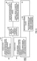
- a system may enable smart connection parameters for communications using an adaptive learning algorithm with inputs like historic daily connection times, sensor information, direct user input, type of other connections, a geographical location, application access, etc.
- the system may implement smart connectivity driving optimized longevity of a battery of the medical device (e.g., an implantable medical device) and an optimized individual tailor-made user experience that reduces or even eliminates a connection latency.
- the user may disable the adaptive learning algorithm at the cost of longevity.
- Techniques described herein may help to allow the medical device to function to optimum performance levels exceling in patient experience while improving device longevity. Techniques described herein may help to allow patients to use an implantable medical device for a longer time, therefore reducing the risk of replacement surgeries.
- Smart connectivity can also be assisted with in-band stings, such as, for example, inductive downlinks over inductive telemetry (e.g., telecoil, Tel-N, or Tel-B) and/or in-band stings (e.g., within a wireless band such as a BLE band) to the implant making the advertising rate temporarily fast to enable faster communications.
- This "sting" can also be used as a manufacturing tool to connect to the correct device faster.
- a sting e.g., an in-band sting or an out-of-band sting
- Stinging may not necessarily include advertisements or handshaking.
- an inductive telemetry device may be placed near an implanted medical device to cause the medical device to establish a connection more quickly than if not for the inductive sting.
- the medical device may "ping" other devices, for example, by outputting an advertisement that another device (e.g., an external device) may listen for in order to determine if there is a device out there for exchanging communications.
- the ping may be a telemetry output from the medical device and may be in-band (e.g., a BLE advertisement) or out-of-band.
- An advertising device may broadcast the advertisement for connection at the advertising interval to two unconnected devices such that more than one device can listen and establish a connection with the advertising device using the advertisement for connection.
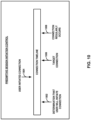
- the advertisement for connection may include information on how to connect with the advertising device, such as, for example, one or more of: (1) media access control (MAC) addresses for the medical device and external device; (2) a real time-point in time for the transfer to start; (3) an indication of a starting frequency; (4) an indication of a hop set; (5) a connection interval; or (6) a connection latency.
- MAC media access control
- FIG. 1 is a conceptual diagram illustrating an example system 100 that includes an implantable medical device (IMD) 106 configured to deliver adaptive deep brain stimulation (DBS) to a patient 112.
- IMD implantable medical device
- DBS adaptive deep brain stimulation
- IMD implantable medical device
- FIG. 1 will refer to an implantable DBS system for purposes of illustration, but without limitation as to other types of medical devices or other therapeutic applications of stimulation.
- one or more components of system 100 may be configured to deliver one or more of deep brain stimulation (DBS), spinal cord stimulation (SCS), sacral neuromodulation (SNS), targeted drug delivery (TDD), pelvic stimulation, gastric stimulation, or peripheral nerve field stimulation (PNFS), or any other stimulation therapy capable of treating a condition of patient 122.
- DBS deep brain stimulation
- SCS spinal cord stimulation
- SNS sacral neuromodulation
- TDD targeted drug delivery
- PNFS peripheral nerve field stimulation
- any other stimulation therapy capable of treating a condition of patient 122.
- DBS may be adaptive in the sense that IMD 106 may adjust, increase, or decrease the magnitude of one or more parameters of the DBS in response to changes in patient activity or movement, a severity of one or more symptoms of a disease of the patient, a presence of one or more side effects due to the DBS, or one or more sensed signals of the patient.
- system 100 is a bi-directional DBS system with capabilities to both deliver stimulation and sense intrinsic neuronal signals.
- System 100 may provide for "closed-loop" therapy where IMD 106 may continuously monitor the state of certain biomarker signals and deliver stimulation according to pre-programmed routines based on the biomarker signals.
- System 100 may be configured to treat a patient condition, such as a movement disorder, neurodegenerative impairment, a mood disorder, or a seizure disorder of patient 112.
- Patient 112 ordinarily is a human patient. In some cases, however, therapy system 100 may be applied to other mammalian or non-mammalian, non-human patients.
- therapy system 100 may provide therapy to manage symptoms of other patient conditions, such as, but not limited to, seizure disorders (e.g., epilepsy) or mood (or psychological) disorders (e.g., major depressive disorder (MDD), bipolar disorder, anxiety disorders, post-traumatic stress disorder, dysthymic disorder, and obsessive-compulsive disorder (OCD)) as well as, for example, neural control of prosthetic devices or stimulation to provide sensory feedback to the patients. At least some of these disorders may be manifested in one or more patient movement behaviors.
- seizure disorders e.g., epilepsy
- mood (or psychological) disorders e.g., major depressive disorder (MDD), bipolar disorder, anxiety disorders, post-traumatic stress disorder, dysthymic disorder, and obsessive-compulsive disorder (OCD)
- OCD obsessive-compulsive disorder
- a movement disorder or other neurodegenerative impairment may include symptoms such as, for example, muscle control impairment, motion impairment or other movement problems, such as rigidity, spasticity, bradykinesia, rhythmic hyperkinesia, nonrhythmic hyperkinesia, and akinesia.
- the movement disorder may be a symptom of Parkinson's disease.
- the movement disorder may be attributable to other patient conditions.
- Example therapy system 100 includes medical device external device 104, implantable medical device (IMD) 106, lead extension 110, one or more leads 114A and 114B with respective sets of one or more electrodes 116, 118.
- electrodes 116, 118 of leads 114A, 114B are positioned to deliver electrical stimulation to a tissue site within brain 120, such as a deep brain site under the dura mater of brain 120 of patient 112.
- delivery of stimulation to one or more regions of brain 120 such as the subthalamic nucleus, globus pallidus or thalamus, may be an effective treatment to manage movement disorders, such as Parkinson's disease.
- IMD 106 includes a therapy module (e.g., which may include processing circuitry, signal generation circuitry or other electrical circuitry configured to perform the functions attributed to IMD 106) that includes a stimulation generator configured to generate and deliver electrical stimulation therapy to patient 112 via a subset of electrodes 116, 118 of leads 114A and 114B, respectively.
- the subset of electrodes 116, 118 that are used to deliver electrical stimulation to patient 112, and, in some cases, the polarity of the subset of electrodes 116, 118, may be referred to as a stimulation electrode combination.
- the stimulation electrode combination can be selected for a particular patient 112 and target tissue site (e.g., selected based on the patient condition).
- the group of electrodes 116, 118 includes at least one electrode and can include a plurality of electrodes.
- the plurality of electrodes 116 and/or 118 may have a complex electrode geometry such that two or more electrodes are located at different positions around the perimeter of the respective lead.
- the neurological brain signals that are used to select a stimulation electrode combination may be sensed within the same region of brain 120 as the target tissue site for the electrical stimulation.
- these tissue sites may include tissue sites within anatomical structures such as the thalamus, subthalamic nucleus or globus pallidus of brain 120, as well as other target tissue sites.
- the specific target tissue sites and/or regions within brain 120 may be selected based on the patient condition.
- both stimulation electrode combinations and sense electrode combinations may be selected from the same set of electrodes 116, 118.
- the electrodes used for delivering electrical stimulation may be different than or the same as the electrodes used for sensing neurological brain signals.
- Electrical stimulation generated by IMD 106 may be configured to manage a variety of disorders and conditions.
- the stimulation generator of IMD 106 is configured to generate and deliver electrical stimulation pulses to patient 112 via electrodes of a selected stimulation electrode combination.
- the stimulation generator of IMD 106 may be configured to generate and deliver a continuous wave signal, e.g., a sine wave or triangle wave. In either case, a stimulation generator within IMD 106 may generate the electrical stimulation therapy for DBS according to a selected therapy program.
- a therapy program may include a set of therapy parameter values (e.g., stimulation parameters), such as a stimulation electrode combination for delivering stimulation to patient 112, pulse frequency, pulse width, and a current or voltage amplitude of the pulses.
- the electrode combination may indicate the specific electrodes 116, 118 that are selected to deliver stimulation signals to tissue of patient 112 and the respective polarities of the selected electrodes.
- the electrical stimulation generated by IMD 106 may generate, for example, burst pulses, interleaved pulses, or concurrent pulses.
- electrodes 116, 118 may be radially-segmented DBS arrays (rDBSA) of electrodes.
- Radially-segmented DBS arrays refer to electrodes that are segmented radially along the lead.
- leads 114A and 114B may include a first set of electrodes arranged circumferentially around leads 114A and 114B that are all at the same height level on leads 114A and 114B. Each of the electrodes in the first set of electrodes is a separate segmented electrode and form a level of radially-segmented array of electrodes.
- Leads 114A and 114B may include a second set of electrodes arranged circumferentially around leads 114A and 114B that are all at the same height level on leads 114A and 114B.
- Each of the electrodes in the first set of electrodes is a separate segmented electrode and form a level of radially-segmented array of electrodes.
- the rDBSA electrodes may be beneficial for directional stimulation and sensing.
- IMD 106 may be implanted within a subcutaneous pocket above the clavicle, or, alternatively, on or within cranium 122 or at any other suitable site within patient 112. Generally, IMD 106 is constructed of a biocompatible material that resists corrosion and degradation from bodily fluids. IMD 106 may comprise a hermetic housing to substantially enclose components, such as a processor, therapy module, and memory.
- implanted lead extension 110 is coupled to IMD 106 via connector 108 (also referred to as a connector block or a header of IMD 106).
- lead extension 110 traverses from the implant site of IMD 106 and along the neck of patient 112 to cranium 122 of patient 112 to access brain 120.
- leads 114A and 114B are implanted within the right and left hemispheres (or in just one hemisphere in some examples), respectively, of patient 112 in order to deliver electrical stimulation to one or more regions of brain 120, which may be selected based on the patient condition or disorder controlled by therapy system 100.
- the specific target tissue site and the stimulation electrodes used to deliver stimulation to the target tissue site may be selected, e.g., according to the identified patient behaviors and/or other sensed patient parameters.
- the target tissue site may be the location of the oscillatory signal source that generates the bioelectric signal having a signal component in the beta frequency band.
- the stimulation electrodes used to deliver stimulation to the target tissue site may be those that are most proximal to the oscillatory signal source, e.g., using the example techniques described in this disclosure.
- Other lead 114 and IMD 106 implant sites are contemplated depending on clinical application or target tissue/nerve.
- IMD 106 may be implanted on or within cranium 122, in some examples.
- Leads 114A and 114B may be implanted within the same hemisphere or IMD 106 may be coupled to a single lead implanted in a single hemisphere, in some examples.
- Existing lead sets include axial leads carrying ring electrodes disposed at different axial positions and so-called "paddle" leads carrying planar arrays of electrodes. Selection of electrode combinations within an axial lead, a paddle lead, or among two or more different leads presents a challenge to the clinician. In some examples, more complex lead array geometries may be used. Pelvic stimulation may use cuff electrodes wrapped around the sacral (or other pelvic) nerve.
- leads 114 are shown in FIG. 1 as being coupled to a common lead extension 110, in other examples, leads 114 may be coupled to IMD 106 via separate lead extensions or directly to connector 108. Leads 114 may be positioned to deliver electrical stimulation to one or more target tissue sites within brain 120 to manage patient symptoms associated with a movement disorder of patient 112. Leads 114 may be implanted to position electrodes 116, 118 at desired locations of brain 120 through respective holes in cranium 122. Leads 114 may be placed at any location within brain 120 such that electrodes 116, 118 are capable of providing electrical stimulation to target tissue sites within brain 120 during treatment.
- electrodes 116, 118 may be surgically implanted under the dura mater of brain 120 or within the cerebral cortex of brain 120 via a burr hole in cranium 122 of patient 112, and electrically coupled to IMD 106 via one or more leads 114.
- electrodes 116, 118 of leads 114 are shown as ring electrodes. Ring electrodes may be used in DBS applications because ring electrodes are relatively simple to program and are capable of delivering an electrical field to any tissue adjacent to electrodes 116, 118. In other examples, electrodes 116, 118 may have different configurations. For example, at least some of the electrodes 116, 118 of leads 114 may have a complex electrode array geometry that is capable of producing shaped electrical fields. The complex electrode array geometry may include multiple electrodes (e.g., partial ring or segmented electrodes) around the outer perimeter of each lead 114, rather than one ring electrode. In this manner, electrical stimulation may be directed in a specific direction from leads 114 to enhance therapy efficacy and reduce possible adverse side effects from stimulating a large volume of tissue.
- a housing of IMD 106 may include one or more stimulation and/or sensing electrodes.
- leads 114 may have shapes other than elongated cylinders as shown in FIG. 1 .
- leads 114 may be paddle leads, spherical leads, bendable leads, or any other type of shape effective in treating patient 112 and/or minimizing invasiveness of leads 114.
- IMD 106 includes a memory to store a plurality of therapy programs that each define a set of therapy parameter values. In some examples, IMD 106 may select a therapy program from the memory based on various parameters, such as sensed patient parameters and the identified patient behaviors. IMD 106 may generate electrical stimulation based on the parameters of the selected therapy program to manage the patient symptoms associated with a movement disorder.
- the clinician may also store therapy programs within IMD 106 with the aid of external device 104.
- the clinician may determine one or more therapy programs that may provide efficacious therapy to patient 112 to address symptoms associated with the patient condition, and, in some cases, specific to one or more different patient states, such as a sleep state, movement state or rest state.
- the clinician may select one or more stimulation electrode combinations with which stimulation is delivered to brain 120.
- the clinician may evaluate the efficacy of the specific program being evaluated based on feedback provided by patient 112 or based on one or more physiological parameters of patient 112 (e.g., muscle activity, muscle tone, rigidity, tremor, etc.).
- identified patient behavior from video information may be used as feedback during the initial and subsequent programming sessions.
- External device 104 may assist the clinician in the creation/identification of therapy programs by providing a methodical system for identifying potentially beneficial therapy parameter values.
- External device 104 may also be configured for use by patient 112.
- external device 104 may have limited functionality (compared to a clinician programmer) in order to prevent patient 112 from altering critical functions of IMD 106 or applications that may be detrimental to patient 112. In this manner, external device 104 may only allow patient 112 to adjust values for certain therapy parameters or set an available range of values for a particular therapy parameter. For example, external device 104 may only allow patient 112 to adjust an amplitude or an intensity (by combination or amplitude, pulse width and/or pulse rate).
- Therapy system 100 may be implemented to provide chronic stimulation therapy to patient 112 over the course of several months or years. However, system 100 may also be employed on a trial basis to evaluate therapy before committing to full implantation. If implemented temporarily, some components of system 100 may not be implanted within patient 112. For example, patient 112 may be fitted with an external medical device, such as a trial stimulator, rather than IMD 106. The external medical device may be coupled to percutaneous leads or to implanted leads via a percutaneous extension. If the trial stimulator indicates DBS system 100 provides effective treatment to patient 112, the clinician may implant a chronic stimulator within patient 112 for relatively long-term treatment.
- an external medical device such as a trial stimulator
- the set of electrodes 116 includes electrodes 116A, 116B, 116C, and 116D
- the set of electrodes 118 includes electrodes 118A, 118B, 118C, and 118D.
- Processing circuitry 210 may control individual voltage or current sources and sinks coupled to respective electrodes 116, 118, functioning as cathodes or anodes, to delivery stimulation signals to patient tissue. In other examples, processing circuitry may control switch circuitry to apply the stimulation signals generated by stimulation generation circuitry 202 to selected combinations of electrodes 116, 118.
- leads 114 may include radially-segmented DBS arrays (rDBSA) of electrodes.
- rDBSA radially-segmented DBS arrays
- Below the first ring electrode there may be three segmented electrodes of electrodes 116 around the perimeter of lead 114A at a second longitudinal location on lead 114A (e.g., location B).
- Below the three segmented electrodes there may be another set of three segmented electrodes of electrodes 116 around the perimeter of lead 114A at a third longitudinal location of lead 114A (e.g., location C).
- Below the three segmented electrodes there may be a second ring electrode of electrodes 116 around the perimeter of lead 114A (e.g., location D).
- Electrodes 118 may be similarly positioned along lead 114B.
- the electrodes 116, 118 may be electrically coupled to switch circuitry via respective wires that are straight or coiled within the housing of the lead and run to a connector at the proximal end of the lead.
- each of the electrodes 116, 118 of the leads 114 may be electrodes deposited on a thin film.
- the thin film may include an electrically conductive trace for each electrode that runs the length of the thin film to a proximal end connector.
- the thin film may then be wrapped (e.g., a helical wrap) around an internal member to form the leads 114.
- the neurons generate the signals, and if measured at depth, it is LFP, if measured on the coretex, it is ECoG, if on the scalp, it is EEG.
- the bioelectric signals may be formed by one or more oscillatory signal sources.
- the set of electrodes 116 and 118 that are most proximate to the oscillatory signal sources are good candidates to use for delivering therapy.
- sensing circuitry 204 may sense EMG, ECAP, Electrogram Guided Myocardial Advanced Phenotypings (EMAPs), or other neural or physiological signals generated in response to a stimulation or in response to other evocation, muscle movement, user-evoked signals, etc.
- incontinence therapy may involve sensing muscle and/or neural signals.
- Telemetry circuitry 208 supports wireless communication (e.g., using Bluetooth TM , Wi-Fi TM , Near-Field Communication (NFC), Near Field Magnetic Induction (NFMI), Long Term Evolution, 5th generation (LTE/5G), or MedRadio (MICS: Medical Implant Communication Service, MEDS: Medical External Device Service, MBAD: Medical Body Area Network)) between IMD 106 and an external device 104 or another computing device under the control of processing circuitry 210.
- telemetry circuitry 208 supports a telemetry frequency that may correspond to a high frequency or radio frequency, which may be a radio frequency established via Bluetooth, Wi-Fi, Near-Field Communication (NFC), 175KHz inductive telemetry, or MICS, for example.
- Telemetry circuitry 208 may be configured to receive an inductive sting.
- Processing circuitry 210 of IMD 106 may receive, as updates to programs (e.g., at least one program parameter), values for various stimulation parameters such as magnitude and electrode combination, from external device 104 via telemetry circuitry 208.
- the updates to the therapy programs may be stored within therapy programs 214 portion of memory 211.
- Telemetry circuitry 208 in IMD 106, as well as telemetry modules in other devices and systems described herein, such as external device 104 may accomplish communication by radiofrequency (RF) communication techniques (e.g., Bluetooth, Wi-Fi, Near-Field Communication (NFC), or MICS).
- RF radiofrequency
- Telemetry circuitry 208 may periodically output an advertisement for a connection at an advertising interval (e.g., less than 100 ms, 100 ms to 500 ms, 1 second, more than 1 second, etc.) with an optional random delay.
- the advertisement may include information on how to connect with the advertising device, such as, for example, one or more of: (1) media access control (MAC) addresses for the medical device and external device; (2) a real time-point in time for the transfer to start; (3) an indication of a starting frequency; (4) an indication of a hop set; (5) a connection interval; or (6) a connection latency.
- MAC media access control
- telemetry circuitry 208 may receive the advertisement and connect with another device (e.g., external device 104) using the received advertisement (e.g., using a starting frequency and hop set of the received advertising packet).
- Telemetry circuitry 208 may be configured to output an advertisement, such as, advertisement for a wireless communication session or advertisement compliant with another protocol.
- telemetry circuitry 208 may output the advertisement at an advertising interval.
- the advertising interval may include a Bluetooth Low Energy advertising interval.
- Telemetry circuitry 208 may ping external device 104.
- telemetry circuitry 208 may output an advertisement or advertisement package that external device 104 or another device listens for in order to know if there is a device for exchanging communications.
- the telemetry circuitry 208 may output the advertisement in response to a sting and/or may periodically output the advertisement using an advertising interval (e.g., with a random delay).
- IMD 106 may be configured to generate second information.
- processing circuitry 210 may be configured to determine the second information based on one or more of a sensor output from IMD 106, motion information generated by an accelerometer of sensing circuitry 204, spacial information and/or posture information generated with an accelerometer of sensing circuitry 204, sleep information generated with sensing circuitry 204, a magnetic resonance imaging (MRI) signal generated by sensing circuitry 204, or a state of a connection between IMD 106 with external device 104 or another device of system 100.
- MRI magnetic resonance imaging
- external device 104 may be configured to use sensor information detected by external device 104 to determine an advertising interval for communication between external device 104 and IMD 106.
- external device 104 may configure telemetry circuitry 208 to advertise (e.g., wireless session information) at the determined advertising interval.
- Telemetry circuitry 208 may advertise the advertisement at the determined advertising interval.
- system 100 may help to reduce a time to initiate communication between IMD 106 to external device 104 when the user (e.g., patient 112, a caretaker of patient 112, or a clinician associated with patient 112) is likely to request the connection to help to improve the response time and usability of system 100 while also potentially reducing the communication energy drain when the communication is not likely to be needed (e.g., when patient 112 is sleeping).
- the user e.g., patient 112, a caretaker of patient 112, or a clinician associated with patient 112
- the user e.g., patient 112, a caretaker of patient 112, or a clinician associated with patient 112
- IMD 106 may implement smart connectivity driving optimized longevity of power source 220 (e.g., a battery) and an optimized individual tailor-made user experience that reduces or even eliminates a connection latency of telemetry circuitry 208.
- power source 220 e.g., a battery
- Techniques described herein may help to allow IMD 106 to function to optimum performance levels exceling in patient experience while improving device longevity. Techniques described herein may help to allow patient 122 to use IMD 106 for a longer time, therefore reducing the risk of replacement surgeries.
- FIG. 3 is a block diagram of the external device 104 of FIG. 1 .
- external device 104 may generally be described as a hand-held device, external device 104 may be a larger portable device or a more stationary device.
- external device 104 may be included as part of an external charging device or include the functionality of an external charging device.
- external device 104 may include processing circuitry 310, memory 311, user interface 302, telemetry circuitry 308, and power source 320.
- Memory 311 may store instructions that, when executed by processing circuitry 310, cause processing circuitry 310 and external device 104 to provide the functionality ascribed to external device 104 throughout this disclosure.
- Each of these components, or modules may include electrical circuitry that is configured to perform some or all of the functionality described herein.
- processing circuitry 310 may include processing circuitry configured to perform the processes discussed with respect to processing circuitry.
- external device 104 comprises any suitable arrangement of hardware, alone or in combination with software and/or firmware, to perform the techniques attributed to external device 104, and processing circuitry 310, user interface 302, and telemetry circuitry 208 of IMD 106.
- external device 104 may include one or more processors, which may include fixed function processing circuitry and/or programmable processing circuitry, as formed by, for example, one or more microprocessors, DSPs, ASICs, FPGAs, or any other equivalent integrated or discrete logic circuitry, as well as any combinations of such components.
- External device 104 may include a memory 311, such as RAM, ROM, PROM, EPROM, EEPROM, flash memory, a hard disk, a CD-ROM, comprising executable instructions for causing the one or more processors to perform the actions attributed to them.
- processing circuitry 310 and telemetry circuitry 308 are described as separate modules, in some examples, processing circuitry 310 and telemetry circuitry 308 may be functionally integrated with one another. In some examples, processing circuitry 310 and telemetry circuitry 308 correspond to individual hardware units, such as ASICs, DSPs, FPGAs, or other hardware units.
- telemetry circuitry 308 is described as being arranged within external device 104, in some examples, aspects of telemetry circuitry 308 (e.g., configuring a medical device to advertise at an advertising interval or initiating a communication session) may be performed by telemetry circuitry 308 external to external device 104 (e.g., in an intermediate device).
- Memory 311 may store instructions that, when executed by processing circuitry 310, cause processing circuitry 310 and external device 104 to provide the functionality ascribed to external device 104 throughout this disclosure.
- memory 311 may include instructions that cause processing circuitry 310 to obtain a parameter set from memory or receive a user input and send a corresponding command to IMD 106, or instructions for any other functionality.
- memory 311 may include a plurality of programs, where each program includes a parameter set that defines stimulation therapy.
- User interface 302 may include a button or keypad, lights, a speaker for voice commands, a display, such as a liquid crystal (LCD), light-emitting diode (LED), or organic light-emitting diode (OLED).
- a display such as a liquid crystal (LCD), light-emitting diode (LED), or organic light-emitting diode (OLED).
- the display may be a touch screen.
- User interface 302 may be configured to display any information related to the delivery of stimulation therapy, identified patient behaviors, sensed patient parameter values, patient behavior criteria, or any other such information.
- User interface 302 may also receive user input. The input may be, for example, in the form of pressing a button on a keypad or selecting an icon from a touch screen.
- One or more sensors 301 may include one or more accelerometers 340, a light sensor 342, and a microphone 344.
- one or more accelerometers 340 may be configured to determine information indicating a movement of external device 104.
- Information may comprise one or more of an acceleration in an x-direction, acceleration in a y-direction, or an acceleration in a z-direction.
- the x-direction may be perpendicular to both the y-direction and the z-direction.
- external device 104 may additionally, or alternatively, include a gyroscope that may detect the movement and/or generate motion information.
- Light sensor 342 may be configured to determine light information (e.g., an ambient light level of an environment detected by light sensor 342).
- Microphone 344 may be configured to determine sound information (e.g., an ambient sound level of an environment detected by microphone 344).
- microphone 344 may detect speech (e.g., from patient 122 or a caretaker of patient 122).
- Sensors 301 may generate first information.
- processing circuitry 310 may be configured to determine the first information based on one or more of a first sensor signal from one or more of microphone 344, light sensor 342 (e.g., a camera or an optical sensor), accelerometer 340, a global positioning system (GPS), or a geo-fencing signal detected by sensors 301.
- a first sensor signal from one or more of microphone 344, light sensor 342 (e.g., a camera or an optical sensor), accelerometer 340, a global positioning system (GPS), or a geo-fencing signal detected by sensors 301.
- GPS global positioning system
- processing circuitry 310 may be configured to determine the first information based on a second sensor signal detected by a wearable device associated with external device 104, application information from an application operating on external device 104, a lock state signal indicating whether external device 104 is in an unlocked state or a locked state, a calendar event occurring at external device 104, a remote request received by external device 104, an establishment of a connection between external device 104 and an automobile, a user accessing an application associated with IMD 106 using external device 104, or an in-band sting received using a telemetry frequency of the connection between the medical device and the external device.
- microphone 344 may detect a sound level (e.g., loud sounds at night), which may be a trigger to initiate a communication session and/or to decrease an advertising interval.
- Processing circuitry 310 may determine that the detected sound levels identify an emergency situation where action may need to be taken (e.g., crashing, dog barking, sirens, smoke alarms).
- Microphone 344 could record sounds that are typically heard before patient 122 typically uses external device 104 to adjust something.
- microphone 344 may record the sound of a shower turning on or a toilet flushing or an electric razor or a car starting, or a door opening/closing.
- Processing circuitry 310 may learn that behavior over time, and when that sound pattern is detected in the future processing circuitry 310 could start establishing communication and/or decrease an advertising rate without user input.
Landscapes
- Health & Medical Sciences (AREA)
- Engineering & Computer Science (AREA)
- Neurology (AREA)
- Radiology & Medical Imaging (AREA)
- Biomedical Technology (AREA)
- Nuclear Medicine, Radiotherapy & Molecular Imaging (AREA)
- Veterinary Medicine (AREA)
- Life Sciences & Earth Sciences (AREA)
- Animal Behavior & Ethology (AREA)
- General Health & Medical Sciences (AREA)
- Public Health (AREA)
- Neurosurgery (AREA)
- Computer Networks & Wireless Communication (AREA)
- Signal Processing (AREA)
- Heart & Thoracic Surgery (AREA)
- Psychology (AREA)
- Cardiology (AREA)
- Orthopedic Medicine & Surgery (AREA)
- Computer Security & Cryptography (AREA)
- Electrotherapy Devices (AREA)
Claims (14)
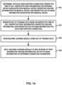
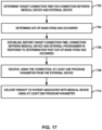
- System, umfassend:Telemetrieschaltung (208, 308), die für die Kommunikation zwischen einer medizinischen Vorrichtung (106) und einer mit der medizinischen Vorrichtung verbundenen externen Vorrichtung (104) konfiguriert ist; undVerarbeitungsschaltung (210, 310), die konfiguriert ist zum:Bestimmen von Verbindungsparametern für eine Verbindung zwischen der medizinischen Vorrichtung und der externen Vorrichtung basierend auf einem oder mehreren von der externen Vorrichtung erkannten ersten Informationen und/oder von der medizinischen Vorrichtung erkannten zweiten Informationen;Ausgeben einer Werbung für die Verbindung zwischen der medizinischen Vorrichtung und der externen Vorrichtung basierend auf den Verbindungsparametern;Herstellen der Verbindung zwischen der medizinischen Vorrichtung und der externen Vorrichtung gemäß der Werbung;Empfangen, unter Verwendung der Verbindung zwischen der medizinischen Vorrichtung und der externen Vorrichtung, mindestens eines Programmparameters von der externen Vorrichtung; undVerabreichen einer Therapie an einen Patienten, der mit der medizinischen Vorrichtung verbunden ist, unter Verwendung des mindestens einen Programmparameters.
- System nach Anspruch 1, wobei die Telemetrieschaltung dazu konfiguriert ist, um die ersten Informationen über eines oder mehrere von einer Scan-Anforderung, einer zuvor von der externen Vorrichtung ausgegebenen Werbung oder einer zuvor hergestellten Verbindung zu empfangen.
- System nach einem der Ansprüche 1 bis 2, wobei die ersten Informationen eines oder mehrere umfassen von:einem ersten Sensorsignal von einem oder mehreren aus einem Mikrofon, einer Kamera, einem Beschleunigungsmesser, einem optischen Sensor, einem Global Positioning System (GPS) oder einem Geofencing-Signal, das von der externen Vorrichtung erkannt wird;einem zweiten Sensorsignal, das von einer tragbaren Vorrichtung erkannt wird, die mit der externen Vorrichtung verbunden ist; Anwendungsinformationen von einer auf der externen Vorrichtung ausgeführten Anwendung;einem Sperrzustandssignal, das angibt, ob sich die externe Vorrichtung in einem entsperrten oder einem gesperrten Zustand befindet;einem Kalenderereignis, das auf der externen Vorrichtung auftritt;einer von der externen Vorrichtung empfangenen Remote-Anforderung;einer Herstellung einer Verbindung zwischen der externen Vorrichtung und einem Automobil;einem Benutzer, der unter Verwendung der externen Vorrichtung auf eine mit der medizinischen Vorrichtung verbundene Anwendung zugreift; odereinen In-Band-Sting, das unter Verwendung einer Telemetriefrequenz der Verbindung zwischen der medizinischen Vorrichtung und der externen Vorrichtung empfangen wird.
- System nach einem der Ansprüche 1 bis 3, wobei die ersten Informationen eines oder mehrere umfassen von:einer von der medizinischen Vorrichtung erkannten Sensorausgabe;von der medizinischen Vorrichtung erkannten Bewegungsinformationen;von der medizinischen Vorrichtung erkannten Haltungsinformationen und/oder Rauminformationen;von der medizinischen Vorrichtung erkannten Schlafinformationen;einem Adaptivnutzungsmodul, das auf der medizinischen Vorrichtung betrieben wird und dazu konfiguriert ist, um eine Werberate der Verbindungsparameter basierend auf Historieninformationen auszuwählen;einer Erkennung eines Magnetresonanztomographie(MRT)-Signals durch die medizinische Vorrichtung; odereinem Zustand einer Verbindung zwischen der medizinischen Vorrichtung und der externen Vorrichtung oder einer anderen Vorrichtung.
- System nach einem der Ansprüche 1 bis 4, wobei die Verarbeitungsschaltung dazu konfiguriert ist, um Verbindungsparameter für die Verbindung zwischen der medizinischen Vorrichtung und der externen Vorrichtung ferner basierend auf Out-of-Band-Informationen zu ermitteln, die mit der medizinischen Vorrichtung verbunden sind, wobei die Out-of-Band-Informationen eines oder mehrere umfassen von:Nicht-Telemetriefrequenz, die sich von einer für die Verbindung zwischen der medizinischen Vorrichtung und der externen Vorrichtung verwendeten Frequenz unterscheidet; odereinem Out-of-Band-Sting, das eines oder mehrere umfasst von: Erkennen von Ultraschall durch die medizinische Vorrichtung, Erkennen einer Telefonspulen-Induktionsvorrichtung durch die medizinische Vorrichtung, Erkennen eines Magnetfelds durch die medizinische Vorrichtung, Erkennen einer Vibration eines externen Programmiergeräts durch die medizinische Vorrichtung, Erkennen von Licht durch die medizinische Vorrichtung, Erkennen von Sprache durch die medizinische Vorrichtung oder ein Klopfen auf den Körper eines Patienten in Verbindung mit der medizinischen Vorrichtung.
- System nach einem der Ansprüche 1 bis 5, wobei die Verarbeitungsschaltung zum Bestimmen der Verbindungsparameter ferner dazu konfiguriert ist, um eine Werberate zum Senden von Werbung zum Herstellen der Verbindung zu bestimmen.
- System nach einem der Ansprüche 1 bis 5, wobei die Verarbeitungsschaltung zum Bestimmen der Verbindungsparameter ferner dazu konfiguriert ist, um eine durchschnittliche Zugriffshäufigkeit für eine Tageszeit zu bestimmen und die Verbindungsparameter basierend auf der durchschnittlichen Zugriffshäufigkeit für die Tageszeit auszuwählen.
- System nach Anspruch 7, wobei die Verarbeitungsschaltung zum Bestimmen der durchschnittlichen Zugriffshäufigkeit dazu konfiguriert ist, um eine Zeitleistenkarte der Benutzernutzung zu erzeugen.
- System nach einem der Ansprüche 1 bis 8,wobei die Verarbeitungsschaltung zum Bestimmen der Verbindungsparameter ferner dazu konfiguriert ist, um ein Maschinenlernmodul auf eine oder mehrere von den ersten Informationen oder den zweiten Informationen anzuwenden; undwobei das Maschinenlernmodul unter Verwendung eines Satzes von Trainingsdaten trainiert wurde, wobei der Satz von Trainingsdaten basierend auf einer jeweiligen Tageszeit, jeweiligen ersten Informationen und jeweiligen zweiten Informationen für jede vom Benutzer initiierte Verbindung aus einem Satz vorheriger vom Benutzer initiierter Verbindungen bestimmt wird.
- System nach Anspruch 9, wobei das externe Programmiergerät dazu konfiguriert ist, um:für jede vom Benutzer initiierte Verbindung aus dem Satz vorheriger Benutzerinteraktionen die jeweilige Tageszeit, die jeweiligen ersten Informationen für eine mit der medizinischen Vorrichtung verbundene externe Vorrichtung und die jeweiligen zweiten Informationen für die medizinische Vorrichtung zu bestimmen;den Satz von Trainingsdaten basierend auf der jeweiligen Tageszeit und den jeweiligen ersten Informationen, den jeweiligen zweiten Informationen für jede vom Benutzer initiierte Verbindung zu erzeugen; unddas Machinenlernmodul basierend auf dem Satz von Trainingsdaten zu trainieren.
- System nach einem der Ansprüche 1 bis 10, wobei die Verbindungsparameter ein energiearmes Bluetooth-Werbeintervall umfassen.
- System nach einem der Ansprüche 1 bis 11, wobei die externe Vorrichtung eine Mobilvorrichtung umfasst.
- System nach einem der Ansprüche 1 bis 12, wobei die medizinische Vorrichtung dazu konfiguriert ist, um die Verbindungsparameter zu bestimmen.
- System nach einem der Ansprüche 1 bis 13, wobei die medizinische Vorrichtung eine implantierbare medizinische Vorrichtung umfasst.
Applications Claiming Priority (2)
| Application Number | Priority Date | Filing Date | Title |
|---|---|---|---|
| US202163265977P | 2021-12-23 | 2021-12-23 | |
| US202263364007P | 2022-05-02 | 2022-05-02 |
Publications (3)
| Publication Number | Publication Date |
|---|---|
| EP4201473A1 EP4201473A1 (de) | 2023-06-28 |
| EP4201473C0 EP4201473C0 (de) | 2025-07-09 |
| EP4201473B1 true EP4201473B1 (de) | 2025-07-09 |
Family
ID=84541472
Family Applications (1)
| Application Number | Title | Priority Date | Filing Date |
|---|---|---|---|
| EP22214685.4A Active EP4201473B1 (de) | 2021-12-23 | 2022-12-19 | System zur energieverbrauchsreduzierung für konnektivität medizinischer vorrichtungen |
Country Status (2)
| Country | Link |
|---|---|
| US (3) | US12532246B2 (de) |
| EP (1) | EP4201473B1 (de) |
Families Citing this family (1)
| Publication number | Priority date | Publication date | Assignee | Title |
|---|---|---|---|---|
| CN121969421A (zh) * | 2023-09-29 | 2026-05-01 | 美敦力公司 | 调整医疗装置中的通告速率 |
Family Cites Families (15)
| Publication number | Priority date | Publication date | Assignee | Title |
|---|---|---|---|---|
| US8014867B2 (en) * | 2004-12-17 | 2011-09-06 | Cardiac Pacemakers, Inc. | MRI operation modes for implantable medical devices |
| EP2398553B1 (de) * | 2009-02-19 | 2015-07-22 | Cardiac Pacemakers, Inc. | Systeme zur bereitstellung einer therapie für arrhythmien in mrt-umgebungen |
| US9205268B2 (en) * | 2009-10-30 | 2015-12-08 | Medtronic, Inc. | Configuring operating parameters of a medical device based on a type of source of a disruptive energy field |
| EP2509682B1 (de) * | 2009-12-08 | 2015-01-14 | Cardiac Pacemakers, Inc. | Implantierbare medizinische vorrichtung mit automatischer erkennung und kontrolle von tachykardie in mri-umgebungen |
| US8929995B2 (en) * | 2010-10-29 | 2015-01-06 | Medtronic, Inc. | Implantable medical device telemetry in disruptive energy field |
| US9724520B2 (en) * | 2014-01-30 | 2017-08-08 | Medtronic, Inc. | Methods, implantable medical devices, and systems to continue implementing a special mode of operation after experiencing a device reset |
| US9445264B2 (en) | 2014-05-22 | 2016-09-13 | Pacesetter, Inc. | System and method for establishing a secured connection between an implantable medical device and an external device |
| US9288614B1 (en) | 2015-03-03 | 2016-03-15 | Pacesetter, Inc. | Systems and methods for initiating a communication link between an implantable medical device and an external device |
| US9913989B2 (en) * | 2016-04-28 | 2018-03-13 | Medtronic, Inc. | Managing telemetry communication modes of an implantable device |
| US9907486B2 (en) | 2016-05-20 | 2018-03-06 | Pacesetter, Inc. | Dynamic announcing for creation of wireless communication connections |
| US10517048B2 (en) | 2016-06-27 | 2019-12-24 | Avago Technologies International Sales Pte. Limited | Device and method for controlling a bluetooth low energy (BLE) advertiser |
| US9894691B1 (en) | 2016-08-10 | 2018-02-13 | Pacesetter, Inc. | Systems and methods for establishing a communication link between an implantable medical device and an external instrument |
| US11516860B2 (en) * | 2016-09-19 | 2022-11-29 | Pacesetter, Inc. | Implantable medical device and method for managing advertising and scanning schedules |
| US10182336B1 (en) | 2017-12-18 | 2019-01-15 | Pacesetter, Inc. | Low power advertisement schedule for implantable medical device and method |
| US11918819B2 (en) | 2018-10-31 | 2024-03-05 | Medtronic, Inc. | Facilitating acceleration of advertising rates for medical devices |
-
2022
- 2022-12-19 EP EP22214685.4A patent/EP4201473B1/de active Active
- 2022-12-21 US US18/069,346 patent/US12532246B2/en active Active
- 2022-12-21 US US18/069,606 patent/US12457547B2/en active Active
-
2025
- 2025-09-25 US US19/340,492 patent/US20260025739A1/en active Pending
Also Published As
| Publication number | Publication date |
|---|---|
| EP4201473A1 (de) | 2023-06-28 |
| EP4201473C0 (de) | 2025-07-09 |
| US12532246B2 (en) | 2026-01-20 |
| US20260025739A1 (en) | 2026-01-22 |
| US20230201575A1 (en) | 2023-06-29 |
| US12457547B2 (en) | 2025-10-28 |
| US20230209444A1 (en) | 2023-06-29 |
Similar Documents
| Publication | Publication Date | Title |
|---|---|---|
| US11318296B2 (en) | Signal-based automated deep brain stimulation programming | |
| US12036410B2 (en) | Multi-target adaptive neurostimulation therapy control | |
| US11135429B2 (en) | Neural oscillatory signal source location detection | |
| US20230062062A1 (en) | Detection of neural potential evoked in response to electrical stimulation | |
| EP4144405B1 (de) | Physiologische signalerfassung für eine stimulation mit geschlossenem regelkreis | |
| CN115697467A (zh) | 用于电刺激治疗的控制策略设置 | |
| US12502541B2 (en) | Device for assessment of brain signals | |
| US20260025739A1 (en) | Energy consumption reduction for medical device connectivity | |
| EP4395881B1 (de) | Nachweis eines als reaktion auf elektrische stimulation evozierten neuronalen potenzials | |
| US20230012100A1 (en) | Medication monitoring based on local field potential | |
| US12318617B2 (en) | Electrical stimulation therapy | |
| WO2024092079A1 (en) | Detecting neural state changes for deep brain stimulation (dbs) using evoked resonant neural activity (erna) | |
| US12533522B2 (en) | Telemetry connection for medical devices | |
| US20260131152A1 (en) | Telemetry connection for medical devices | |
| US12070605B2 (en) | Dynamically optimized neural sensing | |
| WO2025068821A1 (en) | Adjusting advertisement rates in medical devices | |
| WO2026024886A1 (en) | Environment awareness of telemetry noise conditions | |
| US20230347152A1 (en) | Closed-loop deep brain stimulation (dbs) programming based on evoked signals and local field potential (lfp) signals | |
| WO2026072828A1 (en) | Electrode-tissue interface stability determination | |
| WO2023215176A1 (en) | Closed-loop deep brain stimulation (dbs) programming based on evoked signals and local field potential (lfp) signals | |
| WO2025153877A1 (en) | Therapy scheduling for deep brain stimulation | |
| WO2026088151A1 (en) | Sensed signal strength for stimulation electrode selection | |
| WO2025046353A1 (en) | Sensing electrodes for monitoring events | |
| CN117897204A (zh) | 响应于电刺激而诱发的神经电位的检测 |
Legal Events
| Date | Code | Title | Description |
|---|---|---|---|
| PUAI | Public reference made under article 153(3) epc to a published international application that has entered the european phase |
Free format text: ORIGINAL CODE: 0009012 |
|
| STAA | Information on the status of an ep patent application or granted ep patent |
Free format text: STATUS: REQUEST FOR EXAMINATION WAS MADE |
|
| 17P | Request for examination filed |
Effective date: 20221219 |
|
| AK | Designated contracting states |
Kind code of ref document: A1 Designated state(s): AL AT BE BG CH CY CZ DE DK EE ES FI FR GB GR HR HU IE IS IT LI LT LU LV MC ME MK MT NL NO PL PT RO RS SE SI SK SM TR |
|
| STAA | Information on the status of an ep patent application or granted ep patent |
Free format text: STATUS: EXAMINATION IS IN PROGRESS |
|
| 17Q | First examination report despatched |
Effective date: 20240503 |
|
| GRAP | Despatch of communication of intention to grant a patent |
Free format text: ORIGINAL CODE: EPIDOSNIGR1 |
|
| STAA | Information on the status of an ep patent application or granted ep patent |
Free format text: STATUS: GRANT OF PATENT IS INTENDED |
|
| INTG | Intention to grant announced |
Effective date: 20250210 |
|
| GRAS | Grant fee paid |
Free format text: ORIGINAL CODE: EPIDOSNIGR3 |
|
| GRAA | (expected) grant |
Free format text: ORIGINAL CODE: 0009210 |
|
| STAA | Information on the status of an ep patent application or granted ep patent |
Free format text: STATUS: THE PATENT HAS BEEN GRANTED |
|
| AK | Designated contracting states |
Kind code of ref document: B1 Designated state(s): AL AT BE BG CH CY CZ DE DK EE ES FI FR GB GR HR HU IE IS IT LI LT LU LV MC ME MK MT NL NO PL PT RO RS SE SI SK SM TR |
|
| REG | Reference to a national code |
Ref country code: GB Ref legal event code: FG4D |
|
| REG | Reference to a national code |
Ref country code: CH Ref legal event code: EP |
|
| REG | Reference to a national code |
Ref country code: IE Ref legal event code: FG4D |
|
| REG | Reference to a national code |
Ref country code: DE Ref legal event code: R096 Ref document number: 602022017269 Country of ref document: DE |
|
| U01 | Request for unitary effect filed |
Effective date: 20250724 |
|
| U07 | Unitary effect registered |
Designated state(s): AT BE BG DE DK EE FI FR IT LT LU LV MT NL PT RO SE SI Effective date: 20250801 |
|
| U20 | Renewal fee for the european patent with unitary effect paid |
Year of fee payment: 4 Effective date: 20251119 |
|
| PG25 | Lapsed in a contracting state [announced via postgrant information from national office to epo] |
Ref country code: IS Free format text: LAPSE BECAUSE OF FAILURE TO SUBMIT A TRANSLATION OF THE DESCRIPTION OR TO PAY THE FEE WITHIN THE PRESCRIBED TIME-LIMIT Effective date: 20251109 |
|
| PG25 | Lapsed in a contracting state [announced via postgrant information from national office to epo] |
Ref country code: NO Free format text: LAPSE BECAUSE OF FAILURE TO SUBMIT A TRANSLATION OF THE DESCRIPTION OR TO PAY THE FEE WITHIN THE PRESCRIBED TIME-LIMIT Effective date: 20251009 |
|
| PG25 | Lapsed in a contracting state [announced via postgrant information from national office to epo] |
Ref country code: HR Free format text: LAPSE BECAUSE OF FAILURE TO SUBMIT A TRANSLATION OF THE DESCRIPTION OR TO PAY THE FEE WITHIN THE PRESCRIBED TIME-LIMIT Effective date: 20250709 |
|
| PG25 | Lapsed in a contracting state [announced via postgrant information from national office to epo] |
Ref country code: GR Free format text: LAPSE BECAUSE OF FAILURE TO SUBMIT A TRANSLATION OF THE DESCRIPTION OR TO PAY THE FEE WITHIN THE PRESCRIBED TIME-LIMIT Effective date: 20251010 |
|
| PG25 | Lapsed in a contracting state [announced via postgrant information from national office to epo] |
Ref country code: PL Free format text: LAPSE BECAUSE OF FAILURE TO SUBMIT A TRANSLATION OF THE DESCRIPTION OR TO PAY THE FEE WITHIN THE PRESCRIBED TIME-LIMIT Effective date: 20250709 |
|
| PG25 | Lapsed in a contracting state [announced via postgrant information from national office to epo] |
Ref country code: RS Free format text: LAPSE BECAUSE OF FAILURE TO SUBMIT A TRANSLATION OF THE DESCRIPTION OR TO PAY THE FEE WITHIN THE PRESCRIBED TIME-LIMIT Effective date: 20251009 |
|
| PG25 | Lapsed in a contracting state [announced via postgrant information from national office to epo] |
Ref country code: ES Free format text: LAPSE BECAUSE OF FAILURE TO SUBMIT A TRANSLATION OF THE DESCRIPTION OR TO PAY THE FEE WITHIN THE PRESCRIBED TIME-LIMIT Effective date: 20250709 |
|
| PG25 | Lapsed in a contracting state [announced via postgrant information from national office to epo] |
Ref country code: SM Free format text: LAPSE BECAUSE OF FAILURE TO SUBMIT A TRANSLATION OF THE DESCRIPTION OR TO PAY THE FEE WITHIN THE PRESCRIBED TIME-LIMIT Effective date: 20250709 |
|
| PG25 | Lapsed in a contracting state [announced via postgrant information from national office to epo] |
Ref country code: CZ Free format text: LAPSE BECAUSE OF FAILURE TO SUBMIT A TRANSLATION OF THE DESCRIPTION OR TO PAY THE FEE WITHIN THE PRESCRIBED TIME-LIMIT Effective date: 20250709 |
|
| PG25 | Lapsed in a contracting state [announced via postgrant information from national office to epo] |
Ref country code: SK Free format text: LAPSE BECAUSE OF FAILURE TO SUBMIT A TRANSLATION OF THE DESCRIPTION OR TO PAY THE FEE WITHIN THE PRESCRIBED TIME-LIMIT Effective date: 20250709 |
|
| PLBE | No opposition filed within time limit |
Free format text: ORIGINAL CODE: 0009261 |
|
| STAA | Information on the status of an ep patent application or granted ep patent |
Free format text: STATUS: NO OPPOSITION FILED WITHIN TIME LIMIT |