EP4201370A1 - Körperpflegevorrichtungen - Google Patents
Körperpflegevorrichtungen Download PDFInfo
- Publication number
- EP4201370A1 EP4201370A1 EP21217425.4A EP21217425A EP4201370A1 EP 4201370 A1 EP4201370 A1 EP 4201370A1 EP 21217425 A EP21217425 A EP 21217425A EP 4201370 A1 EP4201370 A1 EP 4201370A1
- Authority
- EP
- European Patent Office
- Prior art keywords
- image
- image data
- personal care
- captured
- care device
- Prior art date
- Legal status (The legal status is an assumption and is not a legal conclusion. Google has not performed a legal analysis and makes no representation as to the accuracy of the status listed.)
- Pending
Links
Images


Classifications
-
- A—HUMAN NECESSITIES
- A61—MEDICAL OR VETERINARY SCIENCE; HYGIENE
- A61C—DENTISTRY; APPARATUS OR METHODS FOR ORAL OR DENTAL HYGIENE
- A61C9/00—Impression cups, i.e. impression trays; Impression methods
- A61C9/004—Means or methods for taking digitized impressions
-
- A—HUMAN NECESSITIES
- A61—MEDICAL OR VETERINARY SCIENCE; HYGIENE
- A61C—DENTISTRY; APPARATUS OR METHODS FOR ORAL OR DENTAL HYGIENE
- A61C17/00—Devices for cleaning, polishing, rinsing or drying teeth, teeth cavities or prostheses; Saliva removers; Dental appliances for receiving spittle
- A61C17/16—Power-driven cleaning or polishing devices
- A61C17/22—Power-driven cleaning or polishing devices with brushes, cushions, cups, or the like
- A61C17/221—Control arrangements therefor
-
- A—HUMAN NECESSITIES
- A61—MEDICAL OR VETERINARY SCIENCE; HYGIENE
- A61C—DENTISTRY; APPARATUS OR METHODS FOR ORAL OR DENTAL HYGIENE
- A61C9/00—Impression cups, i.e. impression trays; Impression methods
- A61C9/004—Means or methods for taking digitized impressions
- A61C9/0046—Data acquisition means or methods
- A61C9/0053—Optical means or methods, e.g. scanning the teeth by a laser or light beam
Definitions
- the present invention relates to the field of personal care devices, and in particular to the field of personal care devices that capture digital impressions of one or more features of a user.
- IOS Intra-Oral Scanner
- projected light e.g. laser or structured light
- image sensor an image sensor
- 3D three-dimensional
- Data provided by IOS can therefore be useful for oral care, including the detection of common dental pathologies such as caries, tooth discoloration, misalignment.
- personal care devices such as electric brushing or shaving devices
- they may provide a suitable vehicle to regularly capture images of a user.
- cameras or imaging sensors into personal care devices, such as toothbrushes for example.
- a main usage characteristic of a personal care device may be its vibration or cyclical/periodic movement
- images acquired by a camera integrated with a personal care device are typically distorted and/or blurred by the movement/vibration of the device.
- image stabilization techniques are known for portable handheld devices (e.g. smart phone, digital photo cameras, etc.), such techniques are only designed and optimized for low frequency (e.g. ⁇ 10 Hz), erratic (e.g. non-periodic, random, etc.) user-induced motions. Because a personal care device (such as a toothbrush) typically moves or vibrates at a much higher periodic frequency (e.g. >20-300 Hz), there remains a need to stabilize the image capture process and/or make the image acquisition process robust to device movements/vibrations generated by a personal care device.
- a personal care device such as a toothbrush
- a much higher periodic frequency e.g. >20-300 Hz
- a method of processing captured images from a personal care device wherein the personal care device comprises: a camera configured, in use, to capture images of one or more features of a user; and vibratory means adapted to vibrate the personal care device so that, in use, the personal care device (and the camera) vibrates, and wherein the method comprises:
- Proposed concepts thus aim to provide schemes, solutions, concepts, designs, methods and systems pertaining to aiding and/or improving image acquisition from a vibratory personal care device having a camera the image of which is influenced by the device vibration.
- This may either be a camera fixed rigidly to the vibrating device which may then vibrate with the device.
- the camera sensor itself may be situated in a stationary part of a device (e.g. a brush handle) whilst the optical system of the device (like an optical fiber, the imaging lens of the optical system) are subject to the device vibrations.
- embodiments of the invention propose identifying image data captured during a target part (e.g. low velocity/motion part) of the vibration cycle based on an assessment of edge quality within the image.
- an image of improved quality may then be constructed.
- improved images e.g. images exhibiting less blur and/or distortion
- improved images may be constructed/generated. In this way, improved images may be obtained from a vibratory personal care device.
- image data acquisition may be adapted based on the vibration cycle. For instance, image data may be identified for extraction and use based on its edge quality, thus ensuring that only image data captured during a preferred or optimal part of the vibration cycle is used to generate a reconstruction image.
- embodiments propose to control the processing of image data from images captured by the camera of a personal care device, wherein the control is based on an edge quality value of the image data.
- images of improved quality may be generated.
- Embodiments may therefore facilitate stable and high-quality image acquisition during tooth brushing.
- Such embodiments may be particularly relevant to teledentistry propositions, for example, by enabling improved imaging of a user's tooth, gum, tongue, etc.
- images obtained by proposed embodiments may aid dental care treatments and/or decision making. Accordingly, embodiments may be used in relation to dental treatment selection so as support a dental care professional when selecting treatment for a subject.
- embodiments may facilitate image-based diagnostics, superior location sensing, therapy planning (e.g. orthodontics, aligners) and/or dental treatment monitoring.
- therapy planning e.g. orthodontics, aligners
- dental treatment monitoring e.g. dental treatment monitoring.
- embodiments may support improved dental care. Improved image-based dental care may therefore be provided by proposed concepts.
- Embodiments may, however, be applicable to other vibratory personal care devices, such as shavers, skin cleansing devices, and the like.
- Embodiments may therefore provide the advantage that decision making in selecting a care treatment can be improved through the use of images captured by a vibratory personal care device. For example, embodiments may enable a larger number of oral care treatment options to be available (e.g. through the provision of more and/or improved information about a subject's oral health).
- Some embodiments may, for example, further comprise the preceding steps of: preprocessing the captured image with an image quality assessment algorithm to determine in image quality value; and preventing processing of the captured image with the edge detection algorithm if the determined image quality value does not meet a predetermined quality requirement.
- a check that the captured image is of a minimum required quality e.g. in terms of blur, distortion, contract, or edge quality
- Unwarranted or unnecessary processing or resource usage may thus be avoided for low quality, for example. For instance, if the captured images comprises a line of image data with poor/low edge quality, and the one or more adjacent line are then also found to comprise image data with poor/low edge quality second, it may be determined that there is little to no reason to undertake further processing of the image.
- Another embodiment may further comprise obtaining, as a reference image, an image captured by the camera.
- the first predetermined requirement may then require that the edge quality value of the image data of the identified region is greater than an edge quality value of image data of a corresponding region of the reference image.
- a starting/initial image may be used for the purpose of reference or comparison.
- the edge quality of the image data of a region of the captured image may then be easily compared with that of a corresponding region of the reconstruction image.
- the result of the comparison then enables a determination to be made as to whether or not to extract (i.e. use) the image data of that region of the captured image.
- Relatively simple and straight-forward image data comparison techniques may therefore be employed by embodiments to control the use of image data from images captured by the camera.
- the first predetermined requirement may require that the edge quality value of the image data of the identified region is greater than a predetermined edge quality threshold value. Comparison with a single value (rather than that of another image) may thus be employed. Simple comparison techniques/algorithms may therefore be employed. Also, use of a single threshold value may support simple and easy alteration of the requirement.
- the step of generating the reconstruction image may comprise storing the extracted image data from the identified region in a corresponding region of the reconstruction image.
- some embodiments may comprise storing the extracted image data from the identified region in a corresponding region of the reference image.
- the reference image may be updated and/or refine with image data having an improved edge quality value.
- processing the captured image may comprise:
- the segment of the captured image may, for example, comprise a row or column of the captured image. That is, the image data of the captured image may be deconstructed into segments that correspond to one or more rows or columns. This may reduce a processing burden for example. It is, however, noted that segments may comprise other size, sections and/or shapes of image data of the captured image.
- a computer program comprising computer program code means which is adapted, when said computer program is run on a computer, to implement a method according to proposed embodiment.
- a computer system comprising: a computer program product according to proposed embodiment; and one or more processors adapted to perform a method according to a proposed concept by execution of the computer-readable program code of said computer program product.
- a system for processing captured images from a personal care device wherein the personal care device comprises: a camera configured, in use, to capture images of one or more features of a user; and vibratory means adapted to vibrate the personal care device so that, in use, the personal care device (and the camera) vibrates.
- the system comprises:
- Such a system may be provided as a standalone system for use with one or more personal care devices.
- a system according to an embodiment may be employed with a conventional vibratory personal care device to provided improved and/or extended functionality.
- a personal care device comprising:
- the personal care device may comprise a toothbrush, and may preferably comprise an electric toothbrush that is adapted to vibrate in use. In other embodiments, the personal care device may comprise a mouthpiece that is adapted to vibrate in use.
- One or more proposed concept(s) may therefore be employed in a range of different personal care devices. Embodiments may therefore have wide application in the field of personal care devices (and image capture and/or processing concepts for images captured by vibratory personal care devices).
- the invention proposes concepts for aiding and/or improving image acquisition from a vibratory personal care device having a camera which vibrates with the device.
- embodiments may provide a system, device and/or method which identifies image data captured during a target part (e.g. low velocity/motion part) of the vibration cycle based on edge quality value of the image data. Control of the extraction or further processing of image data from captured images may then be undertaken according to the identified image data. Through such control of the image data acquisition, improved images (e.g. images exhibiting less blur and/or distortion) may be obtained.
- the acquisition of image data may be adapted according to the vibration cycle of the vibrating personal care device (in use). More specifically, it has been realized that one or more parts of the vibration cycle may be better suited to image capture, for example due to exhibiting reduced motion/movement. It has further been realized that the timing(s) of such a part of the vibration cycle preferred (or optimal) for image capture may be determined based on an edge quality value of captured image data.
- Simple assessment of edge quality within captured images may thus be employed to determine preferred, optimal or target image data for use in generating a high quality image exhibiting reduced blur and/or distortion.
- embodiments propose to adapt image data acquisition to the vibration of the personal care device, so as to provide images of improved quality.
- Embodiments may therefore facilitate stable and high-quality image acquisition during tooth brushing. Such embodiments may be particularly relevant to teledentistry propositions, for example, by enabling improved imaging of a user's tooth, gum, tongue, etc. For instance, images obtained by proposed embodiments may aid dental care treatments and/or decision making. Accordingly, embodiments may be used in relation to dental treatment selection so as support a dental care professional when selecting treatment for a subject.
- the electric toothbrush 10 comprises vibratory means 12 (specifically, a motor) that is adapted, in use, to vibrate a brush head 14 of the electric toothbrush 10 (with a frequency of about 200Hz).
- vibratory means 12 specifically, a motor
- a brush head 14 of the electric toothbrush 10 with a frequency of about 200Hz.
- the electric toothbrush 10 also comprises a camera 16 (e.g. digital camera) that is adapted, in use, to capture images of one or more oral features of a user.
- a camera 16 e.g. digital camera
- the motor 12 is configured to cause the brush head 14 to repeatedly rotate clockwise then anti-clockwise by around 10°-25° from a rest position in a periodic manner. In this way, the brush head 14 and also the camera vibrates with a periodic vibration waveform.
- Figure 2 depicts a graph showing an exemplary variation in angle ⁇ (of displacement) and angular velocity of the brush head 14 over time as the brush head 14 vibrates.
- the variation in displacement angle ⁇ of the brush head 14 is depicted by the solid line, whereas the variation in angular velocity v of the brush head 14 is depicted by the dashed line.
- 'low speed' periods 20 i.e. time periods wherein the magnitude of angular velocity v of the brush head 14 is below a threshold value Vth. More specifically, it is seen that, when the magnitude of the displacement angle ⁇ reaches a maximum value, such that the gradient of displacement angle ⁇ variation changes polarity (i.e. when the solid line changes direction), the angular velocity v of the brush head 14 is near-zero. It is proposed that these low speed periods 20 provide the most appropriate opportunities for image capture using a camera that may have limited speed and exposure tuning capabilities. Accordingly, embodiments are based on the concept(s) that the timing of data acquisition may be adapted according to the vibration cycle of the brush head 14. That is, embodiments propose to adapt image acquisition to the vibration of the personal care device, so as to provide images of improved quality.
- the electric toothbrush 10 comprises a system 18 for processing captured images.
- the system comprises a processor arrangement 18A (that may be at least partially distributed across a cloud processing environment for example) that is configured to process a captured image from the camera with an edge detection algorithm to identify a region of the captured image comprising image data having an edge quality value meeting a first predetermined requirement.
- the system also comprises an image processor 18B that is to extract image data from the identified region of the captured image and to generate a reconstruction image comprising the extracted image data.
- the processor arrangement 18A obtains an initial reconstruction (e.g. a reference image or a previously captured images). The processor arrangement 18A then processes a segment of the captured image with the edge detection algorithm to determine an edge quality value of the image data of the segment. The processor arrangement 18A then compares the edge quality value of the image data of the segment with an edge quality value of image data of a corresponding region of the initial reconstruction image. Based on the comparison result, the processor arrangement 18A determines whether or not to identify the segment as a region of the captured image comprising image data having an edge quality value meeting the first predetermined requirement.
- an initial reconstruction e.g. a reference image or a previously captured images.
- the processor arrangement 18A then processes a segment of the captured image with the edge detection algorithm to determine an edge quality value of the image data of the segment.
- the processor arrangement 18A compares the edge quality value of the image data of the segment with an edge quality value of image data of a corresponding region of the initial reconstruction image. Based on the comparison result, the processor arrangement 18A determines whether or not
- the first predetermined requirement may be that the edge quality value of the image data of the identified region is greater than an edge quality value of image data of a corresponding region of the reference image. If the edge quality value of the image data of the identified region is greater than an edge quality value of image data of a corresponding region of the reference image, the processor arrangement 18A identifies the region as a region of the captured image that meets the first predetermined requirement. In such an instance, the processor arrangement 18A is configured to identify regions of captured images having a higher edge quality value than that of a corresponding region of the reference image. Due to the improved (i.e. higher) edge quality, these regions are inferred to contain image data captured during the low speed periods 20 in the vibration cycle.
- the image processor 18B is then adapted to extract image data from the identified region(s) of the captured image.
- the system 18 is thus adapted to favor or synchronize image data acquisition with the low speed periods 20, thereby reducing an amount of movement in the acquired image data (which may otherwise cause blurring and/or distortion in a captured image).
- the edge quality values of a captured image can be analyzed to determine, by comparison with the reconstruction image, a preferred, optimal or target region of image data for acquisition.
- edges can be detected using a known edge detection algorithms like a kernel array multiplication with defined "edge values” like Prewitt or Sobel filters (detailed below respectively).
- edge detection algorithms like a kernel array multiplication with defined "edge values” like Prewitt or Sobel filters (detailed below respectively).
- a histogram of the edges detected and taking the mean and standard deviation may be used for an edge quality indicator (i.e. edge quality value) for the proposed concept(s) of identifying image data captured during periods of low or no speed/velocity in the vibration cycle.
- edge quality indicator i.e. edge quality value
- the camera 16 of the embodiment of Figure 1 comprises an illumination device 19 (e.g. LED) that is configured, in use, to illuminate a part of the user's oral cavity.
- an illumination device 19 e.g. LED
- Figure 1 has been described as employing a brush head 14 that repeatedly rotates clockwise then anti-clockwise by around 10°-25° from a rest position in a periodic manner, it will be appreciated that other embodiments may employ a brush head that vibrates in a different manner.
- alternative embodiments may comprise a brush head that rotates or that shakes (left and right, or up and down) repeatedly, i.e. repeatedly displaces (laterally or vertically) in opposite directions from a rest position.
- Such embodiments will still exhibit a cyclical vibration pattern having variations in displacement and velocity over time that form periodic waveforms as depicted in Figure 2 , and thus have repeating 'low speed' periods that are identifiable (e.g. via segments of a captured image having higher luminance or contrast).
- the proposed concept(s) have been described above with reference to rotating / angular motion of the vibrating part of the personal care device, the proposed concept(s) may be employed in other vibratory personal care devices exhibiting repetitive vibratory motion.
- the embodiment of Figure 1 employs a concept of comparing edge quality values of a captured image with those of another image
- the processor arrangement 18A may compare the edge quality values of a captured image with a predetermined edge quality threshold value.
- This edge quality threshold value may be changed or adapted according to one or more preferences or needs (e.g. image quality requirements, processing speed/resources, etc.).
- the use of a threshold value may support avoidance of processing of segments which - although better than corresponding segments in the reconstruction image - still exhibit very low quality, for example a very low contrast,
- FIG. 3 there is shown a simplified schematic block diagram of a mouthpiece 40 according to another embodiment.
- the mouthpiece 40 is adapted to be inserted into a user's mouth and vibrate (in use) for oral cleaning purposes.
- the mouthpiece 40 comprises vibratory means 42 (specifically, an electric motor) that is adapted, in use, to cause the mouthpiece to vibrate with periodic vibration waveform (having a frequency in the range of 100Hz-500Hz).
- vibratory means 42 specifically, an electric motor
- periodic vibration waveform having a frequency in the range of 100Hz-500Hz.
- the mouthpiece 40 also comprises a camera 44 positioned in the tray of the mouthpiece whereby it vibrates with the mouthpiece and adapted, in use, to capture images of one or more oral features of the user.
- a flash LED 46 is also provided in the tray of the mouthpiece for illuminating the oral cavity of the user, in use.
- the camera 44 and LED 46 are configured to be controlled by a control unit (i.e. controller) 48 of the mouthpiece.
- a system 49 for processing captured images from the camera 44 is configured to identify a region of a captured image comprising image data having an edge quality value meeting a predetermined requirement.
- the system 50 is configured to extract image data from the identified region of the captured image, and to generate a reconstruction image comprising the extracted image data.
- the system 50 for processing captured images determines regions of captured images that comprise image data captured during a low velocity part of the vibration cycle (e.g. a period of 'low speed/velocity' of the mouthpiece 40, i.e. time period wherein the magnitude of velocity of the mouthpiece 40 is below a predetermined threshold value).
- the system 50 controls image data acquisition so that it processes image data that was captured during the target/preferred part of the vibration cycle (e.g. during periods of 'low speed/velocity' of the mouthpiece 40).
- the camera 44 comprises a rolling shutter camera configured to operate at an image capture frame rate.
- a rolling shutter camera trade-offs in operating characteristics may be required. For example, rolling shutter cameras may be more cost effective (e.g. cheaper) but may take longer for a full image capture depending on the acquisition settings and/or capabilities.
- Embodiments therefore propose extracting image data from a captured image that was captured during a preferred/target (e.g. low speed) period of the vibration cycle.
- the camera can be free running and out of synchronization with vibration of the personal care device (and thus the image data capture frequency). A full image may then be reconstructed from image data acquired from multiple difference frames of the rolling shutter camera.
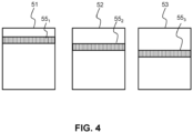
- Figure 4 provides an illustration of extracting image data from captured images according to a proposed embodiment.
- the illustration shows first 51, second 52 and third 53 sequentially-captured images from the rolling shutter camera 44 of Figure 3 (i.e. first to third sequential frames from the rolling shutter camera).
- the frames comprise first 55 1 second 55 2 and third 55 3 regions, which may e.g. be rows of pixels, which all correspond to the identical segment of the reconstruction image.
- reference to pixel may encompass a single sensing element of an image sensor or a sensing element (single sensor) of an image sensor array. That is, a pixel may be thought of as being a single element of a sensed image, wherein the sensed image is formed from a plurality of sensed elements (i.e. pixels).
- the first 55 1 second 55 2 and third 55 3 regions are in differing locations within the captured frames of rolling shutter camera. According to the proposed method, the image data of the second 55 2 region is compared with the first 55 1 region and subsequently the third 55 3 region is compared with the second 55 2 region.
- the first captured region may be captured in a relatively fast motion region where for example the edge quality is relatively low.
- the second captured region may be captured in a relatively low motion region where for example the edge quality is relatively high.
- the third captured region may be captured in a zero motion region where for example the edge quality is even higher than the second region.
- the image data of the second 55 2 region is extracted and replaces the first 55 1 region, and subsequently the third 55 3 regions is extracted and replaces the second 55 2 region, since, based on their edge quality values, they are identified as being captured during progressively superior, lower velocity period of the vibration cycle.
- embodiments may be configured to (indirectly) identify periods of low device velocity within the vibration cycle (through the identification of image data having a high edge quality). Image data captured during these identified periods may then be extracted and used to construct a single, reconstructed image of improved image quality. That is, by identifying regions of image data with high edge quality, embodiments may synchronize data extraction with the periods of low angular velocity.
- embodiments may be based on a realization that when low or no speed / motion is present, the edge quality is higher.
- a reconstruction time for a fully sharp image may be based on the number of sharp regions per captured image and thus have a direct relation to the camera motion, exposure time and capture speed. In an example, there may be 100 sharp lines per frame, where one frame consists of 640 lines. If the framerate of the camera is 30fps, a full image may be reconstructed from seven sequentially-captured images, resulting in a 7/30 second reconstruction time.
- FIG. 5 there is depicted a flow diagram of a method 600 of processing captured images from a personal care device according to a proposed embodiment.
- the personal care device comprises a vibratory means adapted to vibrate the personal care device so that, in use, the personal care device vibrates with a vibration cycle having a vibration.
- the personal care device also comprises a camera which vibrates with the device, adapted, in use, to capture images of one or more features of a user.
- the method 600 begins with the initialization 610 of a reconstruction image.
- the reconstruction image may be initialized with a first raw captured image from the camera (e.g. to enforce initial content).
- a captured image from the camera image is processed with an image processing algorithm to identify a region of the captured image comprising image data having an edge quality value meeting a predetermined requirement.
- the image processing algorithm compares the edge quality of each line of the captured image with that of a corresponding line of the reconstruction image. A line of the captured that has a better edge quality (i.e. has higher edge quality value) than the corresponding line of the reconstruction image is identified as a region meeting the requirement.
- image data is extracted from the identified regions in step 630.
- a new version of the reconstruction image is generated using the extracted data. Specifically, the extracted data is inserted into the corresponding regions/locations of the reconstruction image. In this way, data of the reconstruction image is replaced with sharp, blur-free image data captured during the 'still' (i.e. low velocity) moments in the vibration cycle, thus generating a new and improved version of the reconstruction image.
- the process of identifying 620 one or more regions, extracting 630 image data and generating 640 a new version of the reconstruction image can be repeated to generate new versions on the reconstruction image.
- the reconstruction image acts as a reference image.
- the requirement for a line of the captured image to have a better edge quality value may be made more stringent (i.e. more difficult for corresponding lines in subsequent captured image to exhibit a better edge quality).
- the reconstruction image may be continually improved and optimized to contain image data of the highest edge quality.
- Figure 6 illustrates an example of a computer 70 within which one or more parts of an embodiment may be employed.
- Various operations discussed above may utilize the capabilities of the computer 70.
- one or more parts of a system for providing a subject-specific user interface may be incorporated in any element, module, application, and/or component discussed herein.
- system functional blocks can run on a single computer or may be distributed over several computers and locations (e.g. connected via internet), such as a cloud-based computing infrastructure.
- the computer 70 includes, but is not limited to, PCs, workstations, laptops, PDAs, palm devices, servers, storages, and the like.
- the computer 70 may include one or more processors 71, memory 72, and one or more I/O devices 73 that are communicatively coupled via a local interface (not shown).
- the local interface can be, for example but not limited to, one or more buses or other wired or wireless connections, as is known in the art.
- the local interface may have additional elements, such as controllers, buffers (caches), drivers, repeaters, and receivers, to enable communications. Further, the local interface may include address, control, and/or data connections to enable appropriate communications among the aforementioned components.
- the processor 71 is a hardware device for executing software that can be stored in the memory 72.
- the processor 71 can be virtually any custom made or commercially available processor, a central processing unit (CPU), a digital signal processor (DSP), or an auxiliary processor among several processors associated with the computer 70, and the processor 71 may be a semiconductor based microprocessor (in the form of a microchip) or a microprocessor.
- the memory 72 can include any one or combination of volatile memory elements (e.g., random access memory (RAM), such as dynamic random access memory (DRAM), static random access memory (SRAM), etc.) and non-volatile memory elements (e.g., ROM, erasable programmable read only memory (EPROM), electronically erasable programmable read only memory (EEPROM), programmable read only memory (PROM), tape, compact disc read only memory (CD-ROM), disk, diskette, cartridge, cassette or the like, etc.).
- RAM random access memory
- DRAM dynamic random access memory
- SRAM static random access memory
- non-volatile memory elements e.g., ROM, erasable programmable read only memory (EPROM), electronically erasable programmable read only memory (EEPROM), programmable read only memory (PROM), tape, compact disc read only memory (CD-ROM), disk, diskette, cartridge, cassette or the like, etc.
- the memory 72 may incorporate electronic, magnetic, optical, and/or other types of storage
- the software in the memory 72 may include one or more separate programs, each of which comprises an ordered listing of executable instructions for implementing logical functions.
- the software in the memory 72 includes a suitable operating system (O/S) 74, compiler 76, source code 75, and one or more applications 77 in accordance with exemplary embodiments.
- the application 77 comprises numerous functional components for implementing the features and operations of the exemplary embodiments.
- the application 77 of the computer 70 may represent various applications, computational units, logic, functional units, processes, operations, virtual entities, and/or modules in accordance with exemplary embodiments, but the application 77 is not meant to be a limitation.
- the operating system 74 controls the execution of other computer programs, and provides scheduling, input-output control, file and data management, memory management, and communication control and related services. It is contemplated by the inventors that the application 77 for implementing exemplary embodiments may be applicable on all commercially available operating systems.
- Application 77 may be a source program, executable program (object code), script, or any other entity comprising a set of instructions to be performed.
- a source program then the program is usually translated via a compiler (such as the compiler 76), assembler, interpreter, or the like, which may or may not be included within the memory 72, so as to operate properly in connection with the O/S 74.
- the application 77 can be written as an object oriented programming language, which has classes of data and methods, or a procedure programming language, which has routines, subroutines, and/or functions, for example but not limited to, C, C++, C#, Pascal, BASIC, API calls, HTML, XHTML, XML, ASP scripts, JavaScript, FORTRAN, COBOL, Perl, Java, ADA, .NET, and the like.
- the I/O devices 73 may include input devices such as, for example but not limited to, a mouse, keyboard, scanner, microphone, camera, etc. Furthermore, the I/O devices 73 may also include output devices, for example but not limited to a printer, display, etc. Finally, the I/O devices 73 may further include devices that communicate both inputs and outputs, for instance but not limited to, a NIC or modulator/demodulator (for accessing remote devices, other files, devices, systems, or a network), a radio frequency (RF) or other transceiver, a telephonic interface, a bridge, a router, etc. The I/O devices 73 also include components for communicating over various networks, such as the Internet or intranet.
- a NIC or modulator/demodulator for accessing remote devices, other files, devices, systems, or a network
- RF radio frequency
- the I/O devices 73 also include components for communicating over various networks, such as the Internet or intranet.
- the software in the memory 72 may further include a basic input output system (BIOS) (omitted for simplicity).
- BIOS is a set of essential software routines that initialize and test hardware at startup, start the O/S 74, and support the transfer of data among the hardware devices.
- the BIOS is stored in some type of read-only-memory, such as ROM, PROM, EPROM, EEPROM or the like, so that the BIOS can be executed when the computer 70 is activated.
- the processor 71 When the computer 70 is in operation, the processor 71 is configured to execute software stored within the memory 72, to communicate data to and from the memory 72, and to generally control operations of the computer 70 pursuant to the software.
- the application 77 and the O/S 74 are read, in whole or in part, by the processor 71, perhaps buffered within the processor 71, and then executed.
- a computer readable medium may be an electronic, magnetic, optical, or other physical device or means that can contain or store a computer program for use by or in connection with a computer related system or method.
- the application 77 can be embodied in any computer-readable medium for use by or in connection with an instruction execution system, apparatus, or device, such as a computer-based system, processor-containing system, or other system that can fetch the instructions from the instruction execution system, apparatus, or device and execute the instructions.
- a "computer-readable medium" can be any means that can store, communicate, propagate, or transport the program for use by or in connection with the instruction execution system, apparatus, or device.
- the computer readable medium can be, for example but not limited to, an electronic, magnetic, optical, electromagnetic, infrared, or semiconductor system, apparatus, device, or propagation medium.
- the proposed image capture and/or processing methods may be implemented in hardware or software, or a mixture of both (for example, as firmware running on a hardware device).
- the functional steps illustrated in the process flowcharts may be performed by suitably programmed physical computing devices, such as one or more central processing units (CPUs) or graphics processing units (GPUs).
- CPUs central processing units
- GPUs graphics processing units
- Each process - and its individual component steps as illustrated in the flowcharts - may be performed by the same or different computing devices.
- a computer-readable storage medium stores a computer program comprising computer program code configured to cause one or more physical computing devices to carry out an encoding or decoding method as described above when the program is run on the one or more physical computing devices.
- Storage media may include volatile and non-volatile computer memory such as RAM, PROM, EPROM, and EEPROM, optical discs (like CD, DVD, BD), magnetic storage media (like hard discs and tapes).
- RAM random access memory
- PROM read-only memory
- EPROM erasable programmable read-only memory
- EEPROM electrically erasable programmable read-only memory
- optical discs like CD, DVD, BD
- magnetic storage media like hard discs and tapes.
- Various storage media may be fixed within a computing device or may be transportable, such that the one or more programs stored thereon can be loaded into a processor.
- the blocks shown in the block diagrams of Figs. 1 and 3 may be separate physical components, or logical subdivisions of single physical components, or may be all implemented in an integrated manner in one physical component.
- the functions of one block shown in the drawings may be divided between multiple components in an implementation, or the functions of multiple blocks shown in the drawings may be combined in single components in an implementation.
- Hardware components suitable for use in embodiments of the present invention include, but are not limited to, conventional microprocessors, application specific integrated circuits (ASICs), and field-programmable gate arrays (FPGAs).
- ASICs application specific integrated circuits
- FPGAs field-programmable gate arrays
- One or more blocks may be implemented as a combination of dedicated hardware to perform some functions and one or more programmed microprocessors and associated circuitry to perform other functions.
- a computer program may be stored/distributed on a suitable medium, such as an optical storage medium or a solid-state medium supplied together with or as part of other hardware, but may also be distributed in other forms, such as via the Internet or other wired or wireless telecommunication systems.
- a suitable medium such as an optical storage medium or a solid-state medium supplied together with or as part of other hardware, but may also be distributed in other forms, such as via the Internet or other wired or wireless telecommunication systems.
- each block in the flowchart or block diagrams may represent a module, segment, or portion of instructions, which comprises one or more executable instructions for implementing the specified logical function(s).
- the functions noted in the block may occur out of the order noted in the figures.
- two blocks shown in succession may, in fact, be executed substantially concurrently, or the blocks may sometimes be executed in the reverse order, depending upon the functionality involved.
Priority Applications (2)
| Application Number | Priority Date | Filing Date | Title |
|---|---|---|---|
| EP21217425.4A EP4201370A1 (de) | 2021-12-23 | 2021-12-23 | Körperpflegevorrichtungen |
| PCT/EP2022/084883 WO2023117437A1 (en) | 2021-12-23 | 2022-12-08 | Personal care devices |
Applications Claiming Priority (1)
| Application Number | Priority Date | Filing Date | Title |
|---|---|---|---|
| EP21217425.4A EP4201370A1 (de) | 2021-12-23 | 2021-12-23 | Körperpflegevorrichtungen |
Publications (1)
| Publication Number | Publication Date |
|---|---|
| EP4201370A1 true EP4201370A1 (de) | 2023-06-28 |
Family
ID=79164449
Family Applications (1)
| Application Number | Title | Priority Date | Filing Date |
|---|---|---|---|
| EP21217425.4A Pending EP4201370A1 (de) | 2021-12-23 | 2021-12-23 | Körperpflegevorrichtungen |
Country Status (2)
| Country | Link |
|---|---|
| EP (1) | EP4201370A1 (de) |
| WO (1) | WO2023117437A1 (de) |
Citations (3)
| Publication number | Priority date | Publication date | Assignee | Title |
|---|---|---|---|---|
| US20180125610A1 (en) * | 2016-11-04 | 2018-05-10 | Align Technology, Inc. | Methods and apparatuses for dental images |
| US20210019885A1 (en) * | 2018-04-02 | 2021-01-21 | Koninklijke Philips N.V. | Method and system for teledentistry images |
| US20210158607A1 (en) * | 2019-11-26 | 2021-05-27 | Sdc U.S. Smilepay Spv | Systems and methods for constructing a three-dimensional model from two-dimensional images |
-
2021
- 2021-12-23 EP EP21217425.4A patent/EP4201370A1/de active Pending
-
2022
- 2022-12-08 WO PCT/EP2022/084883 patent/WO2023117437A1/en unknown
Patent Citations (3)
| Publication number | Priority date | Publication date | Assignee | Title |
|---|---|---|---|---|
| US20180125610A1 (en) * | 2016-11-04 | 2018-05-10 | Align Technology, Inc. | Methods and apparatuses for dental images |
| US20210019885A1 (en) * | 2018-04-02 | 2021-01-21 | Koninklijke Philips N.V. | Method and system for teledentistry images |
| US20210158607A1 (en) * | 2019-11-26 | 2021-05-27 | Sdc U.S. Smilepay Spv | Systems and methods for constructing a three-dimensional model from two-dimensional images |
Also Published As
| Publication number | Publication date |
|---|---|
| WO2023117437A1 (en) | 2023-06-29 |
Similar Documents
| Publication | Publication Date | Title |
|---|---|---|
| CN109068058B (zh) | 超级夜景模式下的拍摄控制方法、装置和电子设备 | |
| US10129477B2 (en) | Smart image sensor having integrated memory and processor | |
| JP2011529649A5 (de) | ||
| WO2019015477A1 (zh) | 图像矫正方法、计算机可读存储介质和计算机设备 | |
| WO2023141533A1 (en) | Photo-based dental appliance and attachment assessment | |
| CN109690611A (zh) | 一种图像校正方法及装置 | |
| JP2013138413A (ja) | 撮像装置 | |
| EP4201370A1 (de) | Körperpflegevorrichtungen | |
| US20220378548A1 (en) | Method for generating a dental image | |
| EP4203452A1 (de) | Körperpflegevorrichtungen | |
| US20210011551A1 (en) | Method, Eyetracker and Computer Program for Determining Eye Positions in Digital Image Data | |
| EP4201371A1 (de) | Körperpflegevorrichtungen | |
| EP4201373A1 (de) | Körperpflegevorrichtungen | |
| EP4201374A1 (de) | Körperpflegevorrichtung | |
| JP4926450B2 (ja) | 画像処理装置 | |
| EP4203453A1 (de) | Körperpflegevorrichtungen | |
| EP4201375A1 (de) | Körperpflegevorrichtung | |
| JP7110899B2 (ja) | 画像処理装置、画像処理方法、及び画像処理プログラム | |
| JP2021047827A (ja) | デバイス、システム、制御方法、及びプログラム | |
| JP6521612B2 (ja) | 撮像装置、撮像方法、撮像プログラム、画像処理装置、画像処理方法および画像処理プログラム | |
| JP2003230045A (ja) | 信号処理方法および装置 | |
| CN117414110B (zh) | 三维扫描设备的控制方法、装置、终端设备及系统 | |
| JP2007116332A (ja) | 画像処理装置 | |
| WO2022208606A1 (ja) | 学習システム、認証システム、学習方法、コンピュータプログラム、学習モデル生成装置、及び推定装置 | |
| US9298319B2 (en) | Multi-touch recognition apparatus using filtering and a difference image and control method thereof |
Legal Events
| Date | Code | Title | Description |
|---|---|---|---|
| PUAI | Public reference made under article 153(3) epc to a published international application that has entered the european phase |
Free format text: ORIGINAL CODE: 0009012 |
|
| STAA | Information on the status of an ep patent application or granted ep patent |
Free format text: STATUS: THE APPLICATION HAS BEEN PUBLISHED |
|
| AK | Designated contracting states |
Kind code of ref document: A1 Designated state(s): AL AT BE BG CH CY CZ DE DK EE ES FI FR GB GR HR HU IE IS IT LI LT LU LV MC MK MT NL NO PL PT RO RS SE SI SK SM TR |