EP4201252A1 - Applicator - Google Patents
Applicator Download PDFInfo
- Publication number
- EP4201252A1 EP4201252A1 EP21858386.2A EP21858386A EP4201252A1 EP 4201252 A1 EP4201252 A1 EP 4201252A1 EP 21858386 A EP21858386 A EP 21858386A EP 4201252 A1 EP4201252 A1 EP 4201252A1
- Authority
- EP
- European Patent Office
- Prior art keywords
- barrel
- front barrel
- cap
- threaded portion
- applicator
- Prior art date
- Legal status (The legal status is an assumption and is not a legal conclusion. Google has not performed a legal analysis and makes no representation as to the accuracy of the status listed.)
- Pending
Links
- 239000007788 liquid Substances 0.000 claims abstract description 80
- 239000002537 cosmetic Substances 0.000 claims abstract description 41
- 230000002093 peripheral effect Effects 0.000 claims abstract description 34
- 238000010586 diagram Methods 0.000 description 13
- 239000000463 material Substances 0.000 description 9
- XLYOFNOQVPJJNP-UHFFFAOYSA-N water Substances O XLYOFNOQVPJJNP-UHFFFAOYSA-N 0.000 description 8
- UQSXHKLRYXJYBZ-UHFFFAOYSA-N Iron oxide Chemical compound [Fe]=O UQSXHKLRYXJYBZ-UHFFFAOYSA-N 0.000 description 6
- 239000011248 coating agent Substances 0.000 description 6
- 238000000576 coating method Methods 0.000 description 6
- 238000004040 coloring Methods 0.000 description 6
- 239000002245 particle Substances 0.000 description 6
- 230000000694 effects Effects 0.000 description 5
- 239000003795 chemical substances by application Substances 0.000 description 4
- 239000011347 resin Substances 0.000 description 4
- 229920005989 resin Polymers 0.000 description 4
- SGHZXLIDFTYFHQ-UHFFFAOYSA-L Brilliant Blue Chemical compound [Na+].[Na+].C=1C=C(C(=C2C=CC(C=C2)=[N+](CC)CC=2C=C(C=CC=2)S([O-])(=O)=O)C=2C(=CC=CC=2)S([O-])(=O)=O)C=CC=1N(CC)CC1=CC=CC(S([O-])(=O)=O)=C1 SGHZXLIDFTYFHQ-UHFFFAOYSA-L 0.000 description 3
- GWEVSGVZZGPLCZ-UHFFFAOYSA-N Titan oxide Chemical compound O=[Ti]=O GWEVSGVZZGPLCZ-UHFFFAOYSA-N 0.000 description 3
- IRERQBUNZFJFGC-UHFFFAOYSA-L azure blue Chemical compound [Na+].[Na+].[Na+].[Na+].[Na+].[Na+].[Na+].[Na+].[Al+3].[Al+3].[Al+3].[Al+3].[Al+3].[Al+3].[S-]S[S-].[O-][Si]([O-])([O-])[O-].[O-][Si]([O-])([O-])[O-].[O-][Si]([O-])([O-])[O-].[O-][Si]([O-])([O-])[O-].[O-][Si]([O-])([O-])[O-].[O-][Si]([O-])([O-])[O-] IRERQBUNZFJFGC-UHFFFAOYSA-L 0.000 description 3
- DCYOBGZUOMKFPA-UHFFFAOYSA-N iron(2+);iron(3+);octadecacyanide Chemical compound [Fe+2].[Fe+2].[Fe+2].[Fe+3].[Fe+3].[Fe+3].[Fe+3].N#[C-].N#[C-].N#[C-].N#[C-].N#[C-].N#[C-].N#[C-].N#[C-].N#[C-].N#[C-].N#[C-].N#[C-].N#[C-].N#[C-].N#[C-].N#[C-].N#[C-].N#[C-] DCYOBGZUOMKFPA-UHFFFAOYSA-N 0.000 description 3
- 239000003960 organic solvent Substances 0.000 description 3
- 229960003351 prussian blue Drugs 0.000 description 3
- 239000013225 prussian blue Substances 0.000 description 3
- OGIDPMRJRNCKJF-UHFFFAOYSA-N titanium oxide Inorganic materials [Ti]=O OGIDPMRJRNCKJF-UHFFFAOYSA-N 0.000 description 3
- 238000009423 ventilation Methods 0.000 description 3
- LFQSCWFLJHTTHZ-UHFFFAOYSA-N Ethanol Chemical compound CCO LFQSCWFLJHTTHZ-UHFFFAOYSA-N 0.000 description 2
- KFZMGEQAYNKOFK-UHFFFAOYSA-N Isopropanol Chemical compound CC(C)O KFZMGEQAYNKOFK-UHFFFAOYSA-N 0.000 description 2
- PPBRXRYQALVLMV-UHFFFAOYSA-N Styrene Chemical compound C=CC1=CC=CC=C1 PPBRXRYQALVLMV-UHFFFAOYSA-N 0.000 description 2
- CQPFMGBJSMSXLP-UHFFFAOYSA-M acid orange 7 Chemical compound [Na+].OC1=CC=C2C=CC=CC2=C1N=NC1=CC=C(S([O-])(=O)=O)C=C1 CQPFMGBJSMSXLP-UHFFFAOYSA-M 0.000 description 2
- 235000012745 brilliant blue FCF Nutrition 0.000 description 2
- 239000004161 brilliant blue FCF Substances 0.000 description 2
- CEZCCHQBSQPRMU-UHFFFAOYSA-L chembl174821 Chemical compound [Na+].[Na+].COC1=CC(S([O-])(=O)=O)=C(C)C=C1N=NC1=C(O)C=CC2=CC(S([O-])(=O)=O)=CC=C12 CEZCCHQBSQPRMU-UHFFFAOYSA-L 0.000 description 2
- 238000013461 design Methods 0.000 description 2
- LQJVOKWHGUAUHK-UHFFFAOYSA-L disodium 5-amino-4-hydroxy-3-phenyldiazenylnaphthalene-2,7-disulfonate Chemical compound [Na+].[Na+].OC1=C2C(N)=CC(S([O-])(=O)=O)=CC2=CC(S([O-])(=O)=O)=C1N=NC1=CC=CC=C1 LQJVOKWHGUAUHK-UHFFFAOYSA-L 0.000 description 2
- 239000000839 emulsion Substances 0.000 description 2
- SEACYXSIPDVVMV-UHFFFAOYSA-L eosin Y Chemical compound [Na+].[Na+].[O-]C(=O)C1=CC=CC=C1C1=C2C=C(Br)C(=O)C(Br)=C2OC2=C(Br)C([O-])=C(Br)C=C21 SEACYXSIPDVVMV-UHFFFAOYSA-L 0.000 description 2
- 235000012732 erythrosine Nutrition 0.000 description 2
- 239000000835 fiber Substances 0.000 description 2
- 239000004615 ingredient Substances 0.000 description 2
- 230000013011 mating Effects 0.000 description 2
- 238000000034 method Methods 0.000 description 2
- 238000003756 stirring Methods 0.000 description 2
- UJMBCXLDXJUMFB-UHFFFAOYSA-K trisodium;5-oxo-1-(4-sulfonatophenyl)-4-[(4-sulfonatophenyl)diazenyl]-4h-pyrazole-3-carboxylate Chemical compound [Na+].[Na+].[Na+].[O-]C(=O)C1=NN(C=2C=CC(=CC=2)S([O-])(=O)=O)C(=O)C1N=NC1=CC=C(S([O-])(=O)=O)C=C1 UJMBCXLDXJUMFB-UHFFFAOYSA-K 0.000 description 2
- XLTMWFMRJZDFFD-UHFFFAOYSA-N 1-[(2-chloro-4-nitrophenyl)diazenyl]naphthalen-2-ol Chemical compound OC1=CC=C2C=CC=CC2=C1N=NC1=CC=C([N+]([O-])=O)C=C1Cl XLTMWFMRJZDFFD-UHFFFAOYSA-N 0.000 description 1
- SMZOUWXMTYCWNB-UHFFFAOYSA-N 2-(2-methoxy-5-methylphenyl)ethanamine Chemical compound COC1=CC=C(C)C=C1CCN SMZOUWXMTYCWNB-UHFFFAOYSA-N 0.000 description 1
- NIXOWILDQLNWCW-UHFFFAOYSA-N 2-Propenoic acid Natural products OC(=O)C=C NIXOWILDQLNWCW-UHFFFAOYSA-N 0.000 description 1
- GNCOVOVCHIHPHP-UHFFFAOYSA-N 2-[[4-[4-[(1-anilino-1,3-dioxobutan-2-yl)diazenyl]-3-chlorophenyl]-2-chlorophenyl]diazenyl]-3-oxo-n-phenylbutanamide Chemical compound C=1C=CC=CC=1NC(=O)C(C(=O)C)N=NC(C(=C1)Cl)=CC=C1C(C=C1Cl)=CC=C1N=NC(C(C)=O)C(=O)NC1=CC=CC=C1 GNCOVOVCHIHPHP-UHFFFAOYSA-N 0.000 description 1
- UBVSIAHUTXHQTD-UHFFFAOYSA-N 2-n-(4-bromophenyl)-1,3,5-triazine-2,4-diamine Chemical compound NC1=NC=NC(NC=2C=CC(Br)=CC=2)=N1 UBVSIAHUTXHQTD-UHFFFAOYSA-N 0.000 description 1
- QCDWFXQBSFUVSP-UHFFFAOYSA-N 2-phenoxyethanol Chemical compound OCCOC1=CC=CC=C1 QCDWFXQBSFUVSP-UHFFFAOYSA-N 0.000 description 1
- WLDHEUZGFKACJH-ZRUFZDNISA-K Amaranth Chemical compound [Na+].[Na+].[Na+].C12=CC=C(S([O-])(=O)=O)C=C2C=C(S([O-])(=O)=O)C(O)=C1\N=N\C1=CC=C(S([O-])(=O)=O)C2=CC=CC=C12 WLDHEUZGFKACJH-ZRUFZDNISA-K 0.000 description 1
- RZSYLLSAWYUBPE-UHFFFAOYSA-L Fast green FCF Chemical compound [Na+].[Na+].C=1C=C(C(=C2C=CC(C=C2)=[N+](CC)CC=2C=C(C=CC=2)S([O-])(=O)=O)C=2C(=CC(O)=CC=2)S([O-])(=O)=O)C=CC=1N(CC)CC1=CC=CC(S([O-])(=O)=O)=C1 RZSYLLSAWYUBPE-UHFFFAOYSA-L 0.000 description 1
- -1 Green No. 402 Chemical compound 0.000 description 1
- QQILFGKZUJYXGS-UHFFFAOYSA-N Indigo dye Chemical compound C1=CC=C2C(=O)C(C3=C(C4=CC=CC=C4N3)O)=NC2=C1 QQILFGKZUJYXGS-UHFFFAOYSA-N 0.000 description 1
- CERQOIWHTDAKMF-UHFFFAOYSA-N Methacrylic acid Chemical compound CC(=C)C(O)=O CERQOIWHTDAKMF-UHFFFAOYSA-N 0.000 description 1
- SJEYSFABYSGQBG-UHFFFAOYSA-M Patent blue Chemical compound [Na+].C1=CC(N(CC)CC)=CC=C1C(C=1C(=CC(=CC=1)S([O-])(=O)=O)S([O-])(=O)=O)=C1C=CC(=[N+](CC)CC)C=C1 SJEYSFABYSGQBG-UHFFFAOYSA-M 0.000 description 1
- XTXRWKRVRITETP-UHFFFAOYSA-N Vinyl acetate Chemical compound CC(=O)OC=C XTXRWKRVRITETP-UHFFFAOYSA-N 0.000 description 1
- 239000006096 absorbing agent Substances 0.000 description 1
- 239000000980 acid dye Substances 0.000 description 1
- 229940099540 acid violet 43 Drugs 0.000 description 1
- 125000005907 alkyl ester group Chemical group 0.000 description 1
- 230000002421 anti-septic effect Effects 0.000 description 1
- 239000003963 antioxidant agent Substances 0.000 description 1
- 230000003796 beauty Effects 0.000 description 1
- 238000007664 blowing Methods 0.000 description 1
- 239000006229 carbon black Substances 0.000 description 1
- 235000012730 carminic acid Nutrition 0.000 description 1
- 239000002738 chelating agent Substances 0.000 description 1
- OIQPTROHQCGFEF-UHFFFAOYSA-L chembl1371409 Chemical compound [Na+].[Na+].OC1=CC=C2C=C(S([O-])(=O)=O)C=CC2=C1N=NC1=CC=C(S([O-])(=O)=O)C=C1 OIQPTROHQCGFEF-UHFFFAOYSA-L 0.000 description 1
- PZTQVMXMKVTIRC-UHFFFAOYSA-L chembl2028348 Chemical compound [Ca+2].[O-]S(=O)(=O)C1=CC(C)=CC=C1N=NC1=C(O)C(C([O-])=O)=CC2=CC=CC=C12 PZTQVMXMKVTIRC-UHFFFAOYSA-L 0.000 description 1
- ONTQJDKFANPPKK-UHFFFAOYSA-L chembl3185981 Chemical compound [Na+].[Na+].CC1=CC(C)=C(S([O-])(=O)=O)C=C1N=NC1=CC(S([O-])(=O)=O)=C(C=CC=C2)C2=C1O ONTQJDKFANPPKK-UHFFFAOYSA-L 0.000 description 1
- 239000003086 colorant Substances 0.000 description 1
- 229920001577 copolymer Polymers 0.000 description 1
- 229940099441 d&c blue no. 4 Drugs 0.000 description 1
- 229940106008 d&c brown no. 1 Drugs 0.000 description 1
- 229940099449 d&c orange no. 4 Drugs 0.000 description 1
- 229940056316 d&c red no. 28 Drugs 0.000 description 1
- 229940075493 d&c red no. 6 Drugs 0.000 description 1
- 229940057946 d&c red no. 7 Drugs 0.000 description 1
- 238000011161 development Methods 0.000 description 1
- TVCBMJCHKADLEE-UHFFFAOYSA-N diazanium;2-[[4-[ethyl-[(4-sulfonatophenyl)methyl]amino]phenyl]-[4-[ethyl-[(4-sulfonatophenyl)methyl]azaniumylidene]cyclohexa-2,5-dien-1-ylidene]methyl]benzenesulfonate Chemical compound [NH4+].[NH4+].C=1C=C(C(=C2C=CC(C=C2)=[N+](CC)CC=2C=CC(=CC=2)S([O-])(=O)=O)C=2C(=CC=CC=2)S([O-])(=O)=O)C=CC=1N(CC)CC1=CC=C(S([O-])(=O)=O)C=C1 TVCBMJCHKADLEE-UHFFFAOYSA-N 0.000 description 1
- VPWFPZBFBFHIIL-UHFFFAOYSA-L disodium 4-[(4-methyl-2-sulfophenyl)diazenyl]-3-oxidonaphthalene-2-carboxylate Chemical compound [Na+].[Na+].[O-]S(=O)(=O)C1=CC(C)=CC=C1N=NC1=C(O)C(C([O-])=O)=CC2=CC=CC=C12 VPWFPZBFBFHIIL-UHFFFAOYSA-L 0.000 description 1
- FPAYXBWMYIMERV-UHFFFAOYSA-L disodium;5-methyl-2-[[4-(4-methyl-2-sulfonatoanilino)-9,10-dioxoanthracen-1-yl]amino]benzenesulfonate Chemical compound [Na+].[Na+].[O-]S(=O)(=O)C1=CC(C)=CC=C1NC(C=1C(=O)C2=CC=CC=C2C(=O)C=11)=CC=C1NC1=CC=C(C)C=C1S([O-])(=O)=O FPAYXBWMYIMERV-UHFFFAOYSA-L 0.000 description 1
- 239000012153 distilled water Substances 0.000 description 1
- 238000002296 dynamic light scattering Methods 0.000 description 1
- 238000005516 engineering process Methods 0.000 description 1
- 229940057841 eosine yellowish Drugs 0.000 description 1
- IINNWAYUJNWZRM-UHFFFAOYSA-L erythrosin B Chemical compound [Na+].[Na+].[O-]C(=O)C1=CC=CC=C1C1=C2C=C(I)C(=O)C(I)=C2OC2=C(I)C([O-])=C(I)C=C21 IINNWAYUJNWZRM-UHFFFAOYSA-L 0.000 description 1
- 229940011411 erythrosine Drugs 0.000 description 1
- 239000004174 erythrosine Substances 0.000 description 1
- 235000019240 fast green FCF Nutrition 0.000 description 1
- 229940057915 fd&c red no. 4 Drugs 0.000 description 1
- 229940051147 fd&c yellow no. 6 Drugs 0.000 description 1
- 239000003205 fragrance Substances 0.000 description 1
- KHLVKKOJDHCJMG-QDBORUFSSA-L indigo carmine Chemical compound [Na+].[Na+].N/1C2=CC=C(S([O-])(=O)=O)C=C2C(=O)C\1=C1/NC2=CC=C(S(=O)(=O)[O-])C=C2C1=O KHLVKKOJDHCJMG-QDBORUFSSA-L 0.000 description 1
- 235000012738 indigotine Nutrition 0.000 description 1
- 239000004179 indigotine Substances 0.000 description 1
- 239000001023 inorganic pigment Substances 0.000 description 1
- SXQCTESRRZBPHJ-UHFFFAOYSA-M lissamine rhodamine Chemical compound [Na+].C=12C=CC(=[N+](CC)CC)C=C2OC2=CC(N(CC)CC)=CC=C2C=1C1=CC=C(S([O-])(=O)=O)C=C1S([O-])(=O)=O SXQCTESRRZBPHJ-UHFFFAOYSA-M 0.000 description 1
- 235000010187 litholrubine BK Nutrition 0.000 description 1
- 238000005259 measurement Methods 0.000 description 1
- 238000012986 modification Methods 0.000 description 1
- 230000004048 modification Effects 0.000 description 1
- 230000003020 moisturizing effect Effects 0.000 description 1
- 239000000178 monomer Substances 0.000 description 1
- 238000000465 moulding Methods 0.000 description 1
- 239000012860 organic pigment Substances 0.000 description 1
- 230000000149 penetrating effect Effects 0.000 description 1
- 229960005323 phenoxyethanol Drugs 0.000 description 1
- GVKCHTBDSMQENH-UHFFFAOYSA-L phloxine B Chemical compound [Na+].[Na+].[O-]C(=O)C1=C(Cl)C(Cl)=C(Cl)C(Cl)=C1C1=C2C=C(Br)C(=O)C(Br)=C2OC2=C(Br)C([O-])=C(Br)C=C21 GVKCHTBDSMQENH-UHFFFAOYSA-L 0.000 description 1
- 235000019237 ponceau SX Nutrition 0.000 description 1
- 239000003755 preservative agent Substances 0.000 description 1
- 239000008213 purified water Substances 0.000 description 1
- 229940051201 quinoline yellow Drugs 0.000 description 1
- 235000012752 quinoline yellow Nutrition 0.000 description 1
- FZUOVNMHEAPVBW-UHFFFAOYSA-L quinoline yellow ws Chemical compound [Na+].[Na+].O=C1C2=CC=CC=C2C(=O)C1C1=NC2=C(S([O-])(=O)=O)C=C(S(=O)(=O)[O-])C=C2C=C1 FZUOVNMHEAPVBW-UHFFFAOYSA-L 0.000 description 1
- AZJPTIGZZTZIDR-UHFFFAOYSA-L rose bengal Chemical compound [K+].[K+].[O-]C(=O)C1=C(Cl)C(Cl)=C(Cl)C(Cl)=C1C1=C2C=C(I)C(=O)C(I)=C2OC2=C(I)C([O-])=C(I)C=C21 AZJPTIGZZTZIDR-UHFFFAOYSA-L 0.000 description 1
- VVNRQZDDMYBBJY-UHFFFAOYSA-M sodium 1-[(1-sulfonaphthalen-2-yl)diazenyl]naphthalen-2-olate Chemical compound [Na+].C1=CC=CC2=C(S([O-])(=O)=O)C(N=NC3=C4C=CC=CC4=CC=C3O)=CC=C21 VVNRQZDDMYBBJY-UHFFFAOYSA-M 0.000 description 1
- VRDAELYOGRCZQD-NFLRKZIHSA-M sodium;4-[(2z)-2-[(5e)-5-[(2,4-dimethylphenyl)hydrazinylidene]-4,6-dioxocyclohex-2-en-1-ylidene]hydrazinyl]benzenesulfonate Chemical compound [Na+].CC1=CC(C)=CC=C1N\N=C(/C(=O)C=C\1)C(=O)C/1=N\NC1=CC=C(S([O-])(=O)=O)C=C1 VRDAELYOGRCZQD-NFLRKZIHSA-M 0.000 description 1
- 239000007787 solid Substances 0.000 description 1
- 239000002904 solvent Substances 0.000 description 1
- 229910021642 ultra pure water Inorganic materials 0.000 description 1
- 239000012498 ultrapure water Substances 0.000 description 1
- 239000004034 viscosity adjusting agent Substances 0.000 description 1
Images



Classifications
-
- A—HUMAN NECESSITIES
- A45—HAND OR TRAVELLING ARTICLES
- A45D—HAIRDRESSING OR SHAVING EQUIPMENT; EQUIPMENT FOR COSMETICS OR COSMETIC TREATMENTS, e.g. FOR MANICURING OR PEDICURING
- A45D34/00—Containers or accessories specially adapted for handling liquid toiletry or cosmetic substances, e.g. perfumes
- A45D34/04—Appliances specially adapted for applying liquid, e.g. using roller or ball
-
- B—PERFORMING OPERATIONS; TRANSPORTING
- B43—WRITING OR DRAWING IMPLEMENTS; BUREAU ACCESSORIES
- B43K—IMPLEMENTS FOR WRITING OR DRAWING
- B43K23/00—Holders or connectors for writing implements; Means for protecting the writing-points
- B43K23/08—Protecting means, e.g. caps
- B43K23/12—Protecting means, e.g. caps for pens
-
- A—HUMAN NECESSITIES
- A45—HAND OR TRAVELLING ARTICLES
- A45D—HAIRDRESSING OR SHAVING EQUIPMENT; EQUIPMENT FOR COSMETICS OR COSMETIC TREATMENTS, e.g. FOR MANICURING OR PEDICURING
- A45D34/00—Containers or accessories specially adapted for handling liquid toiletry or cosmetic substances, e.g. perfumes
- A45D34/04—Appliances specially adapted for applying liquid, e.g. using roller or ball
- A45D34/042—Appliances specially adapted for applying liquid, e.g. using roller or ball using a brush or the like
-
- A—HUMAN NECESSITIES
- A45—HAND OR TRAVELLING ARTICLES
- A45D—HAIRDRESSING OR SHAVING EQUIPMENT; EQUIPMENT FOR COSMETICS OR COSMETIC TREATMENTS, e.g. FOR MANICURING OR PEDICURING
- A45D40/00—Casings or accessories specially adapted for storing or handling solid or pasty toiletry or cosmetic substances, e.g. shaving soaps or lipsticks
- A45D40/20—Pencil-like cosmetics; Simple holders for handling stick-shaped cosmetics or shaving soap while in use
-
- A—HUMAN NECESSITIES
- A45—HAND OR TRAVELLING ARTICLES
- A45D—HAIRDRESSING OR SHAVING EQUIPMENT; EQUIPMENT FOR COSMETICS OR COSMETIC TREATMENTS, e.g. FOR MANICURING OR PEDICURING
- A45D40/00—Casings or accessories specially adapted for storing or handling solid or pasty toiletry or cosmetic substances, e.g. shaving soaps or lipsticks
- A45D40/26—Appliances specially adapted for applying pasty paint, e.g. using roller, using a ball
-
- B—PERFORMING OPERATIONS; TRANSPORTING
- B43—WRITING OR DRAWING IMPLEMENTS; BUREAU ACCESSORIES
- B43K—IMPLEMENTS FOR WRITING OR DRAWING
- B43K8/00—Pens with writing-points other than nibs or balls
- B43K8/02—Pens with writing-points other than nibs or balls with writing-points comprising fibres, felt, or similar porous or capillary material
-
- B—PERFORMING OPERATIONS; TRANSPORTING
- B43—WRITING OR DRAWING IMPLEMENTS; BUREAU ACCESSORIES
- B43K—IMPLEMENTS FOR WRITING OR DRAWING
- B43K8/00—Pens with writing-points other than nibs or balls
- B43K8/02—Pens with writing-points other than nibs or balls with writing-points comprising fibres, felt, or similar porous or capillary material
- B43K8/04—Arrangements for feeding ink to writing-points
- B43K8/06—Wick feed from within reservoir to writing-points
- B43K8/08—Wick separate from writing-points
-
- B—PERFORMING OPERATIONS; TRANSPORTING
- B43—WRITING OR DRAWING IMPLEMENTS; BUREAU ACCESSORIES
- B43K—IMPLEMENTS FOR WRITING OR DRAWING
- B43K5/00—Pens with ink reservoirs in holders, e.g. fountain-pens
- B43K5/18—Arrangements for feeding the ink to the nibs
-
- B—PERFORMING OPERATIONS; TRANSPORTING
- B43—WRITING OR DRAWING IMPLEMENTS; BUREAU ACCESSORIES
- B43K—IMPLEMENTS FOR WRITING OR DRAWING
- B43K8/00—Pens with writing-points other than nibs or balls
- B43K8/02—Pens with writing-points other than nibs or balls with writing-points comprising fibres, felt, or similar porous or capillary material
- B43K8/04—Arrangements for feeding ink to writing-points
- B43K8/06—Wick feed from within reservoir to writing-points
Definitions
- This disclosure relates to an applicator for applying a coating liquid such as cosmetics.
- applicators which include: a collector that is a comb-like feed member for temporarily storing a coating liquid to be supplied to the applying part, inside the front barrel from the front end of which the applying part is projected; and an application liquid tank that is installed from behind in the front barrel so that the coating liquid inside the application liquid tank can flow to the collector and the applying part.
- Patent Document 1 Japanese Patent Application Laid-open No.2018-192242
- the present application is to provide a cosmetic liquid applicator which allows easy determination of the completion of replacement of the application liquid tank.
- the embodiment of the present disclosure is an applicator, comprising: a front barrel to which an application liquid tank for storing a liquid cosmetic to be fed to an applying part is attached; and a rear barrel attached to the front barrel to cover the application liquid tank, wherein: the front barrel has on the peripheral surface thereof a male threaded portion and a first engagement portion formed in the circumferential direction and located in the rear of the male threaded portion; and the rear barrel has on the inner circumferential surface thereof a female threaded portion to mate with the male threaded portion and a second engagement portion to be engaged with the first engagement portion.
- a cap that can be attached to the front barrel to cover the applying part in which first protrusions are formed on the inner surface of the cap while second protrusions are formed on the peripheral surface of the front barrel so that when the cap is fitted to the front barrel, the first protrusion and the second protrusion can mesh with each other, and the second protrusions are formed on the endface of a flange on the peripheral side of the front barrel.
- the cap has a concave formed on the peripheral surface thereof.
- an inner front barrel is provided on the inner circumference of the front barrel, and on the inner circumferential surface of the inner front barrel is formed triangular apices.
- the front barrel has on the peripheral surface thereof a male threaded portion and a first engagement portion formed in the circumferential direction and located in the rear of the male threaded portion; and the rear barrel has on the inner circumferential surface thereof a female threaded portion to mate with the male threaded portion and a second engagement portion to be engaged with the first engagement portion. Therefore, when the female threaded portion of the rear barrel is screwed onto the male threaded portion of the front barrel, the first engagement portion and the second engagement portion are engaged with each other. As a result, the excellent effect is obtained that it is possible for a user to easily confirm that the rear barrel has been engaged with the front barrel from the feeling of the engagement.
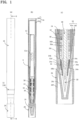
- FIG. 1 is an overall explanatory diagram showing an applicator according to a first embodiment.
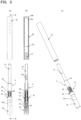
- FIG. 2 is an explanatory diagram showing a state where a rear barrel is detached from a front barrel while it is refilled.
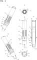
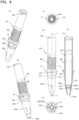
- FIGS. 3 , 4 , 5 and 6 are part diagrams showing the front barrel, a cap, the rear barrel, and an inner front barrel, respectively.
- the applicator includes a front barrel 14 to which an application liquid tank 12 for storing a liquid cosmetic to be fed to an applying part 10 is attached, and a rear barrel 16 that is attached to the front barrel 14 from the rear to cover the application liquid tank 12.
- the front barrel 14 has on its peripheral surface a male threaded portion 18 and a first engagement portion 20 formed in the circumferential direction and in the rear of the male threaded portion 18 (see FIG. 3 ).
- the rear barrel 16 (main body 16a) has on its inner circumferential surface a female threaded portion 22 to mate with the male threaded portion 18 and a second engagement portion 24 to be engaged with the first engagement portion 20 (see FIG. 5 ).
- the applicator is formed with a refill A in which a cap 26, the applying part 10, the front barrel 14, the inner front barrel 34, a collector 36, and the application liquid tank 12 are assembled.
- the cap 26 that can be attached to the front barrel is provided to cover the applying part 10.
- First protrusions 28 are formed on the inner surface of the cap 26 while second protrusions 30 are formed on the peripheral surface of the front barrel 14 so that when the cap 26 is fitted to the front barrel 14 the first protrusion 28 and the second protrusion 30 can mesh with each other.
- the second protrusions 30 are formed on the endface of a flange 32 on the peripheral side of the front barrel 14.
- the applying part 10 is mounted inside the front barrel 14 on the front-end side via the inner front barrel 34 while a liquid cosmetic is stored in the application liquid tank 12 attached to the rear end side of the front barrel 14.
- the collector 36 is accommodated in the front barrel 14, and the application liquid tank 12 for storing a liquid cosmetic is mounted behind the collector 36.
- the flange 32 expands in diameter around the periphery of the front barrel 14, and shown in FIG. 1 , the cap 26 abuts the front side of the flange 32 while the front end of the rear barrel 16 is placed against the rear side of the flange 32.
- a relay core 38 is arranged through the axial center of the collector 36.
- the relay core 38 guides the liquid cosmetic material to the applying part 10.
- the front end of the applying part 10 inside the front barrel 14 is projected and exposed from an opening 34b (see FIG. 6 ) of the inner front barrel 34 at the distal end of the front barrel 14.
- the inner circumferential surface of the opening 34b of the inner front barrel 34 is in contact with the periphery of the applying part 10.
- the applicator is configured so that inside the front barrel 14 the tip of the relay core 38 in the collector 36 is inserted into the rear end of the applying part 10 to guide the cosmetic material, and the collector 36 leads the liquid cosmetic material to the applying part 10 through a liquid cosmetic feed groove (slit).
- the relay core 38 may be configured as a feeder formed with a liquid cosmetic feed groove made of fiber bundles or resin.
- the rear end portion of the applying part 10 is hollow inside and formed with a flange having an enlarged diameter to the outside.
- the front end of the relay core 38 is inserted in the hollow interior.
- the collector 36 Arranged inside the front barrel 14 is the collector 36, which has a function of temporarily retaining the liquid between multiple fins.
- the flange 32 is fixed in front barrel 14 by being pushed by the front end of collector 36.
- the relay core 38 in a hollow hole 36a of the collector 36 is configured to guide the liquid cosmetic from the application liquid tank 12 to the applying part 10.
- the application liquid tank 12 is fixed with its front end fitted in the rear portion of the front barrel 14.
- the hollow hole 36a is formed extending axially from the front end to the rear end inside the collector 36, and the relay core 38 is placed in the hollow hole 36a.
- a plurality of fins 36b are arranged at intervals on the periphery of the collector 36. They exert the function of the collector 36 so as to temporarily store the liquid therebetween by the capillary force.
- a slit (not shown) is formed in the longitudinal direction (axial direction) so as to cut through the fins 36b.
- the collector 36 allows the liquid cosmetic to flow in and out between the fins 36b through the slit.
- the hollow hole 36a may be formed with ribs so as to support the relay core 38 with the ribs.
- the collector 36 is mounted inside the front barrel 14. At the rear end of the collector 36, the hollow hole 36a and the slit face the front opening of the application liquid tank 12.
- the rear endface (rear end) of the relay core 38 mounted in the hollow hole 36a of the collector 36 is exposed to the application liquid tank 12, and the relay core 38 feeds the liquid (liquid cosmetic) forward from the application liquid tank 12 (toward the applying part 10) .
- the front part of the collector 36 is formed like a cup, and the brim of the cup fits into the inner circumferential surface 34c inside the inner front barrel 34 and is positioned in contact with apexes 34a1 (see FIG. 6 ).
- the brim of the cup of the collector 36 presses the rear end of the applying part 10 (the rear endface of the flange).
- the front end of the relay core 38 in the collector 36 is inserted into the rear end space of the applying part 10.
- the rear end of the collector 36 is exposed to the application liquid tank 12 so that the liquid cosmetic in the application liquid tank 12 flows through the slit and is stored between the fins 36b of the collector 36 when the internal pressure of the application liquid tank 12 rises for some reason such as a change in atmospheric pressure or temperature.
- the front barrel 14 is formed with a vent hole 14b for ventilating the inside and outside of the collector 36 for air-liquid replacement.
- the front portion of the application liquid tank 12 is fitted into the rear portion of the front barrel 14 (in the rear of the flange 32), and the rear part of the collector 36 mounted inside the front barrel 14 is placed adjacent to the inside of the front portion of the application liquid tank 12.
- the application liquid tank 12 accommodates together with the liquid (coating liquid a metallic or resinous stirring piece 12a having a rod shape (or having an appropriate shape such as a sphere) for stirring the liquid.
- the front barrel 14 has a roughly hollow cylindrical shape as a whole, with an opening 14a in the front-end part, behind which vent holes 14b for air ventilation penetrating through between the inner and outer circumferences are formed adjacently.
- vent holes 14b for air ventilation penetrating through between the inner and outer circumferences are formed adjacently.
- Formed on the peripheral side of the rear portion of the front barrel 14 are the male threaded portion 18 and the first engagement portion 20 formed circumferentially behind the male threaded portion 18.
- the flange 32 is expanded in diameter around the middle part behind the vent holes 14b in the front-end part of the front barrel 14.
- the rear portion is extended cylindrically from the flange 32, and the male threaded portion 18 is formed on the peripheral side of the rear part from a point adjacent to the rear end surface of the flange 32 up to a point leaving about a half of the rear part.
- the male threaded portion 18 has a projected male thread with a break in the middle of the thread.
- the first engagement portion 20 is formed such that bumps are arrayed in the circumferential direction. Also arrayed circumferentially on the inner circumferential surface of the rear end of the front barrel 14 are internal bumps 14c, which are formed to hold the application liquid tank 12.
- the second protrusions 30 On the peripheral side of the front barrel 14 behind a circumferential projection 14d, and next and forward to the flange 32, the second protrusions 30, which are plate-like ribs tapered radially outwards and extended in the front-to-rear direction, are arrayed circumferentially. As shown in FIG. 4 , the second protrusions 30 are configured to be engaged and mesh with the first protrusions 28 that are formed on the inner circumferential surface in the rear end of the cap 26, so that when the cap 26 is fitted to the front barrel 14, the relative rotation is restricted.
- a step 14e for engagement with the inner front barrel 34 is formed from the opening 14a to backward inside the front barrel 14.
- Formed between the vent holes 14b and the flange 32 of the front barrel 14 is the concave-convex circumferential projection 14d.
- the first circumferential projection 14d is engaged with a locking projection 26b of the cap 26 so as to prevent the cap from coming off in the front-rear direction.
- the rear barrel 16 is constructed such that an outer cylinder 16b with a closed rear end having a design on the outer surface is fixed by fitting or bonding to the peripheral side of the cylindrical main body 16a with a closed end.
- the rear barrel 16 has the female threaded portion 22 formed on the inner circumference of the main body 16a of the rear barrel 16 in a form of an inward thread mating with the male threaded portion 18.
- the second engagement portion 24 is formed in an annular projection (annular rib) projected inward in a semicylindrical shape over the entire circumference of the inner circumferential surface of the main body 16a of the rear barrel 16.
- the second engagement portion 24 may have another form such as a concave-convex structure as long as it can be engaged with and fixed to the first engagement portion 20.
- the rear barrel 16 has a substantially cylindrical shape with its rear end closed.
- the cosmetic liquid applicator has the cap 26 that can be attached to the front barrel 14 to cover the applying part 10.
- First projections 28 are formed on the inner surface of the cap 26.
- the second protrusions 30 are formed on the peripheral surface of the front barrel 14.
- the cap 26 has first protrusions 28, made of multiple ribs each extended in the front-to-rear direction and arranged in the circumferential direction on the inner surface of the rear end part.
- the second protrusions 30 are formed on the front endface of the flange 32 projected radially outwards over the entire circumference of the front barrel 14.
- the second protrusion 30 is formed in the shape of a wall or a rib that is narrow and elongated in the axial direction.
- the first protrusions 28 and the second protrusions 30 are configured to be able to mesh with each other when the cap 26 is mounted to the front barrel 14.
- the front barrel 14 rotates together with the cap 26 without being slid, so that the attachment and detachment of the rear barrel 16 with respect to the front barrel 14 can be reliably performed.
- the cap 26 has a constriction 26a formed on the peripheral surface thereof. That is, as shown in FIGS. 1 and 4 , the constriction 26a is formed such that the middle part of the peripheral side with respect to the front-rear direction is constricted to be smaller in diameter than the front and rear portions 26f and 26r. The whole of the cap 26 roughly assumes a hourglass-like shape. Since the cap 26 is formed with the constriction 26a, the effect is provided that the user can easily hold the constriction 26a of the cap 26 with fingers and easily attach and detach the cap 26.
- a conical inner sleeve 26c which is tapered and closed at distal end, is extended continuously from the rear portion 26r while the front portion 26f having a cylindrical shape is integrally formed outside the inner sleeve 26c.
- the cap 26 has a plurality of locking projections 26b for fixing that are arranged on its inner circumference adjacent to and in front of the first protrusions 28 so as to be engaged with the circumferential projection 14d of the front barrel 14. Therefore, when the locking projections 26b lock the circumferential projection 14d, the cap 26 becomes unlikely to come off from the front barrel 14, and the first protrusions 28 and the second protrusions 30 can be kept in mesh with each other, so that the rear barrel 16 can be reliably attached to and detached from the refill A.
- the cap 26 may be used as a temporary cap when the product is traded as a refill A, and after replacement of the refill A being attached to the rear barrel 16, the cap 26 may be replaced with the original decorative cap with a design provided on the peripheral side.
- the inner front barrel 34 is arranged on the interior circumference of the front barrel 14 with its tip projected from the opening 14a of the front barrel 14.
- the inner front barrel 34 has a tubular, roughly conical shape having an opening 34b at the tip and has ribs 34a of a triangular shape oriented rearwards and having a projected apex 34a1, formed on the inner circumferential surface in the rear part thereof.
- a flat inner circumferential surface 34c Formed from the rear end to the interior of the inner front barrel 34 is a flat inner circumferential surface 34c having a slightly tapered shape.
- the apexes 34a1 are projected radially inward in a stepped manner, from the inner circumferential surface 34c.
- an engaging step 34d for mating with the step (step 14e adjacent to the opening 14a (see FIG. 3 )) inside the front barrel 14 is formed on the peripheral side of the inner front barrel 34 near the middle part with respect to the axial direction.
- the applying part 10 can be combed or guided by the apexes 34a1 of the ribs 34a when the applying part 10 is assembled, thus the fiber of the applying part 10 can be guided into the inner front barrel 34 without being disordered so that the applying part10 can be attached neatly without re-assembling.
- the inner front barrel 34 may be formed integrally with the front barrel 14 by two-color molding or the like. It is preferable to use different colors to distinguish the inner front barrel 34 from the front barrel 14.
- the liquid cosmetic stored in the application liquid tank 12 preferably contains water, a water-soluble organic solvent, a film-forming agent, a coloring material, and an antiseptic as essential components.
- the coloring material can use at least one of titanium oxide, iron oxide, Prussian blue, and ultramarine.
- Titanium oxide preferably has a specific weight of 3.8 to 4.2 with a particle size of 200 to 500 nm in the cosmetic.
- Iron oxide preferably has a specific weight of 3.8 to 5.5 with a particle size of 90 to 600 nm in the cosmetic.
- Prussian blue preferably has a specific weight of 1.8 to 1.9 with a particle size of 80 to 300 nm in the cosmetic.
- Ultramarine preferably has a specific weight of 1.8 to 1.9 with a particle size of 300 to 600 nm in the cosmetic.
- particle size is a value obtained by measuring the liquid cosmetic (25°C) with a particle size analyzer F PAR-1000 (manufactured by Otsuka Electronics Co., Ltd.) using a dynamic light scattering method.
- coloring materials include: for example, organic pigments such as Blue No. 1 Al lake, Red No. 202, Red No. 220, Red No. 226, Red No. 228, Blue No. 201, Blue No. 204, Blue No. 404, Yellow No. 401, Yellow No. 205, Yellow No. 4 Al lake, Yellow No. 203 Al lake, Red No. 104 Al lake, carbon black, carmine; acid dyes such as Red No. 2, Red No. 3 (FD&C Red No. 3), Red No. 40 (FD&C Red No. 40), Red No. 102, Red No. 104 (D&C Red No. 28), Red No. 105, Red No. 106, Red No. 201 (D&C Red No. 6), Red No.
- organic pigments such as Blue No. 1 Al lake, Red No. 202, Red No. 220, Red No. 226, Red No. 228, Blue No. 201, Blue No. 204, Blue No. 404, Yellow No. 401, Yellow No. 205, Yellow No. 4
- Blue No. 1 (FD&C Blue No. 1), Blue No. 2 (FD&C Blue No. 2), Blue No. 203, Blue No. 205 (D&C Blue No. 4), Blue No. 403, Blue No. 404, Brown No. 201 (D&C Brown No. 1), Violet No. 401 (Ext. D&C Violet No. 2), Black No. 401; inorganic pigments already mentioned such as titanium oxide, iron oxide, Prussian blue, and ultramarine. At least one coloring material can be selected from the above and the coloring material is not particularly limited as long as it is used in aqueous cosmetics.
- the content of these coloring materials is preferably 0.05 to 30% of the total amount of the liquid cosmetic, more preferably 0.1 to 20% in terms of color development, suitable viscosity, and smooth discharge from a water-based cosmetic applicator equipped with an applicator.
- the water-soluble organic solvent that can be used is not particularly limited and any can be used as long as it is commonly used in cosmetics. Examples include ethanol, isopropanol, phenoxyethanol and the like.
- the content of the water-soluble organic solvent is preferably 0 to 20%, more preferably 8 to 15%, relative to the total amount of the liquid cosmetic.
- film-forming agent examples include emulsion resins of copolymers of one or more monomers selected from acrylic acid, methacrylic acid, their alkyl esters or derivatives, styrene, and vinyl acetate.
- the content of the film-forming agent is preferably 2 to 150, more preferably 2 to 10%, relative to the total amount of the liquid cosmetic in terms of solid content (resin content).
- the liquid cosmetic to be used contains water (inclusive of purified water, distilled water, ion-exchanged water, pure water, ultrapure water, etc.) as the solvent.
- the content of the water is the remainder of the above components and the aftermentioned optional components.
- liquid cosmetic to be used can contain, in addition to the above components, optional ingredients used in ordinary liquid cosmetics. Specifically, preservatives, antioxidants, neutralizers, ultraviolet absorbers, chelating agents, moisturizing agents, beauty ingredients, fragrances, viscosity modifiers, etc. can be contained in appropriate amounts within a range that does not impair the effects of the present invention.
- the liquid cosmetic to be used preferably has a viscosity of 2 to 9 mPa.s measured by an ELD type viscometer at a temperature of 25°C and a shear rate of 76.6S ⁇ and a surface tension of 34 mN/m or higher.
- the surface tension is the measurement obtained at a temperature of 25°C using a CBVP-Z type surface tensiometer (plate method) manufactured by Kyowa Interface Science Co., Ltd.
- the refill A is configured as an assembly of the cap 26, the applying part 10, the front barrel 14, the inner front barrel 34, the collector 36, the relay core 38 and the application liquid tank 12.
- the assembly can be put on the market as the refill A for replacement.
- the front barrel 14 has on its peripheral surface the male threaded portion 18 and the first engagement portion 20 formed in the circumferential direction in the rear of the male threaded portion 18, while the rear barrel 16 has on its inner circumferential surface the female threaded portion 22 to mate with the male threaded portion 18 and the second engagement portion 24 to be engaged with the first engagement portion 20. Accordingly, when the female threaded portion 22 of the rear barrel 16 is screwed onto the male threaded portion 18 of the front barrel 14, the engagement is established as the first engagement portion 20 rides over the second engagement portion 24, so that can be provided an excellent effect that the user can easily confirm the engagement between the rear barrel 16 the front barrel 14 from the touch of the engagement.
- the refill A is configured as an assembly of the applying part 10, the front barrel 14, the inner front barrel 34, the collector 36, the relay core 38 and the application liquid tank 12, so that the assembly can be put on the market as the refill A for replacement. Since the first protrusions 28 are engaged with the second protrusions 30 (see FIGS. 3 and 4 ), the relative rotation of the cap 26 to the front barrel 14 is restricted. When the rear barrel 16 is screwed in by holding the cap 26, the rear barrel 16 can be screwed completely into the front barrel 14 until the first engagement portion 20 becomes tightly engaged with the second engagement portion 24, thus making it possible to achieve correct attachment without fail.
- FIG. 7 is an overall explanatory diagram showing an applicator according to the second embodiment.
- FIG. 8 is a part drawing of a front barrel 14B.
- FIG. 9 is a part drawing of a cap 26B.
- the same reference numerals are allotted to the same parts as in the first embodiment.
- the applicator is formed with a refill B in which a cap 26B, an applying part 10, a front barrel 14B, a collector 36, and an application liquid tank 12 are assembled.
- This applicator is different from the first embodiment in the overall configuration of the cap 26B and the partial configuration of the front barrel 14B, while is otherwise the same.
- the cap 26B that can be mounted to the front barrel 14B is provided to cover the applying part 10.
- First protrusions 28B are formed on the inner surface in the rear end part of the cap 26B (on the side into which the front barrel 14B is fitted) while second protrusions 30B are formed on the peripheral surface of the front barrel 14B so that the first protrusion 28B and the second protrusion 30B can engage with each other for anti-falling when the cap 26B is fitted to the front barrel 14B.
- the second protrusions 30B are formed and extended from the front endface of a flange 32 on the peripheral side of the front barrel 14B.
- the front barrel 14B is integrally formed up to front-end part and has a structure similar to that of a separated inner front barrel 34 of the first embodiment at a front-end portion 14Bf of the front barrel 14B.
- the first engagement portion 20B is formed to be a rib elongated in the circumferential direction.
- the front barrel 14B has a generally hollow cylindrical shape as a whole, and the front-end portion 14Bf has a tapered peripheral surface extending rearwards from the opening 14Ba at the tip, having vent holes 14Bb for air ventilation that come through a gap between the inner and outer circumferences.
- the front-end portion 14Bf has a hollow tapered configuration in which the same structure as the inner front barrel 34 of the first embodiment is integrated with the front barrel 14B.
- a stepped portion 14Bc is formed inside the position where the vent holes 14Bb are, and the inner circumference of the stepped portion form a tapered bore that extends to the opening 14Ba.
- a rib 34Ba having triangular apexes 34Ba1 projected rearwards is formed on the inner circumferential surface in front of the positioning portion 14Bd.
- a male threaded portion 18B Formed on the peripheral side behind the flange 32 in the front barrel 14B is a male threaded portion 18B and a first engagement portion 20B that is located behind the male threaded portion 18B and elongated along the circumferential direction.
- the male threaded portion 18B is a convex male thread with no break in the middle of the thread.
- a plurality of second protrusions 30B which are formed to be plate-like ribs extended in the front-to-rear direction and have a flat radially outside face, are arrayed circumferentially.
- the applicator has the cap 26B that can be attached to the front barrel 14B to cover the applying part 10.
- First projections 28B are formed on the inner surface of the cap 26B.
- the second protrusions 30B are formed on the peripheral surface of the front barrel 14B.
- the cap 26B has first protrusions 28B of multiple ribs each extended in the front-to-rear direction and arranged in the circumferential direction on the inner surface of the rear end part.
- the first protrusion 28B has an inner circumferential end 28Ba formed in a flat hill shape.
- the first protrusion 28B and the second protrusion 30B are configured to mesh with each other.
- the second protrusion 30 of the front barrel 14B is engaged and meshes with the first protrusion 28B formed on the inner circumferential surface of the rear end of the cap 26B. In the state where the cap 26B is fitted to the front barrel 14B, relative rotation is restricted.
- the inner circumferential end 28Ba of the first protrusion 28B is flat, and the second protrusion 30B of the front barrel 14B has a flat radially outward end.
- the first protrusion 28B and the second protrusion 30B are flat, the first protrusion 28B and the second protrusions 30B can easily ride over each other when the cap 26B is attached to the front barrel 14B. After riding over one another, the second protrusion 30B and the first protrusions 28B are rotated, the relative rotation therebetween is restricted. In addition, because of the easiness to ride over, the applied force can be dispersed, so that it is possible to reliably prevent breakage of one or both of the first protrusion 28B and the second protrusion 30B due to abutment.
- the cap 26B has a constriction 26Ba formed on the peripheral surface thereof. That is, as shown in FIG. 9 , the constriction 26a is formed such that the middle part of the peripheral side with respect to the front-rear direction is constricted to be smaller in diameter than the front and portions 26Bf and 26Br. That is, the whole of the cap 26B roughly assumes a hourglass-like shape. Since, similar to the first embodiment, the cap 26B is formed with the constriction 26Ba, the user can easily hold the constriction 26a of the cap 26B with their fingers to easily attach and detach the cap 26B.
- the cap 26B since the front-end portion 26Bf is closed with a flat end, the cap 26B has an approximately hourglass shape as a whole, so that no inner sleeve 26c as in the first embodiment is provided, which simplifies the shape of the cap.
- a plurality of locking projections 26Bb for fixing that are arrayed circumferentially adjacent to the first protrusions 28B and engaged with the circumferential projection 14d of the front barrel 14B.
- axially elongated ribs 26Be are standing on the inner circumferential side in front of the locking projections 26Bb.
- the applicator of the present invention can be used as an applicator for a coating liquid.
Landscapes
- Coating Apparatus (AREA)
Abstract
Description
- This disclosure relates to an applicator for applying a coating liquid such as cosmetics.
- Conventionally, there have been applicators which include: a collector that is a comb-like feed member for temporarily storing a coating liquid to be supplied to the applying part, inside the front barrel from the front end of which the applying part is projected; and an application liquid tank that is installed from behind in the front barrel so that the coating liquid inside the application liquid tank can flow to the collector and the applying part.
- In the applicators of this kind, as the structure that lets the outer barrel covering the application liquid tank fit to the front barrel from the rear of the front barrel, there is a configuration in which a projection for fixing the outer barrel is formed radially outwards at the rear end on the peripheral surface of the front barrel (e.g., see Patent Document 1).
- Patent Document 1:
Japanese Patent Application Laid-open No.2018-192242 - In the applicator of Patent Document 1, upon replacement of the application liquid tank, the outer barrel is fitted to the peripheral surface of the front barrel and fixed in such a manner that the projection on the front barrel is engaged with the inner circumferential surface of the outer barrel, so there is a problem that it is difficult to know whether the replacement is completed.
- Under such circumstances, the present application is to provide a cosmetic liquid applicator which allows easy determination of the completion of replacement of the application liquid tank.
- The embodiment of the present disclosure is an applicator, comprising: a front barrel to which an application liquid tank for storing a liquid cosmetic to be fed to an applying part is attached; and a rear barrel attached to the front barrel to cover the application liquid tank, wherein: the front barrel has on the peripheral surface thereof a male threaded portion and a first engagement portion formed in the circumferential direction and located in the rear of the male threaded portion; and the rear barrel has on the inner circumferential surface thereof a female threaded portion to mate with the male threaded portion and a second engagement portion to be engaged with the first engagement portion.
- In the embodiment of the present disclosure, it is preferable that a cap that can be attached to the front barrel to cover the applying part is provided, in which first protrusions are formed on the inner surface of the cap while second protrusions are formed on the peripheral surface of the front barrel so that when the cap is fitted to the front barrel, the first protrusion and the second protrusion can mesh with each other, and the second protrusions are formed on the endface of a flange on the peripheral side of the front barrel.
- In the embodiment of the present disclosure, it is preferable that the cap has a concave formed on the peripheral surface thereof.
- In the embodiment of the present disclosure, it is preferable that an inner front barrel is provided on the inner circumference of the front barrel, and on the inner circumferential surface of the inner front barrel is formed triangular apices.
- According to the applicator of the embodiment of the present disclosure, the front barrel has on the peripheral surface thereof a male threaded portion and a first engagement portion formed in the circumferential direction and located in the rear of the male threaded portion; and the rear barrel has on the inner circumferential surface thereof a female threaded portion to mate with the male threaded portion and a second engagement portion to be engaged with the first engagement portion. Therefore, when the female threaded portion of the rear barrel is screwed onto the male threaded portion of the front barrel, the first engagement portion and the second engagement portion are engaged with each other. As a result, the excellent effect is obtained that it is possible for a user to easily confirm that the rear barrel has been engaged with the front barrel from the feeling of the engagement.
-
- [
FIG. 1 ] An explanatory diagram of an applicator according to a first embodiment of the present disclosure, where (a) is an overall front view, (b) is a longitudinal sectional view taken along line B-B of (a), and (c) is an enlarged longitudinal sectional view of the front part. - [
FIG. 2 ] An explanatory diagram of the applicator inFIG. 1 with the rear barrel detached from the front barrel, where (a) is an overall front view, (b) is a longitudinal sectional view along line B-B of (a), and (c) is a perspective view from the front. - [
FIG. 3 ] A part diagram of the front barrel of the applicator ofFIG. 1 , where (a) is a perspective view from the rear, (b) is a perspective view from the front, and (c) is a view from the rear, (d) is a front view, (e) is a view from the front, and (f) is a vertical sectional view taken along line F-F of (d). - [
FIG. 4 ] A part diagram of a cap in the applicator ofFIG. 1 , where (a) is a perspective view from the rear, (b) is a perspective view from the front, (c) is a view from the rear, (d) is a front view, (e) is a view from the front, and (f) is a longitudinal sectional view taken along line F-F of (d). - [
FIG. 5 ] A vertically sectioned part diagram of a rear barrel of the applicator ofFIG. 1 . - [
FIG. 6 ] A part diagram of an inner front barrel of the applicator ofFIG. 1 , where (a) is a perspective view from the rear, (b) is a perspective view from the front, (c) is a view from the rear, and (d) is a front view. - [
FIG. 7 ] An explanatory diagram of an applicator according to the second embodiment of the present disclosure, where (a) is an overall front view, (b) is a vertical sectional view along line B-B of (a), and (c) is an enlarged longitudinal sectional view of the front part. - [
FIG. 8 ] A part diagram of a front barrel in the applicator ofFIG. 7 , where (a) is a perspective view from the rear, (b) is a perspective view from the front, (c) is a view from the rear, (d) is a front view, (e) is a view from the front, and (f) is a longitudinal sectional view taken along line F-F of (d). - [
FIG. 9 ] A part diagram of a cap in the applicator ofFIG. 7 , where (a) is a perspective view from the rear, (b) is a perspective view from the front, (c) is a view from the rear, (d) is a front view, (e) is a view from the front, (f) is a detailed view of part F of (a), and (g) is a longitudinal sectional view taken along line G-G of (d). - Hereinafter, embodiments of the present disclosure will be described with reference to the accompanying drawings.
-
FIG. 1 is an overall explanatory diagram showing an applicator according to a first embodiment.FIG. 2 is an explanatory diagram showing a state where a rear barrel is detached from a front barrel while it is refilled.FIGS. 3 ,4 ,5 and6 are part diagrams showing the front barrel, a cap, the rear barrel, and an inner front barrel, respectively. - As shown in
FIGs. 1 and2 , the applicator according to the first embodiment includes afront barrel 14 to which anapplication liquid tank 12 for storing a liquid cosmetic to be fed to an applyingpart 10 is attached, and arear barrel 16 that is attached to thefront barrel 14 from the rear to cover theapplication liquid tank 12. Thefront barrel 14 has on its peripheral surface a male threadedportion 18 and afirst engagement portion 20 formed in the circumferential direction and in the rear of the male threaded portion 18 (seeFIG. 3 ). The rear barrel 16 (main body 16a) has on its inner circumferential surface a female threadedportion 22 to mate with the male threadedportion 18 and asecond engagement portion 24 to be engaged with the first engagement portion 20 (seeFIG. 5 ). - As shown in
FIGs. 1 and2 , the applicator is formed with a refill A in which acap 26, the applyingpart 10, thefront barrel 14, theinner front barrel 34, acollector 36, and theapplication liquid tank 12 are assembled. - As shown in
FIGs. 3 and4 , thecap 26 that can be attached to the front barrel is provided to cover the applyingpart 10.First protrusions 28 are formed on the inner surface of thecap 26 whilesecond protrusions 30 are formed on the peripheral surface of thefront barrel 14 so that when thecap 26 is fitted to thefront barrel 14 thefirst protrusion 28 and thesecond protrusion 30 can mesh with each other. Thesecond protrusions 30 are formed on the endface of aflange 32 on the peripheral side of thefront barrel 14. - In this applicator, the applying
part 10 is mounted inside thefront barrel 14 on the front-end side via theinner front barrel 34 while a liquid cosmetic is stored in theapplication liquid tank 12 attached to the rear end side of thefront barrel 14. - The
collector 36 is accommodated in thefront barrel 14, and the applicationliquid tank 12 for storing a liquid cosmetic is mounted behind thecollector 36. Theflange 32 expands in diameter around the periphery of thefront barrel 14, and shown inFIG. 1 , thecap 26 abuts the front side of theflange 32 while the front end of therear barrel 16 is placed against the rear side of theflange 32. - A
relay core 38 is arranged through the axial center of thecollector 36. Therelay core 38 guides the liquid cosmetic material to the applyingpart 10. - In the applicator, the front end of the applying
part 10 inside thefront barrel 14 is projected and exposed from an opening 34b (seeFIG. 6 ) of theinner front barrel 34 at the distal end of thefront barrel 14. The inner circumferential surface of the opening 34b of the innerfront barrel 34 is in contact with the periphery of the applyingpart 10. - The applicator is configured so that inside the
front barrel 14 the tip of therelay core 38 in thecollector 36 is inserted into the rear end of the applyingpart 10 to guide the cosmetic material, and thecollector 36 leads the liquid cosmetic material to the applyingpart 10 through a liquid cosmetic feed groove (slit). In thecollector 36, therelay core 38 may be configured as a feeder formed with a liquid cosmetic feed groove made of fiber bundles or resin. - In the cosmetic applicator, as shown in
FIG. 1 , the rear end portion of the applyingpart 10 is hollow inside and formed with a flange having an enlarged diameter to the outside. The front end of therelay core 38 is inserted in the hollow interior. - Arranged inside the
front barrel 14 is thecollector 36, which has a function of temporarily retaining the liquid between multiple fins. Theflange 32 is fixed infront barrel 14 by being pushed by the front end ofcollector 36. Therelay core 38 in ahollow hole 36a of thecollector 36 is configured to guide the liquid cosmetic from theapplication liquid tank 12 to the applyingpart 10. - The application
liquid tank 12 is fixed with its front end fitted in the rear portion of thefront barrel 14. - As shown in
FIG. 1 , thehollow hole 36a is formed extending axially from the front end to the rear end inside thecollector 36, and therelay core 38 is placed in thehollow hole 36a. A plurality offins 36b are arranged at intervals on the periphery of thecollector 36. They exert the function of thecollector 36 so as to temporarily store the liquid therebetween by the capillary force. A slit (not shown) is formed in the longitudinal direction (axial direction) so as to cut through thefins 36b. Thecollector 36 allows the liquid cosmetic to flow in and out between thefins 36b through the slit. Thehollow hole 36a may be formed with ribs so as to support therelay core 38 with the ribs. - The
collector 36 is mounted inside thefront barrel 14. At the rear end of thecollector 36, thehollow hole 36a and the slit face the front opening of theapplication liquid tank 12. - The rear endface (rear end) of the
relay core 38 mounted in thehollow hole 36a of thecollector 36 is exposed to theapplication liquid tank 12, and therelay core 38 feeds the liquid (liquid cosmetic) forward from the application liquid tank 12 (toward the applying part 10) . - The front part of the
collector 36 is formed like a cup, and the brim of the cup fits into the innercircumferential surface 34c inside the innerfront barrel 34 and is positioned in contact with apexes 34a1 (seeFIG. 6 ). The brim of the cup of thecollector 36 presses the rear end of the applying part 10 (the rear endface of the flange). Also, the front end of therelay core 38 in thecollector 36 is inserted into the rear end space of the applyingpart 10. The rear end of thecollector 36 is exposed to theapplication liquid tank 12 so that the liquid cosmetic in theapplication liquid tank 12 flows through the slit and is stored between thefins 36b of thecollector 36 when the internal pressure of theapplication liquid tank 12 rises for some reason such as a change in atmospheric pressure or temperature. Thefront barrel 14 is formed with avent hole 14b for ventilating the inside and outside of thecollector 36 for air-liquid replacement. - Outside air flows into the
front barrel 14 through thevent hole 14b, so that the outside air circulates through thefins 36b and the slit around thecollector 36 held in thefront barrel 14. This ventilation inside thefront barrel 14 alleviates the fluctuation of the internal pressure of theapplication liquid tank 12 if it occurs, to thereby prevent the liquid cosmetic from blowing out from the applyingpart 10 and the like and prevent the liquid cosmetic from being chocked to flow. - As shown in
FIGS. 1 and2 , the front portion of theapplication liquid tank 12 is fitted into the rear portion of the front barrel 14 (in the rear of the flange 32), and the rear part of thecollector 36 mounted inside thefront barrel 14 is placed adjacent to the inside of the front portion of theapplication liquid tank 12. Theapplication liquid tank 12 accommodates together with the liquid (coating liquid a metallic orresinous stirring piece 12a having a rod shape (or having an appropriate shape such as a sphere) for stirring the liquid. - As shown in
FIG. 3 , thefront barrel 14 has a roughly hollow cylindrical shape as a whole, with anopening 14a in the front-end part, behind which ventholes 14b for air ventilation penetrating through between the inner and outer circumferences are formed adjacently. Formed on the peripheral side of the rear portion of thefront barrel 14 are the male threadedportion 18 and thefirst engagement portion 20 formed circumferentially behind the male threadedportion 18. - Specifically, the
flange 32 is expanded in diameter around the middle part behind the vent holes 14b in the front-end part of thefront barrel 14. The rear portion is extended cylindrically from theflange 32, and the male threadedportion 18 is formed on the peripheral side of the rear part from a point adjacent to the rear end surface of theflange 32 up to a point leaving about a half of the rear part. The male threadedportion 18 has a projected male thread with a break in the middle of the thread. - As shown in
FIG. 3 , near the rear end of the cylindrical rear part of thefront barrel 14, thefirst engagement portion 20 is formed such that bumps are arrayed in the circumferential direction. Also arrayed circumferentially on the inner circumferential surface of the rear end of thefront barrel 14 areinternal bumps 14c, which are formed to hold theapplication liquid tank 12. - On the peripheral side of the
front barrel 14 behind acircumferential projection 14d, and next and forward to theflange 32, thesecond protrusions 30, which are plate-like ribs tapered radially outwards and extended in the front-to-rear direction, are arrayed circumferentially. As shown inFIG. 4 , thesecond protrusions 30 are configured to be engaged and mesh with thefirst protrusions 28 that are formed on the inner circumferential surface in the rear end of thecap 26, so that when thecap 26 is fitted to thefront barrel 14, the relative rotation is restricted. - Additionally, a
step 14e for engagement with the innerfront barrel 34 is formed from theopening 14a to backward inside thefront barrel 14. Formed between the vent holes 14b and theflange 32 of thefront barrel 14 is the concave-convexcircumferential projection 14d. As shown inFIG. 4 , the firstcircumferential projection 14d is engaged with a lockingprojection 26b of thecap 26 so as to prevent the cap from coming off in the front-rear direction. - As shown in
FIG. 2 , therear barrel 16 is constructed such that anouter cylinder 16b with a closed rear end having a design on the outer surface is fixed by fitting or bonding to the peripheral side of the cylindricalmain body 16a with a closed end. - Detailedly, as shown in
FIG. 5 , therear barrel 16 has the female threadedportion 22 formed on the inner circumference of themain body 16a of therear barrel 16 in a form of an inward thread mating with the male threadedportion 18. Formed behind the female threadedportion 22 is thesecond engagement portion 24 for engaging with thefirst engagement portion 20 of thefront barrel 14. Thesecond engagement portion 24 is formed in an annular projection (annular rib) projected inward in a semicylindrical shape over the entire circumference of the inner circumferential surface of themain body 16a of therear barrel 16. Thesecond engagement portion 24 may have another form such as a concave-convex structure as long as it can be engaged with and fixed to thefirst engagement portion 20. Further, therear barrel 16 has a substantially cylindrical shape with its rear end closed. - When the
rear barrel 16 is mounted to thefront barrel 14, as shown inFIG. 2 , the front end of therear barrel 16 is fitted on the peripheral side of the rear part of thefront barrel 14 so as to cover theapplication liquid tank 12. Then, the rear barrel is turned clockwise so as to screw the female threadedportion 22 of therear barrel 16 onto the male threadedportion 18 of thefront barrel 14, whereby thefirst engagement portion 20 is made ride over thesecond engagement portion 24, establishing tight engagement and fixation as shown inFIG. 1 . When the female threadedportion 22 of therear barrel 16 is screwed onto the male threadedportion 18 of thefront barrel 14, the engagement is established as thefirst engagement portion 20 rides over thesecond engagement portion 24. As a result, the user can easily confirm that therear barrel 16 has been engaged with thefront barrel 14 from the impact of the engagement. - As shown in
FIG. 1 , the cosmetic liquid applicator has thecap 26 that can be attached to thefront barrel 14 to cover the applyingpart 10.First projections 28 are formed on the inner surface of thecap 26. As shown inFIG. 3 , thesecond protrusions 30 are formed on the peripheral surface of thefront barrel 14. When thecap 26 is mounted to thefront barrel 14, thefirst protrusion 28 and thesecond protrusion 30 mesh with each other, and thesecond protrusions 30 are formed on the endface of theflange 32 on the periphery of thefront barrel 14. - Specifically, as shown in
FIG. 4 , thecap 26 hasfirst protrusions 28, made of multiple ribs each extended in the front-to-rear direction and arranged in the circumferential direction on the inner surface of the rear end part. - As shown in
FIG. 3 , thesecond protrusions 30 are formed on the front endface of theflange 32 projected radially outwards over the entire circumference of thefront barrel 14. Thesecond protrusion 30 is formed in the shape of a wall or a rib that is narrow and elongated in the axial direction. - Accordingly, the
first protrusions 28 and thesecond protrusions 30 are configured to be able to mesh with each other when thecap 26 is mounted to thefront barrel 14. As will be described later, when a refill A is replaced, by turning therear barrel 16 while holding thecap 26, thefront barrel 14 rotates together with thecap 26 without being slid, so that the attachment and detachment of therear barrel 16 with respect to thefront barrel 14 can be reliably performed. - Also, the
cap 26 has aconstriction 26a formed on the peripheral surface thereof. That is, as shown inFIGS. 1 and4 , theconstriction 26a is formed such that the middle part of the peripheral side with respect to the front-rear direction is constricted to be smaller in diameter than the front andrear portions cap 26 roughly assumes a hourglass-like shape. Since thecap 26 is formed with theconstriction 26a, the effect is provided that the user can easily hold theconstriction 26a of thecap 26 with fingers and easily attach and detach thecap 26. - A conical
inner sleeve 26c which is tapered and closed at distal end, is extended continuously from therear portion 26r while thefront portion 26f having a cylindrical shape is integrally formed outside theinner sleeve 26c. - The
cap 26 has a plurality of lockingprojections 26b for fixing that are arranged on its inner circumference adjacent to and in front of thefirst protrusions 28 so as to be engaged with thecircumferential projection 14d of thefront barrel 14. Therefore, when the lockingprojections 26b lock thecircumferential projection 14d, thecap 26 becomes unlikely to come off from thefront barrel 14, and thefirst protrusions 28 and thesecond protrusions 30 can be kept in mesh with each other, so that therear barrel 16 can be reliably attached to and detached from the refill A. - In addition, the
cap 26 may be used as a temporary cap when the product is traded as a refill A, and after replacement of the refill A being attached to therear barrel 16, thecap 26 may be replaced with the original decorative cap with a design provided on the peripheral side. - As shown in
FIG. 1 , the innerfront barrel 34 is arranged on the interior circumference of thefront barrel 14 with its tip projected from theopening 14a of thefront barrel 14. - Detailedly, as shown in
FIG. 6 the innerfront barrel 34 has a tubular, roughly conical shape having anopening 34b at the tip and hasribs 34a of a triangular shape oriented rearwards and having a projected apex 34a1, formed on the inner circumferential surface in the rear part thereof. - Formed from the rear end to the interior of the inner
front barrel 34 is a flat innercircumferential surface 34c having a slightly tapered shape. The apexes 34a1 are projected radially inward in a stepped manner, from the innercircumferential surface 34c. - In addition, an engaging
step 34d for mating with the step (step 14e adjacent to theopening 14a (seeFIG. 3 )) inside thefront barrel 14 is formed on the peripheral side of the innerfront barrel 34 near the middle part with respect to the axial direction. - Since the inner
front barrel 34 hasribs 34a having apexes 34a1 therein, the applyingpart 10 can be combed or guided by the apexes 34a1 of theribs 34a when the applyingpart 10 is assembled, thus the fiber of the applyingpart 10 can be guided into the innerfront barrel 34 without being disordered so that the applying part10 can be attached neatly without re-assembling. - Alternatively, the inner
front barrel 34 may be formed integrally with thefront barrel 14 by two-color molding or the like. It is preferable to use different colors to distinguish the innerfront barrel 34 from thefront barrel 14. - The liquid cosmetic stored in the
application liquid tank 12 preferably contains water, a water-soluble organic solvent, a film-forming agent, a coloring material, and an antiseptic as essential components. - More specifically, the coloring material can use at least one of titanium oxide, iron oxide, Prussian blue, and ultramarine. Titanium oxide preferably has a specific weight of 3.8 to 4.2 with a particle size of 200 to 500 nm in the cosmetic. Iron oxide preferably has a specific weight of 3.8 to 5.5 with a particle size of 90 to 600 nm in the cosmetic. Prussian blue preferably has a specific weight of 1.8 to 1.9 with a particle size of 80 to 300 nm in the cosmetic. Ultramarine preferably has a specific weight of 1.8 to 1.9 with a particle size of 300 to 600 nm in the cosmetic. Here, in the present invention, "particle size" is a value obtained by measuring the liquid cosmetic (25°C) with a particle size analyzer F PAR-1000 (manufactured by Otsuka Electronics Co., Ltd.) using a dynamic light scattering method.
- Other coloring materials that can be used include: for example, organic pigments such as Blue No. 1 Al lake, Red No. 202, Red No. 220, Red No. 226, Red No. 228, Blue No. 201, Blue No. 204, Blue No. 404, Yellow No. 401, Yellow No. 205, Yellow No. 4 Al lake, Yellow No. 203 Al lake, Red No. 104 Al lake, carbon black, carmine; acid dyes such as Red No. 2, Red No. 3 (FD&C Red No. 3), Red No. 40 (FD&C Red No. 40), Red No. 102, Red No. 104 (D&C Red No. 28), Red No. 105, Red No. 106, Red No. 201 (D&C Red No. 6), Red No. 202 (D&C Red No. 7), Red No. 203, Red No. 205, Red No. 227 (D&C Red No. 33), Red No. 230-1 (D&C Red No. 22), Red No. 401 Red No. 402, Red No. 504 (FD&C Red No. 4), Orange No. 205 (D&C Orange No. 4), Orange No. 402, Yellow No. 4 (FD&C Yellow No. 5), Yellow No. 5 (FD&C Yellow No. 6), Yellow No. 203 (D&C Yellow No. 10), Yellow No. 402, Yellow No. 403-1 (Ext. D&CYellow No. 7), Yellow No. 406, Yellow No. 407, Green No. 3 (FD&C Green No. 3), Green No. 201, Green No. 402, Blue No. 1 (FD&C Blue No. 1), Blue No. 2 (FD&C Blue No. 2), Blue No. 203, Blue No. 205 (D&C Blue No. 4), Blue No. 403, Blue No. 404, Brown No. 201 (D&C Brown No. 1), Violet No. 401 (Ext. D&C Violet No. 2), Black No. 401; inorganic pigments already mentioned such as titanium oxide, iron oxide, Prussian blue, and ultramarine. At least one coloring material can be selected from the above and the coloring material is not particularly limited as long as it is used in aqueous cosmetics.
- The content of these coloring materials is preferably 0.05 to 30% of the total amount of the liquid cosmetic, more preferably 0.1 to 20% in terms of color development, suitable viscosity, and smooth discharge from a water-based cosmetic applicator equipped with an applicator.
- The water-soluble organic solvent that can be used is not particularly limited and any can be used as long as it is commonly used in cosmetics. Examples include ethanol, isopropanol, phenoxyethanol and the like.
- The content of the water-soluble organic solvent is preferably 0 to 20%, more preferably 8 to 15%, relative to the total amount of the liquid cosmetic.
- Examples of the film-forming agent that can be used include emulsion resins of copolymers of one or more monomers selected from acrylic acid, methacrylic acid, their alkyl esters or derivatives, styrene, and vinyl acetate.
- The content of the film-forming agent (emulsion resin) is preferably 2 to 150, more preferably 2 to 10%, relative to the total amount of the liquid cosmetic in terms of solid content (resin content).
- The liquid cosmetic to be used contains water (inclusive of purified water, distilled water, ion-exchanged water, pure water, ultrapure water, etc.) as the solvent. The content of the water is the remainder of the above components and the aftermentioned optional components.
- Furthermore, the liquid cosmetic to be used can contain, in addition to the above components, optional ingredients used in ordinary liquid cosmetics. Specifically, preservatives, antioxidants, neutralizers, ultraviolet absorbers, chelating agents, moisturizing agents, beauty ingredients, fragrances, viscosity modifiers, etc. can be contained in appropriate amounts within a range that does not impair the effects of the present invention.
- In order to smoothly discharge the coating liquid from the applicator and in order to exhibit good application performance, the liquid cosmetic to be used preferably has a viscosity of 2 to 9 mPa.s measured by an ELD type viscometer at a temperature of 25°C and a shear rate of 76.6S^ and a surface tension of 34 mN/m or higher. Here, the surface tension is the measurement obtained at a temperature of 25°C using a CBVP-Z type surface tensiometer (plate method) manufactured by Kyowa Interface Science Co., Ltd.
- Here, as shown in
FIG. 2 the refill A is configured as an assembly of thecap 26, the applyingpart 10, thefront barrel 14, the innerfront barrel 34, thecollector 36, therelay core 38 and theapplication liquid tank 12. The assembly can be put on the market as the refill A for replacement. - According to the cosmetic liquid applicator according to the first embodiment, as shown in
FIG. 2 , thefront barrel 14 has on its peripheral surface the male threadedportion 18 and thefirst engagement portion 20 formed in the circumferential direction in the rear of the male threadedportion 18, while therear barrel 16 has on its inner circumferential surface the female threadedportion 22 to mate with the male threadedportion 18 and thesecond engagement portion 24 to be engaged with thefirst engagement portion 20. Accordingly, when the female threadedportion 22 of therear barrel 16 is screwed onto the male threadedportion 18 of thefront barrel 14, the engagement is established as thefirst engagement portion 20 rides over thesecond engagement portion 24, so that can be provided an excellent effect that the user can easily confirm the engagement between therear barrel 16 thefront barrel 14 from the touch of the engagement. - Further, as shown in
FIG. 2 the refill A is configured as an assembly of the applyingpart 10, thefront barrel 14, the innerfront barrel 34, thecollector 36, therelay core 38 and theapplication liquid tank 12, so that the assembly can be put on the market as the refill A for replacement. Since thefirst protrusions 28 are engaged with the second protrusions 30 (seeFIGS. 3 and4 ), the relative rotation of thecap 26 to thefront barrel 14 is restricted. When therear barrel 16 is screwed in by holding thecap 26, therear barrel 16 can be screwed completely into thefront barrel 14 until thefirst engagement portion 20 becomes tightly engaged with thesecond engagement portion 24, thus making it possible to achieve correct attachment without fail. - Next, an applicator according to a second embodiment will be described.
-
FIG. 7 is an overall explanatory diagram showing an applicator according to the second embodiment.FIG. 8 is a part drawing of afront barrel 14B.FIG. 9 is a part drawing of acap 26B. In these figures of the applicator according to the second embodiment, the same reference numerals are allotted to the same parts as in the first embodiment. - As shown in
FIG. 7 , the applicator is formed with a refill B in which acap 26B, an applyingpart 10, afront barrel 14B, acollector 36, and anapplication liquid tank 12 are assembled. This applicator is different from the first embodiment in the overall configuration of thecap 26B and the partial configuration of thefront barrel 14B, while is otherwise the same. - As shown in
FIGS. 7 to 9 , thecap 26B that can be mounted to thefront barrel 14B is provided to cover the applyingpart 10.First protrusions 28B are formed on the inner surface in the rear end part of thecap 26B (on the side into which thefront barrel 14B is fitted) whilesecond protrusions 30B are formed on the peripheral surface of thefront barrel 14B so that thefirst protrusion 28B and thesecond protrusion 30B can engage with each other for anti-falling when thecap 26B is fitted to thefront barrel 14B. Thesecond protrusions 30B are formed and extended from the front endface of aflange 32 on the peripheral side of thefront barrel 14B. - As shown in
FIG. 8 , thefront barrel 14B is integrally formed up to front-end part and has a structure similar to that of a separated innerfront barrel 34 of the first embodiment at a front-end portion 14Bf of thefront barrel 14B. Further, thefirst engagement portion 20B is formed to be a rib elongated in the circumferential direction. - The
front barrel 14B has a generally hollow cylindrical shape as a whole, and the front-end portion 14Bf has a tapered peripheral surface extending rearwards from the opening 14Ba at the tip, having vent holes 14Bb for air ventilation that come through a gap between the inner and outer circumferences. - The front-end portion 14Bf has a hollow tapered configuration in which the same structure as the inner
front barrel 34 of the first embodiment is integrated with thefront barrel 14B. A stepped portion 14Bc is formed inside the position where the vent holes 14Bb are, and the inner circumference of the stepped portion form a tapered bore that extends to the opening 14Ba. Formed on the inner circumferential surface of the front-end portion 14Bf, located in front of the stepped portion 14Bc, is a tapered positioning portion 14Bd that receives and positions the cup-shaped distal end portion of thecollector 36 together with the applyingpart 10 therein. Further, a rib 34Ba having triangular apexes 34Ba1 projected rearwards is formed on the inner circumferential surface in front of the positioning portion 14Bd. - Formed on the peripheral side behind the
flange 32 in thefront barrel 14B is a male threadedportion 18B and afirst engagement portion 20B that is located behind the male threadedportion 18B and elongated along the circumferential direction. The male threadedportion 18B is a convex male thread with no break in the middle of the thread. - In addition, behind a
circumferential projection 14d of thefront barrel 14B and in front of the peripheral side adjacent to theflange 32, a plurality ofsecond protrusions 30B, which are formed to be plate-like ribs extended in the front-to-rear direction and have a flat radially outside face, are arrayed circumferentially. - As shown in
FIGS. 7 to 9 , the applicator has thecap 26B that can be attached to thefront barrel 14B to cover the applyingpart 10.First projections 28B are formed on the inner surface of thecap 26B. thesecond protrusions 30B are formed on the peripheral surface of thefront barrel 14B. When thecap 26B is attached to thefront barrel 14B, thefirst protrusion 28B and thesecond protrusion 30B mesh with each other, and thesecond protrusion 30B is formed on the endface of theflange 32 on the periphery of thefront barrel 14B. - Specifically, as shown in
FIG. 9 , thecap 26B hasfirst protrusions 28B of multiple ribs each extended in the front-to-rear direction and arranged in the circumferential direction on the inner surface of the rear end part. As shown inFIG. 9(f) , thefirst protrusion 28B has an inner circumferential end 28Ba formed in a flat hill shape. - Therefore, when the
cap 26B is attached to thefront barrel 14B, thefirst protrusion 28B and thesecond protrusion 30B are configured to mesh with each other. - The
second protrusion 30 of thefront barrel 14B is engaged and meshes with thefirst protrusion 28B formed on the inner circumferential surface of the rear end of thecap 26B. In the state where thecap 26B is fitted to thefront barrel 14B, relative rotation is restricted. - In addition, the inner circumferential end 28Ba of the
first protrusion 28B is flat, and thesecond protrusion 30B of thefront barrel 14B has a flat radially outward end. - Therefore, since the opposing distal ends of the
first protrusion 28B and thesecond protrusion 30B are flat, thefirst protrusion 28B and thesecond protrusions 30B can easily ride over each other when thecap 26B is attached to thefront barrel 14B. After riding over one another, thesecond protrusion 30B and thefirst protrusions 28B are rotated, the relative rotation therebetween is restricted. In addition, because of the easiness to ride over, the applied force can be dispersed, so that it is possible to reliably prevent breakage of one or both of thefirst protrusion 28B and thesecond protrusion 30B due to abutment. - Here, similarly to the refill A, in replacing refills B, when the
rear barrel 16 is turned by holding thecap 26B, thefront barrel 14 rotates together with thecap 26B without being slid, so that the attachment and detachment of therear barrel 16 with respect to thefront barrel 14B can be reliably performed. - Also, the
cap 26B has a constriction 26Ba formed on the peripheral surface thereof. That is, as shown inFIG. 9 , theconstriction 26a is formed such that the middle part of the peripheral side with respect to the front-rear direction is constricted to be smaller in diameter than the front and portions 26Bf and 26Br. That is, the whole of thecap 26B roughly assumes a hourglass-like shape. Since, similar to the first embodiment, thecap 26B is formed with the constriction 26Ba, the user can easily hold theconstriction 26a of thecap 26B with their fingers to easily attach and detach thecap 26B. - Further, since the front-end portion 26Bf is closed with a flat end, the
cap 26B has an approximately hourglass shape as a whole, so that noinner sleeve 26c as in the first embodiment is provided, which simplifies the shape of the cap. - In addition, on the inner circumferential side of the
cap 26B, a plurality of locking projections 26Bb for fixing that are arrayed circumferentially adjacent to thefirst protrusions 28B and engaged with thecircumferential projection 14d of thefront barrel 14B. As shown inFIG. 9 , axially elongated ribs 26Be are standing on the inner circumferential side in front of the locking projections 26Bb. Thus, as shown inFIG. 7 , thefront barrel 14B is supported from the periphery when thecap 26B is fitted to the front barrel, whereby thecap 26B can be prevented from rattling. - The above-described embodiment is an example of the present invention, and it goes without saying that modifications within the scope of the present invention should also be included within the technical scope.
- The applicator of the present invention can be used as an applicator for a coating liquid.
-
- 10
- applicator
- 12
- application liquid tank
- 14
- front barrel
- 14c
- internal bump
- 14d
- circumferential projection
- 14e
- step
- 14B
- front barrel
- 14Bf
- front-end portion
- 16
- rear barrel
- 16a
- main body
- 16b
- outer cylinder
- 18
- male threaded portion
- 18B
- male thread portion
- 20
- first engagement portion
- 20B
- first engagement portion
- 22
- female threaded portion
- 24
- second engagement portion
- 26
- cap
- 26a
- constriction
- 26b
- locking projection
- 26c
- inner sleeve
- 26f
- front portion
- 26r
- rear portion
- 26B
- cap
- 26Ba
- constriction
- 26Bb
- locking projection
- 26Be
- rib
- 26Bf
- front-end portion
- 28
- first protrusion
- 28B
- first protrusion
- 30
- second protrusion
- 30B
- second protrusion
- 32
- flange
- 34
- inner front barrel
- 34a
- rib
- 34a1
- apex
- 34b
- opening
- 34c
- inner circumferential surface
- 34d
- engaging step
- 34Ba
- rib
- 34Ba1
- apex
- 36
- collector
- 38
- relay core
- A
- refill
- B
- refill
Claims (4)
- An applicator, comprising:a front barrel to which an application liquid tank for storing a liquid cosmetic to be fed to an applying part is attached; anda rear barrel attached to the front barrel to cover the application liquid tank, wherein:the front barrel has on the peripheral surface thereof a male threaded portion and a first engagement portion formed in the circumferential direction and located in the rear of the male threaded portion; andthe rear barrel has on the inner circumferential surface thereof a female threaded portion to mate with the male threaded portion and a second engagement portion to be engaged with the first engagement portion.
- The applicator according to Claim 1, further comprising a cap that can be attached to the front barrel to cover the applying part,wherein first protrusions are formed on the inner surface of the cap and second protrusions are formed on the peripheral surface of the front barrel,so that when the cap is fitted to the front barrel, the first protrusion and the second protrusion mesh with each other,and the second protrusions are formed on the endface of a flange on the peripheral side of the front barrel.
- The applicator according to claim 2, wherein the cap has a constriction formed on the peripheral surface thereof.
- The applicator according to any one of claims 1 to 3, wherein an inner front barrel is provided on the inner circumference of the front barrel, and the inner circumferential surface of the inner front barrel is formed with triangular apexes.
Applications Claiming Priority (2)
| Application Number | Priority Date | Filing Date | Title |
|---|---|---|---|
| JP2020139994 | 2020-08-21 | ||
| PCT/JP2021/030471 WO2022039243A1 (en) | 2020-08-21 | 2021-08-19 | Applicator |
Publications (2)
| Publication Number | Publication Date |
|---|---|
| EP4201252A1 true EP4201252A1 (en) | 2023-06-28 |
| EP4201252A4 EP4201252A4 (en) | 2024-08-21 |
Family
ID=80323507
Family Applications (1)
| Application Number | Title | Priority Date | Filing Date |
|---|---|---|---|
| EP21858386.2A Pending EP4201252A4 (en) | 2020-08-21 | 2021-08-19 | APPLICATION DEVICE |
Country Status (6)
| Country | Link |
|---|---|
| US (1) | US12144412B2 (en) |
| EP (1) | EP4201252A4 (en) |
| JP (1) | JPWO2022039243A1 (en) |
| KR (1) | KR20230054392A (en) |
| CN (1) | CN116056802A (en) |
| WO (1) | WO2022039243A1 (en) |
Families Citing this family (1)
| Publication number | Priority date | Publication date | Assignee | Title |
|---|---|---|---|---|
| KR102899132B1 (en) * | 2023-05-11 | 2025-12-17 | 임프주식회사 | Portable beauty liquid filling tube cap combination jig |
Family Cites Families (16)
| Publication number | Priority date | Publication date | Assignee | Title |
|---|---|---|---|---|
| US4289248A (en) * | 1979-10-15 | 1981-09-15 | Becton, Dickinson And Company | Container closure assembly having intermediate positioning means |
| FR2520328A1 (en) * | 1982-01-22 | 1983-07-29 | Chanel | DEVICE FOR PREVENTING THE SELF-DISCARDING OF A PLUG ON A BOTTLE |
| FR2564070B2 (en) * | 1983-10-13 | 1987-04-30 | Oreal | BOTTLE COMPRISING AN ANGULARLY ORIENTED CAPPING DEVICE RELATIVE TO THE BOTTLE AUDIT |
| US6261019B1 (en) * | 1997-12-25 | 2001-07-17 | Mitsubishi Pencil Kabushiki Kaisha | Ball point pen |
| JP3420078B2 (en) * | 1998-09-02 | 2003-06-23 | タチカワ株式会社 | Writing implement |
| JP4748897B2 (en) * | 2001-08-15 | 2011-08-17 | 三菱鉛筆株式会社 | Writing instrument |
| CN100477939C (en) * | 2004-04-28 | 2009-04-15 | 株式会社吉野工业所 | Liquid applicator |
| JP3133495U (en) * | 2007-05-01 | 2007-07-12 | パイロットインキ株式会社 | Ink tank exchangeable writing instrument |
| JP5078505B2 (en) * | 2007-08-28 | 2012-11-21 | アサヌマ コーポレーション株式会社 | Liquid application member |
| JP5486296B2 (en) * | 2009-12-25 | 2014-05-07 | 花王株式会社 | Applicator |
| JP2015165866A (en) * | 2014-03-04 | 2015-09-24 | 鈴野化成株式会社 | cartridge type cosmetic container |
| JP7441598B2 (en) | 2017-05-16 | 2024-03-01 | 三菱鉛筆株式会社 | applicator |
| JP7401175B2 (en) * | 2017-05-16 | 2023-12-19 | 三菱鉛筆株式会社 | applicator |
| JP2020001193A (en) * | 2018-06-25 | 2020-01-09 | 株式会社パイロットコーポレーション | Thermochromic writing instrument |
| JP7158203B2 (en) * | 2018-08-07 | 2022-10-21 | 三菱鉛筆株式会社 | Applicator |
| JP7350487B2 (en) * | 2019-01-23 | 2023-09-26 | 三菱鉛筆株式会社 | cosmetic applicator |
-
2021
- 2021-08-19 EP EP21858386.2A patent/EP4201252A4/en active Pending
- 2021-08-19 CN CN202180055893.8A patent/CN116056802A/en active Pending
- 2021-08-19 JP JP2022544006A patent/JPWO2022039243A1/ja active Pending
- 2021-08-19 WO PCT/JP2021/030471 patent/WO2022039243A1/en not_active Ceased
- 2021-08-19 KR KR1020237008376A patent/KR20230054392A/en active Pending
- 2021-08-19 US US18/021,614 patent/US12144412B2/en active Active
Also Published As
| Publication number | Publication date |
|---|---|
| EP4201252A4 (en) | 2024-08-21 |
| US12144412B2 (en) | 2024-11-19 |
| CN116056802A (en) | 2023-05-02 |
| KR20230054392A (en) | 2023-04-24 |
| US20230292910A1 (en) | 2023-09-21 |
| WO2022039243A1 (en) | 2022-02-24 |
| JPWO2022039243A1 (en) | 2022-02-24 |
Similar Documents
| Publication | Publication Date | Title |
|---|---|---|
| US11084316B2 (en) | Applicator | |
| KR100897854B1 (en) | Liquid cosmetic applicator | |
| US9211756B2 (en) | Liquid applicator device | |
| EP4201252A1 (en) | Applicator | |
| JP2018192242A (en) | Applicator | |
| JP7394199B2 (en) | cosmetic applicator | |
| US20210093068A1 (en) | Hair dye container | |
| US20040005185A1 (en) | Cartridge type applicator | |
| CN115211654B (en) | Cosmetic container with application member | |
| JP6600515B2 (en) | Marking pen | |
| JP2602464Y2 (en) | Liquid applicator | |
| JP2017087531A (en) | Applicator | |
| JP3751378B2 (en) | Applicator brush mounting structure | |
| WO2025053263A1 (en) | Applicator | |
| JP2013237189A (en) | Writing implement refill and writing implement housing the same | |
| JPH0810405Y2 (en) | Ink tank type applicator | |
| WO2025258587A1 (en) | Applicator | |
| JPH077192Y2 (en) | Writing instrument | |
| BR112018010461B1 (en) | Ink cartridge and writing instrument | |
| JP2024165423A (en) | Application container |
Legal Events
| Date | Code | Title | Description |
|---|---|---|---|
| STAA | Information on the status of an ep patent application or granted ep patent |
Free format text: STATUS: THE INTERNATIONAL PUBLICATION HAS BEEN MADE |
|
| PUAI | Public reference made under article 153(3) epc to a published international application that has entered the european phase |
Free format text: ORIGINAL CODE: 0009012 |
|
| STAA | Information on the status of an ep patent application or granted ep patent |
Free format text: STATUS: REQUEST FOR EXAMINATION WAS MADE |
|
| 17P | Request for examination filed |
Effective date: 20230313 |
|
| AK | Designated contracting states |
Kind code of ref document: A1 Designated state(s): AL AT BE BG CH CY CZ DE DK EE ES FI FR GB GR HR HU IE IS IT LI LT LU LV MC MK MT NL NO PL PT RO RS SE SI SK SM TR |
|
| DAV | Request for validation of the european patent (deleted) | ||
| DAX | Request for extension of the european patent (deleted) | ||
| RAP3 | Party data changed (applicant data changed or rights of an application transferred) |
Owner name: MITSUBISHI PENCIL COMPANY, LIMITED |
|
| A4 | Supplementary search report drawn up and despatched |
Effective date: 20240723 |
|
| RIC1 | Information provided on ipc code assigned before grant |
Ipc: B43K 8/02 20060101ALI20240717BHEP Ipc: B05C 17/00 20060101ALI20240717BHEP Ipc: A45D 34/04 20060101AFI20240717BHEP |