EP4201243A1 - Shock absorber assembly, personal protective equipment therewith, deformable element for and method of retrofitting of such an assembly - Google Patents
Shock absorber assembly, personal protective equipment therewith, deformable element for and method of retrofitting of such an assembly Download PDFInfo
- Publication number
- EP4201243A1 EP4201243A1 EP21216403.2A EP21216403A EP4201243A1 EP 4201243 A1 EP4201243 A1 EP 4201243A1 EP 21216403 A EP21216403 A EP 21216403A EP 4201243 A1 EP4201243 A1 EP 4201243A1
- Authority
- EP
- European Patent Office
- Prior art keywords
- deformable element
- shock absorber
- absorber assembly
- strap
- protective equipment
- Prior art date
- Legal status (The legal status is an assumption and is not a legal conclusion. Google has not performed a legal analysis and makes no representation as to the accuracy of the status listed.)
- Withdrawn
Links
- 230000035939 shock Effects 0.000 title claims abstract description 164
- 239000006096 absorbing agent Substances 0.000 title claims abstract description 153
- 230000001681 protective effect Effects 0.000 title claims abstract description 121
- 238000000034 method Methods 0.000 title claims abstract description 16
- 238000009420 retrofitting Methods 0.000 title claims abstract description 9
- 230000000241 respiratory effect Effects 0.000 claims abstract description 21
- 238000003466 welding Methods 0.000 claims abstract description 19
- 230000001747 exhibiting effect Effects 0.000 claims abstract description 4
- 239000000463 material Substances 0.000 claims description 11
- 230000002427 irreversible effect Effects 0.000 claims description 6
- 239000012858 resilient material Substances 0.000 claims description 5
- 230000002441 reversible effect Effects 0.000 claims description 5
- 230000006378 damage Effects 0.000 abstract description 4
- 230000003116 impacting effect Effects 0.000 abstract description 3
- 230000008901 benefit Effects 0.000 description 18
- 238000010521 absorption reaction Methods 0.000 description 12
- 230000006870 function Effects 0.000 description 12
- 230000009286 beneficial effect Effects 0.000 description 11
- 230000008859 change Effects 0.000 description 7
- 230000007423 decrease Effects 0.000 description 7
- 239000004033 plastic Substances 0.000 description 6
- 229920003023 plastic Polymers 0.000 description 6
- 239000003973 paint Substances 0.000 description 4
- 230000008569 process Effects 0.000 description 4
- 239000000243 solution Substances 0.000 description 4
- 239000000725 suspension Substances 0.000 description 4
- 230000003247 decreasing effect Effects 0.000 description 3
- 230000005489 elastic deformation Effects 0.000 description 3
- 230000002829 reductive effect Effects 0.000 description 3
- 239000000853 adhesive Substances 0.000 description 2
- 230000001070 adhesive effect Effects 0.000 description 2
- 230000033228 biological regulation Effects 0.000 description 2
- 238000005520 cutting process Methods 0.000 description 2
- 238000001746 injection moulding Methods 0.000 description 2
- 238000004519 manufacturing process Methods 0.000 description 2
- 238000000465 moulding Methods 0.000 description 2
- 230000003287 optical effect Effects 0.000 description 2
- -1 polypropylene Polymers 0.000 description 2
- 230000009467 reduction Effects 0.000 description 2
- 238000004804 winding Methods 0.000 description 2
- 239000004952 Polyamide Substances 0.000 description 1
- 239000004698 Polyethylene Substances 0.000 description 1
- 239000004743 Polypropylene Substances 0.000 description 1
- 239000004793 Polystyrene Substances 0.000 description 1
- NIXOWILDQLNWCW-UHFFFAOYSA-N acrylic acid group Chemical group C(C=C)(=O)O NIXOWILDQLNWCW-UHFFFAOYSA-N 0.000 description 1
- XECAHXYUAAWDEL-UHFFFAOYSA-N acrylonitrile butadiene styrene Chemical compound C=CC=C.C=CC#N.C=CC1=CC=CC=C1 XECAHXYUAAWDEL-UHFFFAOYSA-N 0.000 description 1
- 239000004676 acrylonitrile butadiene styrene Substances 0.000 description 1
- 229920000122 acrylonitrile butadiene styrene Polymers 0.000 description 1
- 230000009471 action Effects 0.000 description 1
- 239000012790 adhesive layer Substances 0.000 description 1
- 230000004075 alteration Effects 0.000 description 1
- 230000002238 attenuated effect Effects 0.000 description 1
- 230000005540 biological transmission Effects 0.000 description 1
- 238000010276 construction Methods 0.000 description 1
- 230000007547 defect Effects 0.000 description 1
- 239000006260 foam Substances 0.000 description 1
- 230000036541 health Effects 0.000 description 1
- 229920001903 high density polyethylene Polymers 0.000 description 1
- 239000004700 high-density polyethylene Substances 0.000 description 1
- 239000010410 layer Substances 0.000 description 1
- 239000002184 metal Substances 0.000 description 1
- 230000036961 partial effect Effects 0.000 description 1
- 230000035515 penetration Effects 0.000 description 1
- 229920002647 polyamide Polymers 0.000 description 1
- 229920000515 polycarbonate Polymers 0.000 description 1
- 239000004417 polycarbonate Substances 0.000 description 1
- 229920006149 polyester-amide block copolymer Polymers 0.000 description 1
- 229920000573 polyethylene Polymers 0.000 description 1
- 229920001155 polypropylene Polymers 0.000 description 1
- 229920002223 polystyrene Polymers 0.000 description 1
- 239000004800 polyvinyl chloride Substances 0.000 description 1
- 229920000915 polyvinyl chloride Polymers 0.000 description 1
- 230000002035 prolonged effect Effects 0.000 description 1
- 238000004080 punching Methods 0.000 description 1
- 230000001105 regulatory effect Effects 0.000 description 1
- 210000002345 respiratory system Anatomy 0.000 description 1
- 238000007665 sagging Methods 0.000 description 1
- 230000035945 sensitivity Effects 0.000 description 1
- 239000004753 textile Substances 0.000 description 1
- 230000002747 voluntary effect Effects 0.000 description 1
Images






Classifications
-
- A—HUMAN NECESSITIES
- A42—HEADWEAR
- A42B—HATS; HEAD COVERINGS
- A42B3/00—Helmets; Helmet covers ; Other protective head coverings
- A42B3/04—Parts, details or accessories of helmets
- A42B3/10—Linings
- A42B3/14—Suspension devices
-
- A—HUMAN NECESSITIES
- A42—HEADWEAR
- A42B—HATS; HEAD COVERINGS
- A42B3/00—Helmets; Helmet covers ; Other protective head coverings
- A42B3/04—Parts, details or accessories of helmets
- A42B3/06—Impact-absorbing shells, e.g. of crash helmets
Definitions
- the present disclosure relates to a shock absorber assembly for a personal protective equipment comprising a deformable element and to a deformable element for such a shock absorber assembly.
- the present disclosure furthermore relates to a method of retrofitting such a shock absorber assembly to a personal protective equipment, preferably a protective helmet.
- the present disclosure moreover relates to a protective helmet, a welding helmet, a face shield or a respiratory device comprising a hard shell and such a shock absorber.
- Personal protective equipment e. g. protective helmets are commonly worn by people such as firefighters, construction workers, and athletes to shield their heads from flying or falling objects.
- the helmet usually includes a rigid protective shell or hard shell of impact resistant material.
- the helmets may also include visors or face shields to protect the eyes or the entire face of the wearer, and may further include a respirator to protect the wearer's respiratory system.
- NIOSH National Institute of Occupational Safety and Health
- ANSI American National Standards Institute
- Other agencies and organizations around the world also establish safety standards for helmets and respirators.
- helmets and respirators For personal protective equipment, in particular protective helmets, some of these standards relate to impact energy attenuation, penetration resistance, force transmission, stiffness, flammability, and head coverage.
- protective helmets usually comprise a rigid outer shell or hard shell of metal or plastic and a suspension system inside the shell.
- the suspension system serves many purposes, including providing a proper fit of the helmet to the wearer's head, holding the inner part of the helmet away from the wearer's head, distributing the weight of the helmet over a larger area of the wearer's head, and attenuating the force transferred to the wearer's head upon impact of an object with the outer helmet shell.
- a force attenuation may also be referred to as shock absorption.
- Suspension systems often comprise a headband attached to a crown support assembly which includes crisscrossing crown straps and a crown pad.
- additional protection may be provided, e. g. by a foam liner between the inner shell and suspension of the helmet to provide additional impact protection.
- Such solutions may be bulky and may limit the fit of such helmets for certain users.
- the present disclosure relates to a shock absorber assembly for a personal protective equipment.
- the shock absorber assembly comprises a deformable element exhibiting a mechanical resistance against deformation and a flexible strap comprising a middle portion and two free end portions facing away from each other.
- the middle portion is tightly wrapped around the deformable element such that pulling the free end portions away from each other deforms the deformable element. Pulling the free end portions away from each other leads to an increase of the length s of at least one of the free end portions upon deformation of the deformable element.
- the kinetic energy of a falling object is introduced to the personal protective equipment, onto which the object falls.
- the kinetic energy is introduced to the personal protective equipment and is further being transmitted to the straps connected to the hard shell of the personal protective equipment and typically facilitating the wearing of the personal protective equipment on the head of a user or worker.
- the impact of the falling object onto the personal protective equipment causes pulling away of the free end portions of the straps.
- the kinetic energy would normally be transmitted to the user's or worker's head and may cause some impact leading to injuries there.
- this energy is being absorbed by the deformation of the deformable element to a greater extent compared to a personal protective equipment without the shock absorber assembly according to the present disclosure.
- Such an absorption includes a partial reduction as well as an entire absorption of the energy upon deformation of the deformable element.
- the impact to the user's head is reduced or attenuated, i. e. the impact time is being extended.
- the straps, in particular the middle portions move relative to the deformable element upon deformation of the deformable element. That is, the strap moves in a sliding manner in the direction of the main extension of the strap.
- the advantage of such a shock absorber assembly is that a space-saving solution for shock absorption is provided.
- the shock absorption function can easily be integrated into a headgear of a personal protective equipment, for example a protective helmet, a welding shield, a face shield or a respiratory device.
- PPE Personal protective equipment
- PPE typically includes wearables like hearing protection, jackets, helmets of different kinds or the like.
- PPE mainly includes protective helmets, welding helmets, face shields or respiratory devices.
- Such PPE typically comprises a hard shell and is worn on or at the head of a user or worker in order to prevent the user or worker from negative impacts of object falling onto the head of a user or worker, which may cause injuries to the user or worker because of the kinetic energy of a falling object is being transmitted to the user's head without any attenuation or shock absorption otherwise.
- the hard shell of a PPE may exhibit some rigidity and typically has flexible straps connected to the inside of the hard shell of the personal protective equipment and contacting the user's or worker's head to maintain the position of the PPE on the user's or worker's head.
- Such straps may form a head gear.
- Deformation within the meaning of the present disclosure is understood as an action or a process of deforming or distortion resulting in a change in size or shape of an object.
- an object is in a non-deformed condition prior to the deformation, i. e. not showing a change in size or shape
- a deformed condition refers to an object being deformed, i. e. having a changed size and/or shape.
- Such change may apply to the object as a whole or just to parts of the object.
- Kinetic energy introduced to the deformable element by the straps of the personal protective equipment e. g.
- a protective helmet onto which an object is falling, may introduce forces - through the hard shell and the straps connected thereto - to the deformable element causing its deformation.
- kinetic energy is being absorbed by the change of the object's size and/or shape such that the applying energy is reduced or eliminated and does not provide negative impacts to the user's or worker's head anymore.
- Deformation typically includes elastic or plastic deformation. Elastic deformation is substantially reversible and the deformed element substantially returns after the deformation to its original size and shape prior to deformation. Such a deformation is also referred to as temporary or non-permanent deformation. An elastic deformation may be achieved through the use of a resilient material.
- plastic deformation means that the deformation is irreversible and that the deformed element does not return after the deformation to its original size and/or shape prior to deformation.
- the plastic deformation is also referred to as permanent deformation.
- a plastic deformation may be achieved through the use of a brittle material. It is noted that even in case of an elastic deformation, some plastic deformation may occur in parallel or vice versa.
- Mechanism resistance against deformation within the meaning of the present disclosure is understood as a behavior that an object or element, here a part of the personal protective equipment, exhibits under influence of mechanical forces, i. e. forces acting upon the object or element e. g. when a deformation occurs.
- the object or element has the behavior to withstand the mechanical forces to some extent. An absorption of the impacting energy happens partially or entirely.
- “Supported” within the meaning of the present disclosure means that the strap is laid onto the surface of the deformable element and is moveable or slidable relative to the surface of the deformable element. Supported does not include a fixed connection between the strap and the deformable element.
- “Movable” or “slidable” within the meaning of the present disclosure means that a point on the strap is displaced relative to a point on the surface of the deformable element. In particular, the strap moves or slides in a direction of the main extension of the strap.
- “Wrapped tightly” within the meaning of the present disclosure means that the middle portion of the strap is arranged around the deformable element such that no loose or hanging portions or hanging or sagging loops of the straps are created. In other words, the strap is in intimate contact to the surface of the deformable element.
- shock within the meaning of the present disclosure is understood as an impact introduced in a short period of time.
- Stress absorption is understood as a delay of that time period leading to an attenuation of the impact.
- the present disclosure relates to a deformable element for a shock absorber assembly for a personal protective equipment.
- the deformable element exhibits a mechanical resistance against deformation, wherein the deformable element is configured and arranged to support a middle portion of a strap of a personal protective equipment such that - when the strap is tightly wrapped around the deformable element - pulling the end portions of the strap away from each other deforms the deformable element.
- the deformable element can preferably be brought from a non-deformed condition with the length I, the thickness t, the width w and the support distances d1, d2, d3 to a deformed condition with the length I', the thickness T', the width w' and the support distances d1', d2', d3', such that the length I' is smaller than length I, the width w' is smaller than the width w, the support distance d1' is smaller than the support distance d1, the support distance d2' is smaller than the support distance d2 and/or the support distance d3' is smaller than the support distance d3.
- the advantage of such a shock absorber assembly is that a space-saving solution for shock absorption is provided.
- the shock absorption function can easily be integrated into a headgear of a personal protective equipment, for example a protective helmet, a welding shield, a face shield or a respiratory device.
- the present disclosure relates to a protective helmet, a welding helmet, a face shield or a respiratory device comprising a hard shell and a shock absorber assembly according to the present disclosure, wherein the hard shell of the protective helmet comprises attachment means for connecting the strap of the shock absorber to the hard shell.
- the present disclosure relates to a method of retrofitting a shock absorber assembly according to the present disclosure to a personal protective equipment, preferably a protective helmet.
- the method comprises the steps of: providing a personal protective equipment, preferably a protective helmet, comprising a strap assembly, preferably a headgear; providing a shock absorber assembly according to the present disclosure; removing the strap assembly from the personal protective equipment and mounting the shock absorber assembly on the personal protective equipment.
- a method of retrofitting is beneficial as a standard personal protective equipment, for example a protective helmet, a welding helmet, a face shield or a respiratory device, can easily and reliably be equipped with a shock absorber function, which was not present in that personal protective equipment beforehand. An increase of safety for the user of the personal protective equipment may be achieved thereby.
- Other advantages are listed above for the shock absorber assembly.
- the deformable element of the shock absorber assembly exhibits an elongated shape having a length I, a width w perpendicular to the length I, a thickness t perpendicular to the length I and the width w and support distances d1, d2, d3 arranged on the deformable element for supporting the strap.
- the deformable element of the shock absorber assembly can be brought from a non-deformed condition with the length I, the thickness t, the width w and the support distances d1, d2, d3 to a deformed condition with the length I', the thickness t', the width w' and the support distances d1', d2', d3', such that the length I' is smaller than length I, the width w' is smaller than the width w, the distance d1' is smaller than the distance d1, the distance d2' is smaller than the distance d2 and/or the distance d3' is smaller than the distance d3.
- Such an arrangement is beneficial as the change of the dimensions length, width or the support distances may provide for a sufficient and controlled deformation and thus of a sufficient and controlled extension of the free end portions of the strap.
- the length of such a deformable element is greater than the width, for example the length may be 2-times, 3-times or 4-times of the width.
- Such an elongated shape is beneficial as it provides for an efficient use of the space available in a personal protective equipment, for example a protective helmet, a welding shield, a face shield or a respiratory device. Also, due to the elongated shape, sufficient space is provided on the deformable element such that the strap can reliably be wrapped around in a tight manner and with more than one winding.
- the deformable element of the shock absorber assembly comprises a main body and an opening formed therein, wherein the main body and/or the opening are deformed upon deformation of the deformable element.
- the arrangement of an opening formed within the main body of the deformable element provides for a reliable and sufficient deformation of the deformable element when pulling the free end portions away from each other.
- the opening may undergo a reduction of size and/or an alteration of shape which facilitates a sufficient deformation of the deformable element.
- the length I of the deformable element of the shock absorber assembly decreases upon deformation of the deformable element.
- a deformable element is beneficial as it provides for a reliable and sufficient deformation of the deformable element when pulling the free end portions away from each other.
- the width w of the deformable element of the shock absorber assembly decreases upon deformation of the deformable element.
- a deformable element is beneficial as it provides for a reliable and sufficient deformation of the deformable element when pulling the free end portions away from each other.
- the thickness t of the deformable element of the shock absorber assembly decreases upon deformation of the deformable element.
- At least one of the support distances d1, d2, d3 of the deformable element of the shock absorber assembly decreases upon deformation of the deformable element.
- the deformable element is configured and arranged such that one, several or all the dimensions, for example the length I, the width w and/or the support distances d1, d2, d3 decrease upon deformation.
- Such a deformable element is beneficial as it provides for a reliable and sufficient deformation of the deformable element when pulling the free end portions away from each other.
- the middle portion of the strap is supported by the deformable element of the shock absorber assembly.
- Such an arrangement is of advantage as the strap is reliably and securely arranged at the deformable element thereby.
- the two free end portions of the strap each protrude from the deformable element of the shock absorber assembly.
- Such an arrangement provides for some design variations within the personal protective equipment, e. g. a protective helmet, as the protruding portions provide for a good fit of the personal protective equipment with such a shock absorber assembly onto the user's or worker's head.
- the strap of the shock absorber assembly exhibits a tensile strength of 1200 to 1800 N. Such a tensile strength of the strap provides for a reliable and secure personal protective equipment.
- the strap and the deformable element of the shock absorber assembly form a head gear.
- a head gear can replace the head gear of a personal protective equipment, for example a protective helmet, a welding helmet, a face shield or a respiratory device, and provide for a shock absorber function of such a personal protective equipment originally not having that function.
- a head gear with a shock absorber according to the present disclosure can easily be retrofitted to an existing personal protective equipment, for example of the type as mentioned above as the original head gear can be removed and be replaced by such a head gear according to the present disclosure at once or as a whole.
- the deformable element of the shock absorber assembly comprises strap guiding means for guiding the strap at the deformable element, wherein the strap guiding means preferably comprises a guiding arm arranged such that a slot for receiving the strap is formed between the guiding arm and the main body of the deformable element.
- a guiding arm and such a slot may be formed such that the slot is open on one end thereof. It is also conceivable that the slot is closed on both ends.
- the guiding arm may protrude from the perimeter of the deformable element or may protrude from the major surface of the deformable element.
- a strap guiding means is of advantage as guiding of the strap on the deformable element provides for a reliable and secure assembly. An unwanted movement of the strap, for example in a direction transverse to the main extension of the strap, is prevented thereby while still allowing for movement in the main extension direction of the strap, which is required for the function of the shock absorber assembly.
- the strap of the shock absorber assembly is made of a woven textile.
- Such a structure has the advantage that the strap exhibits the required properties with regard to tensile strength, flexibility and manufacturing costs.
- the strap of the shock absorber assembly comprises polypropylene, polyester or polyamide.
- Such a material has the advantage that the strap exhibits the required properties with regard to tensile strength, flexibility and manufacturing costs.
- the strap of the shock absorber assembly comprises a twisted portion when wrapped around the deformable element such that the strap exhibits a 180 degrees twist at the deformable element, wherein the strap preferably comprises two twisted portions.
- the strap turns from a first major surface of the deformable element to a second major surface of the deformable element.
- Such an arrangement with a twisted portion provides for a strap which has a sufficient length of the middle portion wrapped around the deformable element. A sufficient increase of the length of the free end portions of the strap protruding from the deformable element is achieved thereby as more than one layer of the strap on the deformable element can move.
- the shock absorber assembly comprises two flexible straps each comprising a middle portion and two free end portions facing away from each other.
- the middle portion is tightly wrapped around the deformable element such that pulling the free end portions away from each other deforms the deformable element.
- the middle portions of the two straps at least partially overlap with each other.
- the deformable element of the shock absorber assembly comprises a resilient material and wherein the deformation of the deformable element is reversible.
- a resilient material for the deformable element is beneficial as the deformable element may return to its original shape after release of the load, which may provide for a re-usable shock absorber assembly.
- the resilient material of the deformable element of the shock absorber assembly is selected from polycarbonate, polyethylene, preferably high-density polyethylene, acrylonitrile-butadiene-styrene. Such a material is advantageous because it provides for reliable properties of the deformable element regarding the deformation and the return to the original shape.
- the deformable element of the shock absorber assembly comprises a brittle material and wherein the deformation of the deformable element is irreversible.
- a brittle material facilitates an irreversible deformation of the deformable element. This may be useful to provide an indicator function to the user of the personal protective equipment, i. e. an indication to the user that the deformable element has been deformed. Also, an unwanted re-use of the shock absorber assembly may be prevented thereby.
- the brittle material of the deformable element of the shock absorber assembly is selected from polystyrene, polyvinyl chloride, acrylic materials. Such a material is advantageous because it provides for reliable properties of the deformable element regarding deformation and further supports the indication function to the user about a load acting on the strap.
- the thickness t of the deformable element of the shock absorber assembly is in the range of 0,1 to 5 mm in a non-deformed condition.
- a thickness is of advantage as it provides for a space-saving arrangement of the deformable element within a personal protective equipment, for example a protective helmet, on the one hand and for a reliable and stable design of the deformable element on the other hand.
- the shock absorber assembly comprises an indicator for indicating a deformation of the deformable element.
- an indicator is of advantage as it provides for a reliable indication - independent of the optical appearance of the deformable element - of a deformation of the deformable element which has happened upon acting of a load on the personal protective equipment.
- the deformation of the deformable element is not visible to the user (any longer), e. g. a deformable element which is elastically deformable and the deformation of the deformable element is reversible, respectively, there is an indication to the user of a deformation that has happened.
- personal protective equipment may underlie regulatory aspects and such a regulation may require that there is a reliable indication about a shock absorber that has been activated.
- the indicator of the shock absorber assembly has a load threshold value for the load impact and wherein the indicator indicates the load impacting onto the deformable element above the load threshold, wherein the load threshold value is preferably between 500 N and 10 kN. It is noted that there may specific values be set for specific personal protective equipment depending on demand in the geographic area. Such a load threshold value is of advantage as the indicator does not indicate low impacts, i. e. impacts of a low load which may be considered uncritical. An indication provided by such an indicator means that the load was reasonably high and therefore it is important that the user is being informed about that.
- the indication of the indicator of the shock absorber assembly is irreversible. That means that the indicator undergoes a shape, size and/or appearance change which irreversibly indicates a deformation of the deformable element of the shock absorber assembly to which the indicator belongs or to which the indicator is attached to.
- Such an indicator is beneficial as the indication is permanently observable even if the deformable element is elastically deformable and returns to its shape and appearance after the load impact.
- Such an irreversible indicator may comprise an ink or a paint arranged on the surface of the deformable element, wherein the ink or paint exhibits optical defects after a load impact, e. g. cracks. It is also conceivable that the indicator comprises a mechanical indicator element, e. g. a thread or other thin structure which ruptures when a load impacted on the shock absorber.
- the indicator of the shock absorber assembly is attachable to the deformable element.
- Such an attachable indicator has the advantage that it can be replaced after indication and the deformable element is still usable with a new indicator. This is particularly useful if the deformable element is elastically deformable and the deformation is reversible.
- the indicator may be replaced by another one, i. e. an indicator with different properties, e. g. different sensitivity.
- the shock absorber assembly and/or the indicator may comprise attachment means for attaching the indicator to the deformable element of the shock absorber assembly.
- the attachment means may comprise a mechanical attachment means such as mechanical fasteners, snap fit or the like, an adhesive attachment means such as an adhesive layer or a combination thereof. The advantage of such an attachment means is that an easy and reliable way of attaching the indicator to the deformable element of the shock absorber is provided thereby.
- the indicator of the shock absorber assembly is integral with the deformable element.
- the indicator is formed as a protrusion of an edge of the deformable element, which may protrude from the edge into an opening present at the deformable element of the shock absorber assembly.
- Other arrangements are conceivable as well, for example an indicator arranged on the surface of the deformable element or protruding from an outer edge of the deformable element.
- Such an integral indicator has the advantage that no attachment means are required. Also, an easy, compact and robust arrangement of the indicator is provided thereby. Furthermore, an unwanted replacement of the indicator is prohibited thereby, which may in particular be required by regulations.
- the personal protective equipment is a protective helmet, a welding helmet, a face shield or a respiratory device.
- a method of retrofitting is beneficial as a standard personal protective equipment, for example a protective helmet, a welding helmet, a face shield or a respiratory device, can easily and reliably be equipped with a shock absorber function, which was not present in that personal protective equipment beforehand.
- retrofitting the shock absorber assembly to a protective helmet, a welding shield, a face shield or a respiratory device provides an increased level of safety for such personal protective equipment.
- FIG. 1 is a schematic top view of an embodiment of the deformable element 10a of the shock absorber assembly 10 according to the present disclosure.
- the shock absorber assembly 10 comprises a deformable element 10a having an elongated shape with a length I and a width w perpendicular to the length I. In the embodiment shown, the length I is approximately 3 times of the width w. Although not shown here, other configurations are conceivable with a different length-to-width ratio.
- the deformable element 10a of the shock absorber assembly 10 comprises a main body 12 and an opening 14 formed therein.
- the opening 14 may be formed by cutting out or punching the material of the main body 12.
- the main body 12 may be formed in a molding process, e. g.
- the shock absorber assembly 10 further comprises two flexible straps 16, 17, which are not shown here (please see Fig. 2 ).
- strap guiding means 20 are arranged for guiding the straps 16, 17 (not shown) at the deformable element 10a. The strap guiding means 20 are explained in more detail below in Fig. 2 .
- the deformable element 10a of the shock absorber assembly 10 as shown further comprises an indicator 30 for indicating a deformation of the deformable element 10a that has happened.
- the indicator 30 comprises two protrusions 32a, 32b extending from the inner perimeter of the deformable element 10a into the opening 14.
- the protrusions 32a, 32b are connected to each other by connection 32c.
- a deformation of the deformable element 10a will lead to a movement of the protrusions 32a, 32b relative to each other such that the connection 32c therebetween is released, e. g. by breaking. Such a release can be observed, e. g. optically, by a user.
- the deformable element 10a also shows a further indicator 36, which may be arranged in addition to the indicator 30 or as an alternative thereto.
- the indicator 36 comprises an ink or paint which is arranged on the surface of the deformable element 10a.
- a deformation of the deformable element 10a leads to damage of the surface of the ink or paint such that cracks or the like occur.
- the indicator 36 in the example shown exhibits cracks 38 which occurred upon a deformation the deformable element 10a did undergo. Such cracks 38 can be observed, e. g. optically, by a user.
- FIG. 2 is a schematic top view of an embodiment of the shock absorber assembly 10 according to the present disclosure. Similar to Fig. 1 , the shock absorber assembly 10 comprises a deformable element 10a and has an elongated extension. The deformable element 10a comprises a main body 12 and an opening 14 formed therein. In addition to what is shown in Fig. 1 , the shock absorber assembly 10 further comprises two flexible straps 16, 17 each having a middle portion 16b which is tightly wrapped around the deformable element 10a and two free end portions 16a facing away from each other. The middle portion 16b of the straps 16, 17 is supported by the deformable element 10a. A part of the middle portion 16b of the strap 16 is on a first major surface of the deformable element 10a.
- the strap 16 further comprises two twisted portions 16c at which the strap 16 turns from a first major surface of the deformable element 10a to a second major surface opposite to the first major surface such that a part of the middle portion of the strap is on the opposite second major surface (underneath the deformable element 10a and thus not visible here) and vice versa.
- two twisted portions 16c are indicated in Fig. 2 , it is noted that there may be more than two twisted portions 16c present at the straps 16, 17 depending on the number of windings of the strap 16 around the deformable elements 10a when tightly wrapping the strap 16 around the deformable element 10a.
- Fig. 2 it is noted that there may be more than two twisted portions 16c present at the straps 16, 17 depending on the number of windings of the strap 16 around the deformable elements 10a when tightly wrapping the strap 16 around the deformable element 10a.
- the free end portions 16a of the straps 16, 17 each have a free length s protruding from the deformable element 10a.
- the free end portion 16a is not supported by the deformable element 10a.
- the middle portion 16b of the straps 16, 17 moves relative to the surface of the deformable element 10a in a direction along the extension of the strap 16.
- the middle portion 16b slides on the surface of the deformable element 10a such that the length s of the free end portion 16a protruding from the deformable element 10a increases to the free length s' (not shown here, see Figs. 9 and 10 ). Similar to Fig.
- the deformable element 10a comprises strap guiding means 20 which is formed by a guiding arm 22 defining a slot 24 for receiving the strap 16. As shown, the strap 16 extends through the slot 24 and is kept in place by the guiding arm 22. It is noted that the contact between the guiding arm 22 and the strap 16 is tight, but not so strong that a movement of the strap through the slot 24 of the guiding means 20 is substantially inhibited.
- Such a strap guiding means 20 with its guiding arm 22 may be formed by cutting out a portion of the main body 12 of the deformable element 10a to form the slot 24 and thereby the guiding arm 22. It is also conceivable to make the strap guiding means 20 by a molding process, e. g. an injection molding process, preferably at the same time when the main body 12 of the deformable element 10a is formed.
- Fig. 3 is a schematic perspective view of a protective helmet 100 comprising a hard shell 110 and a shock absorber assembly 10 according to the present disclosure.
- the shock absorber assembly 10 is only partially visible here (a part of a strap forming the head gear is visible at the rear side of the protective helmet 100) as it is attached to the inside of the hard shell 110.
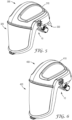
- Fig. 4 is a schematic perspective view of a welding helmet 200 comprising a hard shell 210, a protective visor 220 and a shock absorber assembly 10 according to the present disclosure.
- the shock absorber assembly 10 is only partially visible here (a part of a strap forming the head gear is visible at the rear side of the welding helmet 200) as it is attached to the inside of the hard shell 210.
- Fig. 5 is a schematic perspective view of a respiratory device 300 comprising a hard shell 310, a protective visor 320 and an air supply connection connecting 330 the respiratory device 300 with an air supply unit (not shown here).
- the respiratory device 300 further comprises a shock absorber assembly 10 according to the present disclosure.
- the shock absorber assembly 10 is only partially visible here (a part of a strap forming the head gear is visible at the lower rear side of the respiratory device 300) as it is attached to the inside of the hard shell 310.
- Fig. 6 is a schematic perspective view of a face shield 400 comprising a hard shell 410, a protective visor 420 and a shock absorber assembly 10 according to the present disclosure.
- the shock absorber assembly 10 is only partially visible here (a part of a strap forming the head gear is visible at the lower rear side of the face shield 400) as it is attached to the inside of the hard shell 410.
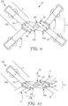
- Fig. 7 is a schematic top view of the deformable element 10a of the shock absorber assembly 10 according to the present disclosure in a non-deformed condition.
- the deformable element 10a has - prior to deformation, i. e. in a non-deformed condition - a width w.
- the straps 16, 17 are only schematically illustrated here as arrows, wherein the strap 16 has two free end portions 16a each with a free end length s (only indicated for one strap 16 here).
- Fig. 7 further illustrates the support distances d1, d2, d3 over which the middle portion 16b (not shown here) of the straps 16 is supported by the deformable element 10a.
- Fig. 8 is a schematic top view of the deformable element 10a of the shock absorber assembly 10 in a deformed condition, e. g. when a load had acted or is acting on the straps 16, 17 such that the free end portions 16a of the strap 16 are pulled away from each other.
- Fig. 8 further illustrates the reduced support distances d1', d2', d3' over which the middle portion 16b of the straps is supported by the deformable element 10a.
- the deformable element 10a has - in the deformed condition - a width w'. Due to the deformation of the deformable element 10a, the width w' is smaller than the width w of the deformable element 10a in the non-deformed condition as illustrated in Fig.
- the straps 16, 17 are only schematically illustrated here as arrows, wherein the strap 16 has two free end portions 16a with a prolonged free end length s' (only one is indicated here). This is because the middle portion 16b of the strap 16 has moved relative to the surface of the deformable element 10a and at least one of the support distances d1', d2', d3', over which the strap 16 is supported on the deformable element 10a, has been decreased. In the example shown, in particular support distance d1' has been decreased in the deformed condition of the deformable element 10a relative to the support distance d1 of the deformable element 10a in the non-deformed condition as shown in Fig. 7 .
- Figs. 9 and 10 are schematic top views of the shock absorber assembly 10 with its deformable element 10a and with two straps 16, 17 arranged on the deformable element 10a such that the middle portion 16b is tightly wrapped around the deformable element 10a.
- the straps 16, 17 each further comprise two free end portions 16a (only one of which is indicated with 16a) having a free end length s as well as two twisted portions 16c.
- Figs. 9 and 10 further show four attachment means 120 (only one of which is indicated with 120) arranged at the free end portion 16a of the strap 16 for attaching the shock absorber assembly 10 to a personal protective equipment, for example a protective helmet, a welding helmet, a face shield or a respiratory device (not shown here).
- Figs. 9 and 10 show the deformable element 10a and the dimensions width w and the support distances d1, d2, d3 in the non-deformed condition ( Fig. 9 ) and the dimensions width w' and the support distances d1', d2', d3' in the deformed condition ( Fig. 10 ) of the deformable element 10a. As can be seen from Figs.
- the width w' and the support distances d1', d2', d3' of Fig. 10 are smaller compared to the width w and the support distances d1, d2, d3 of Fig. 9 .
- the length I of the deformable element 10a in the non-deformed condition may decrease to the length I' of the deformable element 10a in the deformed condition ( Fig. 10 ).
- Figs. 9 and 10 illustrate free end length s of the strap 16 when the deformable element 10a is in a non-deformed condition ( Fig.
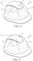
- Figs. 11 and 12 are schematic perspective views of a protective helmet 100 with a shock absorber assembly 10 (in dotted lines as it is arranged inside of the hard shell 110 of the protective helmet 100).
- the shock absorber assembly 10 is arranged such that a distance d occurs between the inner surface of the hard shell 110 and the deformable element 10a of the shock absorber assembly 10, when the deformable element 10a is in the non-deformed condition ( Fig. 11 ).
- Distance d decreases to the distance d' when the deformable element 10a of the shock absorber assembly 10 is in the deformed condition ( Fig. 12 ). This is because the free end length s when the deformable element 10a is in the non-deformed condition ( Fig. 11 ), of one, some or all the straps 16, 17 have been increased, to the free end length s', when the deformable element is in the deformed condition ( Fig. 12 ).
- Fig. 13 is a schematic bottom view of a protective helmet 100 with the shock absorber assembly 10 attached to the inside of the hard shell 110 of the protective helmet 100.
- the free ends 16a of the straps 16, 17 of the shock absorber assembly 10 comprise attachment means 120 which engage with corresponding attachment means 130 of the hard shell 110 of the protective helmet 100.
- Fig. 13 shows the attachment means 120, 130 in the engaged condition.
- the attachment means 120, 130 may provide a release connection to each other such that the shock absorber assembly 10 can be removed from the protective helmet 100, e. g. for replacement by a different shock absorber assembly or another head gear.
- the protective helmet 100 may initially not have had a shock absorber assembly 10 according to the present disclosure.
- the shock absorber assembly 10 may have been retrofitted to the protective helmet 100 by removing the initial assembly, e. g. a standard head gear without shock absorption, by disconnecting its attachment means from the attachment means 130 of the protective helmet 100 and replacing the initial assembly with the shock absorber assembly 10 according to the present disclosure by connecting the attachment means 120 with the corresponding attachment means 130 of the protective helmet 100. It is also conceivable that the connection between the attachment means 120 of the shock absorber assembly 10 and the attachment means 130 of the protective helmet 100 is permanent, i. e. not releasable or disconnectable.
- Fig. 13 further shows details of the deformable element 10a and the straps 16, 17 similar to the shock absorber assembly 10 as shown in Figs. 2 and 9 .
- Figs. 14 and 15 are schematic top views of the deformable element 10a' according to a further embodiment of the shock absorber assembly 10.
- the deformable element 10a' of Figs. 14 and 15 is generally similar to the deformable element 10a as shown in Fig. 1 except that the indicator 30' here is different compared to the indicator 30 as shown on Fig. 1 .
- the indicator 30' is separate from the deformable element 10a' here, whereas the indicator 30 shown in Fig. 1 is integral with the main body 12 of the deformable element 10a.
- the deformable element 10a' as shown here also comprises a main body 12' and an opening 14' formed therein.
- the indicator 30' comprises two protrusions 32a', 32b' into an opening 32' formed within the indicator 30'.
- the two protrusions 32a', 32b' are connected to each other by connection 32c', which is being released upon deformation of the deformable element 10a' (not shown here).
- the indicator 30' further comprises attachment means 34a' for engaging with corresponding attachment means 34b' arranged on the main body 12' of the deformable element 10a' for attaching the indicator 30' to the deformable element 10a'. It is noted that the attachment may be releasable, i. e.
- FIG. 15 shows the indicator 30' attached to the main body 12' of the deformable element 10a' with the attachment means 34a' and 34b' engaged with each other.
- Figs. 14 and 15 show four attachment means 34a', 34b'. Other configurations with more or less attachment means are conceivable as well.
- a further alternative of attachment means is shown below in Figs. 17A, 17B , 18A and 18B . It is noted that the details of the shock absorber assembly 10 as shown above are also conceivable to be present here.
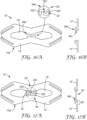
- Figs. 16A and 17A are schematic top views of the deformable element 10a" with alternative attachment means 34" for the indicator 30".
- the indicator 30" is similar in structure and function re. the indicator 30, 30' as shown in Figs. 1 , 14 and 15 above, i. e. the indicator 30" comprises two protrusions 32a", 32b" extending into an opening 32" and connected to each other by a connection 32c". Similar to the above-described indicators 30, 30', the connection 32c" of indicator 30" is being released upon deformation of the deformable element 10a".
- the indicator 30" does not have explicit attachment means arranged thereon except the outer perimeter region 34a" thereof, which is engaged by attachment means 34" of the main body 12" of the deformable element 10a".
- Fig. 16A shows the indicator 30" in a not-attached condition
- Fig. 17A shows the indicator 30" attached to the main body 12" of the deformable element 10a".
- the attachment means 34" with its two legs 34b' forming a gap 34c" therebetween engage the outer perimeter region 34a" of the indicator 30".
- the thickness of the indicator element 30" and the gap 34c" between the two legs 34b" of the attachment means 34" are configured and arranged such that - when the indicator 30" is attached and the outer perimeter region 34a" is introduced into the gap 34c", a tight fit or clamping is provided in order to keep the indicator 30" securely in place.
- Other configurations are conceivable as well, for example an increased friction of the surfaces to enhance the attachment. It is also conceivable to provide an adhesive between the surfaces to further enhance the attachment. Similar to Figs. 1 , 14 and 15 , an opening 14" formed in the main body 12" of the deformable element 10a" is shown here.
- Figs. 16B and 17B illustrate in a schematic side view the main body 12" with the attachment means 34" ( Fig. 16B ) and the engagement of the outer perimeter region of the indicator 30" by the attachment means 34".
- the attachment means 34" has two legs 34b" forming a gap 34c" therebetween for receiving the outer perimeter region 34a"of the indicator 30" ( Fig. 17B ).
- the attachment means 34" and the outer perimeter region 34a" of the indicator 30" are configured and arranged to provide a reliable fit such that the indicator 30" is securely kept in place. It is noted that the attachment may be releasable, i. e. disconnectable, or non-releasable, i. e. permanent or not disconnectable. It is also noted that the details of the shock absorber assembly 10,10' as shown above are also conceivable to be present here.
- Figs. 18A and 18B are schematic top views of the indicator 30' as illustrated above in Fig. 14 and 15 .
- Fig. 18A shows the indicator 30' in a first condition, i. e. prior to the deformation of the deformable element 10a' of the shock absorber assembly 10' (both not shown here), i. e. with the deformable element 10a' in a non-deformed condition.
- the connection 32c' between the two protrusions 32a', 32b' is intact.
- Fig. 18B shows the indicator 30' in a second condition when a deformation of the deformable element 10a' of the shock absorber assembly 10' has happened, i. e.
- connection 32c' has been broken as indicated by the two remaining portions 33a', 33b', which previously had formed the connection 32c'.
- the details of the connection 32c' are illustrated for the separate indicator 30' here, the same applies to other indicators 30, 30", for example an alternative separate indicator 30" as shown in Figs. 16A, 17A or an integrated indicator 30 as shown in Fig. 1 .
- the connection 32c, 32c', 32c which is formed as a bar between the two protrusions 32a, 32b, 32a', 32b', 32a", 32b" and which may be integral with these, may be formed in a different way.
- connection 32c, 32c', 32c" may have a different shape and/or may be a separate part which is attached to the two protrusions 32a, 32b, 32a', 32b', 32a", 32b". Suitable attachment means may be present in such a case. It is noted that the details of the shock absorber assembly 10, 10', 10" as shown above are also conceivable to be present here.
Landscapes
- Helmets And Other Head Coverings (AREA)
Abstract
Description
- The present disclosure relates to a shock absorber assembly for a personal protective equipment comprising a deformable element and to a deformable element for such a shock absorber assembly. The present disclosure furthermore relates to a method of retrofitting such a shock absorber assembly to a personal protective equipment, preferably a protective helmet. The present disclosure moreover relates to a protective helmet, a welding helmet, a face shield or a respiratory device comprising a hard shell and such a shock absorber.
- Personal protective equipment, e. g. protective helmets are commonly worn by people such as firefighters, construction workers, and athletes to shield their heads from flying or falling objects. The helmet usually includes a rigid protective shell or hard shell of impact resistant material. For some applications, the helmets may also include visors or face shields to protect the eyes or the entire face of the wearer, and may further include a respirator to protect the wearer's respiratory system.
- Various government agencies and industry organizations define certain requirements and standards for protective gear, including helmets and respirators. In the United States, for example, the National Institute of Occupational Safety and Health (NIOSH) certifies certain safety equipment for the workplace and the American National Standards Institute (ANSI) recommends voluntary consensus industry standards. Other agencies and organizations around the world also establish safety standards for helmets and respirators. For personal protective equipment, in particular protective helmets, some of these standards relate to impact energy attenuation, penetration resistance, force transmission, stiffness, flammability, and head coverage.
- To meet these safety requirements and standards, protective helmets usually comprise a rigid outer shell or hard shell of metal or plastic and a suspension system inside the shell. The suspension system serves many purposes, including providing a proper fit of the helmet to the wearer's head, holding the inner part of the helmet away from the wearer's head, distributing the weight of the helmet over a larger area of the wearer's head, and attenuating the force transferred to the wearer's head upon impact of an object with the outer helmet shell. Such a force attenuation may also be referred to as shock absorption. Suspension systems often comprise a headband attached to a crown support assembly which includes crisscrossing crown straps and a crown pad. Although providing some shock absorbing properties, there might be situations requiring additional impact protection. However, additional protection may be provided, e. g. by a foam liner between the inner shell and suspension of the helmet to provide additional impact protection. Such solutions may be bulky and may limit the fit of such helmets for certain users.
- It is therefore a need to improve the protection provided by a personal protective equipment, in particular of protective helmets worn by users to protect their head against external impacts. In particular, it is an object of the present disclosure to provide an improved personal protective equipment with regard to external impact protection.
- In a first aspect, the present disclosure relates to a shock absorber assembly for a personal protective equipment. The shock absorber assembly comprises a deformable element exhibiting a mechanical resistance against deformation and a flexible strap comprising a middle portion and two free end portions facing away from each other. The middle portion is tightly wrapped around the deformable element such that pulling the free end portions away from each other deforms the deformable element. Pulling the free end portions away from each other leads to an increase of the length s of at least one of the free end portions upon deformation of the deformable element. The kinetic energy of a falling object is introduced to the personal protective equipment, onto which the object falls. At the impact of the object, the kinetic energy is introduced to the personal protective equipment and is further being transmitted to the straps connected to the hard shell of the personal protective equipment and typically facilitating the wearing of the personal protective equipment on the head of a user or worker. Thus, the impact of the falling object onto the personal protective equipment causes pulling away of the free end portions of the straps. The kinetic energy would normally be transmitted to the user's or worker's head and may cause some impact leading to injuries there. With the shock absorber according to the present disclosure, this energy is being absorbed by the deformation of the deformable element to a greater extent compared to a personal protective equipment without the shock absorber assembly according to the present disclosure. Such an absorption includes a partial reduction as well as an entire absorption of the energy upon deformation of the deformable element. In other words, the impact to the user's head is reduced or attenuated, i. e. the impact time is being extended. It is noted that the straps, in particular the middle portions move relative to the deformable element upon deformation of the deformable element. That is, the strap moves in a sliding manner in the direction of the main extension of the strap. The advantage of such a shock absorber assembly is that a space-saving solution for shock absorption is provided. Also, the shock absorption function can easily be integrated into a headgear of a personal protective equipment, for example a protective helmet, a welding shield, a face shield or a respiratory device.
- Personal protective equipment (PPE) within the meaning of the present disclosure is understood as articles for protective users or workers in a certain environment which may have some negative impact to the user or worker. PPE typically includes wearables like hearing protection, jackets, helmets of different kinds or the like. For the present disclosure, PPE mainly includes protective helmets, welding helmets, face shields or respiratory devices. Such PPE typically comprises a hard shell and is worn on or at the head of a user or worker in order to prevent the user or worker from negative impacts of object falling onto the head of a user or worker, which may cause injuries to the user or worker because of the kinetic energy of a falling object is being transmitted to the user's head without any attenuation or shock absorption otherwise. The hard shell of a PPE may exhibit some rigidity and typically has flexible straps connected to the inside of the hard shell of the personal protective equipment and contacting the user's or worker's head to maintain the position of the PPE on the user's or worker's head. Such straps may form a head gear.
- "Deformation" within the meaning of the present disclosure is understood as an action or a process of deforming or distortion resulting in a change in size or shape of an object. According to this disclosure, an object is in a non-deformed condition prior to the deformation, i. e. not showing a change in size or shape, whereas a deformed condition refers to an object being deformed, i. e. having a changed size and/or shape. Such change may apply to the object as a whole or just to parts of the object. Kinetic energy introduced to the deformable element by the straps of the personal protective equipment, e. g. a protective helmet, onto which an object is falling, may introduce forces - through the hard shell and the straps connected thereto - to the deformable element causing its deformation. Upon deformation, kinetic energy is being absorbed by the change of the object's size and/or shape such that the applying energy is reduced or eliminated and does not provide negative impacts to the user's or worker's head anymore. Deformation typically includes elastic or plastic deformation. Elastic deformation is substantially reversible and the deformed element substantially returns after the deformation to its original size and shape prior to deformation. Such a deformation is also referred to as temporary or non-permanent deformation. An elastic deformation may be achieved through the use of a resilient material. In contrast thereto, plastic deformation means that the deformation is irreversible and that the deformed element does not return after the deformation to its original size and/or shape prior to deformation. The plastic deformation is also referred to as permanent deformation. A plastic deformation may be achieved through the use of a brittle material. It is noted that even in case of an elastic deformation, some plastic deformation may occur in parallel or vice versa.
- "Mechanical resistance against deformation" within the meaning of the present disclosure is understood as a behavior that an object or element, here a part of the personal protective equipment, exhibits under influence of mechanical forces, i. e. forces acting upon the object or element e. g. when a deformation occurs. In particular, the object or element has the behavior to withstand the mechanical forces to some extent. An absorption of the impacting energy happens partially or entirely.
- "Supported" within the meaning of the present disclosure means that the strap is laid onto the surface of the deformable element and is moveable or slidable relative to the surface of the deformable element. Supported does not include a fixed connection between the strap and the deformable element.
- "Movable" or "slidable" within the meaning of the present disclosure means that a point on the strap is displaced relative to a point on the surface of the deformable element. In particular, the strap moves or slides in a direction of the main extension of the strap.
- "Wrapped tightly" within the meaning of the present disclosure means that the middle portion of the strap is arranged around the deformable element such that no loose or hanging portions or hanging or sagging loops of the straps are created. In other words, the strap is in intimate contact to the surface of the deformable element.
- "Shock" within the meaning of the present disclosure is understood as an impact introduced in a short period of time. "Shock absorption" is understood as a delay of that time period leading to an attenuation of the impact.
- In a second aspect, the present disclosure relates to a deformable element for a shock absorber assembly for a personal protective equipment. The deformable element exhibits a mechanical resistance against deformation, wherein the deformable element is configured and arranged to support a middle portion of a strap of a personal protective equipment such that - when the strap is tightly wrapped around the deformable element - pulling the end portions of the strap away from each other deforms the deformable element. The deformable element can preferably be brought from a non-deformed condition with the length I, the thickness t, the width w and the support distances d1, d2, d3 to a deformed condition with the length I', the thickness T', the width w' and the support distances d1', d2', d3', such that the length I' is smaller than length I, the width w' is smaller than the width w, the support distance d1' is smaller than the support distance d1, the support distance d2' is smaller than the support distance d2 and/or the support distance d3' is smaller than the support distance d3. The advantage of such a shock absorber assembly is that a space-saving solution for shock absorption is provided. Also, the shock absorption function can easily be integrated into a headgear of a personal protective equipment, for example a protective helmet, a welding shield, a face shield or a respiratory device.
- In a third aspect, the present disclosure relates to a protective helmet, a welding helmet, a face shield or a respiratory device comprising a hard shell and a shock absorber assembly according to the present disclosure, wherein the hard shell of the protective helmet comprises attachment means for connecting the strap of the shock absorber to the hard shell. The advantage of a protective helmet, a welding helmet, a face shield or a respiratory device with such a shock absorber assembly is that a space-saving solution for shock absorption is provided. Other advantages are listed above for the shock absorber assembly.
- In a fourth aspect, the present disclosure relates to a method of retrofitting a shock absorber assembly according to the present disclosure to a personal protective equipment, preferably a protective helmet. The method comprises the steps of: providing a personal protective equipment, preferably a protective helmet, comprising a strap assembly, preferably a headgear; providing a shock absorber assembly according to the present disclosure; removing the strap assembly from the personal protective equipment and mounting the shock absorber assembly on the personal protective equipment. Such a method of retrofitting is beneficial as a standard personal protective equipment, for example a protective helmet, a welding helmet, a face shield or a respiratory device, can easily and reliably be equipped with a shock absorber function, which was not present in that personal protective equipment beforehand. An increase of safety for the user of the personal protective equipment may be achieved thereby. Other advantages are listed above for the shock absorber assembly.
- In one embodiment, the deformable element of the shock absorber assembly exhibits an elongated shape having a length I, a width w perpendicular to the length I, a thickness t perpendicular to the length I and the width w and support distances d1, d2, d3 arranged on the deformable element for supporting the strap. The deformable element of the shock absorber assembly can be brought from a non-deformed condition with the length I, the thickness t, the width w and the support distances d1, d2, d3 to a deformed condition with the length I', the thickness t', the width w' and the support distances d1', d2', d3', such that the length I' is smaller than length I, the width w' is smaller than the width w, the distance d1' is smaller than the distance d1, the distance d2' is smaller than the distance d2 and/or the distance d3' is smaller than the distance d3. Such an arrangement is beneficial as the change of the dimensions length, width or the support distances may provide for a sufficient and controlled deformation and thus of a sufficient and controlled extension of the free end portions of the strap. Other advantages are listed above for the shock absorber assembly. The length of such a deformable element is greater than the width, for example the length may be 2-times, 3-times or 4-times of the width. Such an elongated shape is beneficial as it provides for an efficient use of the space available in a personal protective equipment, for example a protective helmet, a welding shield, a face shield or a respiratory device. Also, due to the elongated shape, sufficient space is provided on the deformable element such that the strap can reliably be wrapped around in a tight manner and with more than one winding.
- In a further embodiment, the deformable element of the shock absorber assembly comprises a main body and an opening formed therein, wherein the main body and/or the opening are deformed upon deformation of the deformable element. The arrangement of an opening formed within the main body of the deformable element provides for a reliable and sufficient deformation of the deformable element when pulling the free end portions away from each other. The opening may undergo a reduction of size and/or an alteration of shape which facilitates a sufficient deformation of the deformable element.
- In one embodiment, the length I of the deformable element of the shock absorber assembly decreases upon deformation of the deformable element. Such a deformable element is beneficial as it provides for a reliable and sufficient deformation of the deformable element when pulling the free end portions away from each other.
- In a further embodiment, the width w of the deformable element of the shock absorber assembly decreases upon deformation of the deformable element. Such a deformable element is beneficial as it provides for a reliable and sufficient deformation of the deformable element when pulling the free end portions away from each other.
- In a further embodiment, the thickness t of the deformable element of the shock absorber assembly decreases upon deformation of the deformable element. Such a deformable element is beneficial as it provides for a reliable and sufficient deformation of the deformable element when pulling the free end portions away from each other.
- In yet a further embodiment, at least one of the support distances d1, d2, d3 of the deformable element of the shock absorber assembly decreases upon deformation of the deformable element. Such a deformable element is beneficial as it provides for a reliable and sufficient deformation of the deformable element when pulling the free end portions away from each other.
- It is conceivable that the deformable element is configured and arranged such that one, several or all the dimensions, for example the length I, the width w and/or the support distances d1, d2, d3 decrease upon deformation. Such a deformable element is beneficial as it provides for a reliable and sufficient deformation of the deformable element when pulling the free end portions away from each other.
- In one embodiment, the middle portion of the strap is supported by the deformable element of the shock absorber assembly. Such an arrangement is of advantage as the strap is reliably and securely arranged at the deformable element thereby.
- In another embodiment, the two free end portions of the strap each protrude from the deformable element of the shock absorber assembly. Such an arrangement provides for some design variations within the personal protective equipment, e. g. a protective helmet, as the protruding portions provide for a good fit of the personal protective equipment with such a shock absorber assembly onto the user's or worker's head.
- In a further embodiment, the strap of the shock absorber assembly exhibits a tensile strength of 1200 to 1800 N. Such a tensile strength of the strap provides for a reliable and secure personal protective equipment.
- In another embodiment, the strap and the deformable element of the shock absorber assembly form a head gear. Such an assembly is of advantage as the shock absorber assembly can replace the head gear of a personal protective equipment, for example a protective helmet, a welding helmet, a face shield or a respiratory device, and provide for a shock absorber function of such a personal protective equipment originally not having that function. In other words, such a head gear with a shock absorber according to the present disclosure can easily be retrofitted to an existing personal protective equipment, for example of the type as mentioned above as the original head gear can be removed and be replaced by such a head gear according to the present disclosure at once or as a whole.
- In one embodiment, the deformable element of the shock absorber assembly comprises strap guiding means for guiding the strap at the deformable element, wherein the strap guiding means preferably comprises a guiding arm arranged such that a slot for receiving the strap is formed between the guiding arm and the main body of the deformable element. Such a guiding arm and such a slot may be formed such that the slot is open on one end thereof. It is also conceivable that the slot is closed on both ends. The guiding arm may protrude from the perimeter of the deformable element or may protrude from the major surface of the deformable element. A strap guiding means is of advantage as guiding of the strap on the deformable element provides for a reliable and secure assembly. An unwanted movement of the strap, for example in a direction transverse to the main extension of the strap, is prevented thereby while still allowing for movement in the main extension direction of the strap, which is required for the function of the shock absorber assembly.
- In another embodiment, the strap of the shock absorber assembly is made of a woven textile. Such a structure has the advantage that the strap exhibits the required properties with regard to tensile strength, flexibility and manufacturing costs.
- In another embodiment, the strap of the shock absorber assembly comprises polypropylene, polyester or polyamide. Such a material has the advantage that the strap exhibits the required properties with regard to tensile strength, flexibility and manufacturing costs.
- In yet another embodiment, the strap of the shock absorber assembly comprises a twisted portion when wrapped around the deformable element such that the strap exhibits a 180 degrees twist at the deformable element, wherein the strap preferably comprises two twisted portions. As a result of the twisted portion, the strap turns from a first major surface of the deformable element to a second major surface of the deformable element. Such an arrangement with a twisted portion provides for a strap which has a sufficient length of the middle portion wrapped around the deformable element. A sufficient increase of the length of the free end portions of the strap protruding from the deformable element is achieved thereby as more than one layer of the strap on the deformable element can move.
- In still another embodiment, the shock absorber assembly comprises two flexible straps each comprising a middle portion and two free end portions facing away from each other. The middle portion is tightly wrapped around the deformable element such that pulling the free end portions away from each other deforms the deformable element. The middle portions of the two straps at least partially overlap with each other. The advantage of such an assembly with two straps is that a good fit of the personal protective equipment is provided when worn by a user.
- In one embodiment, the deformable element of the shock absorber assembly comprises a resilient material and wherein the deformation of the deformable element is reversible. Such a resilient material for the deformable element is beneficial as the deformable element may return to its original shape after release of the load, which may provide for a re-usable shock absorber assembly.
- In a certain embodiment, the resilient material of the deformable element of the shock absorber assembly is selected from polycarbonate, polyethylene, preferably high-density polyethylene, acrylonitrile-butadiene-styrene. Such a material is advantageous because it provides for reliable properties of the deformable element regarding the deformation and the return to the original shape.
- In one embodiment, the deformable element of the shock absorber assembly comprises a brittle material and wherein the deformation of the deformable element is irreversible. Such a brittle material facilitates an irreversible deformation of the deformable element. This may be useful to provide an indicator function to the user of the personal protective equipment, i. e. an indication to the user that the deformable element has been deformed. Also, an unwanted re-use of the shock absorber assembly may be prevented thereby.
- In a certain embodiment, the brittle material of the deformable element of the shock absorber assembly is selected from polystyrene, polyvinyl chloride, acrylic materials. Such a material is advantageous because it provides for reliable properties of the deformable element regarding deformation and further supports the indication function to the user about a load acting on the strap.
- In another embodiment, the thickness t of the deformable element of the shock absorber assembly is in the range of 0,1 to 5 mm in a non-deformed condition. Such a thickness is of advantage as it provides for a space-saving arrangement of the deformable element within a personal protective equipment, for example a protective helmet, on the one hand and for a reliable and stable design of the deformable element on the other hand.
- In one embodiment, the shock absorber assembly comprises an indicator for indicating a deformation of the deformable element. Such an indicator is of advantage as it provides for a reliable indication - independent of the optical appearance of the deformable element - of a deformation of the deformable element which has happened upon acting of a load on the personal protective equipment. In other words, even if the deformation of the deformable element is not visible to the user (any longer), e. g. a deformable element which is elastically deformable and the deformation of the deformable element is reversible, respectively, there is an indication to the user of a deformation that has happened. In some countries, personal protective equipment may underlie regulatory aspects and such a regulation may require that there is a reliable indication about a shock absorber that has been activated.
- In a certain embodiment, the indicator of the shock absorber assembly has a load threshold value for the load impact and wherein the indicator indicates the load impacting onto the deformable element above the load threshold, wherein the load threshold value is preferably between 500 N and 10 kN. It is noted that there may specific values be set for specific personal protective equipment depending on demand in the geographic area. Such a load threshold value is of advantage as the indicator does not indicate low impacts, i. e. impacts of a low load which may be considered uncritical. An indication provided by such an indicator means that the load was reasonably high and therefore it is important that the user is being informed about that.
- In certain embodiments, the indication of the indicator of the shock absorber assembly is irreversible. That means that the indicator undergoes a shape, size and/or appearance change which irreversibly indicates a deformation of the deformable element of the shock absorber assembly to which the indicator belongs or to which the indicator is attached to. Such an indicator is beneficial as the indication is permanently observable even if the deformable element is elastically deformable and returns to its shape and appearance after the load impact. Such an irreversible indicator may comprise an ink or a paint arranged on the surface of the deformable element, wherein the ink or paint exhibits optical defects after a load impact, e. g. cracks. It is also conceivable that the indicator comprises a mechanical indicator element, e. g. a thread or other thin structure which ruptures when a load impacted on the shock absorber.
- In certain embodiments, the indicator of the shock absorber assembly is attachable to the deformable element. Such an attachable indicator has the advantage that it can be replaced after indication and the deformable element is still usable with a new indicator. This is particularly useful if the deformable element is elastically deformable and the deformation is reversible. Also, the indicator may be replaced by another one, i. e. an indicator with different properties, e. g. different sensitivity. The shock absorber assembly and/or the indicator may comprise attachment means for attaching the indicator to the deformable element of the shock absorber assembly. The attachment means may comprise a mechanical attachment means such as mechanical fasteners, snap fit or the like, an adhesive attachment means such as an adhesive layer or a combination thereof. The advantage of such an attachment means is that an easy and reliable way of attaching the indicator to the deformable element of the shock absorber is provided thereby.
- In a certain embodiment, the indicator of the shock absorber assembly is integral with the deformable element. For example, the indicator is formed as a protrusion of an edge of the deformable element, which may protrude from the edge into an opening present at the deformable element of the shock absorber assembly. Other arrangements are conceivable as well, for example an indicator arranged on the surface of the deformable element or protruding from an outer edge of the deformable element. Such an integral indicator has the advantage that no attachment means are required. Also, an easy, compact and robust arrangement of the indicator is provided thereby. Furthermore, an unwanted replacement of the indicator is prohibited thereby, which may in particular be required by regulations.
- In one embodiment of the method of retrofitting a shock absorber assembly according to the present disclosure to a personal protective equipment, the personal protective equipment is a protective helmet, a welding helmet, a face shield or a respiratory device. Such a method of retrofitting is beneficial as a standard personal protective equipment, for example a protective helmet, a welding helmet, a face shield or a respiratory device, can easily and reliably be equipped with a shock absorber function, which was not present in that personal protective equipment beforehand. In particular, retrofitting the shock absorber assembly to a protective helmet, a welding shield, a face shield or a respiratory device provides an increased level of safety for such personal protective equipment.
- The invention was described in various embodiments above. It is understood by a person skilled in the art, that one of, several of or all the above-mentioned embodiments can be combined with each other.
- The invention will now be described in more detail with reference to the following Figures exemplifying particular embodiments of the invention:
-
-
Fig. 1 is a schematic top view of an embodiment of the deformable element of the shock absorber assembly according to the present disclosure; -
Fig. 2 is a schematic top view of an embodiment of the shock absorber assembly according to the present disclosure with two flexible straps assembled to the deformable element; -
Fig. 3 is a schematic perspective view of a protective helmet with the shock absorber assembly according to the present disclosure; -
Fig. 4 is a schematic perspective view of a welding helmet with the shock absorber assembly according to the present disclosure; -
Fig. 5 is a schematic perspective view of a respiratory device with the shock absorber assembly according to the present disclosure; -
Fig. 6 is a schematic perspective view of a face shield with the shock absorber assembly according to the present disclosure; -
Fig. 7 is a schematic top view of the deformable element of the shock absorber assembly as shown inFig. 1 with the deformable element being in a non-deformed condition; -
Fig. 8 is a schematic top view of the deformable element of the shock absorber assembly as shown inFig. 1 with the deformable element being in a deformed condition; -
Fig. 9 is a schematic top view of the shock absorber assembly assembled with two flexible straps as shown inFig. 2 with the deformable element being in a non-deformed condition; -
Fig. 10 is a schematic top view of the shock absorber assembly assembled with two flexible straps as shown inFig. 2 with the deformable element being in a deformed condition; -
Fig. 11 is a schematic perspective view of a protective helmet with the shock absorber assembly according to the present disclosure with the deformable element being in a non-deformed condition; -
Fig. 12 is a schematic perspective view of a protective helmet with the shock absorber assembly according to the present disclosure with the deformable element being in a deformed condition; -
Fig. 13 is a schematic bottom view of a protective helmet with the shock absorber assembly according to the present disclosure with the flexible straps attached to the hard shell of the protective helmet; -
Fig. 14 is a schematic top view of the deformable element of the shock absorber assembly according to another embodiment and an indicator attachable thereto; -
Fig. 15 is a schematic top view of the deformable element of the shock absorber assembly as shown inFig. 14 with the indicator attached thereto; -
Fig. 16A is a schematic top view of the deformable element of the shock absorber assembly according to another embodiment and an indicator attachable thereto; -
Fig. 16B is a cross-sectional view of the deformable element of the shock absorber assembly as shown inFig. 16A ; -
Fig. 17A is a schematic top view of the deformable element of the shock absorber assembly as shown inFig. 14 with the indicator attached thereto; -
Fig. 17B is a cross-sectional view of the deformable element of the shock absorber assembly as shown inFig. 17A ; -
Fig. 18A is a schematic top view of the indicator of the shock absorber assembly according to an embodiment of the present disclosure as shown inFigs. 14 and 15 , in a first condition and -
Fig. 18B is a schematic top view of the indicator of the shock absorber assembly according to an embodiment of the present disclosure as shown inFigs. 14 and 15 , in a second condition. -
Figure 1 is a schematic top view of an embodiment of thedeformable element 10a of theshock absorber assembly 10 according to the present disclosure. Theshock absorber assembly 10 comprises adeformable element 10a having an elongated shape with a length I and a width w perpendicular to the length I. In the embodiment shown, the length I is approximately 3 times of the width w. Although not shown here, other configurations are conceivable with a different length-to-width ratio. Thedeformable element 10a of theshock absorber assembly 10 comprises amain body 12 and anopening 14 formed therein. Theopening 14 may be formed by cutting out or punching the material of themain body 12. Alternatively, themain body 12 may be formed in a molding process, e. g. an injection molding process, wherein theopening 14 is directly formed together with themain body 12 in such a process. Upon deformation of thedeformable element 10a, themain body 12 and/or theopening 14 will change their shape and appearance (not shown inFig. 1 , seeFigs. 7 and 8 orFigs. 9 and 10 ). Theshock absorber assembly 10 further comprises twoflexible straps Fig. 2 ). At the upper and lower perimeter of thedeformable element 10a, towards the transverse sides of thedeformable element 10a, strap guiding means 20 are arranged for guiding thestraps 16, 17 (not shown) at thedeformable element 10a. The strap guiding means 20 are explained in more detail below inFig. 2 . Thedeformable element 10a of theshock absorber assembly 10 as shown further comprises anindicator 30 for indicating a deformation of thedeformable element 10a that has happened. As can be seen, theindicator 30 comprises twoprotrusions deformable element 10a into theopening 14. Theprotrusions connection 32c. A deformation of thedeformable element 10a will lead to a movement of theprotrusions connection 32c therebetween is released, e. g. by breaking. Such a release can be observed, e. g. optically, by a user. Thedeformable element 10a also shows afurther indicator 36, which may be arranged in addition to theindicator 30 or as an alternative thereto. In the example shown, theindicator 36 comprises an ink or paint which is arranged on the surface of thedeformable element 10a. A deformation of thedeformable element 10a leads to damage of the surface of the ink or paint such that cracks or the like occur. Theindicator 36 in the example shown exhibits cracks 38 which occurred upon a deformation thedeformable element 10a did undergo.Such cracks 38 can be observed, e. g. optically, by a user. -
Figure 2 is a schematic top view of an embodiment of theshock absorber assembly 10 according to the present disclosure. Similar toFig. 1 , theshock absorber assembly 10 comprises adeformable element 10a and has an elongated extension. Thedeformable element 10a comprises amain body 12 and anopening 14 formed therein. In addition to what is shown inFig. 1 , theshock absorber assembly 10 further comprises twoflexible straps middle portion 16b which is tightly wrapped around thedeformable element 10a and twofree end portions 16a facing away from each other. Themiddle portion 16b of thestraps deformable element 10a. A part of themiddle portion 16b of thestrap 16 is on a first major surface of thedeformable element 10a. Thestrap 16 further comprises twotwisted portions 16c at which thestrap 16 turns from a first major surface of thedeformable element 10a to a second major surface opposite to the first major surface such that a part of the middle portion of the strap is on the opposite second major surface (underneath thedeformable element 10a and thus not visible here) and vice versa. Although twotwisted portions 16c are indicated inFig. 2 , it is noted that there may be more than twotwisted portions 16c present at thestraps strap 16 around thedeformable elements 10a when tightly wrapping thestrap 16 around thedeformable element 10a. In the example shown inFig. 2 , there are twostraps middle portion 16b tightly wrapped around thedeformable element 10a. As can be seen, themiddle portions 16b of the twostraps Fig. 2 the top side) of thedeformable element 10a and one time on the second major surface thereof (inFig. 2 the rear side, thus not visible here). Other configurations are conceivable, e. g. having more or less overlaps of themiddle portions 16b of thestraps free end portions 16a of astrap 16 away from each other deforms thedeformable element 10a (deformation not shown here, seeFigs. 7 and 8 or9 and 10 ). Thefree end portions 16a of thestraps deformable element 10a. Thefree end portion 16a is not supported by thedeformable element 10a. Upon deformation of thedeformable element 10a, themiddle portion 16b of thestraps deformable element 10a in a direction along the extension of thestrap 16. In other words, themiddle portion 16b slides on the surface of thedeformable element 10a such that the length s of thefree end portion 16a protruding from thedeformable element 10a increases to the free length s' (not shown here, seeFigs. 9 and 10 ). Similar toFig. 1 , thedeformable element 10a comprises strap guiding means 20 which is formed by a guidingarm 22 defining aslot 24 for receiving thestrap 16. As shown, thestrap 16 extends through theslot 24 and is kept in place by the guidingarm 22. It is noted that the contact between the guidingarm 22 and thestrap 16 is tight, but not so strong that a movement of the strap through theslot 24 of the guiding means 20 is substantially inhibited. Such a strap guiding means 20 with its guidingarm 22 may be formed by cutting out a portion of themain body 12 of thedeformable element 10a to form theslot 24 and thereby the guidingarm 22. It is also conceivable to make the strap guiding means 20 by a molding process, e. g. an injection molding process, preferably at the same time when themain body 12 of thedeformable element 10a is formed. -
Fig. 3 is a schematic perspective view of aprotective helmet 100 comprising ahard shell 110 and ashock absorber assembly 10 according to the present disclosure. - The
shock absorber assembly 10 is only partially visible here (a part of a strap forming the head gear is visible at the rear side of the protective helmet 100) as it is attached to the inside of thehard shell 110. -
Fig. 4 is a schematic perspective view of awelding helmet 200 comprising ahard shell 210, aprotective visor 220 and ashock absorber assembly 10 according to the present disclosure. Theshock absorber assembly 10 is only partially visible here (a part of a strap forming the head gear is visible at the rear side of the welding helmet 200) as it is attached to the inside of thehard shell 210. -
Fig. 5 is a schematic perspective view of arespiratory device 300 comprising ahard shell 310, aprotective visor 320 and an air supply connection connecting 330 therespiratory device 300 with an air supply unit (not shown here). Therespiratory device 300 further comprises ashock absorber assembly 10 according to the present disclosure. Theshock absorber assembly 10 is only partially visible here (a part of a strap forming the head gear is visible at the lower rear side of the respiratory device 300) as it is attached to the inside of thehard shell 310. -
Fig. 6 is a schematic perspective view of aface shield 400 comprising ahard shell 410, aprotective visor 420 and ashock absorber assembly 10 according to the present disclosure. Theshock absorber assembly 10 is only partially visible here (a part of a strap forming the head gear is visible at the lower rear side of the face shield 400) as it is attached to the inside of thehard shell 410. -
Fig. 7 is a schematic top view of thedeformable element 10a of theshock absorber assembly 10 according to the present disclosure in a non-deformed condition. Thedeformable element 10a has - prior to deformation, i. e. in a non-deformed condition - a width w. Thestraps strap 16 has twofree end portions 16a each with a free end length s (only indicated for onestrap 16 here).Fig. 7 further illustrates the support distances d1, d2, d3 over which themiddle portion 16b (not shown here) of thestraps 16 is supported by thedeformable element 10a. -
Fig. 8 is a schematic top view of thedeformable element 10a of theshock absorber assembly 10 in a deformed condition, e. g. when a load had acted or is acting on thestraps free end portions 16a of thestrap 16 are pulled away from each other.Fig. 8 further illustrates the reduced support distances d1', d2', d3' over which themiddle portion 16b of the straps is supported by thedeformable element 10a. Thedeformable element 10a has - in the deformed condition - a width w'. Due to the deformation of thedeformable element 10a, the width w' is smaller than the width w of thedeformable element 10a in the non-deformed condition as illustrated inFig. 7 above. Thestraps strap 16 has twofree end portions 16a with a prolonged free end length s' (only one is indicated here). This is because themiddle portion 16b of thestrap 16 has moved relative to the surface of thedeformable element 10a and at least one of the support distances d1', d2', d3', over which thestrap 16 is supported on thedeformable element 10a, has been decreased. In the example shown, in particular support distance d1' has been decreased in the deformed condition of thedeformable element 10a relative to the support distance d1 of thedeformable element 10a in the non-deformed condition as shown inFig. 7 . This leads to an increase in length s' compared to the length s inFig. 7 . Although not illustrated here, other dimensions may also be decreased, e. g. the length I' or the support distances d2', d3' relative to the length I or the support distances d2, d3 as shown onFig. 7 , at the same time. -
Figs. 9 and 10 are schematic top views of theshock absorber assembly 10 with itsdeformable element 10a and with twostraps deformable element 10a such that themiddle portion 16b is tightly wrapped around thedeformable element 10a. As can be seen, thestraps free end portions 16a (only one of which is indicated with 16a) having a free end length s as well as twotwisted portions 16c.Figs. 9 and 10 further show four attachment means 120 (only one of which is indicated with 120) arranged at thefree end portion 16a of thestrap 16 for attaching theshock absorber assembly 10 to a personal protective equipment, for example a protective helmet, a welding helmet, a face shield or a respiratory device (not shown here). It is understood, although not shown, that all thefree end portions 16a of thestraps protective helmet 100 as shown inFig. 13 . Similar toFigs. 7 and 8 ,Figs. 9 and 10 show thedeformable element 10a and the dimensions width w and the support distances d1, d2, d3 in the non-deformed condition (Fig. 9 ) and the dimensions width w' and the support distances d1', d2', d3' in the deformed condition (Fig. 10 ) of thedeformable element 10a. As can be seen fromFigs. 9 and 10 , the width w' and the support distances d1', d2', d3' ofFig. 10 are smaller compared to the width w and the support distances d1, d2, d3 ofFig. 9 . Although not illustrated inFigs. 9 and 10 , also the length I of thedeformable element 10a in the non-deformed condition (Fig. 9 ) may decrease to the length I' of thedeformable element 10a in the deformed condition (Fig. 10 ). Similar toFigs. 7 and 8 ,Figs. 9 and 10 illustrate free end length s of thestrap 16 when thedeformable element 10a is in a non-deformed condition (Fig. 9 ) which increases to the free end length s' of thestrap 16 when thedeformable element 10a is in a deformed condition (Fig. 10 ). It is noted that - although such an arrangement is only illustrated for onefree end 16a of the strap 16 - the other free ends may similarly exhibit an increased free end length s' of thefree end portion 16 of thestraps deformable element 10a is in the deformed condition relative to the free end length s of thefree end portion 16a of thestraps deformable element 10a is in the non-deformed condition. -
Figs. 11 and 12 are schematic perspective views of aprotective helmet 100 with a shock absorber assembly 10 (in dotted lines as it is arranged inside of thehard shell 110 of the protective helmet 100). As can be seen, theshock absorber assembly 10 is arranged such that a distance d occurs between the inner surface of thehard shell 110 and thedeformable element 10a of theshock absorber assembly 10, when thedeformable element 10a is in the non-deformed condition (Fig. 11 ). Distance d decreases to the distance d' when thedeformable element 10a of theshock absorber assembly 10 is in the deformed condition (Fig. 12 ). This is because the free end length s when thedeformable element 10a is in the non-deformed condition (Fig. 11 ), of one, some or all thestraps Fig. 12 ). -
Fig. 13 is a schematic bottom view of aprotective helmet 100 with theshock absorber assembly 10 attached to the inside of thehard shell 110 of theprotective helmet 100. As can be seen, the free ends 16a of thestraps shock absorber assembly 10 comprise attachment means 120 which engage with corresponding attachment means 130 of thehard shell 110 of theprotective helmet 100.Fig. 13 shows the attachment means 120, 130 in the engaged condition. It is noted that the attachment means 120, 130 may provide a release connection to each other such that theshock absorber assembly 10 can be removed from theprotective helmet 100, e. g. for replacement by a different shock absorber assembly or another head gear. It is also noted that theprotective helmet 100 may initially not have had ashock absorber assembly 10 according to the present disclosure. Due to the releasable attachment means 130, theshock absorber assembly 10 may have been retrofitted to theprotective helmet 100 by removing the initial assembly, e. g. a standard head gear without shock absorption, by disconnecting its attachment means from the attachment means 130 of theprotective helmet 100 and replacing the initial assembly with theshock absorber assembly 10 according to the present disclosure by connecting the attachment means 120 with the corresponding attachment means 130 of theprotective helmet 100. It is also conceivable that the connection between the attachment means 120 of theshock absorber assembly 10 and the attachment means 130 of theprotective helmet 100 is permanent, i. e. not releasable or disconnectable.Fig. 13 further shows details of thedeformable element 10a and thestraps shock absorber assembly 10 as shown inFigs. 2 and9 . -
Figs. 14 and 15 are schematic top views of thedeformable element 10a' according to a further embodiment of theshock absorber assembly 10. Thedeformable element 10a' ofFigs. 14 and 15 is generally similar to thedeformable element 10a as shown inFig. 1 except that the indicator 30' here is different compared to theindicator 30 as shown onFig. 1 . The indicator 30' is separate from thedeformable element 10a' here, whereas theindicator 30 shown inFig. 1 is integral with themain body 12 of thedeformable element 10a. Thedeformable element 10a' as shown here also comprises a main body 12' and an opening 14' formed therein. Shape and function of the main body 12' and the opening 14' as shown here is similar to themain body 12 and theopening 14 as shown inFig. 14 . The indicator 30' comprises twoprotrusions 32a', 32b' into an opening 32' formed within the indicator 30'. The twoprotrusions 32a', 32b' are connected to each other byconnection 32c', which is being released upon deformation of thedeformable element 10a' (not shown here). The indicator 30' further comprises attachment means 34a' for engaging with corresponding attachment means 34b' arranged on the main body 12' of thedeformable element 10a' for attaching the indicator 30' to thedeformable element 10a'. It is noted that the attachment may be releasable, i. e. disconnectable, or non-releasable, i. e. permanent or not disconnectable.Fig. 15 shows the indicator 30' attached to the main body 12' of thedeformable element 10a' with the attachment means 34a' and 34b' engaged with each other.Figs. 14 and 15 show four attachment means 34a', 34b'. Other configurations with more or less attachment means are conceivable as well. A further alternative of attachment means is shown below inFigs. 17A, 17B ,18A and 18B . It is noted that the details of theshock absorber assembly 10 as shown above are also conceivable to be present here. -
Figs. 16A and 17A are schematic top views of thedeformable element 10a" with alternative attachment means 34" for theindicator 30". Theindicator 30" is similar in structure and function re. theindicator 30, 30' as shown inFigs. 1 ,14 and 15 above, i. e. theindicator 30" comprises twoprotrusions 32a", 32b" extending into anopening 32" and connected to each other by aconnection 32c". Similar to the above-describedindicators 30, 30', theconnection 32c" ofindicator 30" is being released upon deformation of thedeformable element 10a". As can be seen, theindicator 30" does not have explicit attachment means arranged thereon except theouter perimeter region 34a" thereof, which is engaged by attachment means 34" of themain body 12" of thedeformable element 10a".Fig. 16A shows theindicator 30" in a not-attached condition, whereasFig. 17A shows theindicator 30" attached to themain body 12" of thedeformable element 10a". In this attached condition, the attachment means 34" with its twolegs 34b' forming agap 34c" therebetween engage theouter perimeter region 34a" of theindicator 30". It is noted that the thickness of theindicator element 30" and thegap 34c" between the twolegs 34b" of the attachment means 34" are configured and arranged such that - when theindicator 30" is attached and theouter perimeter region 34a" is introduced into thegap 34c", a tight fit or clamping is provided in order to keep theindicator 30" securely in place. Other configurations are conceivable as well, for example an increased friction of the surfaces to enhance the attachment. It is also conceivable to provide an adhesive between the surfaces to further enhance the attachment. Similar toFigs. 1 ,14 and 15 , anopening 14" formed in themain body 12" of thedeformable element 10a" is shown here. Shape and function of themain body 12" and theopening 14" as shown here is similar to themain body 12, 12' and theopening 14, 14' of thedeformable elements Fig. 1 ,14 and15 .Figs. 16B and 17B illustrate in a schematic side view themain body 12" with the attachment means 34" (Fig. 16B ) and the engagement of the outer perimeter region of theindicator 30" by the attachment means 34". As can be seen, the attachment means 34" has twolegs 34b" forming agap 34c" therebetween for receiving theouter perimeter region 34a"of theindicator 30" (Fig. 17B ). As mentioned above, the attachment means 34" and theouter perimeter region 34a" of theindicator 30" are configured and arranged to provide a reliable fit such that theindicator 30" is securely kept in place. It is noted that the attachment may be releasable, i. e. disconnectable, or non-releasable, i. e. permanent or not disconnectable. It is also noted that the details of theshock absorber assembly 10,10' as shown above are also conceivable to be present here. -
Figs. 18A and 18B are schematic top views of the indicator 30' as illustrated above inFig. 14 and 15 .Fig. 18A shows the indicator 30' in a first condition, i. e. prior to the deformation of thedeformable element 10a' of the shock absorber assembly 10' (both not shown here), i. e. with thedeformable element 10a' in a non-deformed condition. As can be seen, theconnection 32c' between the twoprotrusions 32a', 32b' is intact.Fig. 18B shows the indicator 30' in a second condition when a deformation of thedeformable element 10a' of the shock absorber assembly 10' has happened, i. e. with thedeformable element 10a' in a deformed condition. Here, theconnection 32c' has been broken as indicated by the two remainingportions 33a', 33b', which previously had formed theconnection 32c'. Although the details of theconnection 32c' are illustrated for the separate indicator 30' here, the same applies toother indicators separate indicator 30" as shown inFigs. 16A, 17A or anintegrated indicator 30 as shown inFig. 1 . It is further noted that theconnection protrusions connection protrusions shock absorber assembly
Claims (15)
- A shock absorber assembly (10, 10', 10") for a personal protective equipment, the shock absorber assembly (10, 10', 10") comprising• a deformable element (10a, 10a', 10a") exhibiting a mechanical resistance against deformation and• a flexible strap (16, 17) comprising a middle portion (16b) and two free end portions (16a) facing away from each other, wherein the middle portion (16b) is tightly wrapped around the deformable element (10a, 10a', 10a") such that pulling the free end portions (16a) away from each other deforms the deformable element (10a, 10a', 10a").
- The shock absorber assembly (10, 10', 10") according to claim 1, wherein the deformable element (10a, 10a', 10a") exhibits an elongated shape having a length (I), a width (w) perpendicular to the length (I), a thickness (t) perpendicular to the length (I) and the width (w) and support distances (d1, d2, d3) arranged on the deformable element (10a, 10a', 10a") for supporting the strap (16, 17), wherein the deformable element (10a, 10a', 10a") can be brought from a non-deformed condition with the length (I), the thickness (t), the width (w) and the support distances (d1, d2, d3) to a deformed condition with the length (I'), the thickness (t'), the width (w') and the support distances (d1', d2', d3'), such that the length (I') is smaller than length (I), the width (w') is smaller than the width (w), the support distance (d1') is smaller than the support distance (d1), the support distance (d2') is smaller than the support distance (d2) and/or the support distance (d3') is smaller than the support distance (d3).
- The shock absorber assembly (10, 10', 10") according to any one of claims 1 or 2, wherein the deformable element (10a, 10a', 10a") comprises a main body (12, 12', 12") and an opening (14, 14', 14") formed therein, wherein the main body (12, 12', 12") and/or the opening (14, 14', 14") are deformed upon deformation of the deformable element (10a, 10a', 10a").
- The shock absorber assembly (10, 10', 10") according to any one of the preceding claims, wherein the middle portion (16b) is supported by the deformable element (10a, 10a', 10a").
- The shock absorber assembly (10, 10', 10") according to any one of the preceding claims, wherein the two free end portions (16a) each protrude from the deformable element (10a, 10a', 10a").
- The shock absorber assembly (10, 10', 10") according to any one of the preceding claims, wherein the deformable element (10a, 10a', 10a") comprises strap guiding means (20) for guiding the strap (16, 17) at the deformable element (10a, 10a', 10a"), wherein the strap guiding means (20) preferably comprises a guiding arm (22) arranged such that a slot (24) for receiving the strap (16, 17) is formed between the guiding arm and the main body (12, 12', 12") of the deformable element (10a, 10a', 10a").
- The shock absorber assembly (10, 10', 10") according to any one of the preceding claims, wherein the strap (16, 17) comprises a twisted portion (16c) when wrapped around the deformable element (10a, 10a', 10a") such that the strap (16, 17) exhibits a 180 degrees twist at the deformable element (10a, 10a', 10a"), wherein the strap (16, 17) preferably comprises two twisted portions (16c).
- The shock absorber assembly (10, 10', 10") according to any one of the preceding claims comprising two flexible straps (16, 17) each comprising a middle portion (16b) and two free end portions (16a) facing away from each other, wherein the middle portion is tightly wrapped around the deformable element (10a, 10a', 10a") such that pulling the free end portions away from each other deforms the deformable element (10a, 10a', 10a"), wherein the middle portions (16b) of the two straps (16, 17) at least partially overlap with each other.
- The shock absorber assembly (10, 10', 10") according to any one of the preceding claims, wherein the deformable element (10a, 10a', 10a") comprises a resilient material and wherein the deformation of the deformable element (10a, 10a', 10a") is reversible.
- The shock absorber assembly (10, 10', 10") according to any one of the preceding claims, wherein the deformable element (10a, 10a', 10a") comprises a brittle material and wherein the deformation of the deformable element (10a, 10a', 10a") is irreversible.
- The shock absorber assembly (10, 10', 10") according to any of the preceding claims, comprising an indicator (30, 30', 30") for indicating a deformation of the deformable element (10a, 10a', 10a").
- A deformable element (10a, 10a', 10a") for a shock absorber assembly (10, 10', 10") for a personal protective equipment, the deformable element (10a, 10a', 10a") exhibiting a mechanical resistance against deformation, wherein the deformable element (10a, 10a', 10a") is configured and arranged to support a middle portion (16b) of a strap (16, 17) of a personal protective equipment such that - when the strap (16, 17) is tightly wrapped around the deformable element (10a, 10a', 10a") - pulling the end portions of the strap (16, 17) away from each other deforms the deformable element (10a, 10a', 10a").
- A protective helmet (100), a welding helmet (200), a face shield (400) or a respiratory device (300) comprising a hard shell (110, 210, 310, 410) and a shock absorber assembly (10, 10', 10") according to any one of claims 1 to 11, wherein the hard shell (110, 210, 310, 410) of the protective helmet (100) comprises attachment means (130) for connecting the strap (16, 17) of the shock absorber to the hard shell (110, 210, 310, 410).
- Method of retrofitting a shock absorber assembly (10, 10', 10") according to any one of claims 1 to 11 to a personal protective equipment, preferably a protective helmet (100), the method comprises the steps of:a. Providing a personal protective equipment, preferably a protective helmet (100), comprising a strap assembly, preferably a headgear;b. Providing a shock absorber assembly (10, 10', 10") according to any one of claims 1 to 11;c. Removing the strap assembly from the personal protective equipment andd. Mounting the shock absorber assembly (10, 10', 10") on the personal protective equipment.
- The method according to claim 14, wherein the personal protective equipment is a protective helmet (100), a welding helmet (200), a face shield (400) or a respiratory device (300).
Priority Applications (5)
| Application Number | Priority Date | Filing Date | Title |
|---|---|---|---|
| EP21216403.2A EP4201243A1 (en) | 2021-12-21 | 2021-12-21 | Shock absorber assembly, personal protective equipment therewith, deformable element for and method of retrofitting of such an assembly |
| US18/721,022 US12543812B2 (en) | 2021-12-21 | 2022-12-20 | Shock absorber assembly, personal protective equipment therewith, deformable element for and method of retrofitting of such an assembly |
| EP22835903.0A EP4451991A1 (en) | 2021-12-21 | 2022-12-20 | Shock absorber assembly, personal protective equipment therewith, deformable element for and method of retrofitting of such an assembly |
| AU2022423026A AU2022423026B2 (en) | 2021-12-21 | 2022-12-20 | Shock absorber assembly, personal protective equipment therewith, deformable element for and method of retrofitting of such an assembly |
| PCT/IB2022/062534 WO2023119151A1 (en) | 2021-12-21 | 2022-12-20 | Shock absorber assembly, personal protective equipment therewith, deformable element for and method of retrofitting of such an assembly |
Applications Claiming Priority (1)
| Application Number | Priority Date | Filing Date | Title |
|---|---|---|---|
| EP21216403.2A EP4201243A1 (en) | 2021-12-21 | 2021-12-21 | Shock absorber assembly, personal protective equipment therewith, deformable element for and method of retrofitting of such an assembly |
Publications (1)
| Publication Number | Publication Date |
|---|---|
| EP4201243A1 true EP4201243A1 (en) | 2023-06-28 |
Family
ID=79024667
Family Applications (2)
| Application Number | Title | Priority Date | Filing Date |
|---|---|---|---|
| EP21216403.2A Withdrawn EP4201243A1 (en) | 2021-12-21 | 2021-12-21 | Shock absorber assembly, personal protective equipment therewith, deformable element for and method of retrofitting of such an assembly |
| EP22835903.0A Pending EP4451991A1 (en) | 2021-12-21 | 2022-12-20 | Shock absorber assembly, personal protective equipment therewith, deformable element for and method of retrofitting of such an assembly |
Family Applications After (1)
| Application Number | Title | Priority Date | Filing Date |
|---|---|---|---|
| EP22835903.0A Pending EP4451991A1 (en) | 2021-12-21 | 2022-12-20 | Shock absorber assembly, personal protective equipment therewith, deformable element for and method of retrofitting of such an assembly |
Country Status (4)
| Country | Link |
|---|---|
| US (1) | US12543812B2 (en) |
| EP (2) | EP4201243A1 (en) |
| AU (1) | AU2022423026B2 (en) |
| WO (1) | WO2023119151A1 (en) |
Cited By (3)
| Publication number | Priority date | Publication date | Assignee | Title |
|---|---|---|---|---|
| WO2025012713A1 (en) * | 2023-07-10 | 2025-01-16 | 3M Innovative Properties Company | Head protection assembly |
| EP4527228A1 (en) * | 2023-09-25 | 2025-03-26 | Honeywell International Inc. | Strap with failure indicator and safety device including the same |
| FR3154903A1 (en) * | 2023-11-08 | 2025-05-09 | Delta Plus Group | Helmet with support device and force absorber |
Families Citing this family (2)
| Publication number | Priority date | Publication date | Assignee | Title |
|---|---|---|---|---|
| GB202109168D0 (en) * | 2021-06-25 | 2021-08-11 | Mips Ab | Helment |
| EP4286017A1 (en) * | 2022-06-01 | 2023-12-06 | 3M Innovative Properties Company | Harness shock absorber assembly, harness shock absorber, fall protection safety or scba harness and method of retrofitting a harness shock absorber |
Citations (4)
| Publication number | Priority date | Publication date | Assignee | Title |
|---|---|---|---|---|
| US1935204A (en) * | 1932-10-21 | 1933-11-14 | Mine Safety Appliances Co | Protective headgear |
| GB870744A (en) * | 1959-08-04 | 1961-06-21 | Mine Safety Appliances Co | Force absorbing lace |
| US3046559A (en) * | 1958-06-24 | 1962-07-31 | Mine Safety Appliances Co | Protective helmet lining |
| US3111674A (en) * | 1961-09-25 | 1963-11-26 | Michael T Marietta | Helmet having a crown shielding device |
Family Cites Families (16)
| Publication number | Priority date | Publication date | Assignee | Title |
|---|---|---|---|---|
| CA563124A (en) | 1958-09-09 | Mine Safety Appliances Company | Protective helmet with shock absorbing suspension | |
| US2879513A (en) * | 1956-11-02 | 1959-03-31 | Mine Safety Appliances Co | Protective helmet with shock absorbing suspension |
| US3018483A (en) | 1958-12-24 | 1962-01-30 | Mine Safety Appliances Co | Adjustable helmet shell suspension |
| US3510879A (en) * | 1968-07-24 | 1970-05-12 | American Safety Equip | Helmet head suspension |
| US3605113A (en) * | 1969-05-05 | 1971-09-20 | Charles Wayne Marietta | Protective headgear |
| US3609765A (en) * | 1969-12-17 | 1971-10-05 | American Safety Equip | Protective helmet head suspension |
| US3758889A (en) | 1972-12-08 | 1973-09-18 | Erb Plastics Inc | Shock absorbing safety helmet |
| US5996126A (en) * | 1998-07-22 | 1999-12-07 | Cairns & Brother Inc. | Crown pad and head-protective helmet |
| US6959783B2 (en) * | 2003-01-30 | 2005-11-01 | Kwak Hughes H | Figure eight descender |
| US6817039B1 (en) * | 2003-12-10 | 2004-11-16 | Morning Pride Manufacturing, L.L.C. | Protective helmet, such as firefighter's helmet, with inner pads |
| MY135610A (en) | 2004-06-16 | 2008-05-30 | Lee Ngai Mun | Shock-absorbing anchorage link for safety helmet suspension system |
| AU2006100989A4 (en) | 2006-11-24 | 2006-12-21 | Lee Ngai Mun | Shock Absorbing Anchorage Link for Safety Helmet Suspension System |
| FR2982461B1 (en) | 2011-11-16 | 2013-12-27 | Zedel | SAFETY HELMET EQUIPPED WITH IMPACT WITNESS |
| US20170245575A1 (en) | 2016-02-26 | 2017-08-31 | Shockwatch, Inc. | Helmet with visual shock indicator |
| US10973273B2 (en) | 2019-01-30 | 2021-04-13 | Guido Rietdyk | Helmet with impact absorbing connector |
| AU2020101332A4 (en) | 2020-07-11 | 2020-08-20 | mckay, rylie MISS | The buddy helmet- never fear adventuring alone |
-
2021
- 2021-12-21 EP EP21216403.2A patent/EP4201243A1/en not_active Withdrawn
-
2022
- 2022-12-20 WO PCT/IB2022/062534 patent/WO2023119151A1/en not_active Ceased
- 2022-12-20 AU AU2022423026A patent/AU2022423026B2/en active Active
- 2022-12-20 EP EP22835903.0A patent/EP4451991A1/en active Pending
- 2022-12-20 US US18/721,022 patent/US12543812B2/en active Active
Patent Citations (4)
| Publication number | Priority date | Publication date | Assignee | Title |
|---|---|---|---|---|
| US1935204A (en) * | 1932-10-21 | 1933-11-14 | Mine Safety Appliances Co | Protective headgear |
| US3046559A (en) * | 1958-06-24 | 1962-07-31 | Mine Safety Appliances Co | Protective helmet lining |
| GB870744A (en) * | 1959-08-04 | 1961-06-21 | Mine Safety Appliances Co | Force absorbing lace |
| US3111674A (en) * | 1961-09-25 | 1963-11-26 | Michael T Marietta | Helmet having a crown shielding device |
Cited By (3)
| Publication number | Priority date | Publication date | Assignee | Title |
|---|---|---|---|---|
| WO2025012713A1 (en) * | 2023-07-10 | 2025-01-16 | 3M Innovative Properties Company | Head protection assembly |
| EP4527228A1 (en) * | 2023-09-25 | 2025-03-26 | Honeywell International Inc. | Strap with failure indicator and safety device including the same |
| FR3154903A1 (en) * | 2023-11-08 | 2025-05-09 | Delta Plus Group | Helmet with support device and force absorber |
Also Published As
| Publication number | Publication date |
|---|---|
| US20250057277A1 (en) | 2025-02-20 |
| AU2022423026B2 (en) | 2026-01-29 |
| US12543812B2 (en) | 2026-02-10 |
| WO2023119151A1 (en) | 2023-06-29 |
| EP4451991A1 (en) | 2024-10-30 |
| AU2022423026A1 (en) | 2024-06-20 |
Similar Documents
| Publication | Publication Date | Title |
|---|---|---|
| US12543812B2 (en) | Shock absorber assembly, personal protective equipment therewith, deformable element for and method of retrofitting of such an assembly | |
| KR100492208B1 (en) | Protective Helmet Suspension System | |
| EP3681328B1 (en) | Protective helmet | |
| JP6929281B2 (en) | Jaw strap connector | |
| US5926854A (en) | Protective helmet and eye protector assembly having fabric panel forming fabric cover for eye protector | |
| US20140310857A1 (en) | Helmet with fire resistant safety shock absorbent chinstrap and a fire resistant safety shock absorbent chinstrap | |
| EP2225958A3 (en) | Eye protectors | |
| KR101392144B1 (en) | Forced fastening safety helmet | |
| EP3760071A1 (en) | Welding helmet | |
| US20230390595A1 (en) | Harness shock absorber assembly, harness shock absorber, fall protection safety or scba harness and method of retrofitting a harness shock absorber | |
| US4304009A (en) | Energy absorbing safety helmet | |
| KR101408994B1 (en) | Sight blocking-type forced fastening safety helmet | |
| JP7438563B2 (en) | Helmet | |
| KR200464007Y1 (en) | Safety welding helmet | |
| AU2024295572A1 (en) | Head protection assembly | |
| KR102915112B1 (en) | Enhanced wearability safety cap | |
| CN113993410A (en) | Protective helmet | |
| KR101309281B1 (en) | Forced fastening safety helmet | |
| CN211747269U (en) | Novel anti-noise safety helmet | |
| CN213785644U (en) | Multifunctional safety helmet | |
| KR101006569B1 (en) | Endothelial Holder for Hard Hat | |
| KR20170002610U (en) | Inner cell for safety helmet and safety helmet equipped with the same | |
| KR200487001Y1 (en) | Helmet | |
| KR20210001927U (en) | Safety helmet to reduce heat injury and heat stress in high temperature environment | |
| GB2572195A (en) | Improvements in headgear |
Legal Events
| Date | Code | Title | Description |
|---|---|---|---|
| PUAI | Public reference made under article 153(3) epc to a published international application that has entered the european phase |
Free format text: ORIGINAL CODE: 0009012 |
|
| STAA | Information on the status of an ep patent application or granted ep patent |
Free format text: STATUS: THE APPLICATION HAS BEEN PUBLISHED |
|
| AK | Designated contracting states |
Kind code of ref document: A1 Designated state(s): AL AT BE BG CH CY CZ DE DK EE ES FI FR GB GR HR HU IE IS IT LI LT LU LV MC MK MT NL NO PL PT RO RS SE SI SK SM TR |
|
| STAA | Information on the status of an ep patent application or granted ep patent |
Free format text: STATUS: REQUEST FOR EXAMINATION WAS MADE |
|
| 17P | Request for examination filed |
Effective date: 20231228 |
|
| RBV | Designated contracting states (corrected) |
Designated state(s): AL AT BE BG CH CY CZ DE DK EE ES FI FR GB GR HR HU IE IS IT LI LT LU LV MC MK MT NL NO PL PT RO RS SE SI SK SM TR |
|
| STAA | Information on the status of an ep patent application or granted ep patent |
Free format text: STATUS: THE APPLICATION HAS BEEN WITHDRAWN |
|
| 18W | Application withdrawn |
Effective date: 20240201 |