EP4200817B1 - Systeme und verfahren zur erkennung der bewegung von mindestens einem nicht-sichtlinien-objekt - Google Patents
Systeme und verfahren zur erkennung der bewegung von mindestens einem nicht-sichtlinien-objekt Download PDFInfo
- Publication number
- EP4200817B1 EP4200817B1 EP21860735.6A EP21860735A EP4200817B1 EP 4200817 B1 EP4200817 B1 EP 4200817B1 EP 21860735 A EP21860735 A EP 21860735A EP 4200817 B1 EP4200817 B1 EP 4200817B1
- Authority
- EP
- European Patent Office
- Prior art keywords
- light intensity
- target
- sequence
- images
- camera
- Prior art date
- Legal status (The legal status is an assumption and is not a legal conclusion. Google has not performed a legal analysis and makes no representation as to the accuracy of the status listed.)
- Active
Links
Images


Classifications
-
- G—PHYSICS
- G01—MEASURING; TESTING
- G01S—RADIO DIRECTION-FINDING; RADIO NAVIGATION; DETERMINING DISTANCE OR VELOCITY BY USE OF RADIO WAVES; LOCATING OR PRESENCE-DETECTING BY USE OF THE REFLECTION OR RERADIATION OF RADIO WAVES; ANALOGOUS ARRANGEMENTS USING OTHER WAVES
- G01S17/00—Systems using the reflection or reradiation of electromagnetic waves other than radio waves, e.g. lidar systems
- G01S17/02—Systems using the reflection of electromagnetic waves other than radio waves
- G01S17/04—Systems determining the presence of a target
-
- G—PHYSICS
- G06—COMPUTING OR CALCULATING; COUNTING
- G06T—IMAGE DATA PROCESSING OR GENERATION, IN GENERAL
- G06T7/00—Image analysis
- G06T7/20—Analysis of motion
-
- G—PHYSICS
- G01—MEASURING; TESTING
- G01S—RADIO DIRECTION-FINDING; RADIO NAVIGATION; DETERMINING DISTANCE OR VELOCITY BY USE OF RADIO WAVES; LOCATING OR PRESENCE-DETECTING BY USE OF THE REFLECTION OR RERADIATION OF RADIO WAVES; ANALOGOUS ARRANGEMENTS USING OTHER WAVES
- G01S17/00—Systems using the reflection or reradiation of electromagnetic waves other than radio waves, e.g. lidar systems
- G01S17/02—Systems using the reflection of electromagnetic waves other than radio waves
- G01S17/06—Systems determining position data of a target
-
- G—PHYSICS
- G01—MEASURING; TESTING
- G01S—RADIO DIRECTION-FINDING; RADIO NAVIGATION; DETERMINING DISTANCE OR VELOCITY BY USE OF RADIO WAVES; LOCATING OR PRESENCE-DETECTING BY USE OF THE REFLECTION OR RERADIATION OF RADIO WAVES; ANALOGOUS ARRANGEMENTS USING OTHER WAVES
- G01S7/00—Details of systems according to groups G01S13/00, G01S15/00, G01S17/00
- G01S7/48—Details of systems according to groups G01S13/00, G01S15/00, G01S17/00 of systems according to group G01S17/00
- G01S7/481—Constructional features, e.g. arrangements of optical elements
-
- G—PHYSICS
- G06—COMPUTING OR CALCULATING; COUNTING
- G06V—IMAGE OR VIDEO RECOGNITION OR UNDERSTANDING
- G06V20/00—Scenes; Scene-specific elements
- G06V20/50—Context or environment of the image
- G06V20/52—Surveillance or monitoring of activities, e.g. for recognising suspicious objects
-
- G—PHYSICS
- G06—COMPUTING OR CALCULATING; COUNTING
- G06T—IMAGE DATA PROCESSING OR GENERATION, IN GENERAL
- G06T2207/00—Indexing scheme for image analysis or image enhancement
- G06T2207/10—Image acquisition modality
- G06T2207/10016—Video; Image sequence
-
- G—PHYSICS
- G06—COMPUTING OR CALCULATING; COUNTING
- G06T—IMAGE DATA PROCESSING OR GENERATION, IN GENERAL
- G06T2207/00—Indexing scheme for image analysis or image enhancement
- G06T2207/10—Image acquisition modality
- G06T2207/10048—Infrared image
-
- G—PHYSICS
- G06—COMPUTING OR CALCULATING; COUNTING
- G06T—IMAGE DATA PROCESSING OR GENERATION, IN GENERAL
- G06T2207/00—Indexing scheme for image analysis or image enhancement
- G06T2207/30—Subject of image; Context of image processing
- G06T2207/30196—Human being; Person
-
- G—PHYSICS
- G06—COMPUTING OR CALCULATING; COUNTING
- G06T—IMAGE DATA PROCESSING OR GENERATION, IN GENERAL
- G06T2207/00—Indexing scheme for image analysis or image enhancement
- G06T2207/30—Subject of image; Context of image processing
- G06T2207/30232—Surveillance
-
- H—ELECTRICITY
- H04—ELECTRIC COMMUNICATION TECHNIQUE
- H04N—PICTORIAL COMMUNICATION, e.g. TELEVISION
- H04N5/00—Details of television systems
- H04N5/14—Picture signal circuitry for video frequency region
- H04N5/144—Movement detection
Definitions
- the invention relates to systems and methods for detecting movement of at least one non-line-of-sight object.
- U.S. Patent Application Publication No. 2017/0287334, published on October 5, 2017 discloses a non-line of sight obstacle detection and localization system and method of detecting and localizing a non-line of sight object including receiving reflections at a detection system of a moveable platform, the reflections including direct and multipath reflections, identifying the reflections associated with static targets to retain the reflections associated with moving targets, and distinguishing between line of sight objects and non-line of sight objects among the moving targets.
- the method also includes localizing the non-line of sight objects relative to the platform and indicating approaching non-line of sight objects among the non-line of sight objects, the approaching non-line of sight objects moving toward the platform on a path that intersects the platform.
- Prafull Sharma "Counting Moving People by Staring at a Blank Wall", Master's Thesis, Massachusetts Institute of Technology, June 2019 , presents a passive non-line-of-sight imaging method that seeks to count hidden moving people from the observation of a uniform receiver such as a blank wall.
- the technique analyzes changes in indirect illumination in videos to reveal a signal that is strongly correlated with the activity taking place in the hidden part of a scene. This signal is used to predict from a video of a blank wall whether moving persons are present, and to estimate their number.
- a neural network is trained using data collected under a variety of viewing scenarios. We find Good overall accuracy is found in predicting whether the room is occupied by zero, one or two persons.
- the generalization and robustness of the method is analyzed with both real and synthetic data.
- U.S. Patent Application Publication No. 2019/0072655 published on March 7, 2019 , discloses using an optical field sensor to make phase measurements over an area of light reflected from an object outside a field of view of the light field sensor. These phase measurements are applied to a machine learning system trained with similar phase measurements from objects outside of a field of view to identify the object within a class of objects subject to the training.
- a multi-criteria convex optimization problem for reconstruction is formulated, which fuses the reflected field's intensity and spatial coherence information at different scales.
- the formulation leverages established optics models of light propagation and scattering and exploits the sparsity common to many images in different bases. This paper holds promise to advance passive imaging in the challenging NLOS regimes in which the intensity does not necessarily retain distinguishable features and provides a framework for multimodal information fusion for efficient scene reconstruction.
- Tanaka et al. "Enhancing Passive Non-Line-of-Sight Imaging Using Polarization Cues", arXiv preprint arXiv: 1911.12906 , presents a method of passive non-line-of-sight (NLOS) imaging using polarization cues.
- NLOS non-line-of-sight
- the oblique light has a different polarimetric signal. It turns out this effect is due to the polarization axis rotation, a phenomena which can be used to better condition the light transport matrix for non-line-of-sight imaging.
- Analysis and results show that the use of a polarizer in front of the camera is not only a separate technique, but it can be seen as an enhancement technique for more advanced forms of passive NLOS imaging. For example, it is shown that polarization can enhance passive NLOS imaging both with and without occluders. In all tested cases, despite the light attenuation from polarization optics, recovery of the occluded images is improved.
- Torralba et al. "Accidental Pinhole and Pinspeck Cameras: Revealing the Scene Outside the Picture", IEEE Conference on Computer Vision and Pattern Recognition, pp. 374-381, 2012 , identifies and studies two types of "accidental” images that can be formed in scenes.
- the first is an accidental pinhole camera image. These images are often mistaken for shadows, but can reveal structures outside a room, or the unseen shape of the light aperture into the room.
- the second class of accidental images are "inverse" pinhole camera images, formed by subtracting an image with a small occluder present from a reference image without the occluder.
- the reference image can be an earlier frame of a video sequence.
- U.S. Patent Application Publication No. 2011/0284724 published on November 24, 2011 , discloses a system and method for obtaining an image of an object out of line of sight, the method comprising directing a chaotic light beam at a first area containing the object; measuring the light from the chaotic light beam at a plurality of instances in time; using a photon detector, detecting light from a second area over a plurality of instances in time; the photon detector not being in the line of sight with the first area but in line-of-sight with a second area; using a processor, correlating the information received by the photon detector with the measurement of light from the chaotic light beam at specific instances in time; and producing an image of the object.
- a system for three dimensional motion estimation comprising: a light source; an image sensor; and a hardware processor programmed to: cause the light source to emit light toward the scene; cause the image sensor to capture a first defocused speckle image of the scene at a first time and capture a second defocused speckle image of the scene at a second time; generate a first scaled version of the first defocused image; generate a second scaled version of the first defocused image; compare each of the first defocused image, the first scaled version, and the second scaled version to the second defocused image; and determine axial and lateral motion of the object based on the comparisons.
- a system for detecting movement of at least one non-line-of-sight object within a space comprising: a camera capable of acquiring images of (A) at least part of a first visible object located within a line-of-sight of the camera, being a target, the first visible object being impacted by (i) light that is scattered from the non-line-of-sight object present within the space outside the line-of-sight of the camera and (ii) ambient light, and (B) at least part of a second visible object located within the line-of-sight of the camera, being a reference, the second visible object being impacted by the ambient light; and a processing circuitry configured to: obtain a sequence of at least two successive images acquired by the camera, each of the successive images including a first set of pixels representing the target, and a second set of pixels representing the reference; analyze at least two images of the sequence for detecting the movement of the at least one non-line-of
- the target light intensity value is represented by a temporal target equation and the reference light intensity value is represented by a temporal reference equation
- the processing circuitry is further configured to: infer a common signal represented in both the temporal reference equation and a part of the temporal target equation that represents a temporal change in the target light intensity value due to the ambient light that pervades into the space and illuminates the target in order to reduce a variance of the compensated light intensity values.
- the compensated light intensity value is calculated by dividing the target light intensity value by the reference light intensity value.
- the second visible object is not impacted by the light that is scattered from the non-line-of-sight object present within the space outside the line-of-sight of the camera.
- first visible object and the second visible object are a common object, and wherein the at least part of the first visible object and the at least part of the second visible object do not entirely overlap.
- the camera is a thermal camera or a multispectral camera.
- At least some of the ambient light is emitted by an external non-natural light source for illuminating the non-line-of-sight object.
- the light source is a Continuous Wave (CW) laser.
- CW Continuous Wave
- the processing circuitry is further configured to automatically select the target by analyzing at least one image of the sequence.
- the processing circuitry is further configured to automatically select the reference by analyzing at least one image of the sequence.
- the space is a room and the first visible object is an internal wall of the room.
- the space is a room and the second visible object is an external wall of the room.
- the space is lighted by at least one of one or more internal light sources or light entering through an opening of the space.
- the criterion is a predefined temporal variation between the compensated light intensity values across the at least two images of the sequence that is met or exceeded.
- the predefined temporal variation is a predefined change in a temporal spectrum content, a wavelet content, or both.
- an interior of the space is lighted by an internal light from at least one internal light source that is internal to the space; wherein the system further comprises a second camera, having a higher sampling rate than a sampling rate of the camera, and the processing circuitry is further configured to: obtain a second sequence of at least two second successive images acquired by the second camera, each of the second successive images including a third set of pixels representing the target; analyze at least two second images of the second sequence, by calculating, for each second image of the at least two second images of the second sequence, at least one second target light intensity value based on at least part of the third set of pixels in the respective second image, thereby giving rise to second target light intensity values for the at least two second images of the second sequence, wherein the second target light intensity values vary across the at least two second images of the second sequence as a result of second changes in the internal light from the at least one internal light source that is internal to the space, and not as a result of the movement of the non-line-of-sight object within the space; and correct the target light
- a system for detecting movement of at least one non-line-of-sight object comprising: a movable camera capable of acquiring, while moving, images of at least part of a first visible object located within a line-of-sight of the camera, the first visible object being impacted by light that is scattered from the non-line-of-sight object within a space outside the line-of-sight of the camera; and a processing circuitry configured to: obtain a sequence of at least two successive images acquired by the camera, each of the successive images including a respective set of pixels, wherein at least a subset of the respective set of pixels represent at least part of the first visible object, being a target; register into a common coordinate system at least the respective set of pixels of a first image of the sequence, giving rise to a first registered image, and the respective set of pixels of a second image of the sequence, giving rise to a second registered image, wherein the first image is acquired from a
- system further comprises at least one inertial sensor affixed to the camera, and the register is also based on readings from the inertial sensor.
- the movable camera is mounted on one of: an aircraft, a ground vehicle, a nautical vehicle, a fixed surface, or a person.
- the movable camera is gimbaled.
- the processing circuitry is further configured to maintain a line-of-sight of the movable camera to the first visible object.
- the processing circuitry is further configured, before detecting the movement, to compensate for differences in sensitivity of different pixels and their offsets on values of light intensity of the different pixels in the first registered image and the second registered image that are associated with a same area of the target.
- a method for detecting movement of at least one non-line-of-sight object within a space comprising: obtaining a sequence of at least two successive images acquired by a camera, each of the successive images including: a first set of pixels representing a target, the target being at least part of a first visible object located within a line-of-sight of the camera, and a second set of pixels representing a reference, the reference being at least part of a second visible object located within the line-of-sight of the camera, wherein the first visible object is impacted by (i) light that is scattered from the non-line-of-sight object present within the space outside the line-of-sight of the camera and (ii) ambient light, and wherein the second visible object is impacted by the ambient light; analyzing at least two images of the sequence for detecting the movement of the at least one non-line-of-sight object within the space, if any, by calculating, for each
- the target light intensity value is represented by a temporal target equation and the reference light intensity value is represented by a temporal reference equation
- the method further comprises: inferring a common signal represented in both the temporal reference equation and a part of the temporal target equation that represents a temporal change in the target light intensity value due to the ambient light that pervades into the space and illuminates the target in order to reduce a variance of the compensated light intensity values.
- the compensated light intensity value is calculated by dividing the target light intensity value by the reference light intensity value.
- the second visible object is not impacted by the light that is scattered from the non-line-of-sight object present within the space outside the line-of-sight of the camera.
- first visible object and the second visible object are a common object, and the at least part of the first visible object and the at least part of the second visible object do not entirely overlap.
- the camera is a thermal camera or a multispectral camera.
- At least some of the ambient light is emitted by an external non-natural light source for illuminating the non-line-of-sight object.
- the light source is a Continuous Wave (CW) laser.
- CW Continuous Wave
- the method further comprises: automatically selecting the target by analyzing at least one image of the sequence.
- the method further comprises: automatically selecting the reference by analyzing at least one image of the sequence.
- the space is a room and the first visible object is an internal wall of the room.
- the space is a room and the second visible object is an external wall of the room.
- the space is lighted by at least one of: one or more internal light sources or light entering through an opening of the space.
- the criterion is a predefined temporal variation between the compensated light intensity values across the at least two images of the sequence that is met or exceeded.
- the predefined temporal variation is a predefined change in a temporal spectrum content, a wavelet content, or both.
- an interior of the space is lighted by an internal light from at least one internal light source that is internal to the space
- the method further comprises: obtaining a second sequence of at least two second successive images acquired by a second camera, the second camera having a higher sampling rate than a sampling rate of the camera, each of the second successive images including a third set of pixels representing the target; analyzing at least two second images of the second sequence, by calculating, for each second image of the at least two second images of the second sequence, at least one second target light intensity value based on at least part of the third set of pixels in the respective second image, thereby giving rise to second target light intensity values for the at least two second images of the second sequence, wherein the second target light intensity values vary across the at least two second images of the second sequence as a result of second changes in the internal light from the at least one internal light source that is internal to the space, and not as a result of the movement of the non-line-of-sight object within the space; and correcting the target light intensity values, based on the second
- a method for detecting movement of at least one non-line-of-sight object comprising: obtaining a sequence of at least two successive images acquired by a movable camera, each of the successive images including a respective set of pixels, wherein at least a subset of the respective set of pixels represent a target, being at least part of a first visible object located within a line-of-sight of the camera, the first visible object being impacted by light that is scattered from the non-line-of-sight object within a space outside the line-of-sight of the camera; registering into a common coordinate system at least the respective set of pixels of a first image of the sequence, giving rise to a first registered image, and the respective set of pixels of a second image of the sequence, giving rise to a second registered image, wherein the first image is acquired from a first position of the camera and the second image is acquired from a second position of the camera, different than the first position, and where
- At least one inertial sensor is affixed to the camera, and the registering is also based on readings from the inertial sensor.
- the movable camera is mounted on one of an aircraft, a ground vehicle, a nautical vehicle, a fixed surface, or a person.
- the movable camera is gimbaled.
- the method further comprises: maintaining a line-of-sight of the movable camera to the first visible object.
- the method further comprises: compensating for differences in sensitivity of different pixels and their offsets on values of light intensity of the different pixels in the first registered image and the second registered image that are associated with a same area of the target, before detecting the movement.
- a non-transitory computer readable storage medium having computer readable program code embodied therewith, the computer readable program code, executable by at least one processor of a computer to perform a method for detecting movement of at least one non-line-of-sight object within a space, the method comprising: obtaining a sequence of at least two successive images acquired by a camera, each of the successive images including: a first set of pixels representing a target, the target being at least part of a first visible object located within a line-of-sight of the camera, and a second set of pixels representing a reference, the reference being at least part of a second visible object located within the line-of-sight of the camera, wherein the first visible object is impacted by (i) light that is scattered from the non-line-of-sight object present within the space outside the line-of-sight of the camera and (ii) ambient light, and wherein the second visible object is impacted by the ambient
- a non-transitory computer readable storage medium having computer readable program code embodied therewith, the computer readable program code, executable by at least one processor of a computer to perform a method for detecting movement of at least one non-line-of-sight object, the method comprising: obtaining a sequence of at least two successive images acquired by a movable camera, each of the successive images including a respective set of pixels, wherein at least a subset of the respective set of pixels represent a target, being at least part of a first visible object located within a line-of-sight of the camera, the first visible object being impacted by light that is scattered from the non-line-of-sight object within a space outside the line-of-sight of the camera; registering into a common coordinate system at least the respective set of pixels of a first image of the sequence, giving rise to a first registered image, and the respective set of pixels of a second image of the sequence, giving rise to
- ⁇ should be expansively construed to cover any kind of electronic device with data processing capabilities, including, by way of non-limiting example, a personal desktop/laptop computer, a server, a computing system, a communication device, a smartphone, a tablet computer, a smart television, a processor (e.g. digital signal processor (DSP), a microcontroller, a field-programmable gate array (FPGA), an application specific integrated circuit (ASIC), etc.), a group of multiple physical machines sharing performance of various tasks, virtual servers co-residing on a single physical machine, any other electronic computing device, and/or any combination thereof.
- DSP digital signal processor
- FPGA field-programmable gate array
- ASIC application specific integrated circuit
- the phrase “for example,” “such as”, “for instance” and variants thereof describe non-limiting embodiments of the presently disclosed subject matter.
- Reference in the specification to “one case”, “some cases”, “other cases” or variants thereof means that a particular feature, structure or characteristic described in connection with the embodiment(s) is included in at least one embodiment of the presently disclosed subject matter.
- the appearance of the phrase “one case”, “some cases”, “other cases” or variants thereof does not necessarily refer to the same embodiment(s).
- Figs. 1 to 3 illustrate general schematics of the architecture of a system for identifying movement of at least one non-line-of-sight object, in accordance with embodiments of the presently disclosed subject matter.
- Each module in Fig. 2 can be made up of any combination of software, hardware and/or firmware that performs the functions as defined and explained herein.
- the modules in Fig. 2 may be centralized in one location or dispersed over more than one location.
- the system may comprise fewer, more, and/or different modules than those shown in Fig. 2 .
- Any reference in the specification to a method should be applied mutatis mutandis to a system capable of executing the method and should be applied mutatis mutandis to a non-transitory computer readable medium that stores instructions that once executed by a computer result in the execution of the method.
- Any reference in the specification to a system should be applied mutatis mutandis to a method that may be executed by the system and should be applied mutatis mutandis to a non-transitory computer readable medium that stores instructions that may be executed by the system.
- Any reference in the specification to a non-transitory computer readable medium should be applied mutatis mutandis to a system capable of executing the instructions stored in the non-transitory computer readable medium and should be applied mutatis mutandis to method that may be executed by a computer that reads the instructions stored in the non-transitory computer readable medium.
- FIG. 1 an exemplary schematic illustration 100 of a camera 110 that collects secondary scatterings of light from a non-line-of-sight (NLOS) object 120, in accordance with the presently disclosed subject matter.
- NLOS non-line-of-sight
- the NLOS object 120 moves within a space 130.
- the space 130 can be a room.
- the NLOS object 120 is located outside a line-of-sight (LOS) of the camera 110.
- the camera 110 can be a thermal camera, a multispectral camera or a camera that captures light in a specific spectral band.
- the camera 110 can comprise a spectral filter that transmits a specific light wavelength band.
- the space 130 and, by extension, the NLOS object 120 can be illuminated by light from one or more light sources 140.
- one or more of the light sources 140 can be an internal light source, internal to and associated with the space 130 (e.g., a fluorescent light source).
- one or more of the light sources 140 can be an ambient light source, the ambient light source being an external light source that is external to the space 130 (i.e., not associated with the space 130) (e.g., the sun, light projector, Continuous Wave (CW) laser or other laser, or other external light source that is not associated with the space 130), and wherein the ambient light that is emitted by the ambient light source enters through an opening of the space 130, e.g. via one or more gaps or openings in the outer walls of the space 130 and/or via one or more windows.
- CW Continuous Wave
- Camera 110 can be configured to collect scattered light from a region that is within its LOS.
- camera 110 collects scattered light 150 that is scattered from a part 160 of an inner wall 170 of the space 130, the part 160 of the inner wall 170 being within the LOS of the camera 110.
- the scattered light 150 includes secondary scatterings of light from throughout the space 130 (e.g., walls, ceiling, floor, objects, etc.) including, inter alia, from the NLOS object 120, the secondary scatterings of light being light that is scattered at least once prior to being scattered from the region that is within the LOS of the camera 110.
- Camera 110 can be configured to acquire a sequence of at least two successive images of the region that is within the LOS of the camera 110, e.g. the part 160 of the inner wall 170, based on the scattered light 150 that is collected by the camera 110 at a corresponding at least two time instances.
- movement of the NLOS object 120 within the space 130 between the at least two time instances results in a change in the light intensity within at least part of the region that is within LOS of the camera 110, being, for example, the part 160 of the inner wall 170, between the at least two time instances.
- the at least two images in the sequence that are analyzed can be successive images in the sequence of images acquired by the camera 110, wherein an interval between each pair of images of the successive images is uniform or otherwise known by the processing circuitry that analyzes the successive images.
- the at least two images in the sequence that are analyzed are not successive images acquired by the camera 110, wherein an interval between each pair of images of the at least two images in the sequence that are analyzed is known by the processing circuitry that performs the analysis. For each pair of images of the at least two images in the sequence that are analyzed, a separation in time between the respective pair of images must be less than a given time interval to enable detecting movement of the NLOS object 120 within the space 130.
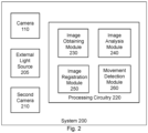
- FIG. 2 a block diagram schematically illustrating an example of a system 200 for detecting movement of at least one NLOS object 120 (hereinafter, "the NLOS object 120") within a space 130 outside the line-of-sight of the camera 110, in accordance with the presently disclosed subject matter.
- system 200 is configured to include a camera 110.
- Camera 110 is capable of acquiring a sequence of at least two successive images, as detailed further herein, inter alia with reference to Figs. 4 to 7 .
- system 200 can be configured to include an external non-natural light source 205 for illuminating the NLOS object 120, the external non-natural light source 205 being an ambient light source, as defined above.
- external non-natural light source 205 can be a Continuous Wave (CW) laser.
- CW Continuous Wave
- external non-natural light source 205 can be a flashlight, a different laser or another light projector.
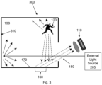
- Fig. 3 a schematic illustration of an exemplary arrangement of an external non-natural light source 205 with respect to the space 130, in accordance with the presently disclosed subject matter.
- the external non-natural light source 205 can illuminate a second inner wall 310 of the space 130 opposite the external non-natural light source 205.
- external non-natural light source 205 can illuminate or contribute to the illumination of the space 130 and, by extension, the NLOS object 120.
- the description of the collection of the scattered light 150 by camera 110, the scattered light 150 including secondary scatterings of light from the NLOS object 120, is described above in the description of Fig. 1 .
- the external non-natural light source 205 may be modulated with one or more predefined temporal characteristics.
- system 200 can also be configured to include a second camera 210, having a higher sampling rate than a sampling rate of the camera 110.
- Second camera 210 is capable of acquiring a second sequence of at least two second successive images, as detailed further herein, inter alia with reference to Fig. 3 .
- System 200 further comprises processing circuitry 220.
- Processing circuitry 220 can include one or more processing units (e.g. central processing units), microprocessors, microcontrollers (e.g. microcontroller units (MCUs)) or any other computing devices or modules, including multiple and/or parallel and/or distributed processing units, which are adapted to independently or cooperatively process data for controlling relevant system 200 resources and for enabling operations related to system 200 resources.
- processing units e.g. central processing units
- microprocessors e.g. microcontroller units (MCUs)
- MCUs microcontroller units
- Processing circuitry 220 can be configured to include the following modules: an image obtaining module 230, an image analysis module 240, optionally an image registration module 250, and a movement detection module 260.
- Processing circuitry 220 can be configured, e.g. using image obtaining module 230, to obtain the sequence of at least two successive images acquired by the camera 110, as detailed further herein, inter alia with reference to Figs. 4 , 5 and 7 . In some cases, processing circuitry 220 can also be configured, e.g. using image obtaining module 230, to obtain the second sequence of at least two second successive images acquired by the second camera 210, as detailed further herein, inter alia with reference to Fig. 4 .
- Processing circuitry 220 can also be configured, e.g. using image analysis module 240, to analyze at least two images of the sequence of the successive images acquired by the camera 110, as detailed further herein, inter alia with reference to Fig. 4 and 7 . Moreover, in some cases, processing circuitry 220 can be configured, e.g. using image analysis module 240, to analyze at least two second images of the second sequence of the second successive images acquired by the second camera 210, as detailed further herein, inter alia with reference to Fig. 4 .
- processing circuitry 220 can be configured, e.g. using image registration module 250, to register into a common coordinate system at least (a) a first image of the sequence of the images acquired by the camera 110, being a movable camera 110, giving rise to a first registered image, and (b) a second image of the sequence of the images acquired by the movable camera 110, giving rise to a second registered image, as detailed further herein, inter alia with reference to Fig. 7 .
- Processing circuitry 220 can be further configured, e.g. using movement detection module 260, to detect movement of the NLOS object 120 within a space 130 outside the line-of-sight of the camera 110, as detailed further herein, inter alia with reference to Figs. 4 , 6A , 6C and 7 .
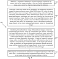
- FIG. 4 a flowchart illustrating an example of a first method 400 for detecting movement of the NLOS object 120 within a space 130 outside the line-of-sight (LOS) of the camera 110, in accordance with the presently disclosed subject matter.
- LOS line-of-sight
- a target and a reference are selected.
- the target is selected to be at least part of a first visible object that is: (a) located within a LOS of the camera 110, (b) impacted by light that is scattered from the NLOS object 120 present within the space 130 outside the LOS of the camera 110, and (c) impacted by ambient light (e.g., sunlight or light from a light projector or flashlight).
- ambient light e.g., sunlight or light from a light projector or flashlight.
- the reference is selected to be at least part of a second visible object that is: (a) located within a LOS of the camera 110, and (b) impacted by the ambient light that impacts the target. Accordingly, changes in ambient light conditions (direction, power, spectrum, polarization, etc.) of the ambient light that impacts the reference, i.e. reference ambient light conditions, results in changes in the light that impacts the reference. Moreover, movement of the NLOS object 120 within the space 130 outside the LOS of the camera 110 does not result in changes in the light that impacts the reference.
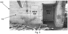
- the target can be first region-of-interest (ROI-I) 510, being part of an internal wall of the space 130 (e.g., a room) in which the NLOS object 120 (not shown in Fig. 5 ) is present, and the reference can be second region-of-interest (ROI-II) 520, being part of an external wall of the space 130.
- ROI-I region-of-interest
- the reference can be second region-of-interest
- the first visible object and the second visible object can be a common object, e.g. an internal wall of the space 130, such that the target can be a first part of the common object and the reference can be a second part of the common object that does not entirely overlap the first part of the common object.
- Implementation of the first method 400 requires that the interior of the space 130 be lighted, e.g. by at least one of internal light from at least one internal light source that is internal to the space 130 (e.g., a fluorescent light source), or ambient light, defined earlier herein, inter alia with reference to Fig. 1 .
- Some of the light that lights the interior of the space 130 impinges on the NLOS object 120 present within the space 130 outside the LOS of the camera 110.
- some of the light that impinges on the NLOS object 120 is scattered off of the NLOS object 120.
- At least some of the light that is scattered off of the NLOS object 120 directly or indirectly impacts the target (e.g., ROI-I 510), thereby enabling implementation of the first method 400.
- processing circuitry 220 can be configured, e.g. using image obtaining module 230, to obtain a sequence of at least two successive images acquired by the camera 110, each of the images including a first set of pixels representing the target (e.g., ROI-I 510), and a second set of pixels representing the reference (e.g., ROI-II 520) (block 404).
- image obtaining module 230 to obtain a sequence of at least two successive images acquired by the camera 110, each of the images including a first set of pixels representing the target (e.g., ROI-I 510), and a second set of pixels representing the reference (e.g., ROI-II 520) (block 404).
- processing circuitry 220 can be configured to automatically select the target (e.g., ROI-I 510) by analyzing at least one image of the sequence of images acquired by the camera 110 and obtained by processing circuitry 220. Additionally, or alternatively, in some cases, processing circuitry 220 can be configured to automatically select the reference (e.g., ROI-II 520) by analyzing at least one image of the sequence.
- target e.g., ROI-I 510
- processing circuitry 220 can be configured to automatically select the reference (e.g., ROI-II 520) by analyzing at least one image of the sequence.
- Processing circuitry 220 can be configured, e.g. using image analysis module 240, to analyze at least two images of the sequence of the at least two successive images acquired by the camera 110 for detecting the movement of the NLOS object 120 within the space 130, if any, by calculating, for each image of the at least two images of the sequence, (a) at least one target light intensity value based on at least part of the first set of pixels in the respective image, thereby giving rise to target light intensity values for the at least two images of the sequence, and (b) at least one reference light intensity value based on at least part of the second set of pixels in the respective image, thereby giving rise to reference light intensity values for the at least two images of the sequence (block 408).
- image analysis module 240 to analyze at least two images of the sequence of the at least two successive images acquired by the camera 110 for detecting the movement of the NLOS object 120 within the space 130, if any, by calculating, for each image of the at least two images of the sequence, (a) at least one target light intensity value based on
- the target light intensity values can vary across the at least two images of the sequence as a result of (i) the movement of the NLOS object 120 within the space 130 outside the LOS of the camera 110 over a first time period during which the images are acquired, and (ii) changes in the target ambient light conditions over the first time period.
- the reference light intensity values can vary across the at least two images of the sequence as a result of changes in the reference ambient light conditions over the first time period, and not as a result of the movement of the NLOS object 120 within the space 130 outside the LOS of the camera 110 over the first time period.
- the at least two images of the sequence can be successive images acquired by the camera 110, wherein an interval between each pair of images of the at least two images of the sequence is uniform or otherwise known by the processing circuitry 220.
- the at least two images of the sequence are not successive images acquired by the camera 110, wherein an interval between each pair of images of the at least two images of the sequence is known by the processing circuitry 220.
- a separation in time between the respective pair of images must be less than a given time interval to enable detecting movement of the NLOS object 120 within the space 130.
- the target light intensity value can be an average level of light intensity within the at least part of the first set of pixels in the respective image, referred to hereinafter as a target average level of light intensity for the respective image
- the reference light intensity value can be an average level of light intensity within the at least part of the second set of pixels in the respective image, referred to hereinafter as a reference average level of light intensity for the respective image.
- the target e.g., ROI-510
- the reference e.g., ROI-520
- Each target region of the target regions can include respective first pixels of the first set of pixels representing the target (e.g., ROI-510)
- each reference region of the reference regions can include respective second pixels of the second set of pixels representing the reference (e.g., ROI-520).
- a plurality of target light intensity values (e.g., target average levels of light intensity) can be calculated corresponding to the plurality of target regions, each target light intensity value of the target light intensity values being calculated based on at least part of the first pixels within a respective target region of the target regions.
- a plurality of reference light intensity values (e.g., reference average levels of light intensity) can be calculated corresponding to the plurality of reference regions, each reference light intensity value of the reference light intensity values being calculated based on at least part of the second pixels within a respective reference region of the reference regions.
- Fig. 6A is an exemplary target light intensity graph 600 that illustrates variations in a target average level of light intensity 610 across the sequence of images 620 acquired by the camera 110, in accordance with the presently disclosed subject matter.
- the variations in the target average level of light intensity 610 that are encompassed by first dotted ovals 625 result from (i) the movement of the NLOS object 120 within the space 130 outside the LOS of the camera 110 over a second time period during which given images of the sequence of images 620 are acquired by the camera 110, and (ii) changes in the target ambient light conditions over the second time period.
- the variations in the target average level of light intensity 610 that are not encompassed by the first dotted ovals 625 result from changes in the target ambient light conditions.
- Fig. 6B is an exemplary reference light intensity graph 630 that illustrates variations in a reference average level of light intensity 640 across the sequence of images 620, in accordance with the presently disclosed subject matter.
- the variations in the reference average level of light intensity 640 result from changes in the reference ambient light conditions over the first time period during which the sequence of images 620 is acquired by the camera 110.
- the target light intensity values can vary across the sequence of images (e.g., 620) based on second changes in the internal light of one or more given internal light sources within the space 130 across the sequence of images (e.g., 620).
- the changes in the internal light of a respective internal light source of the given internal light sources can result from a flickering of an alternating current (AC) power source that powers the respective internal light source.
- AC alternating current
- the changes in the internal light of a respective internal light source of the given internal light sources can result from light fluctuations that are intrinsic to the respective internal light source (e.g. light fluctuations from a ceiling fan that is coupled to the respective internal light source, etc.).
- processing circuitry 220 can be configured, e.g. using image obtaining module 230, to obtain a second sequence of at least two second successive images acquired by second camera 210 concurrently to obtaining a sequence of at least two successive images acquired by the camera 110, each of the second successive images acquired by second camera 210 including a third set of pixels representing the target (e.g., ROI-I 510).
- the sampling rate of the second camera 210 is higher than the sampling rate of the camera 110, such that the second camera 210 is characterized by a lower signal-to-noise ratio (SNR) than the camera 110.
- SNR signal-to-noise ratio
- Processing circuitry 220 can also be configured, e.g. using image analysis module 240, to analyze at least two second images of the second sequence, by calculating, for each second image of the at least two second images of the second sequence, at least one second target light intensity value based on at least part of the third set of pixels in the respective second image, thereby giving rise to second target light intensity values for the at least two second images of the second sequence. Since the second camera 210 is characterized by a lower SNR than the camera 110, the second camera 210 is not capable of detecting the subtle differences in the light within the target (e.g., ROI-I 510) due to the motion of the NLOS object 120.
- the target e.g., ROI-I 510
- the second target light intensity values can vary across the at least two second images of the second sequence as a result of the second changes in the internal light of the given internal light sources within the space 130 and the changes in the target ambient light conditions over a third time period during which the at least two second images of the second sequence are acquired, and not as a result of the movement of the NLOS object 120 within the space 130 outside the LOS of the camera 110 over the third time period.
- the third time period can be the first time period.
- processing circuitry 220 can be configured, e.g.
- image analysis module 240 uses image analysis module 240, to correct the target light intensity values calculated for the at least two images of the sequence acquired by the camera 110, based on the second target light intensity values calculated for the at least two second images of the second sequence acquired by the second camera 210, to at least reduce a second effect of the second changes in the internal light of the given internal light sources on the target light intensity values.
- processing circuitry 220 can be configured, e.g. using image analysis module 240, to calculate, for each image of the at least two images of the sequence, at least one compensated light intensity value.
- the compensated light intensity value for a respective image can be the target light intensity value for the respective image, optionally corrected to at least reduce the second effect, on the target light intensity value, of the second changes in the internal light between a given image (e.g., initial image) of the sequence of images (e.g., 620) acquired by the camera 110 and the respective image, and as modified, based on the reference light intensity value for the respective image, to reduce an effect, on the target light intensity value, of changes in the target ambient light conditions between the given image and the respective image.
- the compensated light intensity value for each image can be calculated based on a mathematical operation that includes a relation between the target light intensity value for the respective image and the reference light intensity value for the respective image.
- the compensated light intensity value for a respective image can be calculated by dividing the target light intensity value for the respective image by the reference light intensity value for the respective image.
- the target light intensity value for the respective image that is used for the calculation of the compensated light intensity value for the respective image can be the target light intensity value based on the at least part of the first set of pixels in the respective image, corrected to at least reduce a second effect of the second changes in the internal light of given internal light sources.
- the compensated light intensity values for the at least two images of the sequence can represent a compensated average level of light intensity for the at least two images of the sequence, as illustrated in Fig. 6C .
- FIG. 6C an exemplary compensated light intensity graph 650 that illustrates variations in a compensated average level of light intensity 660 across the sequence of images 620, in accordance with the presently disclosed subject matter.
- creation of the graph 650 assumes that a target average level of light intensity 610 and a reference average level of light intensity 640 is calculated for each image in the sequence of images 620 acquired by the camera 110, such that a compensated average level of light intensity 660 is calculated for each image in the sequence of images 620 with the exception of the first image in the sequence of images 620.
- the variations in the compensated average level of light intensity 660 that are encompassed by second dotted ovals 665 result from the movement of the NLOS object 120 within the space 130 outside the LOS of the camera 110 over the second time period, defined above.
- the target light intensity value for the respective image can be represented by a temporal target equation and the reference light intensity value for the respective image can be represented by a temporal reference equation.
- system 200 can be configured to infer a common signal represented in both (a) the temporal reference equation and (b) a part of the temporal target equation that represents a temporal change in the target light intensity value due to the ambient light that pervades into the space 130 and illuminates the target (e.g., ROI-I 510) in order to reduce a variance of the compensated light intensity values.
- the representation of the common signal can appear in both (a) the temporal reference equation and (b) the part of the temporal target equation in explicit form or in a more complex form.
- the inferring of the common signal can be achieved, for example, using machine learning (e.g., deep learning) techniques.
- Equation 1 assumes that the space 130 is not illuminated by internal light from an internal light source that is internal to the space 130.
- L D (t) can be zero.
- the coefficients R W1 and R W2 can be different.
- the coefficients R W1 and R W2 can be different (but are not necessarily different).
- the coefficients Rwi and R W2 can be the same.
- the coefficients R W1 and R W2 can be the same.
- processing circuitry 220 can be configured, prior to performing the first method 400 and based on acquired images of the target (e.g., ROI-510) and the reference (e.g., ROI-II 520), to determine the coefficients, i.e. the multiplicative factors, for the temporal target equation and the temporal reference equation (e.g., coefficients R W1 and R H (t) of Equation 1 and coefficient R W2 of Equation 2).
- Processing circuitry 220 can be configured, e.g. using movement detection module 260, to detect the movement of the NLOS object 120 within the space 130 by detecting a variation between the compensated light intensity values across the at least two images of the sequence, wherein the variation meets a criterion (block 416).
- the criterion can be a predefined absolute or relative value of a difference in magnitude between the compensated light intensity values across the at least two images of the sequence that is met or exceeded. Additionally, or alternatively, in some cases, the criterion can be a predefined temporal variation between the compensated light intensity values across the at least two images of the sequence that is met or exceeded, the predefined temporal variation being for example a predefined change in a temporal spectrum (i.e., harmonics) content, a wavelet content, or both.
- a temporal spectrum i.e., harmonics
- FIG. 7 a flowchart illustrating an example of a second method 700 for detecting movement of at least one non-line-of-sight (NLOS) object 120 within a space 130 outside the line-of-sight (LOS) of the camera 110, being a movable camera 110, during movement of the camera 110, in accordance with the presently disclosed subject matter.
- NLOS non-line-of-sight
- LOS line-of-sight
- each of the images that are acquired by the movable camera 110 can include a first set of pixels representing a target (e.g., ROI-I 510), the target (e.g., ROI-I 510) being at least part of a first visible object located within a line-of-sight of the camera 110, the first visible object being impacted by (i) light that is scattered from the non-line-of-sight object present within a space 130 outside the line-of-sight of the camera 110 and (ii) ambient light.
- a target e.g., ROI-I 510
- the target e.g., ROI-I 510
- the first visible object being impacted by (i) light that is scattered from the non-line-of-sight object present within a space 130 outside the line-of-sight of the camera 110 and (ii) ambient light.
- each of the images can include a second set of pixels representing a reference (e.g., ROI-II 520), the reference (e.g., ROI-II 520) being at least part of a second visible object located within the line-of-sight of the camera 110, the second visible object being impacted by the ambient light.
- the target e.g., ROI-I 510
- the reference e.g., ROI-II 520
- the target e.g., ROI-I 510
- the reference e.g., ROI-II 520
- each of the images that are acquired by the movable camera 110 for the implementation of the second method 700 can include a respective set of pixels that represent a target (e.g., 160), the target (e.g., ROI-I 510) being at least part of a first visible object located within a line-of-sight of the camera 110, the first visible object being impacted by light that is scattered from the non-line-of-sight object within a space 130 outside the line-of-sight of the camera 110.
- the target can be selected as described in Fig. 4 . Attention is drawn to Figs.
- FIG. 1 and 3 which illustrate an environment in which the second method 700 can be implemented based on images that capture only the target, the target being, for example, a part 160 of the inner wall 170 of the space 130.
- the part 160 of the inner wall 170 of the space 130 can vary over time.
- Implementation of the second method 700 requires that the interior of the space 130 be lighted, e.g. by at least one of internal light from at least one internal light source that is internal to the space 130 (e.g., a fluorescent light source), or ambient light, defined earlier herein, inter alia with reference to Fig. 1 .
- at least some of the ambient light can be emitted by an external non-natural light source 205, as detailed earlier herein, inter alia with reference to Fig. 3 .
- Some of the light that illuminates the interior of the space 130 impinges on the NLOS object 120 present within the space 130 outside the LOS of the movable camera 110.
- some of the light that impinges on the NLOS object 120 is scattered off of the NLOS object 120.
- At least some of the light that is scattered off of the NLOS object 120 directly or indirectly impacts the target (e.g., 160, 510), thereby enabling implementation of the second method 700.
- the movable camera 110 can be mounted on one of an aircraft, a ground vehicle, a nautical vehicle, a fixed surface, or a person. Additionally, or alternatively, in some cases, the movable camera 110 can be gimbaled.
- processing circuitry 220 can be configured, e.g. using image obtaining module 230, to obtain a sequence of at least two successive images (e.g., 620) acquired by the movable camera 110.
- Each of the images include a respective set of pixels, wherein at least a subset of the respective set of pixels represent a target (e.g., 160, 510) (block 704).
- the respective set of pixels in the images can include a first set of pixels representing a target (e.g., ROI-I 510), and a second set of pixels representing a reference (e.g., ROI-II 520).
- the first visible object including the target and the second visible object including the reference can be different parts of a common object.
- processing circuitry 220 can be configured, e.g.
- image registration module 250 to register into a common coordinate system at least: (a) the respective set of pixels of a first image of the sequence of images (e.g., 620), giving rise to a first registered image, and (b) the respective set of pixels of a second image of the sequence (e.g., 620), giving rise to a second registered image, wherein the first image is acquired from a first position of the movable camera 110 and the second image is acquired from a second position of the movable camera 110, different than the first position, and wherein the registration enables identifying the target within the first registered image and within the second registered image (block 708).
- the respective set of pixels includes a first set of pixels representing the target and a second set of pixels representing the reference
- the registration can enable identifying both the target and the reference within the first registered image and within the second registered image.
- At least one inertial sensor can be affixed to the movable camera 110. Registration into the common coordinate system can also be based on readings from the inertial sensor.
- processing circuitry 220 can be configured to maintain a line-of-sight of the movable camera 110 to the first visible object including the target (e.g., 160, 510). Moreover, in some cases, in which the respective set of pixels includes a second set of pixels representing a reference, processing circuitry 220 can also be configured to maintain a line-of-sight of the movable camera 110 to the second visible object including the reference (e.g., 520).
- Processing circuitry 220 can be configured, e.g. using image analysis module 240, to calculate at least one target light intensity value for the first registered image and the second registered image based on at least part of the respective set of pixels representing the target (e.g., 160, 510) in the respective registered image, thereby giving rise to target light intensity values for the first registered image and the second registered image (block 712).
- image analysis module 240 to calculate at least one target light intensity value for the first registered image and the second registered image based on at least part of the respective set of pixels representing the target (e.g., 160, 510) in the respective registered image, thereby giving rise to target light intensity values for the first registered image and the second registered image (block 712).
- the target light intensity value for the first registered image and the second registered image can be a target average level of light intensity (e.g., 610) for the respective registered image.
- the target e.g., 160, 510
- the target can be divided into a plurality of non-overlapping target regions that together complete the target (e.g., 160, 510), as detailed earlier herein, inter alia with reference to Fig. 4 .
- a plurality of target light intensity values (e.g., target average levels of light intensity) can be calculated corresponding to the plurality of target regions, each target light intensity value of the target light intensity values being calculated based on at least part of the respective pixels within a respective target region of the target regions.
- the target light intensity values can each be represented by a temporal target equation, as detailed earlier herein, inter alia with reference to Fig. 4 .
- the coefficients in the temporal target equation can be determined prior to performing the second method 700, as detailed earlier herein, inter alia with reference to Fig. 4 .
- the target light intensity values in the first registered image and the second registered image can be corrected to at least reduce a second effect of second changes in the internal light of given internal light sources within the space 130 on the target light intensity values, as detailed earlier herein, inter alia with reference to Fig. 4 .
- processing circuitry 220 can be configured to compensate for the effect of differences in sensitivity of different pixels and their offsets on the values of light intensity of the different pixels in the first registered image and the second registered image that are associated with a same area of an object (e.g., the target or the reference).
- processing circuitry 220 can be configured, e.g. using movement detection module 260, to detect the movement of the NLOS object 120 within the space 130 upon a variation in a target light intensity value between the first registered image and the second registered image meeting a criterion (block 716).
- the criterion can be a predefined absolute or relative value of a difference in magnitude between the target light intensity values of the first registered image and the second registered image that is met or exceeded. Additionally, or alternatively, in some cases, the criterion can be a predefined temporal variation between the target light intensity values of the first registered image and the second registered image that is met or exceeded, the predefined variation being for example a predefined change in a temporal spectrum (i.e., harmonics) content, a wavelet content, or both.
- a temporal spectrum i.e., harmonics
- processing circuitry 220 can be configured, e.g. using movement detection module 260, to detect the movement of the NLOS object 120 within the space 130 upon a variation in a compensated light intensity value (e.g., compensated average value of light intensity) between the first registered image and the second registered image meeting a criterion, the compensated light intensity values being calculated based on corresponding target light intensity values and reference light intensity values, as detailed earlier herein, inter alia with reference to Fig. 4 .
- a compensated light intensity value e.g., compensated average value of light intensity
- the reference light intensity values can each be represented by a temporal reference equation, as detailed earlier herein, inter alia with reference to Fig. 4 .
- the coefficients in the temporal reference equation can be determined prior to performing the second method 700, as detailed earlier herein, inter alia with reference to Fig. 4 .
- the criterion can be a predefined absolute or relative value of a difference in magnitude between the compensated light intensity values of the first registered image and the second registered image that is met or exceeded. Additionally, or alternatively, in some cases, the criterion can be a predefined temporal variation between the compensated light intensity values of the first registered image and the second registered image that is met or exceeded, the predefined temporal variation being for example a predefined change in a temporal spectrum (i.e., harmonics) content, a wavelet content, or both.
- a temporal spectrum i.e., harmonics
- system can be implemented, at least partly, as a suitably programmed computer.
- the presently disclosed subject matter contemplates a computer program being readable by a computer for executing the disclosed method.
- the presently disclosed subject matter further contemplates a machine-readable memory tangibly embodying a program of instructions executable by the machine for executing the disclosed method.
Landscapes
- Engineering & Computer Science (AREA)
- Physics & Mathematics (AREA)
- General Physics & Mathematics (AREA)
- Electromagnetism (AREA)
- Theoretical Computer Science (AREA)
- Multimedia (AREA)
- Computer Networks & Wireless Communication (AREA)
- Radar, Positioning & Navigation (AREA)
- Remote Sensing (AREA)
- Computer Vision & Pattern Recognition (AREA)
- Image Processing (AREA)
- Image Analysis (AREA)
- Length Measuring Devices By Optical Means (AREA)
- Eye Examination Apparatus (AREA)
Claims (15)
- System (200) zum Erkennen der Bewegung mindestens eines Nicht-Sichtlinien-Objekts (120) in einem Raum (130), wobei das System (200) Folgendes umfasst:eine Kamera (110), die in der Lage ist, Bilder zu erfassen von:(A) mindestens einem Teil eines ersten sichtbaren Objekts, das sich in einer Sichtlinie der Kamera (110) befindet und ein Ziel darstellt, wobei das erste sichtbare Objekt von (i) Licht, das von dem Nicht-Sichtlinien-Objekt (120) gestreut wird, das in dem Raum (130) außerhalb der Sichtlinie der Kamera (110) vorhanden ist, und (ii) von Umgebungslicht getroffen wird, und(B) mindestens einem Teil eines zweiten sichtbaren Objekts, das sich in der Sichtlinie der Kamera (110) befindet und eine Referenz darstellt, wobei das zweite sichtbare Objekt von dem Umgebungslicht getroffen wird; undeine Verarbeitungsschaltung (220), die dazu ausgebildet ist:eine Sequenz von mindestens zwei aufeinanderfolgenden Bildern zu erhalten, die von der Kamera (110) erfasst wurden, wobei jedes der aufeinanderfolgenden Bilder einen ersten Satz von Pixeln enthält, die das Ziel darstellen, und einen zweiten Satz von Pixeln, die die Referenz darstellen;mindestens zwei Bilder der Sequenz zu analysieren, um die Bewegung des mindestens einen Nicht-Sichtlinien-Objekts (120) in dem Raum (130), falls vorhanden, zu erkennen, indem für jedes Bild der mindestens zwei Bilder der Sequenz Folgendes berechnet wird:(a) mindestens ein Zielwert der Lichtintensität auf der Basis mindestens eines Teils des ersten Satzes von Pixeln in dem jeweiligen Bild, wodurch man Zielwerte der Lichtintensität für die mindestens zwei Bilder der Sequenz erhält,(b) mindestens ein Referenzwert der Lichtintensität auf der Basis mindestens eines Teils des zweiten Satzes von Pixeln in dem jeweiligen Bild, wodurch man Referenzwerte der Lichtintensität für die mindestens zwei Bilder der Sequenz erhält, und(c) mindestens ein kompensierter Wert der Lichtintensität, wobei der kompensierte Wert der Lichtintensität berechnet wird durch Modifizieren des Zielwerts der Lichtintensität auf der Basis des Referenzwerts der Lichtintensität, um einen an dem Zielwert der Lichtintensität auftretenden Effekt der Änderungen im Umgebungslicht zwischen einem ersten Zeitpunkt, an dem ein gegebenes Bild der Sequenz erfasst wird, und einem zweiten Zeitpunkt, an dem das jeweilige Bild erfasst wird, zu reduzieren, wodurch man kompensierte Werte der Lichtintensität für die mindestens zwei Bilder der Sequenz erhält; unddie Bewegung des mindestens einen Nicht-Sichtlinien-Objekts (120) in dem Raum (130) zu erkennen, indem eine Veränderung zwischen den kompensierten Werten der Lichtintensität über die mindestens zwei Bilder der Sequenz erfasst wird, wobei die Veränderung ein Kriterium erfüllt.
- System (200) nach Anspruch 1, wobei: (a) der Zielwert der Lichtintensität durch eine zeitliche Zielgleichung repräsentiert wird und (b) der Referenzwert der Lichtintensität durch eine zeitliche Referenzgleichung repräsentiert wird, und
wobei die Verarbeitungsschaltung (220) ferner dazu ausgebildet ist:
ein gemeinsames Signal herzuleiten, das sowohl in der zeitlichen Referenzgleichung als auch in einem Teil der zeitlichen Zielgleichung repräsentiert wird und eine zeitliche Änderung im Zielwert der Lichtintensität repräsentiert, weil das Umgebungslicht in den Raum (130) dringt und das Ziel beleuchtet, um eine Varianz der kompensierten Werte der Lichtintensität zu verringern. - System (200) nach Anspruch 1, wobei der kompensierte Wert der Lichtintensität berechnet wird, indem der Zielwert der Lichtintensität durch den Referenzwert der Lichtintensität dividiert wird.
- System (200) nach Anspruch 1, wobei das zweite sichtbare Objekt nicht von dem Licht getroffen wird, das von dem Nicht-Sichtlinien-Objekt (120) gestreut wird, das in dem Raum (130) außerhalb der Sichtlinie der Kamera (110) vorhanden ist.
- System (200) nach Anspruch 1, wobei wenigstes etwas von dem Umgebungslicht durch eine externe Quelle (205) von nicht-natürlichem Licht abgestrahlt wird, um das Nicht-Sichtlinien-Objekt (120) zu beleuchten.
- System (200) nach Anspruch 1, wobei das Kriterium eine vordefinierte zeitliche Veränderung zwischen den kompensierten Werten der Lichtintensität über die mindestens zwei Bilder der Sequenz ist, die erfüllt oder übertroffen wird.
- System (200) nach Anspruch 1, wobei das Innere des Raums (130) durch ein inneres Licht von mindestens einer inneren Lichtquelle beleuchtet wird, die sich im Inneren des Raums (130) befindet;wobei das System (200) ferner eine zweite Kamera (210) mit einer höheren Abtastrate als eine Abtastrate der Kamera (110) umfasst, undwobei die Verarbeitungsschaltung (220) ferner dazu ausgebildet ist:eine zweite Sequenz von mindestens zwei zweiten aufeinanderfolgenden Bildern zu erhalten, die von der zweiten Kamera (210) erfasst wurden, wobei jedes der zweiten aufeinanderfolgenden Bilder einen dritten Satz von Pixeln enthält, der das Ziel repräsentiert;mindestens zwei zweite Bilder der zweiten Sequenz zu analysieren, indem für jedes zweite Bild der mindestens zwei zweiten Bilder der zweiten Sequenz mindestens ein zweiter Zielwert der Lichtintensität auf der Basis mindestens eines Teils des dritten Satzes von Pixeln in dem jeweiligen zweiten Bild berechnet wird, wodurch man zweite Zielwerte der Lichtintensität für die mindestens zwei zweiten Bilder der zweiten Sequenz erhält, wobei die zweiten Zielwerte der Lichtintensität über die mindestens zwei zweiten Bilder der zweiten Sequenz infolge von zweiten Änderungen in dem inneren Licht von der mindestens einen inneren Lichtquelle, die sich im Inneren des Raums (130) befindet, variieren, und nicht infolge der Bewegung des Nicht-Sichtlinien-Objekts (120) in dem Raum (130); unddie Zielwerte der Lichtintensität auf der Basis der zweiten Zielwerte der Lichtintensität so zu korrigieren, dass mindestens ein zweiter Effekt der zweiten Änderungen in dem inneren Licht von der mindestens einen inneren Lichtquelle, die sich im Inneren des Raums (130) befindet, auf die Zielwerte der Lichtintensität verringert wird.
- Verfahren (400) zum Erkennen der Bewegung mindestens eines Nicht-Sichtlinien-Objekts (120) in einem Raum (130), wobei das Verfahren (400) die folgenden Schritte umfasst:Erhalten (404) einer Sequenz von mindestens zwei aufeinanderfolgenden Bildern, die von einer Kamera (110) erfasst wurden, wobei jedes der aufeinanderfolgenden Bilder Folgendes enthält: einen ersten Satz von Pixeln, die ein Ziel repräsentieren, wobei das Ziel wenigstens ein Teil eines ersten sichtbaren Objekts ist, das sich in einer Sichtlinie der Kamera (110) befindet, und einen zweiten Satz von Pixeln, die eine Referenz repräsentieren, wobei die Referenz wenigstens ein Teil eines zweiten sichtbaren Objekts ist, das sich in der Sichtlinie der Kamera (110) befindet, wobei das erste sichtbare Objekt von (i) Licht getroffen wird, das von dem Nicht-Sichtlinien-Objekt (120) gestreut wird, das in dem Raum (130) außerhalb der Sichtlinie der Kamera (110) vorhanden ist, und (ii) von Umgebungslicht getroffen wird, und wobei das zweite sichtbare Objekt von dem Umgebungslicht getroffen wird;Analysieren (408, 412) von mindestens zwei Bildern der Sequenz, um die Bewegung des mindestens einen Nicht-Sichtlinien-Objekts (120) in dem Raum (130), falls vorhanden, zu erkennen, indem für jedes Bild der mindestens zwei Bilder der Sequenz Folgendes berechnet wird:(a) mindestens ein Zielwert der Lichtintensität auf der Basis mindestens eines Teils des ersten Satzes von Pixeln in dem jeweiligen Bild, wodurch man Zielwerte der Lichtintensität für die mindestens zwei Bilder der Sequenz erhält,(b) mindestens ein Referenzwert der Lichtintensität auf der Basis wenigstens eines Teils des zweiten Satzes von Pixeln in dem jeweiligen Bild, wodurch man Referenzwerte der Lichtintensität für die mindestens zwei Bilder der Sequenz erhält, und(c) mindestens ein kompensierter Wert der Lichtintensität, wobei der kompensierte Wert der Lichtintensität berechnet wird durch Modifizieren des Zielwerts der Lichtintensität auf der Basis des Referenzwerts der Lichtintensität, um einen an dem Zielwert der Lichtintensität auftretenden Effekt von Änderungen im Umgebungslicht zwischen einem ersten Zeitpunkt, an dem ein gegebenes Bild der Sequenz erfasst wird, und einem zweiten Zeitpunkt, an dem das jeweilige Bild erfasst wird, zu verringern, wodurch man kompensierte Werte der Lichtintensität für die mindestens zwei Bilder der Sequenz erhält;undErkennen (416) der Bewegung des mindestens einen Nicht-Sichtlinien-Objekts (120) in dem Raum (130) durch Erfassen einer Veränderung zwischen den kompensierten Werten der Lichtintensität über die mindestens zwei Bilder der Sequenz, wobei die Veränderung ein Kriterium erfüllt.
- Verfahren (400) nach Anspruch 8, wobei: (a) der Zielwert der Lichtintensität durch eine zeitliche Zielgleichung repräsentiert wird und (b) der Referenzwert der Lichtintensität durch eine zeitliche Referenzgleichung repräsentiert wird, und
wobei das Verfahren (400) ferner folgenden Schritt umfasst:
Herleiten eines gemeinsamen Signals, das sowohl in der zeitlichen Referenzgleichung als auch in einem Teil der zeitlichen Zielgleichung repräsentiert wird und eine zeitliche Veränderung in dem Zielwert der Lichtintensität repräsentiert, weil das Umgebungslicht in den Raum (130) dringt und das Ziel beleuchtet, um eine Varianz der kompensierten Werte der Lichtintensität zu verringern. - Verfahren (400) nach Anspruch 8, wobei der kompensierte Wert der Lichtintensität berechnet wird, indem der Zielwert der Lichtintensität durch den Referenzwert der Lichtintensität dividiert wird.
- Verfahren (400) nach Anspruch 8, wobei das zweite sichtbare Objekt nicht von dem Licht getroffen wird, das von dem Nicht-Sichtlinien-Objekt (120) gestreut wird, das in dem Raum (130) außerhalb der Sichtlinie der Kamera (110) vorhanden ist.
- Verfahren (400) nach Anspruch 8, wobei wenigstes etwas von dem Umgebungslicht durch eine externe Quelle (205) von nicht-natürlichem Licht abgestrahlt wird, um das Nicht-Sichtlinien-Objekt (120) zu beleuchten.
- Verfahren (400) nach Anspruch 8, wobei das Kriterium eine vordefinierte zeitliche Veränderung zwischen den kompensierten Werten der Lichtintensität über die mindestens zwei Bilder der Sequenz ist, die erfüllt oder übertroffen wird.
- Verfahren (400) nach Anspruch 8, wobei das Innere des Raums (130) durch ein inneres Licht von mindestens einer inneren Lichtquelle beleuchtet wird, die sich im Inneren des Raums (130) befindet, und wobei das Verfahren (400) ferner die folgenden Schritte umfasst:Erhalten einer zweiten Sequenz von mindestens zwei zweiten aufeinanderfolgenden Bildern, die von einer zweiten Kamera (210) erfasst wurden, wobei die zweite Kamera (210) eine höhere Abtastrate besitzt als eine Abtastrate der Kamera (110), wobei jedes der zweiten aufeinanderfolgenden Bilder einen dritten Satz von Pixeln enthält, der das Ziel repräsentiert;Analysieren von mindestens zwei zweiten Bildern der zweiten Sequenz, indem für jedes zweite Bild der mindestens zwei zweiten Bilder der zweiten Sequenz mindestens ein zweiter Zielwert der Lichtintensität auf der Basis von wenigstens einem Teil des dritten Satzes von Pixeln in dem jeweiligen zweiten Bild berechnet wird, wodurch man zweite Zielwerte der Lichtintensität für die mindestens zwei zweiten Bilder der zweiten Sequenz erhält, wobei die zweiten Zielwerte der Lichtintensität über die mindestens zwei zweiten Bilder der zweiten Sequenz infolge von zweiten Änderungen im inneren Licht von der mindestens einen inneren Lichtquelle, die sich im Inneren des Raums (130) befindet, und nicht infolge der Bewegung des Nicht-Sichtlinien-Objekts (120) in dem Raum (130) variieren; undKorrigieren der Zielwerte der Lichtintensität auf der Basis der zweiten Zielwerte der Lichtintensität, um wenigstens einen zweiten Effekt der zweiten Änderungen in dem inneren Licht von der mindestens einen inneren Lichtquelle, die sich im Inneren des Raums (130) befindet, auf die Zielwerte der Lichtintensität zu verringern.
- Nichtflüchtiges computerlesbares Speichermedium mit einem damit verkörperten computerlesbaren Programmcode, wobei der computerlesbare Programmcode durch mindestens einen Prozessor eines Computers ausführbar ist, um ein Verfahren (400) zum Erkennen der Bewegung mindestens eines Nicht-Sichtlinien-Objekts (120) in einem Raum (130) durchzuführen, wobei das Verfahren die folgenden Schritte umfasst:Erhalten (404) einer Sequenz von mindestens zwei aufeinanderfolgenden Bildern, die von einer Kamera (110) erfasst wurden, wobei jedes der aufeinanderfolgenden Bilder Folgendes enthält: einen ersten Satz von Pixeln, die ein Ziel repräsentieren, wobei das Ziel wenigstens ein Teil eines ersten sichtbaren Objekts ist, das sich in einer Sichtlinie der Kamera (110) befindet, und einen zweiten Satz von Pixeln, die eine Referenz repräsentieren, wobei die Referenz wenigstens ein Teil eines zweiten sichtbaren Objekts ist, das sich in der Sichtlinie der Kamera (110) befindet, wobei das erste sichtbare Objekt von (i) Licht getroffen wird, das von dem Nicht-Sichtlinien-Objekt (120) gestreut wird, das in dem Raum (130) außerhalb der Sichtlinie der Kamera (110) vorhanden ist, und (ii) von Umgebungslicht getroffen wird, und wobei das zweite sichtbare Objekt von dem Umgebungslicht getroffen wird;Analysieren (408, 412) von mindestens zwei Bildern der Sequenz, um die Bewegung des mindestens einen Nicht-Sichtlinien-Objekts (120) in dem Raum (130), falls vorhanden, zu erkennen, indem für jedes Bild der mindestens zwei Bilder der Sequenz Folgendes berechnet wird:(a) mindestens ein Zielwert der Lichtintensität auf der Basis mindestens eines Teils des ersten Satzes von Pixeln in dem jeweiligen Bild, wodurch man Zielwerte der Lichtintensität für die mindestens zwei Bilder der Sequenz erhält,(b) mindestens ein Referenzwert der Lichtintensität auf der Basis wenigstens eines Teils des zweiten Satzes von Pixeln in dem jeweiligen Bild, wodurch man Referenzwerte der Lichtintensität für die mindestens zwei Bilder der Sequenz erhält, und(c) mindestens ein kompensierter Wert der Lichtintensität, wobei der kompensierte Wert der Lichtintensität berechnet wird durch Modifizieren des Zielwerts der Lichtintensität auf der Basis des Referenzwerts der Lichtintensität, um einen an dem Zielwert der Lichtintensität auftretenden Effekt von Änderungen im Umgebungslicht zwischen einem ersten Zeitpunkt, an dem ein gegebenes Bild der Sequenz erfasst wird, und einem zweiten Zeitpunkt, an dem das jeweilige Bild erfasst wird, zu verringern, wodurch man kompensierte Werte der Lichtintensität für die mindestens zwei Bilder der Sequenz erhält;undErkennen (416) der Bewegung des mindestens einen Nicht-Sichtlinien-Objekts (120) in dem Raum (130) durch Erfassen einer Veränderung zwischen den kompensierten Werten der Lichtintensität über die mindestens zwei Bilder der Sequenz, wobei die Veränderung ein Kriterium erfüllt.
Priority Applications (1)
| Application Number | Priority Date | Filing Date | Title |
|---|---|---|---|
| EP23163280.3A EP4220579A1 (de) | 2020-08-30 | 2021-06-08 | Systeme und verfahren zur erkennung der bewegung von mindestens einem nicht-sichtlinien-objekt |
Applications Claiming Priority (2)
| Application Number | Priority Date | Filing Date | Title |
|---|---|---|---|
| IL277062A IL277062B (en) | 2020-08-30 | 2020-08-30 | Systems and methods for detecting movement of at least one object without line of sight |
| PCT/IL2021/050683 WO2022043983A1 (en) | 2020-08-30 | 2021-06-08 | Systems and methods for detecting movement of at least one non-line-of-sight object |
Related Child Applications (2)
| Application Number | Title | Priority Date | Filing Date |
|---|---|---|---|
| EP23163280.3A Division-Into EP4220579A1 (de) | 2020-08-30 | 2021-06-08 | Systeme und verfahren zur erkennung der bewegung von mindestens einem nicht-sichtlinien-objekt |
| EP23163280.3A Division EP4220579A1 (de) | 2020-08-30 | 2021-06-08 | Systeme und verfahren zur erkennung der bewegung von mindestens einem nicht-sichtlinien-objekt |
Publications (4)
| Publication Number | Publication Date |
|---|---|
| EP4200817A1 EP4200817A1 (de) | 2023-06-28 |
| EP4200817A4 EP4200817A4 (de) | 2023-07-26 |
| EP4200817B1 true EP4200817B1 (de) | 2025-02-05 |
| EP4200817C0 EP4200817C0 (de) | 2025-02-05 |
Family
ID=80354794
Family Applications (2)
| Application Number | Title | Priority Date | Filing Date |
|---|---|---|---|
| EP21860735.6A Active EP4200817B1 (de) | 2020-08-30 | 2021-06-08 | Systeme und verfahren zur erkennung der bewegung von mindestens einem nicht-sichtlinien-objekt |
| EP23163280.3A Withdrawn EP4220579A1 (de) | 2020-08-30 | 2021-06-08 | Systeme und verfahren zur erkennung der bewegung von mindestens einem nicht-sichtlinien-objekt |
Family Applications After (1)
| Application Number | Title | Priority Date | Filing Date |
|---|---|---|---|
| EP23163280.3A Withdrawn EP4220579A1 (de) | 2020-08-30 | 2021-06-08 | Systeme und verfahren zur erkennung der bewegung von mindestens einem nicht-sichtlinien-objekt |
Country Status (4)
| Country | Link |
|---|---|
| US (2) | US11734833B2 (de) |
| EP (2) | EP4200817B1 (de) |
| IL (1) | IL277062B (de) |
| WO (1) | WO2022043983A1 (de) |
Families Citing this family (2)
| Publication number | Priority date | Publication date | Assignee | Title |
|---|---|---|---|---|
| WO2023224251A1 (en) * | 2022-05-16 | 2023-11-23 | Samsung Electronics Co., Ltd. | Systems and methods for recognizing non-line-of-sight human actions |
| DE102024101933A1 (de) * | 2024-01-24 | 2025-07-24 | Audi Aktiengesellschaft | Verfahren zum Betreiben einer Fahrerassistenzeinrichtung für ein Kraftfahrzeug, Fahrerassistenzeinrichtung für ein Kraftfahrzeug sowie Computerprogrammprodukt |
Family Cites Families (9)
| Publication number | Priority date | Publication date | Assignee | Title |
|---|---|---|---|---|
| US8373107B2 (en) | 2003-08-06 | 2013-02-12 | The United States Of America As Represented By The Secretary Of The Army | Method and apparatus for non-line-of-sight imaging of a first area using photons detected from a second area |
| US8446468B1 (en) * | 2007-06-19 | 2013-05-21 | University Of Southern California | Moving object detection using a mobile infrared camera |
| CN107408298B (zh) * | 2015-03-13 | 2021-05-28 | 日本电气株式会社 | 生命体检测设备、生命体检测方法和记录介质 |
| JP6767072B2 (ja) * | 2015-10-06 | 2020-10-14 | アズビル株式会社 | 距離設定型光電センサ |
| CN106878668B (zh) * | 2015-12-10 | 2020-07-17 | 微软技术许可有限责任公司 | 对物体的移动检测 |
| US10395539B2 (en) | 2016-03-31 | 2019-08-27 | GM Global Technology Operations LLC | Non-line of sight obstacle detection and localization |
| US10152798B2 (en) | 2017-04-10 | 2018-12-11 | Wisconsin Alumni Research Foundation | Systems, methods and, media for determining object motion in three dimensions using speckle images |
| US10317515B2 (en) | 2017-09-01 | 2019-06-11 | Wisconsin Alumni Research Foundation | Apparatus for identifying objects outside of a line-of-sight |
| US11436839B2 (en) * | 2018-11-02 | 2022-09-06 | Toyota Research Institute, Inc. | Systems and methods of detecting moving obstacles |
-
2020
- 2020-08-30 IL IL277062A patent/IL277062B/en unknown
-
2021
- 2021-06-08 EP EP21860735.6A patent/EP4200817B1/de active Active
- 2021-06-08 WO PCT/IL2021/050683 patent/WO2022043983A1/en not_active Ceased
- 2021-06-08 EP EP23163280.3A patent/EP4220579A1/de not_active Withdrawn
-
2023
- 2023-02-27 US US18/174,664 patent/US11734833B2/en active Active
- 2023-02-27 US US18/174,667 patent/US11734834B2/en active Active
Also Published As
| Publication number | Publication date |
|---|---|
| EP4200817A1 (de) | 2023-06-28 |
| US11734833B2 (en) | 2023-08-22 |
| EP4200817A4 (de) | 2023-07-26 |
| IL277062B (en) | 2022-02-01 |
| US20230237674A1 (en) | 2023-07-27 |
| EP4200817C0 (de) | 2025-02-05 |
| US20230215019A1 (en) | 2023-07-06 |
| EP4220579A1 (de) | 2023-08-02 |
| US11734834B2 (en) | 2023-08-22 |
| WO2022043983A1 (en) | 2022-03-03 |
Similar Documents
| Publication | Publication Date | Title |
|---|---|---|
| Lu et al. | See through smoke: robust indoor mapping with low-cost mmwave radar | |
| US10152798B2 (en) | Systems, methods and, media for determining object motion in three dimensions using speckle images | |
| Choi et al. | Detecting and tracking people using an RGB-D camera via multiple detector fusion | |
| Bouman et al. | Turning corners into cameras: Principles and methods | |
| US11189078B2 (en) | Automated understanding of three dimensional (3D) scenes for augmented reality applications | |
| US10242454B2 (en) | System for depth data filtering based on amplitude energy values | |
| EP2467805B1 (de) | Bildanalyseverfahren und -system | |
| US7623676B2 (en) | Method and apparatus for tracking objects over a wide area using a network of stereo sensors | |
| US20030067537A1 (en) | System and method for three-dimensional data acquisition | |
| US11734834B2 (en) | Systems and methods for detecting movement of at least one non-line-of-sight object | |
| Sharma et al. | What you can learn by staring at a blank wall | |
| CN116997821A (zh) | 感测系统 | |
| Chandran et al. | Learning-based spotlight position optimization for non-line-of-sight human localization and posture classification | |
| Ibisch et al. | Arbitrary object localization and tracking via multiple-camera surveillance system embedded in a parking garage | |
| US20240161319A1 (en) | Systems, methods, and media for estimating a depth and orientation of a portion of a scene using a single-photon detector and diffuse light source | |
| US12417553B2 (en) | Determining an object's 3D orientation from a single camera's image | |
| Hadi et al. | Fusion of thermal and depth images for occlusion handling for human detection from mobile robot | |
| Rodríguez | A methodology to develop computer vision systems in civil engineering: Applications in material testing and fish tracking | |
| Distante et al. | Active range imaging dataset for indoor surveillance | |
| Pramerdorfer | Evaluation of kinect sensors for fall detection | |
| Yağcıoğlu et al. | Integrated object tracking framework for range gated camera systems | |
| Ramakrishnan | Illumination Invariant Outdoor Perception | |
| Naheyan | Extending the Range of Depth Cameras using Linear Perspective for Mobile Robot Applications | |
| Williams | Human detection through sensor fusion and convolutional neural networks: a thesis presented in fulfilment of the requirements for the degree of Master of Engineering in Mechatronics at Massey University, Manawatu, New Zealand | |
| Alshehri et al. | Comprehensive evaluation of static and dynamic obstacle detection method for safe navigation of the visually impaired people |
Legal Events
| Date | Code | Title | Description |
|---|---|---|---|
| STAA | Information on the status of an ep patent application or granted ep patent |
Free format text: STATUS: THE INTERNATIONAL PUBLICATION HAS BEEN MADE |
|
| PUAI | Public reference made under article 153(3) epc to a published international application that has entered the european phase |
Free format text: ORIGINAL CODE: 0009012 |
|
| STAA | Information on the status of an ep patent application or granted ep patent |
Free format text: STATUS: REQUEST FOR EXAMINATION WAS MADE |
|
| 17P | Request for examination filed |
Effective date: 20230321 |
|
| AK | Designated contracting states |
Kind code of ref document: A1 Designated state(s): AL AT BE BG CH CY CZ DE DK EE ES FI FR GB GR HR HU IE IS IT LI LT LU LV MC MK MT NL NO PL PT RO RS SE SI SK SM TR |
|
| A4 | Supplementary search report drawn up and despatched |
Effective date: 20230628 |
|
| RIC1 | Information provided on ipc code assigned before grant |
Ipc: H04N 5/14 20060101ALI20230622BHEP Ipc: G06T 7/20 20170101ALI20230622BHEP Ipc: G06V 20/52 20220101ALI20230622BHEP Ipc: G06V 10/60 20220101ALI20230622BHEP Ipc: G06V 10/10 20220101AFI20230622BHEP |
|
| DAV | Request for validation of the european patent (deleted) | ||
| DAX | Request for extension of the european patent (deleted) | ||
| STAA | Information on the status of an ep patent application or granted ep patent |
Free format text: STATUS: EXAMINATION IS IN PROGRESS |
|
| 17Q | First examination report despatched |
Effective date: 20240408 |
|
| GRAP | Despatch of communication of intention to grant a patent |
Free format text: ORIGINAL CODE: EPIDOSNIGR1 |
|
| STAA | Information on the status of an ep patent application or granted ep patent |
Free format text: STATUS: GRANT OF PATENT IS INTENDED |
|
| INTG | Intention to grant announced |
Effective date: 20241028 |
|
| GRAS | Grant fee paid |
Free format text: ORIGINAL CODE: EPIDOSNIGR3 |
|
| GRAA | (expected) grant |
Free format text: ORIGINAL CODE: 0009210 |
|
| STAA | Information on the status of an ep patent application or granted ep patent |
Free format text: STATUS: THE PATENT HAS BEEN GRANTED |
|
| AK | Designated contracting states |
Kind code of ref document: B1 Designated state(s): AL AT BE BG CH CY CZ DE DK EE ES FI FR GB GR HR HU IE IS IT LI LT LU LV MC MK MT NL NO PL PT RO RS SE SI SK SM TR |
|
| REG | Reference to a national code |
Ref country code: GB Ref legal event code: FG4D |
|
| REG | Reference to a national code |
Ref country code: CH Ref legal event code: EP |
|
| REG | Reference to a national code |
Ref country code: IE Ref legal event code: FG4D |
|
| REG | Reference to a national code |
Ref country code: DE Ref legal event code: R096 Ref document number: 602021025840 Country of ref document: DE |
|
| U01 | Request for unitary effect filed |
Effective date: 20250210 |
|
| U07 | Unitary effect registered |
Designated state(s): AT BE BG DE DK EE FI FR IT LT LU LV MT NL PT RO SE SI Effective date: 20250214 |
|
| U20 | Renewal fee for the european patent with unitary effect paid |
Year of fee payment: 5 Effective date: 20250509 |
|
| PG25 | Lapsed in a contracting state [announced via postgrant information from national office to epo] |
Ref country code: RS Free format text: LAPSE BECAUSE OF FAILURE TO SUBMIT A TRANSLATION OF THE DESCRIPTION OR TO PAY THE FEE WITHIN THE PRESCRIBED TIME-LIMIT Effective date: 20250505 |
|
| PG25 | Lapsed in a contracting state [announced via postgrant information from national office to epo] |
Ref country code: PL Free format text: LAPSE BECAUSE OF FAILURE TO SUBMIT A TRANSLATION OF THE DESCRIPTION OR TO PAY THE FEE WITHIN THE PRESCRIBED TIME-LIMIT Effective date: 20250205 |
|
| PG25 | Lapsed in a contracting state [announced via postgrant information from national office to epo] |
Ref country code: ES Free format text: LAPSE BECAUSE OF FAILURE TO SUBMIT A TRANSLATION OF THE DESCRIPTION OR TO PAY THE FEE WITHIN THE PRESCRIBED TIME-LIMIT Effective date: 20250205 |
|
| PGFP | Annual fee paid to national office [announced via postgrant information from national office to epo] |
Ref country code: GB Payment date: 20250401 Year of fee payment: 5 |
|
| PG25 | Lapsed in a contracting state [announced via postgrant information from national office to epo] |
Ref country code: NO Free format text: LAPSE BECAUSE OF FAILURE TO SUBMIT A TRANSLATION OF THE DESCRIPTION OR TO PAY THE FEE WITHIN THE PRESCRIBED TIME-LIMIT Effective date: 20250505 Ref country code: IS Free format text: LAPSE BECAUSE OF FAILURE TO SUBMIT A TRANSLATION OF THE DESCRIPTION OR TO PAY THE FEE WITHIN THE PRESCRIBED TIME-LIMIT Effective date: 20250605 |
|
| PG25 | Lapsed in a contracting state [announced via postgrant information from national office to epo] |
Ref country code: HR Free format text: LAPSE BECAUSE OF FAILURE TO SUBMIT A TRANSLATION OF THE DESCRIPTION OR TO PAY THE FEE WITHIN THE PRESCRIBED TIME-LIMIT Effective date: 20250205 |
|
| PG25 | Lapsed in a contracting state [announced via postgrant information from national office to epo] |
Ref country code: GR Free format text: LAPSE BECAUSE OF FAILURE TO SUBMIT A TRANSLATION OF THE DESCRIPTION OR TO PAY THE FEE WITHIN THE PRESCRIBED TIME-LIMIT Effective date: 20250506 |
|
| PG25 | Lapsed in a contracting state [announced via postgrant information from national office to epo] |
Ref country code: SM Free format text: LAPSE BECAUSE OF FAILURE TO SUBMIT A TRANSLATION OF THE DESCRIPTION OR TO PAY THE FEE WITHIN THE PRESCRIBED TIME-LIMIT Effective date: 20250205 |
|
| PG25 | Lapsed in a contracting state [announced via postgrant information from national office to epo] |
Ref country code: CZ Free format text: LAPSE BECAUSE OF FAILURE TO SUBMIT A TRANSLATION OF THE DESCRIPTION OR TO PAY THE FEE WITHIN THE PRESCRIBED TIME-LIMIT Effective date: 20250205 |
|
| PG25 | Lapsed in a contracting state [announced via postgrant information from national office to epo] |
Ref country code: SK Free format text: LAPSE BECAUSE OF FAILURE TO SUBMIT A TRANSLATION OF THE DESCRIPTION OR TO PAY THE FEE WITHIN THE PRESCRIBED TIME-LIMIT Effective date: 20250205 |
|
| PLBE | No opposition filed within time limit |
Free format text: ORIGINAL CODE: 0009261 |
|
| STAA | Information on the status of an ep patent application or granted ep patent |
Free format text: STATUS: NO OPPOSITION FILED WITHIN TIME LIMIT |
|
| REG | Reference to a national code |
Ref country code: CH Ref legal event code: L10 Free format text: ST27 STATUS EVENT CODE: U-0-0-L10-L00 (AS PROVIDED BY THE NATIONAL OFFICE) Effective date: 20251217 |
|
| 26N | No opposition filed |
Effective date: 20251106 |
|
| REG | Reference to a national code |
Ref country code: CH Ref legal event code: H13 Free format text: ST27 STATUS EVENT CODE: U-0-0-H10-H13 (AS PROVIDED BY THE NATIONAL OFFICE) Effective date: 20260127 |
|
| PG25 | Lapsed in a contracting state [announced via postgrant information from national office to epo] |
Ref country code: MC Free format text: LAPSE BECAUSE OF FAILURE TO SUBMIT A TRANSLATION OF THE DESCRIPTION OR TO PAY THE FEE WITHIN THE PRESCRIBED TIME-LIMIT Effective date: 20250205 |