EP4199991B1 - Selbsthaltende einlaufdüse und einlaufsystem mit dieser einlaufdüse - Google Patents
Selbsthaltende einlaufdüse und einlaufsystem mit dieser einlaufdüse Download PDFInfo
- Publication number
- EP4199991B1 EP4199991B1 EP21765910.1A EP21765910A EP4199991B1 EP 4199991 B1 EP4199991 B1 EP 4199991B1 EP 21765910 A EP21765910 A EP 21765910A EP 4199991 B1 EP4199991 B1 EP 4199991B1
- Authority
- EP
- European Patent Office
- Prior art keywords
- retention member
- enema
- catheter
- nozzle
- enema nozzle
- Prior art date
- Legal status (The legal status is an assumption and is not a legal conclusion. Google has not performed a legal analysis and makes no representation as to the accuracy of the status listed.)
- Active
Links
Images


Classifications
-
- A—HUMAN NECESSITIES
- A61—MEDICAL OR VETERINARY SCIENCE; HYGIENE
- A61M—DEVICES FOR INTRODUCING MEDIA INTO, OR ONTO, THE BODY; DEVICES FOR TRANSDUCING BODY MEDIA OR FOR TAKING MEDIA FROM THE BODY; DEVICES FOR PRODUCING OR ENDING SLEEP OR STUPOR
- A61M3/00—Medical syringes, e.g. enemata; Irrigators
- A61M3/02—Enemata; Irrigators
- A61M3/0279—Cannula; Nozzles; Tips; their connection means
-
- A—HUMAN NECESSITIES
- A61—MEDICAL OR VETERINARY SCIENCE; HYGIENE
- A61M—DEVICES FOR INTRODUCING MEDIA INTO, OR ONTO, THE BODY; DEVICES FOR TRANSDUCING BODY MEDIA OR FOR TAKING MEDIA FROM THE BODY; DEVICES FOR PRODUCING OR ENDING SLEEP OR STUPOR
- A61M25/00—Catheters; Hollow probes
- A61M25/01—Introducing, guiding, advancing, emplacing or holding catheters
- A61M25/02—Holding devices, e.g. on the body
- A61M25/04—Holding devices, e.g. on the body in the body, e.g. expansible
-
- A—HUMAN NECESSITIES
- A61—MEDICAL OR VETERINARY SCIENCE; HYGIENE
- A61M—DEVICES FOR INTRODUCING MEDIA INTO, OR ONTO, THE BODY; DEVICES FOR TRANSDUCING BODY MEDIA OR FOR TAKING MEDIA FROM THE BODY; DEVICES FOR PRODUCING OR ENDING SLEEP OR STUPOR
- A61M2210/00—Anatomical parts of the body
- A61M2210/10—Trunk
- A61M2210/1042—Alimentary tract
- A61M2210/1067—Anus
-
- A—HUMAN NECESSITIES
- A61—MEDICAL OR VETERINARY SCIENCE; HYGIENE
- A61M—DEVICES FOR INTRODUCING MEDIA INTO, OR ONTO, THE BODY; DEVICES FOR TRANSDUCING BODY MEDIA OR FOR TAKING MEDIA FROM THE BODY; DEVICES FOR PRODUCING OR ENDING SLEEP OR STUPOR
- A61M3/00—Medical syringes, e.g. enemata; Irrigators
- A61M3/02—Enemata; Irrigators
- A61M3/0279—Cannula; Nozzles; Tips; their connection means
- A61M3/0295—Cannula; Nozzles; Tips; their connection means with inflatable balloon
Definitions
- the present invention relates to a self-retaining enema nozzle, and an enema system comprising said enema nozzle.
- Administrating an enema is a common medical procedure whereby fluid is injected into the rectum and lower intestine of a patient in order to induce bowel movement.
- the need for such a procedure typically arises in patients suffering from certain physical ailments in which voluntary bowel control is impaired or when the bowel needs to be cleaned before e.g. a coloscopy or a surgical operation.
- Enemas are often administered to a patient at home when the need for medical assistance does not necessitate a doctor or another health care assistant. In this respect it is often difficult for the patient to administer the enema liquid to himself or herself since the conventional enema devices often causes discomfort and irritation when being inserted. Moreover, it is difficult for the patient to administer the liquid while steadily holding the enema nozzle in place during the procedure. Often another individual assists the patient but assistance may not always be available, if for instance, the patient lives alone.
- enema devices comprise an inflatable balloon for retaining the nozzle in the rectum/colon during administration of the enema has been developed.
- a device is e.g. disclosed in US patent no. 5,074,842 which describes an irrigation device having a fixation balloon that is inflated using air, and wherein the air is delivered through a syringe valve communicating with an air passage.
- European patent publication no. 1531885 describes an irrigation device comprising a liquid reservoir and an air-inflated balloon for fixation of a tubular part inserted in the rectum.
- some enema devices uses liquid to inflate the balloon.
- the balloon in this system will assist the patient by keeping the enema nozzle inside the rectum during the enema administration procedure, said device has the problem that if the balloon is overfilled the balloon may rupture causing damage to the fragile wall of the rectum and leakage of the liquid filled content of the colon/rectum, and if the balloon is inflated too little it cannot safely keep the enema nozzle in place during use.
- the self-administration of enema using the conventional enema systems with inflatable balloons with either water or liquid may furthermore be especially difficult for elderly or patients having physical problems, not only due to the complexity of the systems but also since the systems require the use of many different components to work together.
- the catheter needs to be inserted, the balloon must be inflated, the pump must be activated and the correct dose of liquid must be delivered, and finally the balloon must be deflated before the enema device can be safely removed from the rectum.
- the conventional devices difficult to use, e.g. by users with reduced hand function, but the complexity of the systems also make the devices expensive and time-consuming to use.
- Further relevant prior art can be found in WO 2010/020985 A1 , US 2020/206411 A1 , GB 2 565 640 A , WO 2009/015152 A1 , US 2 483 851 A .
- an enema nozzle for an enema system and wherein said enema nozzle comprises a catheter provided with a retention member arranged for being placed in a compact form during insertion in the body cavity and for being placed in an expanded form after insertion for retaining the enema nozzle in the body cavity, and wherein the enema nozzle further comprises a restriction unit arranged for holding/placing the retention member in its compact form during insertion in the body cavity.
- the rectum is a very sensitive area of the human body and must therefore be protected form abrasion, perforation, infection as well as excessive pressure.
- the restriction unit is therefore configured for at least partly surrounding/encompassing the retention member during insertion in the body cavity, i.e. the retention member is placed, at least partly, inside the restriction unit. Since the restriction unit holds, e.g. keeps, places and/or maintains the retention member in the compact form both before and during insertion, any discomfort and/or harm that may be experienced using the conventional enema nozzles/devices is effectively prevented.
- the restriction unit and the retention member is preferably configured for being displaced in relation to each other, and/or the restriction unit is configured for being at least partly removed from the retention member, thereby allowing the retention member to expand for retaining the enema nozzle in the body cavity.
- the restriction unit when the retention member is in its compact form is arranged for conforming the retention member to the shape and/or dimensions of the catheter and/or prevent the retention member from extending and/or projecting from the annular outer longitudinal side/surface of the catheter.
- the retention member, and optionally also the restriction unit will have a outer surface corresponding to and/or overlapping with the outer surface of the catheter, i.e. they will be perceived as being a single unit, thereby effectively preventing abrasion and perforation of the rectal wall during insertion of the enema nozzle since any unnecessary discomfort, e.g. by projecting and/or sharp elements effectively is prevented during insertion.
- the dimensions of the outer circumference of the retention member in its compact form is the same, substantially the same or less than the outer circumference of the catheter e.g. taken in a cross-section at the distal end, i.e. tip, of the catheter. This has the advantage that the user cannot perceive or feel the retention member during insertion.
- the retention member may in some embodiments be placed on the outer side of the catheter when the retention member is in compact form, however it is then preferred that said retention member is placed parallel with the longitudinal axis of the catheter such that said retention member takes up as little space as possible.
- the enema nozzle is configured such that the retention member and the catheter are different elements of the enema nozzle, and/or that the enema nozzle is configured such that the retention member is inserted in the body opening in the compact form, and that said retention member will not expand, until the catheter is inserted, preferably completely, in the body opening. In this way any discomfort for the user during inserting is completely eliminated.
- no sharp edges is present on the parts of the enema nozzle inserted into the body cavity, including any transition area between the retention member, restriction unit and catheter.
- compact form means that the retention member, by means of the restriction unit, is placed in a compact, compressed, folded or otherwise suitable form in which the retention member takes up less space compared to when the retention member is placed in its expanded (unfolded) form.
- the largest direct distance of the retention member is substantially larger than the largest width (direct distance) of the retention member in its compact form, whereby the retention member effectively fixates the enema nozzle in a body cavity e.g. the rectum.
- the term "largest direct distance” means the largest possible diameter or largest possible length/distance between two outer points placed the longest possible distance from each other. It is in this respect preferred that the largest direct distance of the retention member in the expanded form is at least three times the size of the largest direct distance of the retention member in the compact form, preferably at least four time the size and even more preferred at least five times the size of the largest direct distance of the retention member in the compact form.
- the retention member is not a balloon arranged for being inflated with a fluid (air or liquid), whereby a very simple and inexpensive system having only a very few components is provided. Furthermore, since the retention member does not have to be inflated/deflated the time-consuming and complicated process of inflating and deflating the balloon is eliminated, thereby providing a fast and reliable method of using the enema nozzle according to the invention and ensuring that said nozzle is securely held in place during the entire administration procedure.
- the user does not have to worry about adjusting the amount of fluid in the balloon in order to provide the required expansion for retaining the nozzle in the rectum, and the enema nozzle will appear small and harmless especially in comparison to the more complicated enema systems having tubes for inflating/deflating a balloon.
- the retention member may be provided in a number of ways, and may e.g. be a mechanical structure and/or a resilient compressible body of a foam material, the only requirement being that the size/dimension of the retention member can be restricted by the restriction unit before and during insertion in the body cavity, and that the retention member can expand after insertion.
- the retention member in its compact form has a substantially longitudinal structure with a longitudinal axis placed in parallel with the longitudinal axis of the catheter by means of the restriction unit, and wherein said retention member extend outwardly from the longitudinal axis of the catheter in its expanded form thereby serving as an anchor to hold the enema nozzle within the body cavity.
- the retention member may in one embodiment comprise one or more expandable structures including, but not limited to posts, wings, fins, pigtail loop(s), struts, plugs, and/or disc(s) which in the compact form can be folded or placed around an outer surface of the catheter by means of the restriction unit.
- the expandable structure may involve an swiveling structure, which is can be opened or closed between the expanded and compact form by rotating a control unit or the like.
- the restriction unit is an integral part of the catheter, preferably an internal channel of the catheter, and wherein said internal channel may extend into a distal opening of the catheter. It is furthermore preferred that the retention member is arranged for being displaced or being movably in and/or out of said internal channel such that the retention member projects from and/or withdraws into the distal opening of the catheter.
- the enema nozzle and/or enema system may comprise a control unit.
- Said control unit may be arranged such that when the control unit is placed in a first position the retention member is placed in the compact form, and when the control unit is placed in a second position, the retention member is placed in the expanded form. In this way the user can easily activate/adjust the form of the retention member.
- the control unit comprises a logical indication for changing the form of the retention member.
- Said control unit may e.g. comprise a stop means such that the retention member only can be placed in its compact form or in its expanded form, but not in an intermediate position between said forms.
- the retention member is made of a material capable of conforming to the shape of the colon and provides a tight fit with the colon wall irrespectively of any deformations, e.g. hemorrhoids, fistulas, and/or abscesses in the colon. Furthermore, the tight fit between the retention member and the colon will efficiently provide a seal, and prevent premature and unwanted leakage of fluid and fecal matter from e.g. the anus during an irrigation session.
- the retention member is made of an elastic material, preferably having a shape memory, i.e. it will automatically expanded when it is no longer restricted by the restriction unit. This allows the enema nozzle to be securely retained within the body cavity and additionally resists forces applied by bodily fluids, waste and/or excrement that would tend to urge the catheter out of the body opening after it has been inserted.
- the retention member may in a preferred embodiment be made of the same material as the catheter, preferably one or more elastomeric polymers, e.g. selected from the group consisting of thermoplastic elastomers (TPE), polyurethane (PU), polyethylene (PE), polyvinyl chloride (PVC), silicone, styrene ethylene butylene styrene (SEES), thermoplastic polyester elastomer (TPC), thermoplastic styrenic elastomer (TPS), and other similar polymers.
- TPE thermoplastic elastomers
- PU polyurethane
- PE polyethylene
- PVC polyvinyl chloride
- SEES styrene ethylene butylene styrene
- SEES thermoplastic polyester elastomer
- TPS thermoplastic styrenic elastomer
- the elasticity of the retention member can be altered, e.g. by changing the length of the polymer chains, creating branched chains from linear
- the retention member comprises an expandable loop preferably made of an elastic material with a shape memory thereby ensuring that a loop shape is obtained.
- the inventors of the present invention have found that such a loop shape is especially advantageously for retaining an enema nozzle in the rectum/colon.
- the loop Before use and during insertion, the loop may be placed inside the internal channel forcing the loop into a folded form, i.e. into a compact form where the longitudinal axis of the loop is parallel with the longitudinal axis of the catheter.
- the tip of the loop may in one embodiment extend out of the distal opening of the restriction unit thereby providing a flexible insertion tip.
- the catheter with the retention member can easily be inserted into the rectum or other body cavity of the user without risking damage to the rectum and/or colon wall.
- the loop When the catheter has been inserted into the body cavity, the loop is forced out of the distal opening, preferably in response to an operation of a control unit, allowing the expandable loop to expand into the desired loop shape by its own inherent elasticity ensuring that the catheter/enema nozzle is retained in the body cavity.
- the operator may in one embodiment activate the control unit thereby pulling the loop back into the internal channel, whereby the expandable loop is folded, allowing a simple and easy removal of the enema nozzle according to the invention.
- the user can simply pull the enema nozzle out, during which the loop will fold in upon itself due to the elastic nature of the loop.
- the specific loop shape in its expanded form may be any convenient shape, e.g. a substantially round or oval shape. It is however preferred to provide a loop with square, rhombus or diamond shape, having rounded corners that may function as anchors in the body cavity e.g. rectum/colon.
- the end(s) of the loop may in a preferred embodiment pass through the internal channel into the control unit to which the ends of the loop are attached so that the ends of the loop either concurrently or individually can be moved to alter the shape of the loop outside the distal opening.
- the control unit comprises a cylinder which a user can activate manually, e.g. by axially displacing the cylinder inside the internal channel in the longitudinal direction of the catheter. Such a displacement will cause either expansion or contraction of the loop depending on the displacement direction.
- the control unit is advanced axially, i.e. toward the distal end of the catheter, the loop projects from the distal opening and expands in a loop shape by its own elasticity.
- control unit When the control unit is retracted axially, the loop is pulled into the internal channel and folded. The user can therefore in an easy and fast manner control the form of the expandable loop.
- control unit comprises a plunger mechanisms or a control member slidable along a handle, however the principals of advancing or retracting the loop are the same.
- the internal channel may in one embodiment be the catheters flow channel, and the distal opening may be the delivery opening.
- the enema is delivered via an internal flow channel in the cylinder of the control unit. Said flow channel ends on one or more first delivery openings, which in a position of administering the enema, i.e. when the expandable loop is placed in the extended form are in fluid communication with respective second delivery openings arranged in the catheter for delivering the enema to the rectum/colon.
- the enema flow channel is provided within the expandable loop, i.e. said loop is a tube arranged for delivering the enema via one or more delivery openings placed in the side wall of said tube.
- the retention member is not restricted by a retention unit, e.g. an internal channel before and during insertion in the rectum. Instead the expandable loop is held in a folded position by the user, during insertion, whereby the expandable loop automatically will expand after insertion when the user releases said loop.
- the expandable loop is substituted with a resilient compressible foam body which can be moved out of the internal channel of the catheter in response to an operation of a control unit, which preferably corresponds to the control unit for the expandable loop embodiment.
- the foam body may in one embodiment be made of a compressible material which is compressed by the inner walls of the internal channel and which therefore automatically will expand when it is forced out of the internal channel.
- the foam material will expand when it comes into contact with a liquid, e.g. the body fluids/humidity in the body cavity and/or the enema fluid when the enema is administered.
- the internal channel in this embodiment may be the flow channel for the enema, but in a preferred embodiment an internal flow channel is arranged inside the foam body and opens into a delivery opening at the top of said foam body.
- the foam body is made of a porous material; the enema may also be administered to the rectum/colon via the surface and/or sides of said foam body.
- Such an embodiment is especially relevant if the body tissue is inflamed or otherwise damaged, as the pressure from enema liquid will be distributed over a larger area, thereby reducing any discomfort that the user might otherwise experience.
- the retention unit comprises one or more expandable wing(s)/arm(s) and/or disc(s) that are arranged in parallel with the longitudinal axis of the enema nozzle in the compact form, and that in the expanded form extend radially outwardly e.g. in a bent or arcuate shape.
- the retention member in the expanded form has a form corresponding to the tip of a Malecot catheter.
- Each of the one or more expandable wings/arms and/or discs comprises a distal end and a proximal end which may adjoin or flush with the outer surface of the catheter.
- slots/openings between the expandable wings/arms and/or discs may be provided, and in a preferred embodiment said slots/openings are used as delivery openings for the enema, thereby providing a simple and inexpensive embodiment.
- Said one or more expandable wings/arms and/or discs may be moved between the compact and expanded form by means of the control unit.
- Said control unit may in this embodiment be a simple pulling/pushing mechanism, e.g. comprising one or more wires(s) connected to the distal end of the enema nozzle and/or the expandable wings/arms and/or discs, such that when the user pulls in the wire(s) the expandable wings/arms and/or discs are forced into their radially outwardly expanded form, ensuring that the enema nozzle securely can remain in place during administration of the enema.
- the desired dosage of enema has been administered, the user can then push the wire, if desired, whereby the wings/arms and/or discs are substantially straightened and become compact, whereby the enema nozzle easily can be removed from the body cavity.
- the restriction unit is made of a biodegradable material. Said restriction unit is preferably arranged for restricting the size/dimensions of the retention member before and during insertion, but when the restriction unit comes into contact with the humidity and warmth of the body cavity, the restriction unit is arranged for rapidly dissolving and/or disintegrating.
- the biodegradable restriction unit may be a thin cover, a coating, a film, a band, or a hollow cylindrical body having a wall that defines an internal cavity that restricts the size of retention member.
- Said biodegradable restriction unit may e.g. be perforated and/or comprise a number of openings/slots that ensures that the biodegradable restriction unit may be degraded faster when it comes into contact with moisture in the colon and/or the body heat.
- the retention member may also be placed at least partly inside the restriction unit, or only be placed as a band around the compact retention member, the only requirement being that the retention member is placed in the compact form by means of the restriction unit.
- the restriction unit will either partly or completely surrounds/encompass the retention member such that the retention member remains in the compact form until the nozzle is inserted in the body opening.
- the biodegradable material of the restriction unit is preferably selected to rapidly dissolve or disintegrate upon contact with the moisture in the colon and/or the body heat, examples of such materials may be gelatins, a polyvinylalcohol (PVA) film, and/or a starch. It is preferred that the biodegradable restriction unit is dissolved/disintegrated and the retention member is placed in the expanded form in less than two minutes, preferably less than one minute. Even though the period it takes for the biodegradable restriction unit to be dissolved/disintegrated may vary from person to person, it is possible to adjust e.g. the thickness of the biodegradable restriction unit in order to ensure a substantially uniform degradable period. In any case it is preferred that the thickness of the biodegradable restriction unit is below 0.5 mm, preferably below 0.1 mm.
- the retention member may be allowed to expand to the expanded form.
- the retention member may in this respect be a mechanical structure held in place by the restriction unit, and/or a resilient compressible foam body of material which is self expandable e.g. when coming into contact with body fluids in the body cavity.
- the restriction unit may compress the foam body until it comes into contact with the body fluids in the colon, which first will dissolve/disintegrate the restriction unit; thereafter the fluid in the colon will expand the foam body to a self-retaining state.
- the embodiments comprising a foam body represents particularly simple embodiments according to the invention, as the foam body ensures that the enema nozzle according to the invention not only remains in place during the administration procedure, but also that the expandable foam body conforms to the shape of the colon and provides a tight fit irrespectively of any deformations, e.g. hemorrhoids, fistulas, and/or abscesses in the colon. Furthermore, the tight fit between the foam body and the colon will efficiently prevent premature and unwanted leakage of fluid and fecal matter from the anus during an irrigation session.
- the enema nozzle may not be arranged for changing the expanded retention member back to the compact form.
- the inherent elasticity and/or flexibility of the retention member ensure that the enema nozzle easily can be removed from the body cavity, e.g. the rectum, simply by pulling in the enema nozzle.
- the retention member will automatically be compacted, deformed and/or folded by the internal forces of the colon/rectum wall during the removal process.
- the simplicity of the enema system according to the invention ensures that any patient or user, e.g. an elderly person without undue efforts can use the enema nozzle for self-administrating irrigation liquid. Since the retention member is placed in a compact form during insertion use of the nozzle according to the invention will significantly reduce the discomfort and inconvenience of the patient associated with the known systems.
- the enema nozzle according to the invention may have any desired shape and dimensions.
- Said catheter has an insertion part that is inserted into the body opening, and a proximal end that extends into a flared funnel-shaped part, preferably via a smooth transition.
- the flared funnel-shaped part is preferably arranged for providing a sealing effect with the rectum.
- the catheter may have any suitable length, depending on the intended delivery site of the enema in the colon, the longer the insertion part the further into the colon the enema may be delivered.
- the retention member is preferably placed at or near the distal end of the enema nozzle, preferably at a position such that the retention member in the expanded form will be placed above the dentate line when inserted into the anal cavity, as this will prevent the retention member from irritating the sensitive nerve endings that may be positioned within the anal canal between the opening and the dentate line, also referred to as a pectinate line.
- the one or more delivery openings for expelling/delivering the enema is/are placed in or above the retention member, such that the enema is delivered to the colon above the retention member.
- At least the part of the catheter intended for being inserted into the body cavity may be coated with a hydrophilic coating, for example either as a full coverage coating or an island coating consisting of hydrophilic dots separated by not-coated areas.
- a hydrophilic coating for example either as a full coverage coating or an island coating consisting of hydrophilic dots separated by not-coated areas.
- the hydrophilic coating gets wet, e.g. simply when contacted with water, saline or other liquid swelling medium prior to inserting the enema nozzle, the hydrophilic coating gels and/or swells and confers a friction-reducing surface to the exterior face of the coated section or coated part of the nozzle, thereby aiding in enabling a gentle insertion of the nozzle into e.g. the rectum.
- the swelled hydrophilic coating is resilient and flexible and this characteristic, together with the remaining liquid absorbing properties of the hydrophilic coating, makes the hydrophilic coating also act as an effective seal against leakage along the length of the tubular distal part and out of the rectum or other body cavity.
- the enema nozzle comprises a one-way valve for preventing back flow into the nozzle etc.
- the enema nozzle is arranged for being connected to any suitable delivery container, e.g. a delivery container in a large bed-side irrigation system for the use in medical or hospital facilities and/or a small compact delivery container for home-administration of enema.
- the nozzle may be removable connected to the delivery container by means of conventional coupling unit.
- Said coupling unit can e.g. comprise a first coupling part attach to the enema nozzle and a second coupling part attached to the delivery container for providing a fluid communication between the two parts.
- the first coupling part is the tube for the first flow channel and the second coupling part is a second tube on the delivery container.
- Said second tube is preferably adapted for providing a liquid tight fit together with the first tube in order to provide the coupling, e.g. by providing that at least one of the first and second tube is made of a flexible material, such that e.g. the one tube can be placed in the other tube.
- the enema nozzle and enema system according to the invention is intended for administering an enema to the colon via the rectum
- the enema nozzle and device may also be used for irrigation, cleansing and/or infusion into other body cavity, e.g. artificial stomas and fistulas.
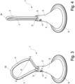
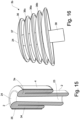
- Figs. 1 - 4 show a first embodiment of an enema nozzle 1 according to the invention.
- Said nozzle consists basically of a catheter 2, a retention member 3 in the form of an expandable loop 7, and a restriction unit 4.
- the catheter 2 comprises a substantially elongate tubular part 5 defining an insertion body, and a proximal end that extends into a flared funnel-shaped part 6 via a smooth transition.
- the restriction unit 4 is defined by an internal channel 8 of the catheter 2 which extends into a distal opening 9, and wherein the retention member 3 is arranged for being movably in and/or out of said internal channel 8 such that the retention member 3 projects from and/or withdraws into the distal opening 9 of the catheter 2 by means of a control unit 10, which in the embodiment shown comprises a cylinder 11.
- the two ends 12,13 of the expandable loop 8 is attached to the cylinder 11's distal end 14, and the proximal end 15 of the cylinder is arranged for being connected to an enema reservoir and/or enema pump via conventional coupling means, e.g. a snap fitting.
- Said cylinder 11 comprises two first delivery openings 16, which in a position of administering the enema, i.e. when the expandable loop 7 is placed in the extended form as shown in fig. 3 , will be in fluid communication with two corresponding second delivery openings 17 for delivering the enema to the rectum/colon.
- the an expandable loop 7 is in its compact form, as shown in fig. 1 and 2 , placed inside the internal channel 8 forcing the loop 7 into a folded form, i.e. into a compact form where the longitudinal axis of the loop is parallel with the longitudinal axis of the catheter.
- the tip 18 of the loop 7 extends out of the distal opening 9 of the internal channel 8 thereby providing a flexible insertion tip i.e. a tip which is softer, more elastic, and more flexible, than the catheter 2, whereby said flexible tip 18 may deform and/or flex in response to deformations and obstacles, during insertion into the rectum and colon.
- said loop 7 also could be placed entirely inside the internal channel 8.
- the catheter 2 can easily be inserted into the rectum or other body cavity without risking damage to the rectum and/or colon wall.
- the user can advances the cylinder 11 towards the distal opening 9, e.g. by manually displacing the cylinder 11 (or a tubing connected to said cylinder), thereby axially displacing the cylinder 11 inside the internal channel 9 in the longitudinal direction of the catheter 2, where after the loop 7 projects from the distal opening 9.
- the expandable loop 7 is made of an elastic material with a shape memory the expandable loop 7 will automatically expand into a loop shape, as shown in fig. 3 , by its own elasticity ensuring that the enema nozzle 1 is retained in the body cavity.
- the largest dimension of retention member i.e. the largest direct distance X between the two points Z 1 , Z 2 longest from each other, is more than five times the largest diameter (direct distance) x of the tip of catheter 2.
- the loop 7 can either be pulled back into the internal channel 8 returning to the position shown in fig. 1 , by retracting the cylinder 11, or the user can by means of the inherent elasticity of the loop 7 simply pull the enema nozzle 1 out of the rectum, during which the loop 7 will fold in upon itself, as shown in fig. 4 , due to the elastic nature of the loop.
- Fig. 5 shows a second embodiment of the enema nozzle 1' according to the present invention.
- Said embodiment corresponds to the embodiment shown in fig. 1 - 4 , and for like parts the same reference numbers are used.
- the expandable loop 7 of the second embodiment is a hollow tube 19 arranged for delivering the enema via one or more third delivery openings 20 placed in the side wall of said tube.
- the tube comprise three third delivery openings 13.
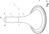
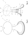
- Figs. 6 - 9 show a third embodiment of the enema nozzle 1" according to the present invention. Said embodiment corresponds to the embodiment shown in fig. 1 - 4 , and for like parts the same reference numbers are used.
- the expandable loop 7 is substituted with a resilient compressible foam body 21 which can be moved out of the internal channel 8 of the catheter 2 in response to an operation of the control unit 10.
- the foam body 21 is made of a compressible material which is compressed by the inner walls 22 of the internal channel 8, as shown in fig. 9 , and which automatically will expand when it is forced out of the internal channel 8 e.g. when it comes into contact with a liquid, e.g. the body fluids/humidity in the body cavity.
- a liquid e.g. the body fluids/humidity in the body cavity.
- the foam body 21 is partly out of the internal channel 8, and in fig. 8 and fig. 9 the foam body 21 is placed in the fully expanded position, where the largest direct distance Y (diameter) of the retention member is above four to five times the diameter y of the tip of the catheter 2. As is best seen in fig.
- the enema flow channel 23 that extends through the cylinder 11 of the control unit 10 ends in a delivery opening 24 at the distal end 25 (top) of the foam body 21.
- the flow channel may be terminated inside the foam body 21 for delivering the enema via the porous structure of the foam body.
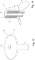
- the restriction unit 4 is made of a thin cover 26 of a biodegradable material that will rapidly dissolve and/or disintegrate upon contact with a liquid/humidity.
- Said cover 26 is placed over the retention member 3 which as shown in fig. 11 is arranged on the outer surface 27 of the catheter 2, such that the outer circumference of the retention member 3 in its compact form is substantially the same as the outer circumference of the catheter 2.
- the retention member is a foam body 31 which automatically will expand when it comes into contact with a liquid, e.g. the body fluids/humidity in the body cavity.
- the cover 26 restricts the size of the foam body 31, thereby providing an easy insertion without any discomfort due to extending and/or protection parts. Since it is preferred that the biodegradable cover 26 is dissolved/disintegrated and the foam body 31 is placed in the expanded form in less than two minutes, preferably less than one minute, the cover 26 comprises an small aperture 28 at the distal end of the cover, allowing the enema liquid to be expelled from said aperture 28, via the flow channel 29 and delivery opening 30 whereby the enema liquid may assist in dissolving/dintergrating the cover 26 and/or expand the foam body 31.
- the foam body 31 may be allowed to expand to the expanded form, as shown in fig. 12 . Since the retention member is only placed in a middle section 32 of the catheter 2, the distal end 33 of the catheter 2 is not expanded.
- the enema nozzle may be stored in a gas-impermeable packaging, e.g. made of a laminate with an intermittent aluminum foil layer.
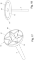
- a number of alternative retention members are shown in fig. 13 , fig. 16 - 18 . Said retention members correspond to the retention members discussed earlier and for like parts, the same reference numbers are use.
- the retention members can further all be placed in the compact form using a restriction unit corresponding to the restriction unit shown in fig. 1 - 9 , i.e. a restriction unit defined by an internal channel of the catheter which extends into a distal opening, and wherein the retention member is arranged for being movably in and/or out of said internal channel e.g. by means of a control unit, or a biodegradable restriction unit e.g. as discussed in fig. 10 - 12 , i.e. a unit made of biodegradable material that will rapidly dissolve and/or disintegrate upon contact with a liquid/humidity.
- a restriction unit corresponding to the restriction unit shown in fig. 1 - 9
- a restriction unit defined by an internal channel of the catheter which extends into a distal opening
- the retention member is arranged for being movably in and/or out of said internal channel e.g. by means of a control unit, or a biodegradable restriction unit e.g. as
- Fig. 13 show a first alternative embodiment of a retention member 3a in the form of a foam body comprising a single disc 34, arranged such that said retention member 3a in the expanded form have an umbrella/mushroom shape wherein the disc 34 represents the canopy/cap and the catheter 2 the stem.
- the retention member 3a of fig. 13 is placed in the compact form by a restriction unit 4 defined by an internal channel 8 of the catheter 2 which extends into a distal opening 9, and wherein the retention member 3a is arranged for being movably in and/or out of said internal channel 8 such that the retention member 3a projects from and/or withdraws into the distal opening 9 of the catheter 2 by means of a control unit (not shown), but the control unit may e.g. correspond to the control unit of fig. 1 -4 .
- the disc 34 is in the compact form folded and pressed against the inner side of the restriction unit 4, and an enema flow channel 23 extends through the catheter/restriction unit 4, and ends in a delivery opening 24 at the distal end (top) of the disc 34.
- the retention member 3a could alternatively be retained by a restriction unit 4 in the form of a small band 35 that holds the disc 34 in a folded compact form parallel with the outer side of the catheter 2, as shown in fig. 15 .
- Said band 35 is made of a biodegradable material that will dissolve and/or disintegrate upon contact with a liquid/humidity.
- the band 35 Before and during insertion the band 35 restricts the size of the retention member 3a, thereby providing an easy insertion without any discomfort due to extending and/or protection parts. Once the band 35 is dissolved/disintegrated the retention member 3a may be allowed to expand to the expanded form, as shown in fig. 13 .
- the disc 34 will automatically expand axially in an outwardly direction to place the retention member in the expanded form shown in fig. 13 .
- the retention member 3a can be made of any suitable material, e.g. foam or an elastomeric polymer.
- the retention member 3b comprises a number of circular discs 36, and wherein the diameter of each discs (starting form the distal end 37 of the retention member) increases gradually towards the proximal end 38.
- a disc 36a in the middle section of the retention member will have a diameter which is slightly smaller than the disc 36b placed below, but larger than the disc 36c placed above.
- the retention member 3b has a shape resembling a Christmas-tree.
- the retention member 3b comprises five discs, but said number may be higher or lower if considered relevant.
- the discs 36 of the retention member 3b may be restricted and expanded in a similar way as discussed for the embodiment 3a, and shown in fig. 14 and 15 .
- the retention member 3c is in the form of an inverted soft cone 37, e.g. made of a form, with a cut away section 38 in the form of a star. Said cut-away section 38 ensures that the inverted soft cone both can be placed in the compact form during insertion and that it can collapse during removal. The inverted soft cone will both provide an efficient seal with the colon wall and feel comfortable for the user.
- the discs 36 may be of either a foam material and/or an elastomeric polymer, in either case it will provides a seal with the colon wall when placed in the expanded form.
- One or more delivery openings may be provided between the discs.
- the inverted soft cone 37 may be restricted and expanded in a similar way as discussed for the embodiment 3a, and shown in fig. 14 and 15 .
- the embodiment 3d shown in fig. 18 corresponds to the embodiment 3b shown in fig. 13 , but here the disc 39 consist of a thin (about 1 - 5 mm) canopy 40 made of a flexible elastomeric material with a soft foam ring 41 placed along the entire circumferences.
- the soft ring 41 will provides a tight fit with the colon wall and efficiently prevent premature and unwanted leakage of fluid and fecal matter from the anus during an irrigation session.
- the thin canopy 40 will ensure that the retention member 3d easily can be placed in the compact form, where it will take up very little space, or expanded form, but also that it easily will fold upwards, when the enema device is pulled out, or the retention member is retracted into the restriction unit (internal channel of the catheter).
- the retention member 3d may be restricted and expanded in a similar way as discussed for the embodiment 3a, and shown in fig. 14 and 15 .
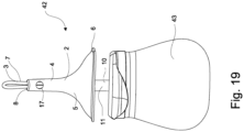
- Fig. 19 shows an enema system 42 according to the invention, wherein the enema nozzle shown in fig. 1 - 4 is connected to a substantially bulb-formed enema delivery container 43, arranged for containing the enema.
- the enema is administered by squeezing the delivery container 43 one or more times, depending on the desired dosage.
- the enema system 42 may comprises a one-way valve (not shown) that effectively will prevent backflow of liquid and faeces from the colon and/or rectum into the device and said one-way valve will therefore preclude any contamination of the delivery container 43 and it's remaining content, which may occur after administration of the enema to a patient.
- the delivery container can easily be used for several applications, e.g. by refilling the container with a second dose of the same - or a different - enema (liquid).
- the enema nozzle 1 may be removable connected to the delivery container by means of a coupling (not shown) . Thereby can the enema nozzle be a disposable nozzle or the nozzle can be individually cleaned and/or sterilised.
- the delivery container may be reused several times.
- the enema nozzles disclosed herein may also be used for larger irrigations systems wherein the enema nozzle is connected to the enema reservoir via a relatively long delivery tube, and wherein the irrigation system e.g. comprises pumping means, control means, collection means for the stool, etc.
- the irrigation system e.g. comprises pumping means, control means, collection means for the stool, etc.
Landscapes
- Health & Medical Sciences (AREA)
- Life Sciences & Earth Sciences (AREA)
- Animal Behavior & Ethology (AREA)
- Engineering & Computer Science (AREA)
- Anesthesiology (AREA)
- Biomedical Technology (AREA)
- Heart & Thoracic Surgery (AREA)
- Hematology (AREA)
- General Health & Medical Sciences (AREA)
- Public Health (AREA)
- Veterinary Medicine (AREA)
- Pulmonology (AREA)
- Biophysics (AREA)
- Infusion, Injection, And Reservoir Apparatuses (AREA)
Claims (19)
- Einlaufdüse (1, 1', 1", 1‴) für ein Einlaufsystem (34), und wobei die Einlaufdüse (1, 1', 1'', 1‴) einen Katheter (2) umfasst, der mit einem Rückhalteelement (3) versehen ist, wobei das Rückhalteelement (3) so angeordnet ist, dass es während des Einführens in eine Körperhöhle in eine kompakte Form gebracht wird und nach dem Einführen in eine expandierte Form gebracht wird, um die Einlaufdüse (1, 1', 1", 1‴) in der Körperhöhle zurückzuhalten, und wobei die Einlaufdüse (1, 1', 1", 1‴) ferner eine Begrenzungseinheit (4) umfasst, die so angeordnet ist, dass sie das Rückhalteelement (3) während des Einführens in seine kompakte Form bringt, und wobei die Begrenzungseinheit so angeordnet ist, dass sie das Rückhalteelement während des Einführens in die Körperhöhle zumindest teilweise umgibt/umschließt, und
dadurch gekennzeichnet, dass
die Einlaufdüse ein Einwegventil umfasst, das so angeordnet ist, dass es einen Rückfluss in die Einlaufdüse verhindert. - Einlaufdüse (1, 1', 1", 1‴) nach Anspruch 1, wobei die Begrenzungseinheit (4) und das Rückhalteelement (3) so angeordnet sind, dass sie in Bezug zueinander verschoben werden, nachdem die Einlaufdüse in die Körperhöhle eingeführt wurde, und/oder die Begrenzungseinheit so konfiguriert ist, dass sie zumindest teilweise aus dem Rückhalteelement entfernt wird, nachdem die Einlaufdüse in die Körperhöhle eingeführt wurde, wodurch das Rückhalteelement (3) expandieren kann, um die Einlaufdüse in der Körperhöhle zurückzuhalten.
- Einlaufdüse (1, 1', 1", 1‴) nach einem der vorhergehenden Ansprüche, wobei die Begrenzungseinheit (4) so angeordnet ist, dass sie das Rückhalteelement (3) an die Form und/oder Abmessungen des Katheters (2) anpasst, wenn sich das Rückhalteelement (3) in der kompakten Form befindet; und/oder um zu verhindern, dass sich das Rückhalteelement (3) von der ringförmigen äußeren Längsseite/-fläche des Katheters (2) erstreckt und/oder vorsteht.
- Einlaufdüse (1, 1', 1", 1‴) nach einem der vorhergehenden Ansprüche, wobei der Außenumfang des Rückhalteelements (3) in seiner kompakten Form derselbe, im Wesentlichen derselbe oder kleiner als der Außenumfang des Katheters (2) ist.
- Einlaufdüse (1, 1', 1", 1‴) nach einem der vorhergehenden Ansprüche, wobei das Rückhalteelement (3) kein Ballon ist, der so angeordnet ist, dass er mit Luft oder Flüssigkeit aufgeblasen wird.
- Einlaufdüse (1, 1', 1", 1‴) nach einem der vorhergehenden Ansprüche, wobei das Rückhalteelement (3) in seiner kompakten Form parallel zur Längsachse des Katheters (2) angeordnet ist und sich in seiner expandierten Form von dem Katheter (2) nach außen erstreckt.
- Einlaufdüse (1, 1', 1", 1‴) nach einem der vorhergehenden Ansprüche, wobei das Rückhalteelement (3) und der Katheter (2) unterschiedliche Elemente sind.
- Einlaufdüse (1, 1', 1", 1‴) nach einem der vorhergehenden Ansprüche, wobei die Begrenzungseinheit (4) so konfiguriert ist, dass sich das Rückhalteelement (3) zumindest nicht vollständig expandiert, bis der Katheter im Wesentlichen vollständig eingeführt ist.
- Einlaufdüse (1‴) nach einem der vorhergehenden Ansprüche, wobei das Rückhalteelement (3) eine oder mehrere expandierbare Strukturen (31) umfasst, die so angeordnet sind, dass sie in der kompakten Form mittels der Begrenzungseinheit (26, 35) um eine Außenfläche des Katheters (2) gefaltet oder platziert werden.
- Einlaufdüse (1, 1', 1‴) nach einem der Ansprüche 1 - 8, wobei die Begrenzungseinheit (4) ein Innenkanal (8) in dem Katheter (2) ist und wobei das Rückhalteelement (3) so angeordnet ist, dass es in den und/oder aus dem Innenkanal (8) beweglich ist, so dass das Rückhalteelement (3) von einer distalen Öffnung (9) des Katheters (2) vorsteht und/oder sich in diese zurückzieht.
- Einlaufdüse (1, 1', 1‴) nach einem der vorhergehenden Ansprüche, wobei die Einlaufdüse (1, 1', 1", 1ʺʺ) eine Steuereinheit (10) umfasst, die so angeordnet ist, dass sie in einer ersten Position das Rückhalteelement (3) in der kompakten Form platziert und in einer zweiten Position das Rückhalteelement (3) in der expandierten Form platziert.
- Einlaufdüse (1, 1', 1‴) nach Anspruch 11, wenn abhängig von Anspruch 10, wobei die Steuereinheit (10) einen Zylinder (11) umfasst, der so angeordnet ist, dass er in dem Innenkanal (8) in Längsrichtung des Katheters (2) axial verschoben wird, und wobei die Steuereinheit (10) vorzugsweise einen Innenkanal (11) umfasst, in dem eine oder mehrere fluidzuführende Öffnungen (16) angeordnet sind, die in Fluidverbindung mit einer ersten oder zweiten Seitenwand (17) des Katheters (2) stehen, und wobei die eine oder die mehreren fluidzuführenden Öffnungen (16) in einer ersten oder zweiten Seitenwand (16) des Katheters (2) angeordnet sind.
- Einlaufdüse (1, 1') nach einem der vorhergehenden Ansprüche, wobei das Rückhalteelement (3) vorzugsweise aus einem elastischen Material besteht, das eine Form aufweist.
- Einlaufdüse (1, 1') nach einem der vorhergehenden Ansprüche, wobei das Rückhalteelement (3) eine expandierbare Schlaufe (8) umfasst, wobei vorzugsweise die Enden (12, 13) der Schlaufe (8) an einer Steuereinheit (10) befestigt sind, so dass die Enden der Schlaufe entweder gleichzeitig oder einzeln bewegt werden können, um die Form der Schlaufe außerhalb einer distalen Öffnung des Katheters (2) zu verändern.
- Einlaufdüse (1') nach Anspruch 14, wobei die expandierbare Schlaufe eine Röhre ist, die so angeordnet ist, dass sie den Einlauf über eine oder mehrere Öffnungen (20) zuführt, die in der Seitenwand der Röhre angeordnet sind.
- Einlaufdüse (1'', 1‴) nach einem der Ansprüche 1 bis 13, wobei das Rückhalteelement (3) einen Schaumstoffkörper (21, 31) umfasst, wobei vorzugsweise der Schaumstoffkörper (21, 31) aus einem komprimierbaren Material und/oder einem Material besteht, das sich expandiert, wenn es mit einer Flüssigkeit in Kontakt kommt, und wobei vorzugsweise die Einlaufdüse so konfiguriert ist, dass der Einlauf über den Schaumstoffkörper an den Rektum/Kolon verabreicht wird.
- Einlaufdüse nach einem der Ansprüche 1 bis 13 oder Anspruch 16, wobei das Rückhalteelement (3) eine Anzahl von expandierbaren Flügeln/Armen und/oder Scheiben umfasst, die parallel zur Längsachse des Katheters (2) in der kompakten Form angeordnet sind und sich in der expandierten Form von dem Katheter (2) radial nach außen erstrecken, wobei vorzugsweise das Rückhalteelement (3) in der expandierten Form eine Form aufweist, die der Spitze eines Malecot-Katheters entspricht, und/oder wobei das Rückhalteelement (3) mindestens eine Scheibe umfasst, die in der expandierten Form einem Christbaum oder Pilzbaum entspricht.
- Einlaufdüse (1ʺʺ) nach einem der vorhergehenden Ansprüche, wobei die Begrenzungseinheit (26, 35) aus einem biologisch abbaubaren Material besteht, vorzugsweise eine dünne Abdeckung, eine Beschichtung, eine Folie, ein Band oder ein hohler zylindrischer Körper mit einer Wand, die einen inneren Hohlraum definiert, der die Größe des Rückhalteelements (31) begrenzt, wobei vorzugsweise die Begrenzungseinheit (26, 35) perforiert ist und/oder eine Anzahl von Öffnungen/Schlitzen umfasst.
- Einlaufsystem, umfassend die Einlaufdüse (1, 1', 1'', 1ʺʺ) nach einem der Ansprüche 1 bis 18.
Priority Applications (1)
| Application Number | Priority Date | Filing Date | Title |
|---|---|---|---|
| EP24159297.1A EP4364778A3 (de) | 2020-08-20 | 2021-08-20 | Selbsthaltende einlaufdüse und einlaufsystem mit dieser einlaufdüse |
Applications Claiming Priority (2)
| Application Number | Priority Date | Filing Date | Title |
|---|---|---|---|
| DKPA202070539A DK181106B1 (en) | 2020-08-20 | 2020-08-20 | A self-retaining enema nozzle and an enema system comprising said enema nozzle |
| PCT/EP2021/073147 WO2022038268A1 (en) | 2020-08-20 | 2021-08-20 | A self-retaining enema nozzle and an enema system comprising said enema nozzle. |
Related Child Applications (1)
| Application Number | Title | Priority Date | Filing Date |
|---|---|---|---|
| EP24159297.1A Division EP4364778A3 (de) | 2020-08-20 | 2021-08-20 | Selbsthaltende einlaufdüse und einlaufsystem mit dieser einlaufdüse |
Publications (3)
| Publication Number | Publication Date |
|---|---|
| EP4199991A1 EP4199991A1 (de) | 2023-06-28 |
| EP4199991C0 EP4199991C0 (de) | 2024-03-20 |
| EP4199991B1 true EP4199991B1 (de) | 2024-03-20 |
Family
ID=80284804
Family Applications (2)
| Application Number | Title | Priority Date | Filing Date |
|---|---|---|---|
| EP24159297.1A Pending EP4364778A3 (de) | 2020-08-20 | 2021-08-20 | Selbsthaltende einlaufdüse und einlaufsystem mit dieser einlaufdüse |
| EP21765910.1A Active EP4199991B1 (de) | 2020-08-20 | 2021-08-20 | Selbsthaltende einlaufdüse und einlaufsystem mit dieser einlaufdüse |
Family Applications Before (1)
| Application Number | Title | Priority Date | Filing Date |
|---|---|---|---|
| EP24159297.1A Pending EP4364778A3 (de) | 2020-08-20 | 2021-08-20 | Selbsthaltende einlaufdüse und einlaufsystem mit dieser einlaufdüse |
Country Status (5)
| Country | Link |
|---|---|
| US (1) | US11938293B2 (de) |
| EP (2) | EP4364778A3 (de) |
| CN (1) | CN116096450B (de) |
| DK (1) | DK181106B1 (de) |
| WO (1) | WO2022038268A1 (de) |
Families Citing this family (5)
| Publication number | Priority date | Publication date | Assignee | Title |
|---|---|---|---|---|
| DK181888B1 (en) * | 2023-03-08 | 2025-03-06 | Qufora As | An enema nozzle, an enema device comprising said enema nozzle, a method of manufacturing the enema nozzle, and a method of assembling the enema nozzle |
| USD1071152S1 (en) * | 2023-04-27 | 2025-04-15 | Coloplast A/S | Anal irrigation cone |
| CN117138204B (zh) * | 2023-09-08 | 2025-07-29 | 安徽省幸福工场医疗设备有限公司 | 医用鞘管、输尿管导引鞘及输尿管手术系统 |
| CN118750678A (zh) * | 2024-08-02 | 2024-10-11 | 重庆医科大学附属第三医院(捷尔医院) | 一种具有压力检测功能的回肠造口灌肠装置 |
| DK202430523A1 (en) * | 2024-09-06 | 2026-03-10 | Qufora As | An enema nozzle and an enema device comprising said enema nozzle. |
Family Cites Families (13)
| Publication number | Priority date | Publication date | Assignee | Title |
|---|---|---|---|---|
| US2483851A (en) * | 1946-09-19 | 1949-10-04 | Smith Charles Victor | Syringe |
| US5074842A (en) | 1990-07-20 | 1991-12-24 | Clayton Ralph S | Scheduled bowel management system |
| ES2225991T3 (es) * | 1996-11-27 | 2005-03-16 | Coloplast A/S | Dispositivo de irrigacion. |
| AU2003226940A1 (en) | 2002-07-12 | 2004-02-02 | Coloplast A/S | Irrigation system |
| WO2009015152A1 (en) * | 2007-07-22 | 2009-01-29 | C.R. Bard, Inc. | Waste management system |
| CN201076631Y (zh) * | 2007-09-21 | 2008-06-25 | 常显德 | 一次性便携式灌肠器 |
| WO2010020985A1 (en) * | 2008-08-18 | 2010-02-25 | Torus Medical Ltd | An inflatable rectal sleeve device and method |
| US8579850B2 (en) | 2009-08-26 | 2013-11-12 | Mbh-International A/S | Irrigation device and method of using the device |
| EP3532126B1 (de) * | 2016-10-28 | 2021-03-10 | MBH-International A/S | Anordnung mit katheter und kopplungskomponente zur kopplung des katheters an rohre, und vorrichtung umfassend eine solche anordnung |
| GB2563933A (en) | 2017-06-30 | 2019-01-02 | Aquaflush Medical Ltd | Improved nozzle and anal irrigation system |
| EP4249012A3 (de) * | 2017-08-24 | 2023-12-06 | Hollister Incorporated | Hohlorganspülsysteme |
| EP3925641A1 (de) * | 2020-06-15 | 2021-12-22 | Dentsply IH AB | Spülsystem |
| GB2596602B (en) * | 2020-07-03 | 2024-12-18 | Clinisupplies Ltd | Improved nozzle, anal irrigation system, methods of assembly and of anal irrigation |
-
2020
- 2020-08-20 DK DKPA202070539A patent/DK181106B1/en active IP Right Grant
-
2021
- 2021-08-20 EP EP24159297.1A patent/EP4364778A3/de active Pending
- 2021-08-20 US US18/041,964 patent/US11938293B2/en active Active
- 2021-08-20 WO PCT/EP2021/073147 patent/WO2022038268A1/en not_active Ceased
- 2021-08-20 EP EP21765910.1A patent/EP4199991B1/de active Active
- 2021-08-20 CN CN202180055405.3A patent/CN116096450B/zh active Active
Also Published As
| Publication number | Publication date |
|---|---|
| WO2022038268A1 (en) | 2022-02-24 |
| EP4364778A3 (de) | 2024-05-15 |
| CN116096450B (zh) | 2025-09-23 |
| EP4364778A2 (de) | 2024-05-08 |
| US11938293B2 (en) | 2024-03-26 |
| EP4199991C0 (de) | 2024-03-20 |
| US20230270932A1 (en) | 2023-08-31 |
| DK181106B1 (en) | 2022-12-21 |
| EP4199991A1 (de) | 2023-06-28 |
| DK202070539A1 (en) | 2022-02-28 |
| CN116096450A (zh) | 2023-05-09 |
Similar Documents
| Publication | Publication Date | Title |
|---|---|---|
| EP4199991B1 (de) | Selbsthaltende einlaufdüse und einlaufsystem mit dieser einlaufdüse | |
| EP1011754B1 (de) | Irrigationsvorrichtung | |
| EP2470237B1 (de) | Bewässerungsvorrichtung und verfahren zu ihrer verwendung | |
| US20070032814A1 (en) | Cervical Medical Device, System and Method | |
| EP4161608B1 (de) | Einlaufdüse und einlaufvorrichtung mit besagter einlaufdüse | |
| EP4479107B1 (de) | Einlaufdüse mit haltemitteln und einlaufsystem mit der einlaufdüse | |
| US20260108669A1 (en) | An enema nozzle and an enema device comprising said enema nozzle | |
| DK182091B1 (en) | An enema nozzle arranged for stimulating peristalsis, and an enema system comprising said enema nozzle | |
| DK202430523A1 (en) | An enema nozzle and an enema device comprising said enema nozzle. |
Legal Events
| Date | Code | Title | Description |
|---|---|---|---|
| STAA | Information on the status of an ep patent application or granted ep patent |
Free format text: STATUS: UNKNOWN |
|
| STAA | Information on the status of an ep patent application or granted ep patent |
Free format text: STATUS: THE INTERNATIONAL PUBLICATION HAS BEEN MADE |
|
| PUAI | Public reference made under article 153(3) epc to a published international application that has entered the european phase |
Free format text: ORIGINAL CODE: 0009012 |
|
| STAA | Information on the status of an ep patent application or granted ep patent |
Free format text: STATUS: REQUEST FOR EXAMINATION WAS MADE |
|
| 17P | Request for examination filed |
Effective date: 20230320 |
|
| AK | Designated contracting states |
Kind code of ref document: A1 Designated state(s): AL AT BE BG CH CY CZ DE DK EE ES FI FR GB GR HR HU IE IS IT LI LT LU LV MC MK MT NL NO PL PT RO RS SE SI SK SM TR |
|
| DAV | Request for validation of the european patent (deleted) | ||
| DAX | Request for extension of the european patent (deleted) | ||
| GRAP | Despatch of communication of intention to grant a patent |
Free format text: ORIGINAL CODE: EPIDOSNIGR1 |
|
| STAA | Information on the status of an ep patent application or granted ep patent |
Free format text: STATUS: GRANT OF PATENT IS INTENDED |
|
| RAP3 | Party data changed (applicant data changed or rights of an application transferred) |
Owner name: QUFORA A/S |
|
| INTG | Intention to grant announced |
Effective date: 20240109 |
|
| GRAS | Grant fee paid |
Free format text: ORIGINAL CODE: EPIDOSNIGR3 |
|
| GRAA | (expected) grant |
Free format text: ORIGINAL CODE: 0009210 |
|
| STAA | Information on the status of an ep patent application or granted ep patent |
Free format text: STATUS: THE PATENT HAS BEEN GRANTED |
|
| AK | Designated contracting states |
Kind code of ref document: B1 Designated state(s): AL AT BE BG CH CY CZ DE DK EE ES FI FR GB GR HR HU IE IS IT LI LT LU LV MC MK MT NL NO PL PT RO RS SE SI SK SM TR |
|
| REG | Reference to a national code |
Ref country code: GB Ref legal event code: FG4D |
|
| REG | Reference to a national code |
Ref country code: CH Ref legal event code: EP |
|
| REG | Reference to a national code |
Ref country code: IE Ref legal event code: FG4D |
|
| REG | Reference to a national code |
Ref country code: DE Ref legal event code: R096 Ref document number: 602021010739 Country of ref document: DE |
|
| U01 | Request for unitary effect filed |
Effective date: 20240418 |
|
| U07 | Unitary effect registered |
Designated state(s): AT BE BG DE DK EE FI FR IT LT LU LV MT NL PT SE SI Effective date: 20240424 |
|
| PG25 | Lapsed in a contracting state [announced via postgrant information from national office to epo] |
Ref country code: GR Free format text: LAPSE BECAUSE OF FAILURE TO SUBMIT A TRANSLATION OF THE DESCRIPTION OR TO PAY THE FEE WITHIN THE PRESCRIBED TIME-LIMIT Effective date: 20240621 |
|
| PG25 | Lapsed in a contracting state [announced via postgrant information from national office to epo] |
Ref country code: HR Free format text: LAPSE BECAUSE OF FAILURE TO SUBMIT A TRANSLATION OF THE DESCRIPTION OR TO PAY THE FEE WITHIN THE PRESCRIBED TIME-LIMIT Effective date: 20240320 Ref country code: RS Free format text: LAPSE BECAUSE OF FAILURE TO SUBMIT A TRANSLATION OF THE DESCRIPTION OR TO PAY THE FEE WITHIN THE PRESCRIBED TIME-LIMIT Effective date: 20240620 |
|
| PG25 | Lapsed in a contracting state [announced via postgrant information from national office to epo] |
Ref country code: RS Free format text: LAPSE BECAUSE OF FAILURE TO SUBMIT A TRANSLATION OF THE DESCRIPTION OR TO PAY THE FEE WITHIN THE PRESCRIBED TIME-LIMIT Effective date: 20240620 Ref country code: NO Free format text: LAPSE BECAUSE OF FAILURE TO SUBMIT A TRANSLATION OF THE DESCRIPTION OR TO PAY THE FEE WITHIN THE PRESCRIBED TIME-LIMIT Effective date: 20240620 Ref country code: HR Free format text: LAPSE BECAUSE OF FAILURE TO SUBMIT A TRANSLATION OF THE DESCRIPTION OR TO PAY THE FEE WITHIN THE PRESCRIBED TIME-LIMIT Effective date: 20240320 Ref country code: GR Free format text: LAPSE BECAUSE OF FAILURE TO SUBMIT A TRANSLATION OF THE DESCRIPTION OR TO PAY THE FEE WITHIN THE PRESCRIBED TIME-LIMIT Effective date: 20240621 |
|
| PG25 | Lapsed in a contracting state [announced via postgrant information from national office to epo] |
Ref country code: IS Free format text: LAPSE BECAUSE OF FAILURE TO SUBMIT A TRANSLATION OF THE DESCRIPTION OR TO PAY THE FEE WITHIN THE PRESCRIBED TIME-LIMIT Effective date: 20240720 |
|
| U20 | Renewal fee for the european patent with unitary effect paid |
Year of fee payment: 4 Effective date: 20240902 |
|
| PG25 | Lapsed in a contracting state [announced via postgrant information from national office to epo] |
Ref country code: SM Free format text: LAPSE BECAUSE OF FAILURE TO SUBMIT A TRANSLATION OF THE DESCRIPTION OR TO PAY THE FEE WITHIN THE PRESCRIBED TIME-LIMIT Effective date: 20240320 |
|
| PG25 | Lapsed in a contracting state [announced via postgrant information from national office to epo] |
Ref country code: ES Free format text: LAPSE BECAUSE OF FAILURE TO SUBMIT A TRANSLATION OF THE DESCRIPTION OR TO PAY THE FEE WITHIN THE PRESCRIBED TIME-LIMIT Effective date: 20240320 |
|
| PG25 | Lapsed in a contracting state [announced via postgrant information from national office to epo] |
Ref country code: CZ Free format text: LAPSE BECAUSE OF FAILURE TO SUBMIT A TRANSLATION OF THE DESCRIPTION OR TO PAY THE FEE WITHIN THE PRESCRIBED TIME-LIMIT Effective date: 20240320 |
|
| PG25 | Lapsed in a contracting state [announced via postgrant information from national office to epo] |
Ref country code: PL Free format text: LAPSE BECAUSE OF FAILURE TO SUBMIT A TRANSLATION OF THE DESCRIPTION OR TO PAY THE FEE WITHIN THE PRESCRIBED TIME-LIMIT Effective date: 20240320 |
|
| PG25 | Lapsed in a contracting state [announced via postgrant information from national office to epo] |
Ref country code: SK Free format text: LAPSE BECAUSE OF FAILURE TO SUBMIT A TRANSLATION OF THE DESCRIPTION OR TO PAY THE FEE WITHIN THE PRESCRIBED TIME-LIMIT Effective date: 20240320 |
|
| PG25 | Lapsed in a contracting state [announced via postgrant information from national office to epo] |
Ref country code: SM Free format text: LAPSE BECAUSE OF FAILURE TO SUBMIT A TRANSLATION OF THE DESCRIPTION OR TO PAY THE FEE WITHIN THE PRESCRIBED TIME-LIMIT Effective date: 20240320 Ref country code: SK Free format text: LAPSE BECAUSE OF FAILURE TO SUBMIT A TRANSLATION OF THE DESCRIPTION OR TO PAY THE FEE WITHIN THE PRESCRIBED TIME-LIMIT Effective date: 20240320 Ref country code: RO Free format text: LAPSE BECAUSE OF FAILURE TO SUBMIT A TRANSLATION OF THE DESCRIPTION OR TO PAY THE FEE WITHIN THE PRESCRIBED TIME-LIMIT Effective date: 20240320 Ref country code: PL Free format text: LAPSE BECAUSE OF FAILURE TO SUBMIT A TRANSLATION OF THE DESCRIPTION OR TO PAY THE FEE WITHIN THE PRESCRIBED TIME-LIMIT Effective date: 20240320 Ref country code: IS Free format text: LAPSE BECAUSE OF FAILURE TO SUBMIT A TRANSLATION OF THE DESCRIPTION OR TO PAY THE FEE WITHIN THE PRESCRIBED TIME-LIMIT Effective date: 20240720 Ref country code: ES Free format text: LAPSE BECAUSE OF FAILURE TO SUBMIT A TRANSLATION OF THE DESCRIPTION OR TO PAY THE FEE WITHIN THE PRESCRIBED TIME-LIMIT Effective date: 20240320 Ref country code: CZ Free format text: LAPSE BECAUSE OF FAILURE TO SUBMIT A TRANSLATION OF THE DESCRIPTION OR TO PAY THE FEE WITHIN THE PRESCRIBED TIME-LIMIT Effective date: 20240320 |
|
| REG | Reference to a national code |
Ref country code: DE Ref legal event code: R026 Ref document number: 602021010739 Country of ref document: DE |
|
| PLBI | Opposition filed |
Free format text: ORIGINAL CODE: 0009260 |
|
| PLAB | Opposition data, opponent's data or that of the opponent's representative modified |
Free format text: ORIGINAL CODE: 0009299OPPO |
|
| PLAX | Notice of opposition and request to file observation + time limit sent |
Free format text: ORIGINAL CODE: EPIDOSNOBS2 |
|
| 26 | Opposition filed |
Opponent name: COLOPLAST A/S Effective date: 20241220 |
|
| R26 | Opposition filed (corrected) |
Opponent name: COLOPLAST A/S Effective date: 20241220 |
|
| REG | Reference to a national code |
Ref country code: CH Ref legal event code: PL |
|
| PG25 | Lapsed in a contracting state [announced via postgrant information from national office to epo] |
Ref country code: MC Free format text: LAPSE BECAUSE OF FAILURE TO SUBMIT A TRANSLATION OF THE DESCRIPTION OR TO PAY THE FEE WITHIN THE PRESCRIBED TIME-LIMIT Effective date: 20240320 Ref country code: CH Free format text: LAPSE BECAUSE OF NON-PAYMENT OF DUE FEES Effective date: 20240831 |
|
| PLBB | Reply of patent proprietor to notice(s) of opposition received |
Free format text: ORIGINAL CODE: EPIDOSNOBS3 |
|
| U20 | Renewal fee for the european patent with unitary effect paid |
Year of fee payment: 5 Effective date: 20250901 |
|
| PGFP | Annual fee paid to national office [announced via postgrant information from national office to epo] |
Ref country code: GB Payment date: 20250819 Year of fee payment: 5 |
|
| PLAB | Opposition data, opponent's data or that of the opponent's representative modified |
Free format text: ORIGINAL CODE: 0009299OPPO |
|
| PGFP | Annual fee paid to national office [announced via postgrant information from national office to epo] |
Ref country code: IE Payment date: 20250819 Year of fee payment: 5 |
|
| R26 | Opposition filed (corrected) |
Opponent name: COLOPLAST A/S Effective date: 20241220 |
|
| PG25 | Lapsed in a contracting state [announced via postgrant information from national office to epo] |
Ref country code: CY Free format text: LAPSE BECAUSE OF FAILURE TO SUBMIT A TRANSLATION OF THE DESCRIPTION OR TO PAY THE FEE WITHIN THE PRESCRIBED TIME-LIMIT; INVALID AB INITIO Effective date: 20210820 |
|
| PG25 | Lapsed in a contracting state [announced via postgrant information from national office to epo] |
Ref country code: HU Free format text: LAPSE BECAUSE OF FAILURE TO SUBMIT A TRANSLATION OF THE DESCRIPTION OR TO PAY THE FEE WITHIN THE PRESCRIBED TIME-LIMIT; INVALID AB INITIO Effective date: 20210820 |
|
| RDAF | Communication despatched that patent is revoked |
Free format text: ORIGINAL CODE: EPIDOSNREV1 |