EP4199775B1 - Mittelfussstützstrukturen für schuhwerk - Google Patents
Mittelfussstützstrukturen für schuhwerk Download PDFInfo
- Publication number
- EP4199775B1 EP4199775B1 EP21769249.0A EP21769249A EP4199775B1 EP 4199775 B1 EP4199775 B1 EP 4199775B1 EP 21769249 A EP21769249 A EP 21769249A EP 4199775 B1 EP4199775 B1 EP 4199775B1
- Authority
- EP
- European Patent Office
- Prior art keywords
- support member
- lateral
- midfoot support
- footwear
- medial
- Prior art date
- Legal status (The legal status is an assumption and is not a legal conclusion. Google has not performed a legal analysis and makes no representation as to the accuracy of the status listed.)
- Active
Links
Images


Classifications
-
- A—HUMAN NECESSITIES
- A43—FOOTWEAR
- A43B—CHARACTERISTIC FEATURES OF FOOTWEAR; PARTS OF FOOTWEAR
- A43B23/00—Uppers; Boot legs; Stiffeners; Other single parts of footwear
- A43B23/22—Supports for the shank or arch of the uppers
- A43B23/222—Supports for the shank or arch of the uppers characterised by the attachment to the sole
-
- A—HUMAN NECESSITIES
- A43—FOOTWEAR
- A43B—CHARACTERISTIC FEATURES OF FOOTWEAR; PARTS OF FOOTWEAR
- A43B13/00—Soles; Sole-and-heel integral units
- A43B13/02—Soles; Sole-and-heel integral units characterised by the material
- A43B13/12—Soles with several layers of different materials
- A43B13/125—Soles with several layers of different materials characterised by the midsole or middle layer
-
- A—HUMAN NECESSITIES
- A43—FOOTWEAR
- A43B—CHARACTERISTIC FEATURES OF FOOTWEAR; PARTS OF FOOTWEAR
- A43B13/00—Soles; Sole-and-heel integral units
- A43B13/14—Soles; Sole-and-heel integral units characterised by the constructive form
- A43B13/16—Pieced soles
-
- A—HUMAN NECESSITIES
- A43—FOOTWEAR
- A43B—CHARACTERISTIC FEATURES OF FOOTWEAR; PARTS OF FOOTWEAR
- A43B13/00—Soles; Sole-and-heel integral units
- A43B13/14—Soles; Sole-and-heel integral units characterised by the constructive form
- A43B13/18—Resilient soles
- A43B13/181—Resiliency achieved by the structure of the sole
- A43B13/186—Differential cushioning region, e.g. cushioning located under the ball of the foot
-
- A—HUMAN NECESSITIES
- A43—FOOTWEAR
- A43B—CHARACTERISTIC FEATURES OF FOOTWEAR; PARTS OF FOOTWEAR
- A43B13/00—Soles; Sole-and-heel integral units
- A43B13/14—Soles; Sole-and-heel integral units characterised by the constructive form
- A43B13/18—Resilient soles
- A43B13/20—Pneumatic soles filled with a compressible fluid, e.g. air, gas
-
- A—HUMAN NECESSITIES
- A43—FOOTWEAR
- A43B—CHARACTERISTIC FEATURES OF FOOTWEAR; PARTS OF FOOTWEAR
- A43B3/00—Footwear characterised by the shape or the use
- A43B3/06—Shoes with flaps; Footwear with divided uppers
-
- A—HUMAN NECESSITIES
- A43—FOOTWEAR
- A43B—CHARACTERISTIC FEATURES OF FOOTWEAR; PARTS OF FOOTWEAR
- A43B7/00—Footwear with health or hygienic arrangements
- A43B7/14—Footwear with health or hygienic arrangements with foot-supporting parts
- A43B7/1405—Footwear with health or hygienic arrangements with foot-supporting parts with pads or holes on one or more locations, or having an anatomical or curved form
- A43B7/1415—Footwear with health or hygienic arrangements with foot-supporting parts with pads or holes on one or more locations, or having an anatomical or curved form characterised by the location under the foot
- A43B7/142—Footwear with health or hygienic arrangements with foot-supporting parts with pads or holes on one or more locations, or having an anatomical or curved form characterised by the location under the foot situated under the medial arch, i.e. under the navicular or cuneiform bones
-
- A—HUMAN NECESSITIES
- A43—FOOTWEAR
- A43B—CHARACTERISTIC FEATURES OF FOOTWEAR; PARTS OF FOOTWEAR
- A43B7/00—Footwear with health or hygienic arrangements
- A43B7/14—Footwear with health or hygienic arrangements with foot-supporting parts
- A43B7/1405—Footwear with health or hygienic arrangements with foot-supporting parts with pads or holes on one or more locations, or having an anatomical or curved form
- A43B7/1415—Footwear with health or hygienic arrangements with foot-supporting parts with pads or holes on one or more locations, or having an anatomical or curved form characterised by the location under the foot
- A43B7/143—Footwear with health or hygienic arrangements with foot-supporting parts with pads or holes on one or more locations, or having an anatomical or curved form characterised by the location under the foot situated under the lateral arch, i.e. the cuboid bone
-
- A—HUMAN NECESSITIES
- A43—FOOTWEAR
- A43B—CHARACTERISTIC FEATURES OF FOOTWEAR; PARTS OF FOOTWEAR
- A43B7/00—Footwear with health or hygienic arrangements
- A43B7/14—Footwear with health or hygienic arrangements with foot-supporting parts
- A43B7/1405—Footwear with health or hygienic arrangements with foot-supporting parts with pads or holes on one or more locations, or having an anatomical or curved form
- A43B7/1415—Footwear with health or hygienic arrangements with foot-supporting parts with pads or holes on one or more locations, or having an anatomical or curved form characterised by the location under the foot
- A43B7/1445—Footwear with health or hygienic arrangements with foot-supporting parts with pads or holes on one or more locations, or having an anatomical or curved form characterised by the location under the foot situated under the midfoot, i.e. the second, third or fourth metatarsal
-
- A—HUMAN NECESSITIES
- A43—FOOTWEAR
- A43B—CHARACTERISTIC FEATURES OF FOOTWEAR; PARTS OF FOOTWEAR
- A43B7/00—Footwear with health or hygienic arrangements
- A43B7/14—Footwear with health or hygienic arrangements with foot-supporting parts
- A43B7/1495—Footwear with health or hygienic arrangements with foot-supporting parts with arch-supports of the bracelet type
-
- A—HUMAN NECESSITIES
- A43—FOOTWEAR
- A43B—CHARACTERISTIC FEATURES OF FOOTWEAR; PARTS OF FOOTWEAR
- A43B7/00—Footwear with health or hygienic arrangements
- A43B7/14—Footwear with health or hygienic arrangements with foot-supporting parts
- A43B7/22—Footwear with health or hygienic arrangements with foot-supporting parts with fixed flat-foot insertions, metatarsal supports, ankle flaps or the like
- A43B7/223—Footwear with health or hygienic arrangements with foot-supporting parts with fixed flat-foot insertions, metatarsal supports, ankle flaps or the like characterised by the constructive form
-
- A—HUMAN NECESSITIES
- A43—FOOTWEAR
- A43B—CHARACTERISTIC FEATURES OF FOOTWEAR; PARTS OF FOOTWEAR
- A43B13/00—Soles; Sole-and-heel integral units
- A43B13/14—Soles; Sole-and-heel integral units characterised by the constructive form
- A43B13/18—Resilient soles
- A43B13/187—Resiliency achieved by the features of the material, e.g. foam, non liquid materials
Definitions
- the present disclosure is directed to articles of footwear, and more particularly to midfoot support structures for articles of footwear.
- An article of footwear typically includes two main components: a sole structure and an upper.
- the sole structure is configured for supporting the wearer's foot and providing cushioning between the wearer's foot and the ground.
- the upper is coupled to the sole structure and is configured for securing the wearer's foot to the sole structure.
- US 6 401 366 B2 discloses an article of footwear with a midfoot support structure.
- the articles of footwear disclosed herein comprise a midfoot support structure that can provide localized support in areas of the article of footwear and/or the wearer's foot that are subjected to high forces (e.g., at the midfoot), while allowing other portions of the article of footwear to remain relatively more flexible for comfort and mobility (e.g., in the toe portion of the article of footwear).
- An article of footwear typically includes two main components: a sole structure and an upper.
- the sole structure is configured for supporting the wearer's foot and providing cushioning between the wearer's foot and the ground.
- the upper is coupled to the sole structure and forms a foot-receiving cavity.
- the upper is configured for securing the wearer's foot to the sole structure and/or can protect the wearer's foot.
- a wearer's foot In use, a wearer's foot applies various forces to the sole structure and/or the upper. These forces can vary depending on the type of use and/or the physical characteristics (e.g., size, strength) of the wearer.
- an upper of an article of footwear is made of one or more relatively thin, flexible materials. These materials allow the upper to bend and flex as the wearer moves and applies forces to the upper.
- elastically deform e.g., stretch
- some shoes have an upper with rigidity/stretchability configured for one type of movement (e.g., running forward), but it may leave the upper too stretchable for other types of movement (e.g., cutting side-to-side, jumping, stopping, and/or accelerating).
- the junction where the upper and the sole structure are secured together can be subject to relatively high forces when a wearer accelerates/decelerates and/or changes direction. This junction is sometimes referred to as "the bite line.”
- articles of footwear with controlled flexibility, improved strength, and/or increased support are desired.
- the midfoot support structure can have a lateral side portion (i.e., corresponding to the lateral or outside of a wearer's foot) and a medial side portion (i.e., corresponding to the medial or inside of a wearer's foot).
- the lateral side portion can extend "higher” (i.e., in the superior direction) than the medial side portion. This is due, at least in part, to the relatively higher forces that the lateral side of the article of footwear and/or the wearer's foot are subjected to (e.g., during lateral movements such as during a "crossover” or a "jump-stop" in a basketball activity).
- the relatively large lateral side portion of the midfoot support structure can distribute the forces across a larger area of the wearer's foot and/or away from the bite line seam of the sole structure and upper. This can, for example, improve the strength and/or comfort of the article of footwear disclosed herein compared to typical footwear.
- an article of footwear can comprise a midfoot support structure with a lateral side portion and without a medial side portion. In other examples, an article of footwear can comprise a midfoot support structure with a medial side portion and without a lateral side portion.
- An article of footwear typically includes two main components: a sole structure and an upper.
- the sole structure is configured for supporting the wearer's foot and providing cushioning between the wearer's foot and the ground.
- the upper is coupled to the sole structure and forms a foot-receiving cavity.
- the upper is configured for securing the wearer's foot to the sole structure and/or can protect the wearer's foot.
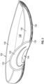
- FIGS. 1-2 depict an article of footwear 100, according to one example.
- the article of footwear 100 can also be referred to as "the article 100," “the footwear 100,” or “the shoe 100.”
- FIG. 1 depicts an elevation view of a lateral side of the article of footwear 100 (e.g., configured to be worn on a right foot of a wearer).
- FIG. 2 depicts an elevation view of a medial side of the article of footwear 100.
- the article of footwear 100 comprises a sole structure 102 and an upper 104.
- the upper 104 is coupled to and extends from the sole structure 102 thereby forming a foot-receiving cavity 106 between the sole structure 102 and the upper 104.
- the article of footwear also includes a closure system 108 to adjust the foot-receiving cavity 106.
- the closure system can be used, for example, to secure/release the article of footwear 100 to/from a wearer's foot.
- Exemplary closure systems include laces, straps, bands, cables, cords, ratcheting mechanisms, hook-and-loop, etc.
- the article of footwear 100 can be divided into one or more portions (which can also be referred to as "zones,” "regions,” or “sections”).
- the article of footwear 100 in an anterior posterior direction, can be divided into (and/or include) a forefoot portion 110, a midfoot portion 112, and a heel portion 114.
- the forefoot portion 110 of the article of footwear 100 can correspond to anterior portions of a foot, including toes and joints connecting metatarsal bones with phalanx bones of the foot.
- the midfoot portion 112 of the article of footwear 100 can correspond with an arch area of the foot.
- the heel portion 114 of the article of footwear 100 can correspond with posterior portions of the foot, including a calcaneus bone.
- the sole structure 102 of the article of footwear 100 comprises a midsole 120, a midfoot support member 122, and an outsole 124.
- FIG. 3 depicts the sole structure 102 in an assembled configuration.
- FIG. 4 depicts the sole structure in an exploded configuration and a plurality (e.g., two) of cushioning elements 126, which are optional.
- the components of the sole structure 102 can be coupled together in various ways.
- the midsole 120, the midfoot support member 122, the outsole 124 and/or the cushioning elements 126 can be coupled together with adhesive, fasteners, stitching, over-molding, co-molding, and/or other means for coupling.
- the sole structure 102 can be coupled to the upper 104 in various ways.
- the sole structure 102 and the upper can be coupled together with adhesive, fasteners, stitching, and/or other means for coupling.
- the article of footwear 100 can include a strobel that is coupled (e.g., sewn) to an inferior portion of the upper 104, and the strobel can be coupled to the midsole 120 (e.g., via adhesive).
- the midfoot flange 132 is disposed on a lateral side of the midsole 120. Additionally or alternatively, the midsole 120 can comprise a midfoot flange on a medial side of the midsole 120. In some instances where the midsole comprises a midfoot flange on both the medial and lateral sides, the lateral flange can extend in a superior direction beyond the medial flange.
- the midfoot flange 132 can comprise various shapes taken in a plane perpendicular to an anterior/posterior direction of the article of footwear 100.
- the midfoot flange 132 comprises an arcuate or a semi-annular shape in the illustrated example.
- the midfoot flange can be semi-circular, circular, elliptical, rectangular, triangular, trapezoidal, etc.
- the midsole 120 can comprise a recess 134 formed in the inferior surface of the midsole 120.
- the recess 134 can be aligned with the midfoot flange 132 such that the recess 134 is positioned under the arch of a wearer's foot.
- the recess 134 can also be configured to receive a portion of the midfoot support member 122, as further described below.
- FIGS. 5-7 depict the midfoot support member 122.
- FIG. 5 is a perspective view of the midfoot support member 122 (primarily depicting the lateral side).
- FIG. 6 is a top view of the midfoot support member 122.
- FIG. 7 is an anterior end view of the midfoot support member 122.
- the midfoot support member 122 can, for example, provide arch support to the bottom of the wearer's foot and/or can provide support to the side of the wearer's foot.
- the midfoot support member 122 can, in some examples, be formed of a relatively stiffer and/or harder material than the upper 104 and/or the midsole 120.
- the midfoot support member 122 can be formed of one or more polymeric materials such as thermoplastic polyurethane (TPU), polyamide (PA or nylon), polypropylene (PP), polyethylene (PE), acrylonitrile butadiene styrene (ABS), etc.
- the midfoot support member 122 comprises a lateral flange 136, a medial flange 138, a superior deck plate 140, and an inferior deck plate 142.
- the superior deck plate 140 and the inferior deck plate 142 extend in a medial/lateral direction from the lateral flange 136 to the medial flange 138.
- the superior deck plate 140 and the inferior deck plate 142 are spaced apart in the superior/inferior direction, thereby forming an opening 144 that extends from the lateral side of the midfoot support member 122 to the medial side of the midfoot support member 122 (see also FIGS. 1-2 ).
- the lateral flange 136 of the midfoot support member 122 extends further in the superior direction than the medial flange 138 of the midfoot support member 122.
- the medial flange 138 of the midfoot support member 122 extends further in the superior direction than the lateral flange 136 of the midfoot support member 122.
- the lateral flange 136 and the medial flange 138 can extend to the same or at least substantially the same extent in the superior direction.
- the lateral flange 136 and/or the medial flange 138 of the midfoot support member 122 can comprise various shapes taken in a plane perpendicular to the medial/lateral direction of the article of footwear 100.
- the flanges of the midfoot support member 122 comprise an arcuate or a semi-annular shape, as depicted in FIGS. 1-2 .
- the flanges can be semi-circular, circular, elliptical, rectangular, triangular, trapezoidal, etc.
- the lateral flange 136 and/or the medial flange 138 of the midfoot support member 122 can comprise various shapes taken in a plane perpendicular to the superior/inferior direction of the article of footwear 100.
- the flanges of the midfoot support member 122 flare outward in the medial/lateral direction at intermediate portions relative to anterior and posterior portions (which may be referred to herein as "convex in the anterior/posterior direction").
- the flanges can flare inward in the medial/lateral direction at the intermediate portions relative to anterior and posterior portions (which may be referred to herein as "concave in the anterior/posterior direction").
- the medial flange 138 is angled or tapered outwardly in the medial direction such that the superior portion is disposed medial to the inferior portion.
- the flanges can be angled or tapered such that inferior portions of the flanges extend farther in the medial/lateral direction than superior portions of the flanges.
- the flanges can be straight or at least substantially straight in the superior/inferior direction (e.g., vertical).
- the midfoot support member 122 comprises one or more mating elements configured to receiving one or more cushioning elements.
- the midfoot support member 122 comprises an anterior recess 146 and a posterior recess 148, which are configured for receiving the cushioning elements 126, as depicted in FIG. 4 .
- the anterior edges of the deck plates and the interior surfaces of the flanges can define the anterior recess 146.
- the posterior edges of the deck plates and the interior surfaces of the flanges can define the posterior recess 148.
- the sole structure can include one or more additional components (e.g., one or more additional cushioning elements) and/or omit one or more of the components of the sole structure (e.g., there may only one cushioning element, or there may be no cushioning elements).
- additional components e.g., one or more additional cushioning elements
- omit one or more of the components of the sole structure e.g., there may only one cushioning element, or there may be no cushioning elements.
- the outsole can comprise cleats or lugs configured to engage and/or penetrate the ground surface (e.g., dirt or grass).
- the outsole 124 can comprise one or more relatively flexible polymeric materials (e.g., thin rubber).
- the outsole 124 can comprise one or more relatively rigid polymeric materials (e.g., TPU) and/or metallic materials (e.g., steel).
- the upper 104 comprises a throat portion 152 separating the lateral side of the upper 104 and the medial side of the upper 104.
- the upper 104 also comprises a tongue 154 disposed at least partially within the throat portion 152.
- the upper 104 can be formed without a throat portion and/or a tongue.
- the upper 104 can be fixedly coupled to the sole structure 102 in various ways.
- the upper 104 can be attached (e.g., stitched) to a strobel, and the strobel can be attached to the midsole 120 (e.g., with an adhesive).
- the strobel can be omitted, and the upper 104 can be attached to a component of the sole structure 102.
- the upper 104 can be directly attached to the midsole 120 and/or a cushioning element (e.g., an airbag) of the sole structure 102 via adhesive, stitching, and/or other means for coupling.
- a cushioning element e.g., an airbag
- the article of footwear 100 can, in some instances, further comprise a sockliner (which may also be referred to as "an insole").
- the sockliner can be configured to be positioned directly underfoot and is configured to cushion and/or support the wearer's foot.
- the sockliner can comprise various materials including textile, leather, foam, and/or other types of materials.
- the articles of footwear depicted and/or described herein are primarily configured as basketball shoes, the disclosed articles of footwear and components thereof are suitable and/or can readily be adapted for use in various other sports.
- the midfoot support members disclosed herein can be used with tennis shoes, soccer shoes, football shoes, rugby shoes, baseball shoes, etc.
- an article of footwear may comprise a midfoot support member disclosed herein (e.g., the midfoot support member 122-see FIGS. 5-7 ) in combination with another type of sole structure and/or upper.
Landscapes
- Health & Medical Sciences (AREA)
- Epidemiology (AREA)
- General Health & Medical Sciences (AREA)
- Public Health (AREA)
- Chemical & Material Sciences (AREA)
- Engineering & Computer Science (AREA)
- Materials Engineering (AREA)
- Footwear And Its Accessory, Manufacturing Method And Apparatuses (AREA)
Claims (15)
- Schuhartikel (100), umfassend:ein Obermaterial (104), umfassend einen Zehenabschnitt, einen Mittelfußabschnitt und einen Fersenabschnitt; undeine Sohlenstruktur (102), die an das Obermaterial gekoppelt ist, um einen Fuß-aufnehmenden Hohlraum (106) dazwischen zu definieren, wobei die Sohlenstruktur eine laterale Seite (116), eine mediale Seite (118), eine Mittelsohle (120), ein Mittelfußstützglied (122) und eine Außensohle (124) umfasst,wobei die Mittelsohle zwischen dem Mittelfußstützglied und dem Obermaterial angeordnet ist,wobei das Mittelfußstützglied einen lateralen Flansch (136), einen medialen Flansch (138), eine erste Platte und eine zweite Platte umfasst, wobei die erste Platte von dem lateralen Flansch zu dem medialen Flansch reicht, wobei die zweite Platte von dem lateralen Flansch zu dem medialen Flansch reicht, wobei sich der laterale Flansch des Mittelfußstützglieds weiter in eine obere Richtung als der mediale Flansch des Mittelfußstützglieds erstreckt, wobei die zweite Platte weiter zur Außensohle hin angeordnet ist als die erste Platte, und wobei die zweite Platte von der ersten Platte beabstandet ist, um eine Öffnung (144) zu bilden, die sich durch das Mittelfußstützglied von der lateralen Seite der Sohlenstruktur zur medialen Seite der Sohlenstruktur erstreckt,wobei die Außensohle an die Mittelsohle und das Mittelfußstützglied gekoppelt ist,wobei die Sohlenstruktur weiter ein oder mehrere Dämpfungselemente (126) umfasst, die zwischen der Mittelsohle und der Außensohle angeordnet sind, und wobei das eine oder die mehreren Dämpfungselemente ein erstes Dämpfungselement umfassen, das sich in eine vordere Richtung von dem Mittelfußstützglied erstreckt.
- Schuhartikel nach Anspruch 1, wobei der laterale Flansch des Mittelfußstützglieds eine bogenförmige Form umfasst, die sich von einer ersten Stelle, die neben der Außensohle und in Richtung des Zehenabschnitts des Obermaterials angeordnet ist, zu einer zweiten Stelle neben der Außensohle und in Richtung des Fersenabschnitts des Obermaterials erstreckt.
- Schuhartikel nach Anspruch 1 oder Anspruch 2, wobei die erste Stelle und die zweite Stelle auf beiden Seiten der sich durch das Mittelfußstützglied erstreckenden Öffnung angeordnet sind.
- Schuhartikel nach einem der Ansprüche 1-3, wobei der mediale Flansch des Mittelfußstützglieds eine bogenförmige Form umfasst, die sich von einer dritten Stelle, die neben der Außensohle und in Richtung des Zehenabschnitts des Obermaterials angeordnet ist, zu einer vierten Stelle neben der Außensohle und in Richtung des Fersenabschnitts des Obermaterials erstreckt.
- Schuhartikel nach einem der Ansprüche 1-4, wobei das eine oder die mehreren Dämpfungselemente eine oder mehrere flüssigkeitsgefüllte Kammern umfassen.
- Schuhartikel nach einem der Ansprüche 1-5, wobei das eine oder die mehreren Dämpfungselemente ein zweites Dämpfungselement beinhalten, das sich in eine hintere Richtung von dem Mittelfußstützglied erstreckt, oder
wobei das Mittelfußstützglied eine vordere Aussparung und eine hintere Aussparung umfasst, wobei die vordere Aussparung konfiguriert ist, um eines der einen oder mehreren Dämpfungselemente aufzunehmen, und wobei die hintere Aussparung konfiguriert ist, um ein anderes der einen oder mehreren Dämpfungselemente aufzunehmen. - Schuhartikel (100), umfassend:ein Obermaterial (104), umfassend einen Zehenabschnitt, einen Mittelfußabschnitt und einen Fersenabschnitt; undeine Sohlenstruktur (102), die an das Obermaterial gekoppelt ist, um dazwischen einen Fuß-aufnehmenden Hohlraum (106) zu definieren, wobei die Sohlenstruktur eine laterale Seite (116), eine mediale Seite (118), eine Mittelsohle (120), ein Mittelfußstützglied (122) und eine Außensohle (124) umfasst,wobei die Mittelsohle zwischen dem Mittelfußstützglied und dem Obermaterial in einer oberen/unteren Richtung angeordnet ist,wobei das Mittelfußstützglied mit dem Mittelfußabschnitt des Obermaterials in einer vorderen/hinteren Richtung ausgerichtet ist und eine laterale Platte, eine mediale Platte, ein erstes Abstandselement und ein zweites Abstandselement umfasst, wobei die laterale Platte an der lateralen Seite der Sohlenstruktur angeordnet ist, wobei die mediale Platte an der medialen Seite der Sohlenstruktur angeordnet ist, wobei die laterale Platte und die mediale Platte in einer medialen/lateralen Richtung durch das erste Abstandselement und das zweite Abstandselement beabstandet sind, wobei das erste Abstandselement von dem zweiten Abstandselement in der oberen/unteren Richtung beabstandet ist, so dass das erste Abstandselement und das zweite Abstandselement einen Spalt dazwischen definieren, und wobei sich der Spalt von der lateralen Seite der Sohlenstruktur zu der medialen Seite der Sohlenstruktur erstreckt,wobei die Mittelsohle einen Mittelfußflansch (132) umfasst, der sich in einer oberen Richtung über die laterale Platte des Mittelfußstützglieds hinaus erstreckt, undwobei die Außensohle an die Mittelsohle und das Mittelfußstützglied gekoppelt ist, undwobei optional die Außensohle an das zweite Abstandselement des Mittelfußstützglieds gekoppelt ist.
- Schuhartikel nach Anspruch 7, wobei die laterale Platte des Mittelfußstützglieds eine halbringförmige Form in einer Ebene senkrecht zu der medialen/lateralen Richtung umfasst.
- Schuhartikel nach Anspruch 7 oder 8, wobei die mediale Platte des Mittelfußstützglieds eine halbringförmige Form in einer Ebene senkrecht zu der medialen/lateralen Richtung umfasst.
- Schuhartikel nach einem der Ansprüche 7-9, wobei sich die laterale Platte weiter in eine obere Richtung erstreckt als die mediale Platte.
- Schuhartikel nach einem der Ansprüche 7-10, wobei die laterale Platte des Mittelfußstützglieds lateral zu dem Mittelfußabschnitt der Mittelsohle angeordnet ist.
- Schuhartikel nach einem der Ansprüche 7-11, weiter umfassend ein oder mehrere Dämpfungselemente, die oberhalb der Außensohle angeordnet und konfiguriert sind, um unter einem Fuß eines Trägers positioniert zu sein, der in dem Fuß-aufnehmenden Hohlraum angeordnet ist.
- Schuhartikel (100), umfassend:ein Obermaterial (104), das mindestens einen Abschnitt eines Fuß-aufnehmenden Hohlraums (106) definiert; undeine Sohlenstruktur (102), die an das Obermaterial gekoppelt ist und ein Mittelfußstützglied (122) umfasst, wobei das Mittelfußstützglied einen lateralen Flansch (136), einen medialen Flansch (138), eine obere Deckplatte (140) und eine untere Deckplatte (142) umfasst, wobei die obere Deckplatte und die untere Deckplatte von dem lateralen Flansch zu dem medialen Flansch reicht, wobei die obere Deckplatte und die untere Deckplatte in einer oberen/unteren Richtung beabstandet sind und eine Öffnung (144) dazwischen definieren, wobei sich die Öffnung ungehindert von dem lateralen Flansch zu dem medialen Flansch erstreckt, und wobei sich der laterale Flansch weiter in eine obere Richtung als der mediale Flansch erstreckt, undwobei optional die Sohlenstruktur weiter eine Mittelsohle (120) und eine Außensohle (124) umfasst, wobei die Mittelsohle eine laterale Platte umfasst, die in einem Mittelfußabschnitt angeordnet ist, wobei sich die laterale Platte der Mittelsohle in der oberen Richtung über den lateralen Flansch des Mittelfußstützglieds hinaus erstreckt.
- Schuhartikel nach Anspruch 13, wobei das Mittelfußstützglied eine vordere Aussparung aufweist.
- Schuhartikel nach Anspruch 13 oder 14, wobei das Mittelfußstützglied eine hintere Aussparung umfasst.
Applications Claiming Priority (2)
| Application Number | Priority Date | Filing Date | Title |
|---|---|---|---|
| US202063068540P | 2020-08-21 | 2020-08-21 | |
| PCT/US2021/046332 WO2022040203A1 (en) | 2020-08-21 | 2021-08-17 | Midfoot support structures for articles of footwear |
Publications (2)
| Publication Number | Publication Date |
|---|---|
| EP4199775A1 EP4199775A1 (de) | 2023-06-28 |
| EP4199775B1 true EP4199775B1 (de) | 2025-04-16 |
Family
ID=77711447
Family Applications (1)
| Application Number | Title | Priority Date | Filing Date |
|---|---|---|---|
| EP21769249.0A Active EP4199775B1 (de) | 2020-08-21 | 2021-08-17 | Mittelfussstützstrukturen für schuhwerk |
Country Status (5)
| Country | Link |
|---|---|
| US (1) | US12161193B2 (de) |
| EP (1) | EP4199775B1 (de) |
| CN (1) | CN115884698A (de) |
| TW (1) | TWI802965B (de) |
| WO (1) | WO2022040203A1 (de) |
Families Citing this family (14)
| Publication number | Priority date | Publication date | Assignee | Title |
|---|---|---|---|---|
| USD1014048S1 (en) * | 2021-01-26 | 2024-02-13 | Adidas Ag | Shoe |
| USD978494S1 (en) * | 2021-02-26 | 2023-02-21 | Nike, Inc. | Shoe |
| USD968770S1 (en) * | 2021-06-09 | 2022-11-08 | Nike, Inc. | Shoe |
| US12364308B2 (en) | 2022-03-03 | 2025-07-22 | Acushnet Company | Golf shoe with reinforcement structure |
| CN119317374A (zh) | 2022-07-28 | 2025-01-14 | 耐克创新有限合伙公司 | 在泡沫中底层的面向足部的表面处具有囊的鞋类制品 |
| TWI907818B (zh) | 2022-09-01 | 2025-12-11 | 荷蘭商耐克創新有限合夥公司 | 具有堆疊的前足囊的鞋類製品 |
| USD1017993S1 (en) * | 2023-07-28 | 2024-03-19 | Nike, Inc. | Shoe |
| USD1017994S1 (en) * | 2023-07-28 | 2024-03-19 | Nike, Inc. | Shoe |
| USD1017992S1 (en) * | 2023-07-28 | 2024-03-19 | Nike, Inc. | Shoe |
| USD1018006S1 (en) * | 2023-07-28 | 2024-03-19 | Nike, Inc. | Shoe |
| USD1017991S1 (en) * | 2023-07-28 | 2024-03-19 | Nike, Inc. | Shoe |
| US20250134205A1 (en) * | 2023-10-31 | 2025-05-01 | Vionic Group LLC | Shoe sole with improved roll stability |
| USD1092915S1 (en) * | 2024-05-03 | 2025-09-16 | Nike, Inc. | Shoe |
| USD1092948S1 (en) * | 2024-05-03 | 2025-09-16 | Nike, Inc. | Shoe |
Family Cites Families (14)
| Publication number | Priority date | Publication date | Assignee | Title |
|---|---|---|---|---|
| US5729916A (en) * | 1996-06-10 | 1998-03-24 | Wilson Sporting Goods Co. | Shoe with energy storing spring having overload protection mechanism |
| US6401366B2 (en) * | 1999-04-16 | 2002-06-11 | Nike, Inc. | Athletic shoe with stabilizing frame |
| JP2003019004A (ja) * | 2001-07-05 | 2003-01-21 | Mizuno Corp | スポーツ用シューズのミッドソール構造 |
| US6684532B2 (en) * | 2001-11-21 | 2004-02-03 | Nike, Inc. | Footwear with removable foot-supporting member |
| US7426792B2 (en) * | 2002-05-09 | 2008-09-23 | Nike, Inc. | Footwear sole component with an insert |
| US20080127526A1 (en) | 2006-11-30 | 2008-06-05 | Spicer Robert D | Orthtic device and method for providing static and dynamic stability to the medial arch and subtalar bone complex |
| KR200454043Y1 (ko) * | 2010-05-18 | 2011-06-14 | 주식회사 엘에스네트웍스 | 브리지 구조를 갖는 신발 |
| US8584377B2 (en) * | 2010-09-14 | 2013-11-19 | Nike, Inc. | Article of footwear with elongated shock absorbing heel system |
| US20130061494A1 (en) * | 2011-09-13 | 2013-03-14 | Danner, Inc. | Footwear with sole assembly having midsole plate and heel insert and associated methods |
| US9572394B2 (en) * | 2013-03-01 | 2017-02-21 | Nike, Inc. | Foot-support structures for articles of footwear |
| US9629414B2 (en) * | 2013-07-11 | 2017-04-25 | Nike, Inc. | Sole structure for an article of footwear |
| US9687042B2 (en) * | 2013-08-07 | 2017-06-27 | Nike, Inc. | Article of footwear with a midsole structure |
| WO2016032894A1 (en) | 2014-08-29 | 2016-03-03 | Nike Innovate C.V. | Sole assembly for an article of footwear with bowed spring plate |
| ES2867578T3 (es) * | 2018-05-03 | 2021-10-20 | Lotto Sport Italia Spa | Suela para calzado deportivo |
-
2021
- 2021-08-17 WO PCT/US2021/046332 patent/WO2022040203A1/en not_active Ceased
- 2021-08-17 EP EP21769249.0A patent/EP4199775B1/de active Active
- 2021-08-17 US US17/404,664 patent/US12161193B2/en active Active
- 2021-08-17 CN CN202180050532.4A patent/CN115884698A/zh active Pending
- 2021-08-20 TW TW110130883A patent/TWI802965B/zh active
Also Published As
| Publication number | Publication date |
|---|---|
| TW202211832A (zh) | 2022-04-01 |
| US20220053885A1 (en) | 2022-02-24 |
| TWI802965B (zh) | 2023-05-21 |
| CN115884698A (zh) | 2023-03-31 |
| EP4199775A1 (de) | 2023-06-28 |
| WO2022040203A1 (en) | 2022-02-24 |
| US12161193B2 (en) | 2024-12-10 |
Similar Documents
| Publication | Publication Date | Title |
|---|---|---|
| EP4199775B1 (de) | Mittelfussstützstrukturen für schuhwerk | |
| EP4021238B1 (de) | Laufsohle für einen schuhartikel | |
| US20210177070A1 (en) | Method including footwear and sock having aligning indicia | |
| EP3937716B1 (de) | Stützelemente für schuhartikel | |
| EP3153050B1 (de) | Schuhwerkartikel mit einer anordnung mit einem mittig rotierenden zugelement | |
| US9009992B2 (en) | Article of footwear with a ball contacting member | |
| US10226100B2 (en) | Sole assembly including a central support structure for an article of footwear | |
| EP3629816B1 (de) | Schuhwerk mit auxetischer sohlenanordnung zur propriozeption | |
| CN103841851A (zh) | 具有自然运动结构的高尔夫球鞋 | |
| EP3422888B1 (de) | Schuhwerk und sohlenaufbau mit einem mittigem vorfussfirstelement | |
| WO2012106504A2 (en) | Article of footwear with decoupled upper | |
| EP3768108B1 (de) | Verschluss für einen schuhartikel | |
| CN113712337B (zh) | 具有设在离散位置的感觉节点元件的鞋类物品和鞋底结构 | |
| WO2022098655A1 (en) | Securing mechanisms for articles of footwear | |
| US20120317836A1 (en) | Method For Assembling A Tongue For An Article Of Footwear | |
| HK40045673A (en) | Closure for an article of footwear | |
| HK40045673B (en) | Closure for an article of footwear |
Legal Events
| Date | Code | Title | Description |
|---|---|---|---|
| STAA | Information on the status of an ep patent application or granted ep patent |
Free format text: STATUS: UNKNOWN |
|
| STAA | Information on the status of an ep patent application or granted ep patent |
Free format text: STATUS: THE INTERNATIONAL PUBLICATION HAS BEEN MADE |
|
| PUAI | Public reference made under article 153(3) epc to a published international application that has entered the european phase |
Free format text: ORIGINAL CODE: 0009012 |
|
| STAA | Information on the status of an ep patent application or granted ep patent |
Free format text: STATUS: REQUEST FOR EXAMINATION WAS MADE |
|
| 17P | Request for examination filed |
Effective date: 20230216 |
|
| AK | Designated contracting states |
Kind code of ref document: A1 Designated state(s): AL AT BE BG CH CY CZ DE DK EE ES FI FR GB GR HR HU IE IS IT LI LT LU LV MC MK MT NL NO PL PT RO RS SE SI SK SM TR |
|
| DAV | Request for validation of the european patent (deleted) | ||
| DAX | Request for extension of the european patent (deleted) | ||
| P01 | Opt-out of the competence of the unified patent court (upc) registered |
Effective date: 20240522 |
|
| REG | Reference to a national code |
Ref country code: DE Ref legal event code: R079 Free format text: PREVIOUS MAIN CLASS: A43B0003060000 Ipc: A43B0007144500 Ref document number: 602021029290 Country of ref document: DE |
|
| GRAP | Despatch of communication of intention to grant a patent |
Free format text: ORIGINAL CODE: EPIDOSNIGR1 |
|
| STAA | Information on the status of an ep patent application or granted ep patent |
Free format text: STATUS: GRANT OF PATENT IS INTENDED |
|
| INTG | Intention to grant announced |
Effective date: 20241111 |
|
| RIC1 | Information provided on ipc code assigned before grant |
Ipc: A43B 3/06 20060101ALI20241101BHEP Ipc: A43B 7/14 20220101ALI20241101BHEP Ipc: A43B 7/22 20060101ALI20241101BHEP Ipc: A43B 13/16 20060101ALI20241101BHEP Ipc: A43B 13/18 20060101ALI20241101BHEP Ipc: A43B 13/12 20060101ALI20241101BHEP Ipc: A43B 13/20 20060101ALI20241101BHEP Ipc: A43B 7/143 20220101ALI20241101BHEP Ipc: A43B 7/142 20220101ALI20241101BHEP Ipc: A43B 7/1445 20220101AFI20241101BHEP |
|
| GRAS | Grant fee paid |
Free format text: ORIGINAL CODE: EPIDOSNIGR3 |
|
| GRAA | (expected) grant |
Free format text: ORIGINAL CODE: 0009210 |
|
| STAA | Information on the status of an ep patent application or granted ep patent |
Free format text: STATUS: THE PATENT HAS BEEN GRANTED |
|
| AK | Designated contracting states |
Kind code of ref document: B1 Designated state(s): AL AT BE BG CH CY CZ DE DK EE ES FI FR GB GR HR HU IE IS IT LI LT LU LV MC MK MT NL NO PL PT RO RS SE SI SK SM TR |
|
| REG | Reference to a national code |
Ref country code: GB Ref legal event code: FG4D |
|
| REG | Reference to a national code |
Ref country code: CH Ref legal event code: EP Ref country code: DE Ref legal event code: R096 Ref document number: 602021029290 Country of ref document: DE |
|
| REG | Reference to a national code |
Ref country code: IE Ref legal event code: FG4D |
|
| PGFP | Annual fee paid to national office [announced via postgrant information from national office to epo] |
Ref country code: GB Payment date: 20250626 Year of fee payment: 5 |
|
| PGFP | Annual fee paid to national office [announced via postgrant information from national office to epo] |
Ref country code: FR Payment date: 20250610 Year of fee payment: 5 |
|
| REG | Reference to a national code |
Ref country code: NL Ref legal event code: MP Effective date: 20250416 |
|
| PG25 | Lapsed in a contracting state [announced via postgrant information from national office to epo] |
Ref country code: NL Free format text: LAPSE BECAUSE OF FAILURE TO SUBMIT A TRANSLATION OF THE DESCRIPTION OR TO PAY THE FEE WITHIN THE PRESCRIBED TIME-LIMIT Effective date: 20250416 |
|
| REG | Reference to a national code |
Ref country code: AT Ref legal event code: MK05 Ref document number: 1784894 Country of ref document: AT Kind code of ref document: T Effective date: 20250416 |
|
| PG25 | Lapsed in a contracting state [announced via postgrant information from national office to epo] |
Ref country code: ES Free format text: LAPSE BECAUSE OF FAILURE TO SUBMIT A TRANSLATION OF THE DESCRIPTION OR TO PAY THE FEE WITHIN THE PRESCRIBED TIME-LIMIT Effective date: 20250416 Ref country code: FI Free format text: LAPSE BECAUSE OF FAILURE TO SUBMIT A TRANSLATION OF THE DESCRIPTION OR TO PAY THE FEE WITHIN THE PRESCRIBED TIME-LIMIT Effective date: 20250416 Ref country code: PT Free format text: LAPSE BECAUSE OF FAILURE TO SUBMIT A TRANSLATION OF THE DESCRIPTION OR TO PAY THE FEE WITHIN THE PRESCRIBED TIME-LIMIT Effective date: 20250818 |
|
| PGFP | Annual fee paid to national office [announced via postgrant information from national office to epo] |
Ref country code: DE Payment date: 20250624 Year of fee payment: 5 |
|
| REG | Reference to a national code |
Ref country code: LT Ref legal event code: MG9D |
|
| PG25 | Lapsed in a contracting state [announced via postgrant information from national office to epo] |
Ref country code: NO Free format text: LAPSE BECAUSE OF FAILURE TO SUBMIT A TRANSLATION OF THE DESCRIPTION OR TO PAY THE FEE WITHIN THE PRESCRIBED TIME-LIMIT Effective date: 20250716 Ref country code: GR Free format text: LAPSE BECAUSE OF FAILURE TO SUBMIT A TRANSLATION OF THE DESCRIPTION OR TO PAY THE FEE WITHIN THE PRESCRIBED TIME-LIMIT Effective date: 20250717 |
|
| PG25 | Lapsed in a contracting state [announced via postgrant information from national office to epo] |
Ref country code: PL Free format text: LAPSE BECAUSE OF FAILURE TO SUBMIT A TRANSLATION OF THE DESCRIPTION OR TO PAY THE FEE WITHIN THE PRESCRIBED TIME-LIMIT Effective date: 20250416 |
|
| PG25 | Lapsed in a contracting state [announced via postgrant information from national office to epo] |
Ref country code: BG Free format text: LAPSE BECAUSE OF FAILURE TO SUBMIT A TRANSLATION OF THE DESCRIPTION OR TO PAY THE FEE WITHIN THE PRESCRIBED TIME-LIMIT Effective date: 20250416 |
|
| PG25 | Lapsed in a contracting state [announced via postgrant information from national office to epo] |
Ref country code: HR Free format text: LAPSE BECAUSE OF FAILURE TO SUBMIT A TRANSLATION OF THE DESCRIPTION OR TO PAY THE FEE WITHIN THE PRESCRIBED TIME-LIMIT Effective date: 20250416 |
|
| PG25 | Lapsed in a contracting state [announced via postgrant information from national office to epo] |
Ref country code: AT Free format text: LAPSE BECAUSE OF FAILURE TO SUBMIT A TRANSLATION OF THE DESCRIPTION OR TO PAY THE FEE WITHIN THE PRESCRIBED TIME-LIMIT Effective date: 20250416 |
|
| PG25 | Lapsed in a contracting state [announced via postgrant information from national office to epo] |
Ref country code: RS Free format text: LAPSE BECAUSE OF FAILURE TO SUBMIT A TRANSLATION OF THE DESCRIPTION OR TO PAY THE FEE WITHIN THE PRESCRIBED TIME-LIMIT Effective date: 20250716 |
|
| PG25 | Lapsed in a contracting state [announced via postgrant information from national office to epo] |
Ref country code: IS Free format text: LAPSE BECAUSE OF FAILURE TO SUBMIT A TRANSLATION OF THE DESCRIPTION OR TO PAY THE FEE WITHIN THE PRESCRIBED TIME-LIMIT Effective date: 20250816 |
|
| PG25 | Lapsed in a contracting state [announced via postgrant information from national office to epo] |
Ref country code: LV Free format text: LAPSE BECAUSE OF FAILURE TO SUBMIT A TRANSLATION OF THE DESCRIPTION OR TO PAY THE FEE WITHIN THE PRESCRIBED TIME-LIMIT Effective date: 20250416 |
|
| PG25 | Lapsed in a contracting state [announced via postgrant information from national office to epo] |
Ref country code: SM Free format text: LAPSE BECAUSE OF FAILURE TO SUBMIT A TRANSLATION OF THE DESCRIPTION OR TO PAY THE FEE WITHIN THE PRESCRIBED TIME-LIMIT Effective date: 20250416 Ref country code: DK Free format text: LAPSE BECAUSE OF FAILURE TO SUBMIT A TRANSLATION OF THE DESCRIPTION OR TO PAY THE FEE WITHIN THE PRESCRIBED TIME-LIMIT Effective date: 20250416 |
|
| REG | Reference to a national code |
Ref country code: DE Ref legal event code: R097 Ref document number: 602021029290 Country of ref document: DE |
|
| PG25 | Lapsed in a contracting state [announced via postgrant information from national office to epo] |
Ref country code: CZ Free format text: LAPSE BECAUSE OF FAILURE TO SUBMIT A TRANSLATION OF THE DESCRIPTION OR TO PAY THE FEE WITHIN THE PRESCRIBED TIME-LIMIT Effective date: 20250416 |
|
| PG25 | Lapsed in a contracting state [announced via postgrant information from national office to epo] |
Ref country code: EE Free format text: LAPSE BECAUSE OF FAILURE TO SUBMIT A TRANSLATION OF THE DESCRIPTION OR TO PAY THE FEE WITHIN THE PRESCRIBED TIME-LIMIT Effective date: 20250416 |
|
| PG25 | Lapsed in a contracting state [announced via postgrant information from national office to epo] |
Ref country code: SK Free format text: LAPSE BECAUSE OF FAILURE TO SUBMIT A TRANSLATION OF THE DESCRIPTION OR TO PAY THE FEE WITHIN THE PRESCRIBED TIME-LIMIT Effective date: 20250416 |
|
| PG25 | Lapsed in a contracting state [announced via postgrant information from national office to epo] |
Ref country code: IT Free format text: LAPSE BECAUSE OF FAILURE TO SUBMIT A TRANSLATION OF THE DESCRIPTION OR TO PAY THE FEE WITHIN THE PRESCRIBED TIME-LIMIT Effective date: 20250416 |
|
| PLBE | No opposition filed within time limit |
Free format text: ORIGINAL CODE: 0009261 |
|
| STAA | Information on the status of an ep patent application or granted ep patent |
Free format text: STATUS: NO OPPOSITION FILED WITHIN TIME LIMIT |
|
| REG | Reference to a national code |
Ref country code: CH Ref legal event code: L10 Free format text: ST27 STATUS EVENT CODE: U-0-0-L10-L00 (AS PROVIDED BY THE NATIONAL OFFICE) Effective date: 20260225 |
|
| PG25 | Lapsed in a contracting state [announced via postgrant information from national office to epo] |
Ref country code: RO Free format text: LAPSE BECAUSE OF FAILURE TO SUBMIT A TRANSLATION OF THE DESCRIPTION OR TO PAY THE FEE WITHIN THE PRESCRIBED TIME-LIMIT Effective date: 20250416 |
|
| REG | Reference to a national code |
Ref country code: CH Ref legal event code: H13 Free format text: ST27 STATUS EVENT CODE: U-0-0-H10-H13 (AS PROVIDED BY THE NATIONAL OFFICE) Effective date: 20260324 |
|
| 26N | No opposition filed |
Effective date: 20260119 |
|
| PG25 | Lapsed in a contracting state [announced via postgrant information from national office to epo] |
Ref country code: MC Free format text: LAPSE BECAUSE OF FAILURE TO SUBMIT A TRANSLATION OF THE DESCRIPTION OR TO PAY THE FEE WITHIN THE PRESCRIBED TIME-LIMIT Effective date: 20250416 |
|
| PG25 | Lapsed in a contracting state [announced via postgrant information from national office to epo] |
Ref country code: LU Free format text: LAPSE BECAUSE OF NON-PAYMENT OF DUE FEES Effective date: 20250817 |