EP4199674A1 - Cooling apparatus for power module - Google Patents
Cooling apparatus for power module Download PDFInfo
- Publication number
- EP4199674A1 EP4199674A1 EP22208313.1A EP22208313A EP4199674A1 EP 4199674 A1 EP4199674 A1 EP 4199674A1 EP 22208313 A EP22208313 A EP 22208313A EP 4199674 A1 EP4199674 A1 EP 4199674A1
- Authority
- EP
- European Patent Office
- Prior art keywords
- cooling
- channel
- power module
- module
- pin
- Prior art date
- Legal status (The legal status is an assumption and is not a legal conclusion. Google has not performed a legal analysis and makes no representation as to the accuracy of the status listed.)
- Pending
Links
Images




Classifications
-
- H—ELECTRICITY
- H05—ELECTRIC TECHNIQUES NOT OTHERWISE PROVIDED FOR
- H05K—PRINTED CIRCUITS; CASINGS OR CONSTRUCTIONAL DETAILS OF ELECTRIC APPARATUS; MANUFACTURE OF ASSEMBLAGES OF ELECTRICAL COMPONENTS
- H05K7/00—Constructional details common to different types of electric apparatus
- H05K7/20—Modifications to facilitate cooling, ventilating, or heating
- H05K7/20845—Modifications to facilitate cooling, ventilating, or heating for automotive electronic casings
- H05K7/20854—Heat transfer by conduction from internal heat source to heat radiating structure
-
- H—ELECTRICITY
- H05—ELECTRIC TECHNIQUES NOT OTHERWISE PROVIDED FOR
- H05K—PRINTED CIRCUITS; CASINGS OR CONSTRUCTIONAL DETAILS OF ELECTRIC APPARATUS; MANUFACTURE OF ASSEMBLAGES OF ELECTRICAL COMPONENTS
- H05K7/00—Constructional details common to different types of electric apparatus
- H05K7/20—Modifications to facilitate cooling, ventilating, or heating
- H05K7/20218—Modifications to facilitate cooling, ventilating, or heating using a liquid coolant without phase change in electronic enclosures
-
- H—ELECTRICITY
- H05—ELECTRIC TECHNIQUES NOT OTHERWISE PROVIDED FOR
- H05K—PRINTED CIRCUITS; CASINGS OR CONSTRUCTIONAL DETAILS OF ELECTRIC APPARATUS; MANUFACTURE OF ASSEMBLAGES OF ELECTRICAL COMPONENTS
- H05K7/00—Constructional details common to different types of electric apparatus
- H05K7/20—Modifications to facilitate cooling, ventilating, or heating
- H05K7/20218—Modifications to facilitate cooling, ventilating, or heating using a liquid coolant without phase change in electronic enclosures
- H05K7/20272—Accessories for moving fluid, for expanding fluid, for connecting fluid conduits, for distributing fluid, for removing gas or for preventing leakage, e.g. pumps, tanks or manifolds
-
- H—ELECTRICITY
- H05—ELECTRIC TECHNIQUES NOT OTHERWISE PROVIDED FOR
- H05K—PRINTED CIRCUITS; CASINGS OR CONSTRUCTIONAL DETAILS OF ELECTRIC APPARATUS; MANUFACTURE OF ASSEMBLAGES OF ELECTRICAL COMPONENTS
- H05K7/00—Constructional details common to different types of electric apparatus
- H05K7/20—Modifications to facilitate cooling, ventilating, or heating
- H05K7/2089—Modifications to facilitate cooling, ventilating, or heating for power electronics, e.g. for inverters for controlling motor
- H05K7/20927—Liquid coolant without phase change
-
- H—ELECTRICITY
- H05—ELECTRIC TECHNIQUES NOT OTHERWISE PROVIDED FOR
- H05K—PRINTED CIRCUITS; CASINGS OR CONSTRUCTIONAL DETAILS OF ELECTRIC APPARATUS; MANUFACTURE OF ASSEMBLAGES OF ELECTRICAL COMPONENTS
- H05K7/00—Constructional details common to different types of electric apparatus
- H05K7/20—Modifications to facilitate cooling, ventilating, or heating
- H05K7/20845—Modifications to facilitate cooling, ventilating, or heating for automotive electronic casings
- H05K7/20872—Liquid coolant without phase change
-
- H—ELECTRICITY
- H10—SEMICONDUCTOR DEVICES; ELECTRIC SOLID-STATE DEVICES NOT OTHERWISE PROVIDED FOR
- H10W—GENERIC PACKAGES, INTERCONNECTIONS, CONNECTORS OR OTHER CONSTRUCTIONAL DETAILS OF DEVICES COVERED BY CLASS H10
- H10W40/00—Arrangements for thermal protection or thermal control
- H10W40/20—Arrangements for cooling
- H10W40/22—Arrangements for cooling characterised by their shape, e.g. having conical or cylindrical projections
- H10W40/226—Arrangements for cooling characterised by their shape, e.g. having conical or cylindrical projections characterised by projecting parts, e.g. fins to increase surface area
-
- H—ELECTRICITY
- H10—SEMICONDUCTOR DEVICES; ELECTRIC SOLID-STATE DEVICES NOT OTHERWISE PROVIDED FOR
- H10W—GENERIC PACKAGES, INTERCONNECTIONS, CONNECTORS OR OTHER CONSTRUCTIONAL DETAILS OF DEVICES COVERED BY CLASS H10
- H10W40/00—Arrangements for thermal protection or thermal control
- H10W40/40—Arrangements for thermal protection or thermal control involving heat exchange by flowing fluids
- H10W40/47—Arrangements for thermal protection or thermal control involving heat exchange by flowing fluids by flowing liquids, e.g. forced water cooling
-
- Y—GENERAL TAGGING OF NEW TECHNOLOGICAL DEVELOPMENTS; GENERAL TAGGING OF CROSS-SECTIONAL TECHNOLOGIES SPANNING OVER SEVERAL SECTIONS OF THE IPC; TECHNICAL SUBJECTS COVERED BY FORMER USPC CROSS-REFERENCE ART COLLECTIONS [XRACs] AND DIGESTS
- Y02—TECHNOLOGIES OR APPLICATIONS FOR MITIGATION OR ADAPTATION AGAINST CLIMATE CHANGE
- Y02E—REDUCTION OF GREENHOUSE GAS [GHG] EMISSIONS, RELATED TO ENERGY GENERATION, TRANSMISSION OR DISTRIBUTION
- Y02E60/00—Enabling technologies; Technologies with a potential or indirect contribution to GHG emissions mitigation
- Y02E60/10—Energy storage using batteries
Definitions
- the present disclosure relates to a cooling apparatus for a power module cooling the power module by using a cooling fluid.
- a power module is applied to an electric vehicle, etc. to control a high voltage and a large current. Therefore, the amount of heat generated is very large and therefore, proper cooling is required to maintain performance and durability. To this end, the power module is cooled through a cooling fluid, or the waste heat of the power module is used to heat a vehicle.
- An object of the present disclosure is to provide a cooling apparatus for a power module, which vertically sprays a cooling fluid on a heat-generated surface through a micropin of a pin plate configured in a direction perpendicular to a direction of a manifold cover and cools the heat-generated surface to cause the vertical turbulent flow of the cooling fluid.
- the present disclosure provides a cooling apparatus for a power module including a plurality of cooling modules to contact each of both surfaces of the power module, in which the plurality of cooling modules include a first cooling module and a second cooling module, and at least one of the first and second cooling modules includes: a manifold cover including: a plurality of guide walls extending in a first direction in a state of being spaced apart from each other, and a plurality of cooling channels through the plurality of guide walls, the plurality of cooling channels having a first channel and a second channel, a first end of the first channel is blocked and a second end of the second channel is blocked, the second end of the second channel is opposite the first end of the first channel; and a pin plate having one surface to contact the power module, the pin plate having a plurality of pins extending in a second direction crossing the first direction and disposed on the other surface of the pin plate, and the pin plate is coupled to the manifold cover so that at least one of the plurality of pins faces at least one of the plurality of
- the first channel may include a first blocking part connecting first ends of first guide walls on both sides of the first channel so that an outlet side of the first channel is blocked, and the second channel includes a second blocking part connecting second ends of second guide walls on both sides of the second channel so that an inlet side of the second channel is blocked, and the second ends of the second guide walls are opposite the first ends of the first guide walls.
- a crossing angle between the first direction and the second direction may be 80 degrees to 100 degrees.
- the first direction and the second direction may vertically cross each other.
- the first cooling module may contact one surface of the power module and include an inlet through which the cooling fluid is to be introduced through a supply flow path and the second cooling module may contact the other surface of the power module and include an outlet through which the cooling fluid is to flow out through a discharge flow path.
- the inlet may be disposed in the manifold cover of the first cooling module, and the outlet may be disposed in the manifold cover of the second cooling module.
- the pin plate of the first cooling module may contact one side surface of the power module
- the pin plate of the second cooling module may contact with the other side surface of the power module
- ends of the pin plates of the first cooling module and the second cooling module facing each other may be connected to each other through a connection part to distribute the cooling fluid.
- the pin plates of the first cooling module and the second cooling module facing each other may be spaced apart from each other by a thickness of the power module, and the connection part may be disposed at a point between the spaced pin plates.
- At least one pin among the plurality of pins of the pin plate may protrude from the pin plate, and the at least one pin may have a shape in which a horizontal cross-sectional area is reduced toward the protruding end.
- the at least one pin may have a shape in which a vertical cross-sectional shape of the protruding end is a triangle or a curve.
- the manifold cover may further include a rim welding, adhered, or bolted to the pin plate.
- a plurality of power modules may be arranged to be spaced apart from each other and between the plurality of cooling modules, so that the plurality of power modules may share the plurality of cooling modules, and the plurality of cooling modules may include a plurality of channel groups to correspond to each of the power module.
- the first channel and the second channel may be present in each of the plurality of channel groups, the first channel may include a first blocking part connecting first ends of first guide walls on both sides of the first channel to block an outlet side thereof, and the second channel may include a second blocking part connecting second ends of second guide walls on both sides of the second channel to block an inlet side thereof, and the second ends of the second guide walls are opposite the first ends of the first guide wall.
- the first channel of an one side channel group may have the first blocking part connected to the second blocking part of the second channel of the other side channel group adjacent thereto, and the second channel of the one side channel group may have the outlet side connected to an inlet side of the first channel of the other side channel group adjacent thereto.
- the cooling apparatus for the power module it is possible to vertically spray the cooling fluid on the heat-generated surface through the micropin of the pin plate configured in the direction perpendicular to the direction of the manifold cover and to cool the heat-generated surface to cause the vertical turbulent flow of the cooling fluid, thereby increasing the heat-dissipation performance of the cooling apparatus even without the separate nozzle spray apparatus.
- FIG. 1 is a perspective diagram of a cooling apparatus for a power module according to an exemplary embodiment of the present disclosure
- FIG. 2 is an exploded perspective diagram of the cooling apparatus for the power module shown in FIG. 1 .
- a cooling apparatus for a power module according to an exemplary embodiment of the present disclosure includes a power module E and a plurality of cooling modules provided to be in contact with each of both surfaces of the power module in order to cool the power module.
- Each cooling module is provided with a manifold cover M provided with a plurality of guide walls S extending in a first direction to partition a cooling channel into a plurality of cooling channels so that a cooling fluid flows from an inlet to an outlet in the first direction.
- the plurality of cooling channels partitioned by the guide wall S are composed of a first channel C1 whose outlet side is blocked and a second channel C2 whose inlet side is blocked.
- the cooling module according to the present disclosure is provided with a pin plate PP.
- the pin plate PP has one surface being in contact with the power module E and has a plurality of pins (P) extending in a second direction formed on the other surface thereof so that the cooling fluid introduced from the inlet to the first channel C1 flows in the second direction crossing the first direction and then flows to the outlet through the second channel C2.
- the cooling fluid is designed to be partitioned into a plurality of cooling fluids, guided in the first direction, and then blocked to flow in the second direction in which the pin P extends to form an impingement jet cooling structure, thereby increasing the efficiency of heat exchange.
- the cooling apparatus for the power module is designed based on double-sided cooling that simultaneously cools all of both surfaces of the power module E. Therefore, as shown in FIGS. 1 and 2 , the cooling apparatus for the power module may be configured in a series-type structure in which the cooling fluid introduced from an inlet I flows and flows out to an outlet O. Although FIG. 1 shows a direction in which the cooling fluid flows from the top to the bottom, the flow direction may also be opposite thereto and is not limited to only the vertical direction.
- the pin plate PP has one surface of a plate B being in contact with the power module E and has the plurality of pins P formed on the other surface thereof.
- the manifold cover M includes the first channel C1 whose outlet side is blocked and the second channel C2 whose inlet side is blocked.
- the power module E is cooled by forming the cooling module including the manifold cover M and the pin plate PP to be in contact with each of both surfaces of the power module E.
- the first channel C1 may include a first blocking part B1 formed to protrude from the end from which the guide wall extends in order to block the outlet side thereof in the manifold cover M
- the second channel C2 may include a second blocking part B2 formed to protrude from the end from which the guide wall extends in order to block the inlet side thereof in the manifold cover M.
- the first blocking part B1 and the second blocking part B2 may be configured so that the cooling fluid introduced from the inlet flows and the outlet side of the first channel C1 is blocked, or the inlet side of the second channel C2 is blocked and the cooling fluid flows to the outlet side of the second channel C2, respectively.
- FIG. 2 shows each of the first blocking part B1 and the second blocking part B2 in a protruding form, but the present disclosure is not limited thereto.
- the cooling apparatus for the power module according to the exemplary embodiment of the present disclosure is provided to be in contact with each of both surfaces of the power module E, thereby increasing cooling performance.
- the pin plate PP shown in FIG. 2 includes the pins P alternately formed at a separated interval to extend in the second direction.
- the pin P shown in FIG. 1 has the form of a fin pin configured like a fin.
- FIG. 2 shows that the pin P is formed in a direction perpendicular to the plate B, but the present disclosure is not limited thereto.
- a cooling apparatus for a power module includes: a plurality of power modules E and a plurality of cooling modules provided to be in contact with each of both surfaces of the power module E in order to cool each power module E, in which the cooling module and the other cooling modules adjacent thereto are connected in series with each other.
- the cooling fluid flowing to the outlet through the second channel C2 flows into the first channels C1 of the manifold covers M of the other neighboring cooling modules connected in series.
- the cooling module cools the other neighboring power modules.
- the cooling apparatus for the power module according to another exemplary embodiment of the present disclosure allows the cooling fluid to cool the power module at a greater mass flow rate than in the method for cooling each power module in parallel.
- the plurality of power modules E are arranged to be spaced apart from each other between a pair of cooling modules, so that the plurality of power modules E may share the cooling module, and the cooling module may be formed with a plurality of channel group G to correspond to each power module E.
- Each channel group G is provided with the first channel C1 and the second channel C2, in which the first channel (C1) is formed with the first blocking part B1 connecting one ends of the guide walls of both sides partitioning the first channel C1 in order to block the outlet side thereof, and the second channel C2 is formed with the second blocking part B2 connecting the other ends of the guide walls of both sides partitioning the second channel C2 to block the inlet side thereof.
- the first blocking part of the first channel of an one side channel group is connected to the second blocking part of the second channel of the other side channel group adjacent thereto, and the second channel of the one side channel group has the outlet side connected to the inlet side of the first channel of the other side channel group adjacent thereto, so that the cooling fluid repeatedly moves in the order of the first channel-the second channel-the first channel and implements the impingement jet cooling.
- the second direction in which the pin P extends may be perpendicular to the direction in which the guide wall S extends.
- the first channel included in the manifold cover M allows the cooling fluid to go through the vertical pin while flowing in the direction in which the guide wall S extends so that the effect of the impingement jet cooling may be implemented.
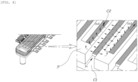
- FIG. 4 is a diagram showing a mechanism of the cooling apparatus for the power module according to the exemplary embodiment of the present disclosure.
- the guide wall S guides the cooling fluid to the inlet and the outlet to flow in the first direction. Since the cooling fluid flows in the first direction while overflowing the pin P having one surface being in contact with the power module E in the process of flowing in the first direction, the primary jet cooling is performed in this process.
- the first channel C1 through which the cooling fluid flows in the first direction is configured to block the outlet side thereof. The blocked and overflowing cooling fluid overflows the plurality of pins P extending in the second direction crossing the first direction and flows into the second channel C2 through the top or bottom of the guide wall S.
- turbulence which is a velocity component in a direction perpendicular to the flow direction, occurs in the process in which the cooling fluid flows into the second channel C2.
- the second channel C2 is configured to block the inlet side, so that the cooling fluid flowing into the second channel C2 flows only to the outlet side.
- the exemplary embodiment of the present disclosure provides an apparatus that uses the cooling fluid in order to cool the power module.
- the exemplary embodiment of the present disclosure intends to apply the effect of the impingement jet cooling.
- the impingement jet cooling means a cooling method capable of locally obtaining the high heat transfer effect as the method for directly spraying cooling air on a high-temperature wall to remove the heat.
- the turbulence means a flow having a velocity component in the direction perpendicular to the flow direction, that is, a flow having irregularity and diffusivity due to vertical and horizontal 3D vorticity other than the flow direction.
- the cooling apparatus for the power module according to the exemplary embodiment of the present disclosure crosses the second direction in which the pin P of the pin plate extends with the first direction in which the cooling fluid flows to the guide wall of the manifold cover M in order to cause the turbulent flow to further increase the effect of this impingement jet cooling.
- This causes the turbulence beyond simply passing the pin plate as the laminar flow like the pock on a golf ball or the bumpy skin of a shark. Therefore, it is possible to improve the cooling performance of the cooling apparatus of the power module according to the exemplary embodiment of the present disclosure.
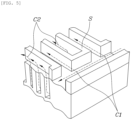
- FIG. 5 is a diagram showing a microchannel of the cooling apparatus for the power module according to the exemplary embodiment of the present disclosure.
- the cooling fluid is introduced from the inlet to form an inlet plenum that is the sum of narrow streams of water.
- the manifold cover M allows the cooling fluid guided based on the guide wall S to flow into the first channel C1 or the second channel C2 to be discharged through the plurality of pins P to form a microchannel.
- the turbulence occurs in the process in which the cooling fluid flowing into the first channel C1 is blocked at the outlet side and flows into the second channel C2 through the pin because the outlet side of the first channel C1 is blocked.
- the cooling fluid that is the turbulence passes through the pin P while flowing to the outlet side of the second channel C2, which is each manifold channel, because the inlet side thereof is blocked. Therefore, the cooling fluid of the second channel C2 with increased vorticity, irregularity, and diffusivity forms the effect of the higher impingement jet cooling.
- a crossing angle at which the second direction and the first direction in which the pin P extends cross each other may be 80 degrees to 100 degrees.
- an angle between the direction in which the pin extends and the flow direction of the cooling fluid of the manifold cover is not necessarily 90 degrees, and another exemplary embodiment such as slightly tilting the direction of the pin may also be implemented.
- FIG. 6 is a diagram showing a thermal analysis simulation result of the cooling apparatus for the power module according to the exemplary embodiment of the present disclosure.
- the cooling fluid flowing from the first channel C1 to the second channel C2 forms vortices around a recirculation zone to cause various shock waves such as oscillating shock, mixing and boundary layer noise, and broad band shock noise. Therefore, even a cooling fluid layer, which could not be cooled in the conventional impingement jet cooling of the laminar flow, is recirculated and involved in the cooling, thereby improving the cooling efficiency.
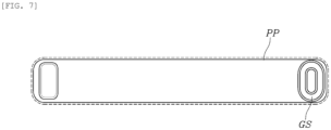
- FIG. 7 is a diagram showing a gasket to which the manifold cover and the pin plate of the cooling apparatus for the power module according to the exemplary embodiment of the present disclosure are coupled
- FIG. 8 is a diagram showing the pin of the cooling apparatus for the power module according to the exemplary embodiment of the present disclosure.
- FIG. 7 is a diagram showing a gasket GS coupled to the pin plate PP of the cooling apparatus for the power module according to the exemplary embodiment of the present disclosure
- the pin plate PP may include a first pin plate coupled to a first surface of the power module E and a second pin plate coupled to a second surface opposite to the first surface of the power module E.
- the pin plate of a first cooling module is in contact with one side surface of the power module
- the pin plate of a second cooling module is in contact with the other side surface of the power module
- the ends of the pin plates of the first and second cooling modules facing each other may be connected to each other through a connection part GS to distribute the cooling fluid.
- the facing pin plates of the first cooling module and the second cooling module may be spaced apart from each other by the thickness of the power module, and the connection part GS may be provided at a point between the separated pin plates.
- the pin plate PP is designed to be in close contact with the power module E to cool both surfaces of the upper and lower surfaces of the power module E. Therefore, as shown in FIG. 7 , the pin plate PP may include the gasket GS having a concave or protruding shape as the connection part GS.
- the manifold cover M of the cooling apparatus for the power module may be coupled to the pin plate PP in any one method among weld joint, adhesive bonding, and bolted joint.
- FIG. 8 is a diagram showing the pin of the cooling apparatus for the power module according to the exemplary embodiment of the present disclosure, and in the cooling apparatus for the power module according to the exemplary embodiment of the present disclosure, a partial or entire shape of the portion where the pin P is formed may be formed so that the size of a first cross section of the pin perpendicular to the direction in which the pin P extends is reduced in the protruding direction.
- a shape of a second cross section of the pin parallel to the direction in which the pin extends may be formed in any one of a right-angled triangle, an isosceles triangle, and a semicircle.
- the pins P may also be alternately formed to be spaced apart from each other at a predetermined interval, and may be repeatedly formed without the predetermined interval.
- the pin P may have a reduced cross-sectional area of the partial region or the entire region in the direction in which the pin extends, and the pin may be a right-angled triangular, isosceles triangular, or semicircular protrusion structure.
- the pin may be a rectangular protrusion structure, but is not limited thereto.
- the cooling apparatus for the power module according to the exemplary embodiment of the present disclosure uses the impingement jet cooling.
- the impingement jet cooling may locally obtain the high heat transfer effect by the method for spraying refrigerant on the local heat-generated surface at high speed to remove the heat. Therefore, it is possible to increase the operation lifespan of the power module.
- the cooling apparatus for the power module according to the exemplary embodiment of the present disclosure effectively implements the impingement jet cooling only by coupling the pin plate to the manifold cover without having to complexly design the channel (flow path) through which the sprayed refrigerant passes in one direction. Therefore, according to the cooling apparatus for the power module according to the exemplary embodiment of the present disclosure, it is possible to simplify the manufacturing process, and to reduce the number of components, thereby reducing the manufacturing cost.
Landscapes
- Engineering & Computer Science (AREA)
- Microelectronics & Electronic Packaging (AREA)
- Physics & Mathematics (AREA)
- Thermal Sciences (AREA)
- Cooling Or The Like Of Semiconductors Or Solid State Devices (AREA)
- Cooling Or The Like Of Electrical Apparatus (AREA)
Abstract
Description
- The present disclosure relates to a cooling apparatus for a power module cooling the power module by using a cooling fluid.
- A power module is applied to an electric vehicle, etc. to control a high voltage and a large current. Therefore, the amount of heat generated is very large and therefore, proper cooling is required to maintain performance and durability. To this end, the power module is cooled through a cooling fluid, or the waste heat of the power module is used to heat a vehicle.
- In the conventional case, it is common to connect a cooling apparatus to one side surface of the power module in order to cool this power module and to distribute the cooling fluid to the cooling apparatus. However, there is a problem in that cooling efficiency is not high by applying a simple tube structure or pin structure generally used to the conventional cooling apparatus.
- Since the cooling efficiency of the electric vehicle, etc. is closely related to the overall energy efficiency of the vehicle and greatly affects the durability or performance maintenance of the power module as well, it is necessary to increase the cooling efficiency of the power module through a new cooling structure.
- The aforementioned background art is technical information possessed by the inventor to derive the exemplary embodiments of the present disclosure or acquired in the derivation process, and is only for enhancing the understanding of the background of the present disclosure. Therefore, the background art should not be taken as being admitted to corresponding to the known art published to the general public prior to the filing of the exemplary embodiments of the present disclosure or the related art already known to those skilled in the art.
- An object of the present disclosure is to provide a cooling apparatus for a power module, which vertically sprays a cooling fluid on a heat-generated surface through a micropin of a pin plate configured in a direction perpendicular to a direction of a manifold cover and cools the heat-generated surface to cause the vertical turbulent flow of the cooling fluid.
- The present disclosure provides a cooling apparatus for a power module including a plurality of cooling modules to contact each of both surfaces of the power module, in which the plurality of cooling modules include a first cooling module and a second cooling module, and at least one of the first and second cooling modules includes: a manifold cover including: a plurality of guide walls extending in a first direction in a state of being spaced apart from each other, and a plurality of cooling channels through the plurality of guide walls, the plurality of cooling channels having a first channel and a second channel, a first end of the first channel is blocked and a second end of the second channel is blocked, the second end of the second channel is opposite the first end of the first channel; and a pin plate having one surface to contact the power module, the pin plate having a plurality of pins extending in a second direction crossing the first direction and disposed on the other surface of the pin plate, and the pin plate is coupled to the manifold cover so that at least one of the plurality of pins faces at least one of the plurality of guide walls, so that cooling fluid to be introduced into the first channel flows in the second direction and then flows out through the second channel.
- The first channel may include a first blocking part connecting first ends of first guide walls on both sides of the first channel so that an outlet side of the first channel is blocked, and the second channel includes a second blocking part connecting second ends of second guide walls on both sides of the second channel so that an inlet side of the second channel is blocked, and the second ends of the second guide walls are opposite the first ends of the first guide walls.
- A crossing angle between the first direction and the second direction may be 80 degrees to 100 degrees.
- The first direction and the second direction may vertically cross each other.
- The first cooling module may contact one surface of the power module and include an inlet through which the cooling fluid is to be introduced through a supply flow path and the second cooling module may contact the other surface of the power module and include an outlet through which the cooling fluid is to flow out through a discharge flow path.
- The inlet may be disposed in the manifold cover of the first cooling module, and the outlet may be disposed in the manifold cover of the second cooling module.
- The pin plate of the first cooling module may contact one side surface of the power module, the pin plate of the second cooling module may contact with the other side surface of the power module, and ends of the pin plates of the first cooling module and the second cooling module facing each other may be connected to each other through a connection part to distribute the cooling fluid.
- The pin plates of the first cooling module and the second cooling module facing each other may be spaced apart from each other by a thickness of the power module, and the connection part may be disposed at a point between the spaced pin plates.
- At least one pin among the plurality of pins of the pin plate may protrude from the pin plate, and the at least one pin may have a shape in which a horizontal cross-sectional area is reduced toward the protruding end.
- The at least one pin may have a shape in which a vertical cross-sectional shape of the protruding end is a triangle or a curve.
- The manifold cover may further include a rim welding, adhered, or bolted to the pin plate.
- A plurality of power modules may be arranged to be spaced apart from each other and between the plurality of cooling modules, so that the plurality of power modules may share the plurality of cooling modules, and the plurality of cooling modules may include a plurality of channel groups to correspond to each of the power module.
- The first channel and the second channel may be present in each of the plurality of channel groups, the first channel may include a first blocking part connecting first ends of first guide walls on both sides of the first channel to block an outlet side thereof, and the second channel may include a second blocking part connecting second ends of second guide walls on both sides of the second channel to block an inlet side thereof, and the second ends of the second guide walls are opposite the first ends of the first guide wall.
- The first channel of an one side channel group may have the first blocking part connected to the second blocking part of the second channel of the other side channel group adjacent thereto, and the second channel of the one side channel group may have the outlet side connected to an inlet side of the first channel of the other side channel group adjacent thereto.
- According to the cooling apparatus for the power module according to the present disclosure, it is possible to vertically spray the cooling fluid on the heat-generated surface through the micropin of the pin plate configured in the direction perpendicular to the direction of the manifold cover and to cool the heat-generated surface to cause the vertical turbulent flow of the cooling fluid, thereby increasing the heat-dissipation performance of the cooling apparatus even without the separate nozzle spray apparatus.
- The effect of the present disclosure is not limited to the aforementioned technical effects, and other technical effects may also be derived from the following description.
- The above and other objects, features and other advantages of the present disclosure will be larger clearly understood from the following detailed description when taken in conjunction with the accompanying drawings, in which:
-
FIG. 1 is a perspective diagram of a cooling apparatus for a power module according to an exemplary embodiment of the present disclosure. -
FIG. 2 is an exploded perspective diagram of the cooling apparatus for the power module shown inFIG. 1 . -
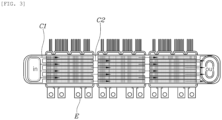
FIG. 3 is a diagram showing a channel of the cooling apparatus for the power module shown inFIG. 1 . -
FIG. 4 is a diagram showing a mechanism of the cooling apparatus for the power module shown inFIG. 1 . -
FIG. 5 is a diagram showing a microchannel of the cooling apparatus for the power module shown inFIG. 1 . -
FIG. 6 is a diagram showing a thermal analysis simulation result of the cooling apparatus for the power module shown inFIG. 1 . -
FIG. 7 is a diagram showing a gasket formed on a pin plate of the cooling apparatus for the power module shown inFIG. 1 . -
FIG. 8 is a diagram showing a pin of a cooling apparatus for a power module according to various exemplary embodiments of the present disclosure. - Specific structural or functional descriptions of the exemplary embodiments of the present disclosure disclosed in the present specification or application are only exemplified for the purpose of describing the exemplary embodiments according to the present disclosure, and the exemplary embodiments according to the present disclosure may be embodied in various forms and should not be interpreted as being limited to the exemplary embodiments described in the present specification or application. Hereinafter, exemplary embodiments of the present disclosure will be described in detail with reference to the accompanying drawings.
-
FIG. 1 is a perspective diagram of a cooling apparatus for a power module according to an exemplary embodiment of the present disclosure, andFIG. 2 is an exploded perspective diagram of the cooling apparatus for the power module shown inFIG. 1 . Therefore, a cooling apparatus for a power module according to an exemplary embodiment of the present disclosure includes a power module E and a plurality of cooling modules provided to be in contact with each of both surfaces of the power module in order to cool the power module. Each cooling module is provided with a manifold cover M provided with a plurality of guide walls S extending in a first direction to partition a cooling channel into a plurality of cooling channels so that a cooling fluid flows from an inlet to an outlet in the first direction. In addition, the plurality of cooling channels partitioned by the guide wall S are composed of a first channel C1 whose outlet side is blocked and a second channel C2 whose inlet side is blocked. - In addition, the cooling module according to the present disclosure is provided with a pin plate PP. The pin plate PP has one surface being in contact with the power module E and has a plurality of pins (P) extending in a second direction formed on the other surface thereof so that the cooling fluid introduced from the inlet to the first channel C1 flows in the second direction crossing the first direction and then flows to the outlet through the second channel C2. In other words, the cooling fluid is designed to be partitioned into a plurality of cooling fluids, guided in the first direction, and then blocked to flow in the second direction in which the pin P extends to form an impingement jet cooling structure, thereby increasing the efficiency of heat exchange.
- First, as shown in
FIG. 1 , the cooling apparatus for the power module according to an exemplary embodiment of the present disclosure is designed based on double-sided cooling that simultaneously cools all of both surfaces of the power module E. Therefore, as shown inFIGS. 1 and2 , the cooling apparatus for the power module may be configured in a series-type structure in which the cooling fluid introduced from an inlet I flows and flows out to an outlet O. AlthoughFIG. 1 shows a direction in which the cooling fluid flows from the top to the bottom, the flow direction may also be opposite thereto and is not limited to only the vertical direction. - As shown in
FIG. 2 , the pin plate PP has one surface of a plate B being in contact with the power module E and has the plurality of pins P formed on the other surface thereof. The manifold cover M includes the first channel C1 whose outlet side is blocked and the second channel C2 whose inlet side is blocked. The power module E is cooled by forming the cooling module including the manifold cover M and the pin plate PP to be in contact with each of both surfaces of the power module E. - In the cooling apparatus for the power module according to the exemplary embodiment of the present disclosure, the first channel C1 may include a first blocking part B1 formed to protrude from the end from which the guide wall extends in order to block the outlet side thereof in the manifold cover M, and the second channel C2 may include a second blocking part B2 formed to protrude from the end from which the guide wall extends in order to block the inlet side thereof in the manifold cover M.
- In other words, the first blocking part B1 and the second blocking part B2 may be configured so that the cooling fluid introduced from the inlet flows and the outlet side of the first channel C1 is blocked, or the inlet side of the second channel C2 is blocked and the cooling fluid flows to the outlet side of the second channel C2, respectively.
FIG. 2 shows each of the first blocking part B1 and the second blocking part B2 in a protruding form, but the present disclosure is not limited thereto. In addition, as shown inFIG. 2 , the cooling apparatus for the power module according to the exemplary embodiment of the present disclosure is provided to be in contact with each of both surfaces of the power module E, thereby increasing cooling performance. - Specifically, the pin plate PP shown in
FIG. 2 includes the pins P alternately formed at a separated interval to extend in the second direction. In other words, the pin P shown inFIG. 1 has the form of a fin pin configured like a fin.FIG. 2 shows that the pin P is formed in a direction perpendicular to the plate B, but the present disclosure is not limited thereto. - Meanwhile, as shown in
FIG. 3 , a cooling apparatus for a power module according to another exemplary embodiment of the present disclosure includes: a plurality of power modules E and a plurality of cooling modules provided to be in contact with each of both surfaces of the power module E in order to cool each power module E, in which the cooling module and the other cooling modules adjacent thereto are connected in series with each other. - Therefore, the cooling fluid flowing to the outlet through the second channel C2 flows into the first channels C1 of the manifold covers M of the other neighboring cooling modules connected in series. In other words, the cooling module cools the other neighboring power modules. In addition, the cooling apparatus for the power module according to another exemplary embodiment of the present disclosure allows the cooling fluid to cool the power module at a greater mass flow rate than in the method for cooling each power module in parallel.
- Specifically, the plurality of power modules E are arranged to be spaced apart from each other between a pair of cooling modules, so that the plurality of power modules E may share the cooling module, and the cooling module may be formed with a plurality of channel group G to correspond to each power module E.
- Each channel group G is provided with the first channel C1 and the second channel C2, in which the first channel (C1) is formed with the first blocking part B1 connecting one ends of the guide walls of both sides partitioning the first channel C1 in order to block the outlet side thereof, and the second channel C2 is formed with the second blocking part B2 connecting the other ends of the guide walls of both sides partitioning the second channel C2 to block the inlet side thereof.
- The first blocking part of the first channel of an one side channel group is connected to the second blocking part of the second channel of the other side channel group adjacent thereto, and the second channel of the one side channel group has the outlet side connected to the inlet side of the first channel of the other side channel group adjacent thereto, so that the cooling fluid repeatedly moves in the order of the first channel-the second channel-the first channel and implements the impingement jet cooling.
- In addition, as shown in
FIG. 3 , the second direction in which the pin P extends may be perpendicular to the direction in which the guide wall S extends. In other words, the first channel included in the manifold cover M allows the cooling fluid to go through the vertical pin while flowing in the direction in which the guide wall S extends so that the effect of the impingement jet cooling may be implemented. -
FIG. 4 is a diagram showing a mechanism of the cooling apparatus for the power module according to the exemplary embodiment of the present disclosure. As shown inFIG. 4 , the guide wall S guides the cooling fluid to the inlet and the outlet to flow in the first direction. Since the cooling fluid flows in the first direction while overflowing the pin P having one surface being in contact with the power module E in the process of flowing in the first direction, the primary jet cooling is performed in this process. Next, the first channel C1 through which the cooling fluid flows in the first direction is configured to block the outlet side thereof. The blocked and overflowing cooling fluid overflows the plurality of pins P extending in the second direction crossing the first direction and flows into the second channel C2 through the top or bottom of the guide wall S. Therefore, in the cooling apparatus for the power module according to the exemplary embodiment of the present disclosure, turbulence, which is a velocity component in a direction perpendicular to the flow direction, occurs in the process in which the cooling fluid flows into the second channel C2. Thereafter, the second channel C2 is configured to block the inlet side, so that the cooling fluid flowing into the second channel C2 flows only to the outlet side. - The exemplary embodiment of the present disclosure provides an apparatus that uses the cooling fluid in order to cool the power module. In order to cool this power module, the exemplary embodiment of the present disclosure intends to apply the effect of the impingement jet cooling. Here, the impingement jet cooling means a cooling method capable of locally obtaining the high heat transfer effect as the method for directly spraying cooling air on a high-temperature wall to remove the heat. In order to actively implement the effect of the jet cooling method, it is necessary to use turbulent flow other than laminar flow. Here, the turbulence means a flow having a velocity component in the direction perpendicular to the flow direction, that is, a flow having irregularity and diffusivity due to vertical and horizontal 3D vorticity other than the flow direction. When the turbulence occurs around the object, the cooling area and the mixing of the cooling fluid may become larger, thereby increasing the cooling efficiency.
- The cooling apparatus for the power module according to the exemplary embodiment of the present disclosure crosses the second direction in which the pin P of the pin plate extends with the first direction in which the cooling fluid flows to the guide wall of the manifold cover M in order to cause the turbulent flow to further increase the effect of this impingement jet cooling. This causes the turbulence beyond simply passing the pin plate as the laminar flow like the pock on a golf ball or the bumpy skin of a shark. Therefore, it is possible to improve the cooling performance of the cooling apparatus of the power module according to the exemplary embodiment of the present disclosure.
-
FIG. 5 is a diagram showing a microchannel of the cooling apparatus for the power module according to the exemplary embodiment of the present disclosure. As shown inFIG. 5 , the cooling fluid is introduced from the inlet to form an inlet plenum that is the sum of narrow streams of water. The manifold cover M allows the cooling fluid guided based on the guide wall S to flow into the first channel C1 or the second channel C2 to be discharged through the plurality of pins P to form a microchannel. As the second direction in which the pin P extends and the first direction of the guide wall S of the manifold cover M cross each other, the turbulence occurs in the process in which the cooling fluid flowing into the first channel C1 is blocked at the outlet side and flows into the second channel C2 through the pin because the outlet side of the first channel C1 is blocked. The cooling fluid that is the turbulence passes through the pin P while flowing to the outlet side of the second channel C2, which is each manifold channel, because the inlet side thereof is blocked. Therefore, the cooling fluid of the second channel C2 with increased vorticity, irregularity, and diffusivity forms the effect of the higher impingement jet cooling. - Unlike shown in
FIG. 5 , in the cooling apparatus for the power module according to the exemplary embodiment of the present disclosure, a crossing angle at which the second direction and the first direction in which the pin P extends cross each other may be 80 degrees to 100 degrees. In other words, an angle between the direction in which the pin extends and the flow direction of the cooling fluid of the manifold cover is not necessarily 90 degrees, and another exemplary embodiment such as slightly tilting the direction of the pin may also be implemented. -
FIG. 6 is a diagram showing a thermal analysis simulation result of the cooling apparatus for the power module according to the exemplary embodiment of the present disclosure. The cooling fluid flowing from the first channel C1 to the second channel C2 forms vortices around a recirculation zone to cause various shock waves such as oscillating shock, mixing and boundary layer noise, and broad band shock noise. Therefore, even a cooling fluid layer, which could not be cooled in the conventional impingement jet cooling of the laminar flow, is recirculated and involved in the cooling, thereby improving the cooling efficiency. -
FIG. 7 is a diagram showing a gasket to which the manifold cover and the pin plate of the cooling apparatus for the power module according to the exemplary embodiment of the present disclosure are coupled, andFIG. 8 is a diagram showing the pin of the cooling apparatus for the power module according to the exemplary embodiment of the present disclosure. - Specifically,
FIG. 7 is a diagram showing a gasket GS coupled to the pin plate PP of the cooling apparatus for the power module according to the exemplary embodiment of the present disclosure, and the pin plate PP may include a first pin plate coupled to a first surface of the power module E and a second pin plate coupled to a second surface opposite to the first surface of the power module E. - The pin plate of a first cooling module is in contact with one side surface of the power module, the pin plate of a second cooling module is in contact with the other side surface of the power module, and the ends of the pin plates of the first and second cooling modules facing each other may be connected to each other through a connection part GS to distribute the cooling fluid. In addition, the facing pin plates of the first cooling module and the second cooling module may be spaced apart from each other by the thickness of the power module, and the connection part GS may be provided at a point between the separated pin plates.
- In other words, the pin plate PP is designed to be in close contact with the power module E to cool both surfaces of the upper and lower surfaces of the power module E. Therefore, as shown in
FIG. 7 , the pin plate PP may include the gasket GS having a concave or protruding shape as the connection part GS. - In addition, as a region shown by the dotted line in
FIG. 7 , the manifold cover M of the cooling apparatus for the power module according to the exemplary embodiment of the present disclosure may be coupled to the pin plate PP in any one method among weld joint, adhesive bonding, and bolted joint. -
FIG. 8 is a diagram showing the pin of the cooling apparatus for the power module according to the exemplary embodiment of the present disclosure, and in the cooling apparatus for the power module according to the exemplary embodiment of the present disclosure, a partial or entire shape of the portion where the pin P is formed may be formed so that the size of a first cross section of the pin perpendicular to the direction in which the pin P extends is reduced in the protruding direction. In addition, in the cooling apparatus for the power module according to the exemplary embodiment of the present disclosure, for the shape of a portion or the entire portion where the pin P is formed, a shape of a second cross section of the pin parallel to the direction in which the pin extends may be formed in any one of a right-angled triangle, an isosceles triangle, and a semicircle. - As in the exemplary embodiment shown in
FIG. 8 , the pins P may also be alternately formed to be spaced apart from each other at a predetermined interval, and may be repeatedly formed without the predetermined interval. As in another exemplary embodiment shown inFIG. 8 , the pin P may have a reduced cross-sectional area of the partial region or the entire region in the direction in which the pin extends, and the pin may be a right-angled triangular, isosceles triangular, or semicircular protrusion structure. Of course, as shown inFIG. 4 , the pin may be a rectangular protrusion structure, but is not limited thereto. - The cooling apparatus for the power module according to the exemplary embodiment of the present disclosure uses the impingement jet cooling. The impingement jet cooling may locally obtain the high heat transfer effect by the method for spraying refrigerant on the local heat-generated surface at high speed to remove the heat. Therefore, it is possible to increase the operation lifespan of the power module. In addition, the cooling apparatus for the power module according to the exemplary embodiment of the present disclosure effectively implements the impingement jet cooling only by coupling the pin plate to the manifold cover without having to complexly design the channel (flow path) through which the sprayed refrigerant passes in one direction. Therefore, according to the cooling apparatus for the power module according to the exemplary embodiment of the present disclosure, it is possible to simplify the manufacturing process, and to reduce the number of components, thereby reducing the manufacturing cost.
- While the specific exemplary embodiments of the disclosure have been shown and described, it will be apparent to those skilled in the art that the present disclosure may be variously improved and changed without departing from the technical spirit of the present disclosure provided by the appended claims.
- The invention may be understood with reference to the following items:
- 1. A cooling apparatus for a power module comprising a plurality of cooling modules to contact each of both surfaces of the power module,
- wherein the plurality of cooling modules include a first cooling module and a second cooling module, and at least one of the first and second cooling modules comprises
- a manifold cover including:
- a plurality of guide walls extending in a first direction in a state of being spaced apart from each other, and
- a plurality of cooling channels through the plurality of guide walls, the plurality of cooling channels having a first channel and a second channel, a first end of the first channel is blocked and a second end of the second channel is blocked, the second end of the second channel being opposite the first end of the first channel; and
- a pin plate having one surface to contact the power module, the pin plate having a plurality of pins extending in a second direction crossing the first direction and disposed on the other surface of the pin plate, and the pin plate is coupled to the manifold cover so that at least one of the plurality of pins faces at least one of the plurality of guide walls, so that a cooling fluid to be introduced into the first channel flows in the second direction and then flows out through the second channel.
- 2. The cooling apparatus for the power module of item 1,
wherein the first channel includes a first blocking part connecting first ends of first guide walls on both sides of the first channel to block an outlet side thereof, and the second channel includes a second blocking part connecting second ends of second guide walls on both sides of the second channel to block an inlet side thereof, and the second ends of the second guide walls are opposite the first ends of the first guide walls. - 3. The cooling apparatus for the power module of item 1 or 2,
wherein a crossing angle between the first direction and the second direction is 80 degrees to 100 degrees. - 4. The cooling apparatus for the power module of any one of preceding items,
wherein the first direction and the second direction vertically cross each other. - 5. The cooling apparatus for the power module of any one of the preceding items,
wherein- the first cooling module is to contact one surface of the power module and comprises an inlet through which the cooling fluid is to be introduced through a supply flow path and
- the second cooling module is to contact the other surface of the power module and comprises an outlet through which the cooling fluid is to flow out through a discharge flow path.
- 6. The cooling apparatus for the power module of item 5,
wherein the inlet is disposed in the manifold cover of the first cooling module, and the outlet is disposed in the manifold cover of the second cooling module. - 7. The cooling apparatus for the power module of item 5 or 6,
wherein the pin plate of the first cooling module is to contact one side surface of the power module, the pin plate of the second cooling module is to contact with the other side surface of the power module, and ends of the pin plates of the first cooling module and the second cooling module facing each other are connected to each other through a connection part to distribute the cooling fluid. - 8. The cooling apparatus for the power module of item 7,
wherein the pin plates of the first cooling module and the second cooling module facing each other are spaced apart from each other by a thickness of the power module, and the connection part is disposed at a point between the spaced pin plates. - 9. The cooling apparatus for the power module of any one of the preceding items,
wherein at least one pin among the plurality of pins of the pin plate protrudes from the pin plate, and the at least one pin has a shape in which a horizontal cross-sectional area is reduced toward the protruding end. - 10. The cooling apparatus for the power module of item 9,
wherein the at least one pin has a shape in which a vertical cross-sectional shape of the protruding end is a triangle or a curve. - 11. The cooling apparatus for the power module of any one of the preceding items,
wherein the manifold cover further includes a rim welded, adhered, or bolted to the pin plate. - 12. The cooling apparatus for the power module of any one of the preceding items,
wherein a plurality of power modules are to be arranged to be spaced apart from each other and between the plurality of cooling modules, so that the plurality of power modules share the plurality of cooling modules, and the plurality of cooling modules further includes a plurality of channel groups to correspond to each of the power module. - 13. The cooling apparatus for the power module of item 12,
wherein the first channel and the second channel are present in each of the plurality of channel groups, the first channel includes a first blocking part connecting first ends of first guide walls on both sides of the first channel to block an outlet side thereof, and the second channel includes a second blocking part connecting second ends of second guide walls on both sides of the second channel to block an inlet side thereof, and the second ends of the second guide walls are opposite the first ends of the first guide walls. - 14. The cooling apparatus for the power module of item 13,
wherein the first channel of an one side channel group has the first blocking part connected to the second blocking part of the second channel of the other side channel group adjacent thereto, and the second channel of the one side channel group has the outlet side connected to an inlet side of the first channel of the other side channel group adjacent thereto.
Claims (14)
- A cooling apparatus for a power module comprising a plurality of cooling modules to contact each of both surfaces of the power module,wherein the plurality of cooling modules include a first cooling module and a second cooling module, and at least one of the first and second cooling modules comprisesa manifold cover including:a plurality of guide walls extending in a first direction in a state of being spaced apart from each other, anda plurality of cooling channels through the plurality of guide walls, the plurality of cooling channels having a first channel and a second channel, a first end of the first channel is blocked and a second end of the second channel is blocked, the second end of the second channel being opposite the first end of the first channel; anda pin plate having one surface to contact the power module, the pin plate having a plurality of pins extending in a second direction crossing the first direction and disposed on the other surface of the pin plate, and the pin plate is coupled to the manifold cover so that at least one of the plurality of pins faces at least one of the plurality of guide walls, so that a cooling fluid to be introduced into the first channel flows in the second direction and then flows out through the second channel.
- The cooling apparatus for the power module of claim 1,
wherein the first channel includes a first blocking part connecting first ends of first guide walls on both sides of the first channel to block an outlet side thereof, and the second channel includes a second blocking part connecting second ends of second guide walls on both sides of the second channel to block an inlet side thereof, and the second ends of the second guide walls are opposite the first ends of the first guide walls. - The cooling apparatus for the power module of claim 1,
wherein a crossing angle between the first direction and the second direction is 80 degrees to 100 degrees. - The cooling apparatus for the power module of claim 1,
wherein the first direction and the second direction vertically cross each other. - The cooling apparatus for the power module of claim 1,
whereinthe first cooling module is to contact one surface of the power module and comprises an inlet through which the cooling fluid is to be introduced through a supply flow path andthe second cooling module is to contact the other surface of the power module and comprises an outlet through which the cooling fluid is to flow out through a discharge flow path. - The cooling apparatus for the power module of claim 5,
wherein the inlet is disposed in the manifold cover of the first cooling module, and the outlet is disposed in the manifold cover of the second cooling module. - The cooling apparatus for the power module of claim 5,
wherein the pin plate of the first cooling module is to contact one side surface of the power module, the pin plate of the second cooling module is to contact with the other side surface of the power module, and ends of the pin plates of the first cooling module and the second cooling module facing each other are connected to each other through a connection part to distribute the cooling fluid. - The cooling apparatus for the power module of claim 7,
wherein the pin plates of the first cooling module and the second cooling module facing each other are spaced apart from each other by a thickness of the power module, and the connection part is disposed at a point between the spaced pin plates. - The cooling apparatus for the power module of claim 1,
wherein at least one pin among the plurality of pins of the pin plate protrudes from the pin plate, and the at least one pin has a shape in which a horizontal cross-sectional area is reduced toward the protruding end. - The cooling apparatus for the power module of claim 9,
wherein the at least one pin has a shape in which a vertical cross-sectional shape of the protruding end is a triangle or a curve. - The cooling apparatus for the power module of claim 1,
wherein the manifold cover further includes a rim welded, adhered, or bolted to the pin plate. - The cooling apparatus for the power module of claim 1,
wherein a plurality of power modules are to be arranged to be spaced apart from each other and between the plurality of cooling modules, so that the plurality of power modules share the plurality of cooling modules, and the plurality of cooling modules further includes a plurality of channel groups to correspond to each of the power module. - The cooling apparatus for the power module of claim 12,
wherein the first channel and the second channel are present in each of the plurality of channel groups, the first channel includes a first blocking part connecting first ends of first guide walls on both sides of the first channel to block an outlet side thereof, and the second channel includes a second blocking part connecting second ends of second guide walls on both sides of the second channel to block an inlet side thereof, and the second ends of the second guide walls are opposite the first ends of the first guide walls. - The cooling apparatus for the power module of claim 13,
wherein the first channel of an one side channel group has the first blocking part connected to the second blocking part of the second channel of the other side channel group adjacent thereto, and the second channel of the one side channel group has the outlet side connected to an inlet side of the first channel of the other side channel group adjacent thereto.
Applications Claiming Priority (1)
| Application Number | Priority Date | Filing Date | Title |
|---|---|---|---|
| KR1020210183141A KR102952381B1 (en) | 2021-12-20 | 2021-12-20 | Cooling apparatus for power module |
Publications (1)
| Publication Number | Publication Date |
|---|---|
| EP4199674A1 true EP4199674A1 (en) | 2023-06-21 |
Family
ID=84360372
Family Applications (1)
| Application Number | Title | Priority Date | Filing Date |
|---|---|---|---|
| EP22208313.1A Pending EP4199674A1 (en) | 2021-12-20 | 2022-11-18 | Cooling apparatus for power module |
Country Status (4)
| Country | Link |
|---|---|
| US (2) | US12150273B2 (en) |
| EP (1) | EP4199674A1 (en) |
| KR (1) | KR102952381B1 (en) |
| CN (1) | CN116321922A (en) |
Families Citing this family (8)
| Publication number | Priority date | Publication date | Assignee | Title |
|---|---|---|---|---|
| CN115943554A (en) * | 2020-08-18 | 2023-04-07 | 日立安斯泰莫株式会社 | Power conversion device, method of manufacturing power conversion device |
| KR20230090747A (en) | 2021-12-15 | 2023-06-22 | 현대자동차주식회사 | Cooling apparatus for both sides of power module |
| KR20230158286A (en) * | 2022-05-11 | 2023-11-20 | 현대자동차주식회사 | Cooling apparatus for power module |
| KR20230169642A (en) | 2022-06-09 | 2023-12-18 | 현대자동차주식회사 | Cooling apparatus for power module |
| US12122251B2 (en) * | 2022-09-28 | 2024-10-22 | BorgWarner US Technologies LLC | Systems and methods for bidirectional message architecture for inverter for electric vehicle |
| DE102022128698A1 (en) * | 2022-10-28 | 2024-05-08 | Erwin Quarder Systemtechnik Gmbh | Cooling device |
| US12484187B2 (en) | 2023-06-28 | 2025-11-25 | Hyundai Motor Company | Cooling apparatus for power module |
| DE102023213051A1 (en) * | 2023-12-20 | 2025-06-26 | Zf Friedrichshafen Ag | Assembly with power module and cooler, inverter and motor vehicle |
Citations (5)
| Publication number | Priority date | Publication date | Assignee | Title |
|---|---|---|---|---|
| US20140252585A1 (en) * | 2013-03-08 | 2014-09-11 | Taiwan Semiconductor Manufacturing Company, Ltd. | Packages for Semiconductor Devices, Packaged Semiconductor Devices, and Methods of Cooling Packaged Semiconductor Devices |
| US20170055378A1 (en) * | 2015-08-20 | 2017-02-23 | Toyota Motor Engineering & Manufacturing North America, Inc. | Configurable double-sided modular jet impingement assemblies for electronics cooling |
| US20190181717A1 (en) * | 2017-12-08 | 2019-06-13 | Toyota Motor Engineering & Manufacturing North America, Inc. | Cooling system for vehicle motor drive |
| US20200344920A1 (en) * | 2019-04-24 | 2020-10-29 | Hyundai Motor Company | Cooling system for power conversion device |
| EP4203637A1 (en) * | 2021-12-15 | 2023-06-28 | Hyundai Motor Company | Double-sided cooling apparatus for power module |
Family Cites Families (27)
| Publication number | Priority date | Publication date | Assignee | Title |
|---|---|---|---|---|
| CA2329408C (en) | 2000-12-21 | 2007-12-04 | Long Manufacturing Ltd. | Finned plate heat exchanger |
| US7836597B2 (en) | 2002-11-01 | 2010-11-23 | Cooligy Inc. | Method of fabricating high surface to volume ratio structures and their integration in microheat exchangers for liquid cooling system |
| DK200301577A (en) * | 2003-10-27 | 2005-04-28 | Danfoss Silicon Power Gmbh | Flow distribution unit and cooling unit |
| US7836940B2 (en) | 2005-06-29 | 2010-11-23 | Microvection, Inc. | Microchannel cooling device for small heat sources |
| WO2011083578A1 (en) * | 2010-01-08 | 2011-07-14 | トヨタ自動車株式会社 | Semiconductor module |
| JP5589468B2 (en) * | 2010-03-17 | 2014-09-17 | 日産自動車株式会社 | Heating element cooling device |
| JP5523542B1 (en) * | 2012-12-07 | 2014-06-18 | 三菱電機株式会社 | Cooling system |
| US9449895B2 (en) * | 2013-05-03 | 2016-09-20 | Infineon Technologies Ag | Cooling system for molded modules and corresponding manufacturing methods |
| US9247679B2 (en) | 2013-05-24 | 2016-01-26 | Toyota Motor Engineering & Manufacturing North America, Inc. | Jet impingement coolers and power electronics modules comprising the same |
| US9437523B2 (en) * | 2014-05-30 | 2016-09-06 | Toyota Motor Engineering & Manufacturing North America, Inc. | Two-sided jet impingement assemblies and power electronics modules comprising the same |
| US9445526B2 (en) | 2014-12-22 | 2016-09-13 | Toyota Motor Engineering & Manufacturing North America, Inc. | Modular jet impingement assemblies with passive and active flow control for electronics cooling |
| WO2016144888A1 (en) | 2015-03-09 | 2016-09-15 | J R Thermal LLC | Compact stacked fin heat exchanger |
| US9538691B2 (en) * | 2015-04-15 | 2017-01-03 | Ford Global Technologies, Llc | Power inverter for a vehicle |
| US10475724B2 (en) * | 2015-08-27 | 2019-11-12 | Dana Canada Corporation | Heat exchangers for dual-sided cooling |
| CN205940237U (en) | 2016-06-28 | 2017-02-08 | 陈祖卫 | Indirect evaporation cooling heat exchanger of diaphragm formula dew point |
| US9955613B2 (en) * | 2016-09-13 | 2018-04-24 | Denso International America, Inc. | Cooler and power electronic module having the same |
| KR102030143B1 (en) * | 2017-09-18 | 2019-10-08 | 현대자동차(주) | Double side water cooler |
| WO2020013348A1 (en) * | 2018-07-09 | 2020-01-16 | 엘지전자 주식회사 | Cooling apparatus |
| KR102429990B1 (en) | 2018-10-17 | 2022-08-05 | 현대모비스 주식회사 | Power semiconductor use device |
| US20200375069A1 (en) * | 2019-04-22 | 2020-11-26 | Yoatian Zhang | High pressure heat dissipation apparatus for power semiconductor devices |
| CN110425914B (en) | 2019-06-28 | 2021-02-09 | 中国空间技术研究院 | A low-resistance enhanced heat transfer structure based on nanometer superwetted interface |
| US11350545B2 (en) * | 2019-12-05 | 2022-05-31 | Ge Aviation Systems Llc | Cold plate assembly for an electronic component |
| KR20210097489A (en) * | 2020-01-30 | 2021-08-09 | 엘지전자 주식회사 | Power module assembly |
| US11149937B2 (en) * | 2020-01-30 | 2021-10-19 | Toyota Motor Engineering & Manufacturing North America, Inc. | Functionally graded manifold microchannel heat sinks |
| KR20210132999A (en) * | 2020-04-28 | 2021-11-05 | 엘지전자 주식회사 | Power module assembly |
| US11849569B2 (en) * | 2020-10-30 | 2023-12-19 | Toyota Motor Engineering & Manufacturing North America, Inc. | Ultra-compact configurable double-sided manifold micro-channel cold plate |
| US11596088B2 (en) * | 2021-01-29 | 2023-02-28 | Toyota Motor Engineering & Manufacturing North America, Inc. | Asymmetric configurable double-sided manifold micro-channel cold plates |
-
2021
- 2021-12-20 KR KR1020210183141A patent/KR102952381B1/en active Active
-
2022
- 2022-11-04 US US17/980,889 patent/US12150273B2/en active Active
- 2022-11-18 EP EP22208313.1A patent/EP4199674A1/en active Pending
- 2022-11-25 CN CN202211491208.9A patent/CN116321922A/en active Pending
-
2024
- 2024-10-22 US US18/923,003 patent/US20250048589A1/en active Pending
Patent Citations (5)
| Publication number | Priority date | Publication date | Assignee | Title |
|---|---|---|---|---|
| US20140252585A1 (en) * | 2013-03-08 | 2014-09-11 | Taiwan Semiconductor Manufacturing Company, Ltd. | Packages for Semiconductor Devices, Packaged Semiconductor Devices, and Methods of Cooling Packaged Semiconductor Devices |
| US20170055378A1 (en) * | 2015-08-20 | 2017-02-23 | Toyota Motor Engineering & Manufacturing North America, Inc. | Configurable double-sided modular jet impingement assemblies for electronics cooling |
| US20190181717A1 (en) * | 2017-12-08 | 2019-06-13 | Toyota Motor Engineering & Manufacturing North America, Inc. | Cooling system for vehicle motor drive |
| US20200344920A1 (en) * | 2019-04-24 | 2020-10-29 | Hyundai Motor Company | Cooling system for power conversion device |
| EP4203637A1 (en) * | 2021-12-15 | 2023-06-28 | Hyundai Motor Company | Double-sided cooling apparatus for power module |
Also Published As
| Publication number | Publication date |
|---|---|
| US12150273B2 (en) | 2024-11-19 |
| CN116321922A (en) | 2023-06-23 |
| US20230200008A1 (en) | 2023-06-22 |
| KR102952381B1 (en) | 2026-04-13 |
| US20250048589A1 (en) | 2025-02-06 |
| KR20230094013A (en) | 2023-06-27 |
Similar Documents
| Publication | Publication Date | Title |
|---|---|---|
| US12150273B2 (en) | Cooling apparatus for power module | |
| KR20230158286A (en) | Cooling apparatus for power module | |
| US12402286B2 (en) | Double-sided cooling apparatus for power module | |
| CN116190330B (en) | Manifold microchannel heat sink based on hot spot area directional optimization | |
| US8490419B2 (en) | Interlocked jets cooling method and apparatus | |
| US9657999B2 (en) | Alternating channel heat exchanger | |
| US10422592B2 (en) | Double-sided cooler | |
| KR20230169642A (en) | Cooling apparatus for power module | |
| US7458416B2 (en) | Heat-exchanging device | |
| JP4041437B2 (en) | Semiconductor device cooling device | |
| US20240431071A1 (en) | Power module cooling device | |
| CN114245583A (en) | Flow channel structure for chip cooling and manufacturing method thereof | |
| JP2008016872A (en) | Semiconductor device cooling device | |
| US20250107038A1 (en) | Jet impingement cooling systems and related methods of cooling high heat flux devices | |
| CN118156236A (en) | Jet impingement cooling device | |
| US20200240724A1 (en) | Heat Exchanger Device | |
| CN112788918B (en) | Porous medium turbulent flow jet cooling device | |
| CN113490394A (en) | Vein bionic microchannel coupling jet flow heat exchange system | |
| CN108598053A (en) | A kind of efficient microchannel jet stream is heat sink | |
| CN116847628B (en) | A jet microchannel heat sink | |
| CN218731270U (en) | Liquid cooling board and battery package tray | |
| KR102704167B1 (en) | Manifold mini-channel heat sink | |
| JP2019079908A (en) | Cooling device and semiconductor module including the same | |
| US10168112B2 (en) | Heat exchanging apparatus and method for transferring heat | |
| CN222674796U (en) | Water cooling plate device with jet flow and micro-flow channel |
Legal Events
| Date | Code | Title | Description |
|---|---|---|---|
| PUAI | Public reference made under article 153(3) epc to a published international application that has entered the european phase |
Free format text: ORIGINAL CODE: 0009012 |
|
| STAA | Information on the status of an ep patent application or granted ep patent |
Free format text: STATUS: THE APPLICATION HAS BEEN PUBLISHED |
|
| AK | Designated contracting states |
Kind code of ref document: A1 Designated state(s): AL AT BE BG CH CY CZ DE DK EE ES FI FR GB GR HR HU IE IS IT LI LT LU LV MC ME MK MT NL NO PL PT RO RS SE SI SK SM TR |
|
| STAA | Information on the status of an ep patent application or granted ep patent |
Free format text: STATUS: REQUEST FOR EXAMINATION WAS MADE |
|
| 17P | Request for examination filed |
Effective date: 20231219 |
|
| RBV | Designated contracting states (corrected) |
Designated state(s): AL AT BE BG CH CY CZ DE DK EE ES FI FR GB GR HR HU IE IS IT LI LT LU LV MC ME MK MT NL NO PL PT RO RS SE SI SK SM TR |
|
| P01 | Opt-out of the competence of the unified patent court (upc) registered |
Free format text: CASE NUMBER: APP_13480/2025 Effective date: 20250319 |
|
| STAA | Information on the status of an ep patent application or granted ep patent |
Free format text: STATUS: EXAMINATION IS IN PROGRESS |
|
| 17Q | First examination report despatched |
Effective date: 20251219 |