EP4199208B1 - Batteriepack - Google Patents
Batteriepack Download PDFInfo
- Publication number
- EP4199208B1 EP4199208B1 EP21894917.0A EP21894917A EP4199208B1 EP 4199208 B1 EP4199208 B1 EP 4199208B1 EP 21894917 A EP21894917 A EP 21894917A EP 4199208 B1 EP4199208 B1 EP 4199208B1
- Authority
- EP
- European Patent Office
- Prior art keywords
- battery
- mounting
- plate
- hole
- pack
- Prior art date
- Legal status (The legal status is an assumption and is not a legal conclusion. Google has not performed a legal analysis and makes no representation as to the accuracy of the status listed.)
- Active
Links
Images


Classifications
-
- H—ELECTRICITY
- H01—ELECTRIC ELEMENTS
- H01M—PROCESSES OR MEANS, e.g. BATTERIES, FOR THE DIRECT CONVERSION OF CHEMICAL ENERGY INTO ELECTRICAL ENERGY
- H01M50/00—Constructional details or processes of manufacture of the non-active parts of electrochemical cells other than fuel cells, e.g. hybrid cells
- H01M50/20—Mountings; Secondary casings or frames; Racks, modules or packs; Suspension devices; Shock absorbers; Transport or carrying devices; Holders
- H01M50/204—Racks, modules or packs for multiple batteries or multiple cells
- H01M50/207—Racks, modules or packs for multiple batteries or multiple cells characterised by their shape
- H01M50/209—Racks, modules or packs for multiple batteries or multiple cells characterised by their shape adapted for prismatic or rectangular cells
-
- H—ELECTRICITY
- H01—ELECTRIC ELEMENTS
- H01M—PROCESSES OR MEANS, e.g. BATTERIES, FOR THE DIRECT CONVERSION OF CHEMICAL ENERGY INTO ELECTRICAL ENERGY
- H01M50/00—Constructional details or processes of manufacture of the non-active parts of electrochemical cells other than fuel cells, e.g. hybrid cells
- H01M50/20—Mountings; Secondary casings or frames; Racks, modules or packs; Suspension devices; Shock absorbers; Transport or carrying devices; Holders
- H01M50/204—Racks, modules or packs for multiple batteries or multiple cells
- H01M50/207—Racks, modules or packs for multiple batteries or multiple cells characterised by their shape
- H01M50/211—Racks, modules or packs for multiple batteries or multiple cells characterised by their shape adapted for pouch cells
-
- H—ELECTRICITY
- H01—ELECTRIC ELEMENTS
- H01M—PROCESSES OR MEANS, e.g. BATTERIES, FOR THE DIRECT CONVERSION OF CHEMICAL ENERGY INTO ELECTRICAL ENERGY
- H01M50/00—Constructional details or processes of manufacture of the non-active parts of electrochemical cells other than fuel cells, e.g. hybrid cells
- H01M50/20—Mountings; Secondary casings or frames; Racks, modules or packs; Suspension devices; Shock absorbers; Transport or carrying devices; Holders
- H01M50/218—Mountings; Secondary casings or frames; Racks, modules or packs; Suspension devices; Shock absorbers; Transport or carrying devices; Holders characterised by the material
- H01M50/22—Mountings; Secondary casings or frames; Racks, modules or packs; Suspension devices; Shock absorbers; Transport or carrying devices; Holders characterised by the material of the casings or racks
- H01M50/222—Inorganic material
- H01M50/224—Metals
-
- H—ELECTRICITY
- H01—ELECTRIC ELEMENTS
- H01M—PROCESSES OR MEANS, e.g. BATTERIES, FOR THE DIRECT CONVERSION OF CHEMICAL ENERGY INTO ELECTRICAL ENERGY
- H01M50/00—Constructional details or processes of manufacture of the non-active parts of electrochemical cells other than fuel cells, e.g. hybrid cells
- H01M50/20—Mountings; Secondary casings or frames; Racks, modules or packs; Suspension devices; Shock absorbers; Transport or carrying devices; Holders
- H01M50/244—Secondary casings; Racks; Suspension devices; Carrying devices; Holders characterised by their mounting method
-
- H—ELECTRICITY
- H01—ELECTRIC ELEMENTS
- H01M—PROCESSES OR MEANS, e.g. BATTERIES, FOR THE DIRECT CONVERSION OF CHEMICAL ENERGY INTO ELECTRICAL ENERGY
- H01M50/00—Constructional details or processes of manufacture of the non-active parts of electrochemical cells other than fuel cells, e.g. hybrid cells
- H01M50/20—Mountings; Secondary casings or frames; Racks, modules or packs; Suspension devices; Shock absorbers; Transport or carrying devices; Holders
- H01M50/262—Mountings; Secondary casings or frames; Racks, modules or packs; Suspension devices; Shock absorbers; Transport or carrying devices; Holders with fastening means, e.g. locks
- H01M50/264—Mountings; Secondary casings or frames; Racks, modules or packs; Suspension devices; Shock absorbers; Transport or carrying devices; Holders with fastening means, e.g. locks for cells or batteries, e.g. straps, tie rods or peripheral frames
-
- H—ELECTRICITY
- H01—ELECTRIC ELEMENTS
- H01M—PROCESSES OR MEANS, e.g. BATTERIES, FOR THE DIRECT CONVERSION OF CHEMICAL ENERGY INTO ELECTRICAL ENERGY
- H01M50/00—Constructional details or processes of manufacture of the non-active parts of electrochemical cells other than fuel cells, e.g. hybrid cells
- H01M50/20—Mountings; Secondary casings or frames; Racks, modules or packs; Suspension devices; Shock absorbers; Transport or carrying devices; Holders
- H01M50/271—Lids or covers for the racks or secondary casings
-
- H—ELECTRICITY
- H01—ELECTRIC ELEMENTS
- H01M—PROCESSES OR MEANS, e.g. BATTERIES, FOR THE DIRECT CONVERSION OF CHEMICAL ENERGY INTO ELECTRICAL ENERGY
- H01M2220/00—Batteries for particular applications
- H01M2220/20—Batteries in motive systems, e.g. vehicle, ship, plane
-
- Y—GENERAL TAGGING OF NEW TECHNOLOGICAL DEVELOPMENTS; GENERAL TAGGING OF CROSS-SECTIONAL TECHNOLOGIES SPANNING OVER SEVERAL SECTIONS OF THE IPC; TECHNICAL SUBJECTS COVERED BY FORMER USPC CROSS-REFERENCE ART COLLECTIONS [XRACs] AND DIGESTS
- Y02—TECHNOLOGIES OR APPLICATIONS FOR MITIGATION OR ADAPTATION AGAINST CLIMATE CHANGE
- Y02E—REDUCTION OF GREENHOUSE GAS [GHG] EMISSIONS, RELATED TO ENERGY GENERATION, TRANSMISSION OR DISTRIBUTION
- Y02E60/00—Enabling technologies; Technologies with a potential or indirect contribution to GHG emissions mitigation
- Y02E60/10—Energy storage using batteries
Definitions
- the present disclosure relates to a battery pack including at least one battery module, and more particularly to a battery pack with at least one battery module having improved space utilization.
- chargeable/dischargeable secondary batteries are used as a power source for an electric vehicle (EV), a hybrid electric vehicle (HEV), a plug-in hybrid electric vehicle (P-HEV) and the like, in an attempt to solve air pollution and the like caused by existing gasoline vehicles using fossil fuel. Therefore, there is a growing need for development of the secondary battery.
- EV electric vehicle
- HEV hybrid electric vehicle
- P-HEV plug-in hybrid electric vehicle
- the lithium secondary battery has come into the spotlight because they have advantages, for example, hardly exhibiting memory effects compared to nickel-based secondary batteries and thus being freely charged and discharged, and having very low self-discharge rate and high energy density.
- Such lithium secondary battery mainly uses a lithium-based oxide and a carbonaceous material as a cathode active material and an anode active material, respectively.
- the lithium secondary battery includes an electrode assembly in which a cathode plate and an anode plate each coated with the cathode active material and the anode active material are disposed with a separator being interposed between them, and a battery case that seals and houses the electrode assembly together with an electrolyte solution.
- the lithium secondary battery may be classified based on the shape of the exterior material into a can type secondary battery in which the electrode assembly is built in a metal can, and a pouch type secondary battery in which the electrode assembly is built in a pouch made of an aluminum laminate sheet.
- a battery module in which a large number of battery cells are electrically connected is used.
- a large number of battery cells are connected to each other in series or in parallel to form a cell stack, thereby improving capacity and output.
- one or more battery modules may be mounted together with various control and protection systems such as BMS (battery management system) and a cooling system to form a battery pack.
- BMS battery management system
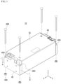
- Fig. 1 is a perspective view showing a conventional battery module
- Fig. 2 is a cross-sectional view taken along the cutting line A-A' of Fig. 1
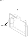
- Fig. 3 is a perspective view showing an end plate included in the battery module of Fig. 1 .
- Fig. 3 shows the surface of the end plate facing the battery cell.
- a conventional battery module 10 can be manufactured by housing a plurality of battery cells 20 in a module frame 30, and then joining an end plate 40 to the module frame 30.
- each battery module 10 can be fixed to a structure such as a pack frame (not shown).
- the conventional battery module 10 may be fixed by forming a mounting structure at four corners. Specifically, mounting holes 40H into which bolts 40B can be inserted can be formed at both ends of the end plate 40 of the battery module 10. The bolt 40B is inserted in the downward direction into the mounting hole 40H, and the nut 40N is coupled to the end of the bolt 40B, so that the battery module 10 can be fixed to the pack frame or the like.
- the mounting hole 40H has a form that extends along a height direction (a direction parallel to the z-axis) as shown in the figure. Therefore, referring to Figs. 2 and 3 , waste of the space occurs as much as the space in which the mounting hole 40H is formed between the end plate 40 and the battery cells 20. That is, in order to fix the battery module 10, mounting holes 40H that extend along the height direction were formed at both ends of the end plate 40, but this caused the deterioration of the space utilization of the battery module 10.
- Increasing the space utilization of the battery module is directly linked to the performance of the battery pack, such as increasing the energy density of the battery module and the battery pack including the same, or enabling downsizing of the battery pack, there is a need to improve the space utilization of the battery module.
- a mounting hole is provided at the lower side of the battery module, and the height of the mounting part is adjusted, thereby capable of forming a mounting structure and at the same time, providing an additional space therein and increasing space utilization.
- planar when referred to as “planar”, it means when a target portion is viewed from the upper side, and when referred to as “cross-sectional”, it means when a target portion is viewed from the side of a cross section cut vertically.
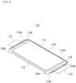
- Fig. 4 is a perspective view showing a battery module used in a battery pack according to an embodiment of the present disclosure.
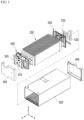
- Fig. 5 is an exploded perspective view of the battery module of Fig. 4 .
- Fig. 6 is a perspective view of a battery cell included in the battery module of Fig. 5 .
- a battery module 100 includes a battery cell stack 200 in which a plurality of battery cells 110 are stacked, a module frame 300 that houses the battery cell stack 200 is open on two opposing surfaces, and end plates 400 cover the open surfaces of the module frame 300.
- the battery cell 110 is preferably a pouch-type battery cell, and may be formed in a rectangular sheet-like structure.
- the battery cell 110 according to the present embodiment has a structure in which the two electrode leads 111 and 112 face each other and protrude from one end and the other end, respectively.
- the battery cell 110 has a structure in which the two electrode leads 111 and 112 face each other and protrude from one end 114a and the other end 114b, respectively. More specifically, the electrode leads 111 and 112 are connected to an electrode assembly (not shown) and are protruded from the electrode assembly (not shown) to the outside of the battery cell 110.
- the battery cell 110 can be manufactured by joining both ends 114a and 114b of a cell case 114 and one side portion 114c connecting them in a state in which an electrode assembly (not shown) is housed in a cell case 114.
- the battery cells 110 according to the present embodiment have a total of three sealing portions 114sa, 114sb and 114sc, the sealing portions 114sa, 114sb and 114sc have a structure that is sealed by a method such as heat-sealing, and the remaining other one side portion can be composed of a connection part 115.
- the cell case 114 can be composed of a laminated sheet including a resin layer and a metal layer.
- connection portion 115 may extend long along one edge of the battery cell 110, and a protrusion portion 110p of the battery cell 110 called a bat-ear may be formed at an end portion of the connection part 115.
- the protrusion portion 110p is an exemplary structure, and the battery cell 110 according to another embodiment of the present disclosure may have a form in which a protrusion portion is not formed and the connection portion 115 extends in a straight line.
- a plurality of battery cells 110 are stacked so as to be electrically connected to each other, thereby forming a battery cell stack 200. Particularly, as shown in Fig. 5 , the plurality of battery cells 110 can be stacked along the y-axis direction. Thereby, one electrode lead 111 of the battery cells 110 may be protruded toward the x-axis direction, and the other electrode lead 112 may protrude toward the -x-axis direction.
- the module frame 300 is open at one surface and at another surface facing the one surface. More specifically, the module frame 300 is opened in both directions in which the electrode leads 111 and 112 protrude with respect to the battery cell stack 200.
- the end plates 400 cover the open surfaces of the module frame 300, respectively.
- the battery cell stack 200 is housed in the module frame 300 and the end plates 400 being thereby capable of physically protecting the battery cell stack 200.
- the module frame 300 and the end plates 400 may include a metal material having a predetermined strength. Meanwhile, the module frame 300 and the end plates 400 may be joined by a method such as welding in a state in which corresponding corner portions are in contact with each other.
- the battery module 100 further includes a busbar frame 500 on which a busbar 510 and a terminal busbar 520 are mounted.
- the busbar 510 and the terminal busbar 520 can be joined to the electrode leads 111 and 112 of the battery cells 110 in order to electrically connect the plurality of battery cells 110.
- the busbar frame 500 on which the busbar 510 and the terminal busbar 520 are mounted can be disposed on the one surface (x-axis direction) and the other surface (-x-axis direction) of the battery cell stack 200.
- the one surface (x-axis direction) and the other surface (-x-axis direction) of the battery cell stack 200 correspond to the surfaces in the direction in which the electrode leads 111 and 112 of the battery cells 110 protrude.
- the busbar frame 500 are located between the battery cell stack 200 and the end plates 400.
- a lead slit may be formed at the busbar frame 500, and the electrode leads 111 and 112 can be bent after passing through the lead slit, and joined to the busbar 510 or the terminal busbar 520.
- the joining method is not particularly limited, and weld-joining can be performed as an example.
- a slit may be formed in the busbar 510 or the terminal busbar 520, and the slit may be located so as to correspond to the lead slit of the busbar frame 500.
- the electrode leads 111 and 112 that have passed through the lead slit may be bent by passing through the slit of the busbar 510 or the slit of the terminal bus bar 520.
- a part of the terminal busbar 520 may be exposed to the outside of the battery module 100. Specifically, an opening is formed in the end plate 400 or an insulating cover (not shown), and a part of the terminal busbar 520 may be exposed as shown in Fig. 4 .
- a part of the exposed terminal busbar 520 can be connected to another battery module or a BDU (battery disconnect unit) or the like to realize a high voltage (HV) connection.
- the HV connection is a connection that plays a role of a power source for supplying electric power, and refers to a connection between battery cells or a connection between battery modules.
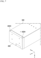
- Fig. 7 is a partial perspective view showing a state in which the lower surface of the battery module of Fig. 4 is inverted so as to face upward.
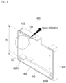
- Fig. 8 is a perspective view of an end plate included in the battery module of Fig. 5 . Particularly, Fig. 8 shows a surface of the end plate facing the battery cell stack.
- the end plate 400 includes a mounting portion 400M in which a mounting hole 400H is formed.
- the mounting hole 400H is opened at the lower surface of the end plate 400, and a thread is formed on the inner surface of the mounting hole 400H.
- the end plate 400 includes a body portion 450, first and second side portions 410 and 420, an upper side portion 430, and a lower side portion 440.
- the body portion 450 is a portion facing the battery cell stack 200
- the first and second side portions 410 and 420, the upper side portion 430, and the lower side portion 440 are portions that are extended in a direction perpendicular to one surface of the body portion 450 from both sides, an upper side, and a lower side of the body portion 450. That is, the end plate 400 according to the present embodiment has a cover shape that is opened in one surface facing the battery cell stack 200.
- the mounting hole 400H according to the present embodiment is opened on the lower surface of the lower portion 440 of the end plate 400, and the mounting portion 400M may extend along a direction parallel to one surface of the body portion 450.
- the bolt inserted into the mounting hole 400H is coupled upwardly to the mounting hole 400H.
- the height h2 of the mounting portion 400M in which the mounting hole is formed may be 0.5 times or less the height h1 of the end plate 400.
- the height h2 of the mounting portion 400M may be 0.3 times or less, more preferably 0.2 times or less the height h1 of the end plate 400. That is, since the mounting hole 400H according to the present embodiment is opened on the lower surface of the lower portion 440 of the end plate 400, the height of the mounting part 400M does not need to be formed in the same manner as the height of the end plate 400, unlike the conventional end plate 40 shown in Fig. 3 .
- the battery module 100 can be sufficiently fixed. Therefore, an empty space can be provided in the upper portion of the mounting portion 400M between the end plate 400 and the battery cell stack 200.
- the lower limit of the height is not particularly limited, but the height h2 of the mounting portion 400M may be 0.05 times or more the height h1 of the end plate 400 in order to have the minimum degree of fastening.
- the conventional battery module 10 has a mounting hole 40H structure that is long in the height direction, and needs to secure a space for mounting and fastening, whereas the battery module 100 according to the present embodiment can implement a mounting hole 400H structure that is short in the height direction, and thus can secure an additional space within the battery module 100. It is possible to utilize the space, such as configuring the conventional wasted space to increase the battery capacity. Because of this advantage in terms of space utilization, the battery module and the battery pack including the same according to the present embodiment can have advantages in terms of energy density or downsizing.
- Fig. 9 is a partial perspective view of a battery module and a pack frame according to an embodiment of the present disclosure.
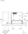
- Fig. 10 is a schematic diagram showing a state in which a battery module according to an embodiment of the present disclosure is mounted on a pack frame.
- the battery pack 1000 includes a battery module 100, a pack frame 1100 that houses the battery module 100, and a bolt 1200 that passes through the through hole 1111H formed in the bottom portion 1110 of the pack frame 1100 to be coupled to the mounting hole 400H.
- the battery modules 100 may be gathered by a plurality of numbers to form a battery pack 1000, wherein each battery module 100 may be fixed to a structure such as the pack frame 1100. At this time, a through hole 1111H is formed in the bottom portion 1110 of the pack frame 1100, and the bolt 1200 passes upwardly through the through hole 1111H, and then can be fastened to the mounting hole 400H of the battery module 100.
- the bottom portion 1110 of the pack frame 1100 may include a mounting plate 1111 for supporting the battery module 100, and a lower plate 1112 located under mounting plate 1111.
- the mounting plate 1111 By forming the above-mentioned through hole 1111H in the mounting plate 1111, it is possible to support the battery module 100 and at the same time, fix the battery module 100 to the mounting plate 1111, thereby forming a mounting structure. That is, the mounting hole 400H of the battery module 100 and the bolt 1200 may be coupled with the mounting plate 1111 being interposed therebetween.
- the lower plate 1112 is located under the mounting plate 1111, and although not specifically shown in the figure, an equipment such as a cooling water supply pipe for supplying cooling the battery module 100 may be provided between the mounting plate 1111 and the lower plate 1112.
- an equipment such as a cooling water supply pipe for supplying cooling the battery module 100 may be provided between the mounting plate 1111 and the lower plate 1112.
- an opening 1112P may be formed in a portion corresponding to the through hole 1111H formed in the mounting plate 1111. That is, an opening 1112P may be formed in each of the portions corresponding to the through hole 1111H with reference to the Z-axis direction.
- the bolt 1200 according to the present embodiment is coupled upwardly to the mounting hole 400H of the battery module 100, but a space is needed for mounting the equipment for assembling the bolt 1200. Therefore, by forming the opening 1112P in the lower plate 1112, a space for assembling the bolt 1200 is provided.
- the pack frame 1100 further includes a side surface portion 1120 located on side surface of the battery module 100 and bottom portion 1110.
- the side surface portion 1120 can form a stepped structure and come into contact with each of the mounting plate 1111 and the lower plate 1112.
- a sealing member 1300 having adhesive properties may be located between the side surface portion 1120 and the mounting plate 1111. That is, the side surface portion 1120 and the mounting plate 1111 are adhered and fixed, and at the same time, a gap therebetween can be sealed by the sealing member 1300.
- the sealing member 1300 according to the present embodiment is located between the side surface portion 1120 and the mounting plate 1111, the space between the side surface portion 1120 and the mounting plate 1111 is sealed even if the opening 1112P is formed, whereby it is possible to prevent water or the like from flowing into the pack frame 1100.
- the material of the sealing member 1300 is not particularly limited. As described above, a space for assembling the bolt 1200 must be secured, such as an opening 1112P being formed in the lower plate 1112, and it is necessary to seal between the mounting plate 1111 and the side surface portion 1120 to prevent the inflow of water. Thus, it is preferable that the sealing member 1300 is located between the side surface portion 1120 and the mounting plate 1111 to be adhered and sealed.
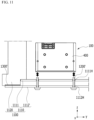
- Fig. 11 is a schematic diagram showing a state in which a battery module according to a modified embodiment of the present disclosure is mounted on a pack frame. Parts overlapping with the above-mentioned contents are omitted in order to avoid repetition of the description.
- the bottom portion 1110 of the pack frame 1100 may include a mounting plate 1111 for supporting the battery module 100 and a lower plate 1112' located under mounting plate 1111.
- the pack frame 1100 may further include a side surface portion 1120 located on the side surface of the battery module 100.
- the lower plate 1112' according to the present embodiment can be formed with a lower through hole 1112H rather than an opening, and the lower through hole 1112H of the lower plate 1112' may be located so as to correspond to the through hole 1111H of the mounting plate 1111 with reference to the Z-axis direction.
- the bolt 1200' according to the present embodiment is formed longer than the bolt 1200 described in Fig. 10 , and after sequentially passing through the lower through hole 1112H of the lower plate 1112' and the through hole 1111H of the mounting plate 1111, it can be coupled to the mounting hole 400H of the battery module 100.
- the adhesive sealing member 1300' according to the present embodiment may be located between the side surface portion 1120 and the lower plate 1112'. Since the lower through hole 1112H of the lower plate 1112' is naturally sealed by the insertion of the bolt 1200' according to the present embodiment, a sealing member 1300' for preventing water from entering the pack frame 1100 can be located between the side surface portion 1120 and the lower plate 1112'. That is, the sealing member 1300' according to the present embodiment can play a function of preventing water inflow while being located between the side surface portion 1120 and the lower plate 1112'. Meanwhile, if necessary, a ring-shaped stopper for sealing may be disposed between the head of the bolt 1200' and the lower plate 1112' according to the present embodiment.
- the one or more battery modules according to embodiments of the present disclosure described above can be mounted together with various control and protection systems such as a battery management system (BMS) and a cooling system to form a battery pack.
- BMS battery management system
- a cooling system to form a battery pack.
- the battery module or the battery pack can be applied to various devices.
- vehicle means such as an electric bike, an electric vehicle, and a hybrid electric vehicle, and may be applied to various devices capable of using a secondary battery, without being limited thereto.
Landscapes
- Chemical & Material Sciences (AREA)
- Chemical Kinetics & Catalysis (AREA)
- Electrochemistry (AREA)
- General Chemical & Material Sciences (AREA)
- Inorganic Chemistry (AREA)
- Battery Mounting, Suspending (AREA)
Claims (9)
- Batteriepack (1000) mit einem Batteriemodul (100), umfassend:einen Batteriezellenstapel (200), in welchem eine Mehrzahl von Batteriezellen (110) gestapelt ist;einen Modulrahmen (300), welcher den Batteriezellenstapel (200) aufnimmt und welcher an seiner einen Fläche geöffnet ist; undEndplatten (400), welche die offenen Flächen des Modulrahmens (300) abdecken,wobei die Endplatten (400) einen Befestigungsabschnitt (400M) umfassen, welcher ein darin gebildetes Befestigungsloch (400H) aufweist, undwobei das Befestigungsloch (400H) an einer unteren Fläche der Endplatte (400) geöffnet ist und ein Gewinde an einer Innenfläche des Befestigungslochs (400H) gebildet ist,einen Packrahmen (1100), welcher das Batteriemodul (100) aufnimmt; undeinen Bolzen (1200), welcher durch ein Durchgangsloch (1111H) verläuft, welches an dem Bodenabschnitt des Packrahmens (1100) gebildet ist, und welcher mit dem Befestigungsloch (400H) gekoppelt ist,dadurch gekennzeichnet, dassder Bodenabschnitt des Packrahmens (1100) eine Befestigungsplatte (1111) zum Haltern des Batteriemoduls (100) und eine untere Platte (1112) umfasst, welche unter der Befestigungsplatte (1111) angeordnet ist, unddas Durchgangsloch (1111H) in der Befestigungsplatte (1111) gebildet ist, und der Bolzen (1200) durch das Durchgangsloch (1111H) der Befestigungsplatte (1111) verläuft, um mit dem Befestigungsloch (400H) gekoppelt zu sein.
- Batteriepack (1000) nach Anspruch 1, wobei:
in der unteren Platte (1112), eine Öffnung (1112P) in einem Abschnitt gebildet ist, welcher dem Durchgangsloch (1111H) entspricht. - Batteriepack (1000) nach Anspruch 1, wobei:der Packrahmen (1100) ferner einen Seitenflächenabschnitt (1120) umfasst, welcher an der Seitenfläche des Batteriemoduls (100) angeordnet ist,der Seitenflächenabschnitt (1120) mit jeder aus der Befestigungsplatte (1111) und der unteren Platte (1112) in Kontakt ist, undein Dichtungselement (1300) zwischen dem Seitenflächenabschnitt (1120) und der Befestigungsplatte (1111) angeordnet ist.
- Batteriepack (1000) nach Anspruch 1, wobei:ein unteres Durchgangsloch (1112H) in der unteren Platte (1112) gebildet ist, undder Bolzen (1200) durch das untere Durchgangsloch (1112H) der unteren Platte (1112) und das Durchgangsloch (1111H) der Befestigungsplatte (1111) verläuft, um mit dem Befestigungsloch (400H) gekoppelt zu sein.
- Batteriepack (1000) nach Anspruch 1, wobei:eine Höhe des Befestigungsabschnitts (400M) 0,5-mal oder geringer als eine Höhe der Endplatte (400) ist, undzwischen der Endplatte (400) und dem Batteriezellenstapel (200) ein leerer Raum in dem oberen Abschnitt der Befestigungsplatte (400M) bereitgestellt ist.
- Batteriepack (1000) nach Anspruch 1, wobei:die Endplatte (400) einen Körperabschnitt (450), einen ersten und zweiten Seitenabschnitt (410, 420), einen oberen Seitenabschnitt (430) und einen unteren Seitenabschnitt (440) umfasst,der Körperabschnitt (450) dem Batteriezellenstapel (200) zugewandt ist, undder erste und zweite Seitenabschnitt (410, 420), der obere Seitenabschnitt (430) und der untere Seitenabschnitt (440) jeweils in einer Richtung erweitert sind, welche von beiden Seiten, einer oberen Seite und einer unteren Seite des Körperabschnitts (450), senkrecht zu einer Fläche des Körperabschnitts (450) ist.
- Batteriepack (1000) nach Anspruch 6, wobei:das Befestigungsloch (400H) an einer unteren Fläche des unteren Seitenabschnitts der Endplatte (400) geöffnet ist, undder Befestigungsabschnitt (400M) entlang einer Richtung erweitert ist, welche parallel zu der einen Fläche des Körperabschnitts (450) ist.
- Batteriepack (1000) nach Anspruch 1, wobei:der Modulrahmen (300) an seiner anderen Fläche geöffnet ist, welche der einen Fläche zugewandt ist, unddie Endplatten (400) jeweils die offenen Flächen des Modulrahmens (300) abdecken.
- Batteriepack (1000) nach Anspruch 1, wobei:
der Bolzen (1200) nach oben mit dem Befestigungsloch (400H) gekoppelt ist.
Applications Claiming Priority (2)
| Application Number | Priority Date | Filing Date | Title |
|---|---|---|---|
| KR1020200153468A KR20220067118A (ko) | 2020-11-17 | 2020-11-17 | 전지 모듈 및 이를 포함하는 전지팩 |
| PCT/KR2021/014961 WO2022108145A1 (ko) | 2020-11-17 | 2021-10-22 | 전지 모듈 및 이를 포함하는 전지팩 |
Publications (3)
| Publication Number | Publication Date |
|---|---|
| EP4199208A1 EP4199208A1 (de) | 2023-06-21 |
| EP4199208A4 EP4199208A4 (de) | 2024-02-21 |
| EP4199208B1 true EP4199208B1 (de) | 2025-04-16 |
Family
ID=81709189
Family Applications (1)
| Application Number | Title | Priority Date | Filing Date |
|---|---|---|---|
| EP21894917.0A Active EP4199208B1 (de) | 2020-11-17 | 2021-10-22 | Batteriepack |
Country Status (8)
| Country | Link |
|---|---|
| US (1) | US20230344061A1 (de) |
| EP (1) | EP4199208B1 (de) |
| JP (1) | JP7590032B2 (de) |
| KR (1) | KR20220067118A (de) |
| CN (1) | CN116195115A (de) |
| ES (1) | ES3026514T3 (de) |
| HU (1) | HUE071290T2 (de) |
| WO (1) | WO2022108145A1 (de) |
Families Citing this family (7)
| Publication number | Priority date | Publication date | Assignee | Title |
|---|---|---|---|---|
| KR102937927B1 (ko) * | 2020-09-22 | 2026-03-10 | 주식회사 엘지에너지솔루션 | 전지 모듈 및 이를 포함하는 전지팩 |
| KR102945051B1 (ko) * | 2020-09-22 | 2026-03-26 | 주식회사 엘지에너지솔루션 | 전지 모듈 및 이를 포함하는 전지팩 |
| CN218385603U (zh) * | 2022-10-10 | 2023-01-24 | 中创新航科技股份有限公司 | 一种电池组及电池包 |
| KR20240156025A (ko) * | 2023-04-21 | 2024-10-29 | 스탠다드에너지(주) | 이차전지 모듈 및 이를 포함하는 이차전지 |
| WO2025246027A1 (zh) * | 2024-05-31 | 2025-12-04 | 惠州亿纬锂能股份有限公司 | 电池包箱体及电池包 |
| CN118486976B (zh) * | 2024-05-31 | 2026-01-13 | 惠州亿纬锂能股份有限公司 | 电池包箱体及电池包 |
| KR20260047683A (ko) * | 2024-10-02 | 2026-04-09 | 주식회사 엘지에너지솔루션 | 팩 케이스 장착이 용이한 배터리 모듈, 및 이를 포함하는 배터리 팩 |
Family Cites Families (11)
| Publication number | Priority date | Publication date | Assignee | Title |
|---|---|---|---|---|
| US8465866B2 (en) * | 2010-04-21 | 2013-06-18 | Samsung Sdi Co., Ltd. | Battery module including a pressure control unit |
| KR101292984B1 (ko) * | 2011-08-22 | 2013-08-02 | 로베르트 보쉬 게엠베하 | 배터리 모듈 |
| KR101511024B1 (ko) * | 2012-08-07 | 2015-04-17 | 주식회사 엘지화학 | 조립형 모듈 케이스를 포함하는 전지모듈 |
| KR102047481B1 (ko) * | 2015-10-30 | 2019-11-21 | 주식회사 엘지화학 | 배터리 모듈 및 이를 포함하는 배터리 팩 |
| US10516145B2 (en) * | 2016-01-26 | 2019-12-24 | Ford Global Technologies, Llc | Battery pack array retention |
| KR102178762B1 (ko) * | 2016-12-23 | 2020-11-13 | 주식회사 엘지화학 | 플라스틱 레이저 용접을 이용한 배터리 모듈과 팩 하우징의 고정구조 |
| KR102162968B1 (ko) * | 2017-04-07 | 2020-10-07 | 주식회사 엘지화학 | 확장형 배터리 모듈 구조를 갖는 배터리 팩 |
| JP7027255B2 (ja) * | 2018-05-31 | 2022-03-01 | 本田技研工業株式会社 | バッテリパック |
| CN208923207U (zh) * | 2018-11-01 | 2019-05-31 | 宁德时代新能源科技股份有限公司 | 一种电池模组端板及其电池模组 |
| CN113169406B (zh) * | 2018-11-28 | 2023-05-26 | 三洋电机株式会社 | 电池组件 |
| CN209344284U (zh) * | 2019-02-26 | 2019-09-03 | 宁德时代新能源科技股份有限公司 | 一种电池模组 |
-
2020
- 2020-11-17 KR KR1020200153468A patent/KR20220067118A/ko not_active Ceased
-
2021
- 2021-10-22 EP EP21894917.0A patent/EP4199208B1/de active Active
- 2021-10-22 US US18/026,510 patent/US20230344061A1/en active Pending
- 2021-10-22 JP JP2023516230A patent/JP7590032B2/ja active Active
- 2021-10-22 HU HUE21894917A patent/HUE071290T2/hu unknown
- 2021-10-22 CN CN202180063070.XA patent/CN116195115A/zh active Pending
- 2021-10-22 WO PCT/KR2021/014961 patent/WO2022108145A1/ko not_active Ceased
- 2021-10-22 ES ES21894917T patent/ES3026514T3/es active Active
Also Published As
| Publication number | Publication date |
|---|---|
| EP4199208A4 (de) | 2024-02-21 |
| JP7590032B2 (ja) | 2024-11-26 |
| JP2023541159A (ja) | 2023-09-28 |
| EP4199208A1 (de) | 2023-06-21 |
| US20230344061A1 (en) | 2023-10-26 |
| CN116195115A (zh) | 2023-05-30 |
| KR20220067118A (ko) | 2022-05-24 |
| WO2022108145A1 (ko) | 2022-05-27 |
| ES3026514T3 (en) | 2025-06-11 |
| HUE071290T2 (hu) | 2025-08-28 |
Similar Documents
| Publication | Publication Date | Title |
|---|---|---|
| EP4199208B1 (de) | Batteriepack | |
| US12407042B2 (en) | Battery module and battery pack including the same | |
| US12327850B2 (en) | Battery module and battery pack including the same | |
| EP4184706B1 (de) | Batteriemodul, batteriepack damit und herstellungsverfahren dafür | |
| US20230395946A1 (en) | Battery module and manufacturing method of the same | |
| EP4195365A1 (de) | Batteriemodul und batteriepack damit | |
| US20230069153A1 (en) | Battery Module, Battery Pack Including The Same And Manufacturing Method Of The Same | |
| US20240106026A1 (en) | Battery module and battery pack including the same | |
| EP4210154A1 (de) | Batteriepack und vorrichtung damit | |
| EP4181275B1 (de) | Batteriemodul und batteriepack damit | |
| EP4044341A1 (de) | Batteriemodul und batteriepack damit | |
| EP4089813A1 (de) | Batteriepack und vorrichtung damit | |
| EP4539227A1 (de) | Batteriepack und vorrichtung damit | |
| EP4181296B1 (de) | Batteriepack und vorrichtung damit | |
| EP4181286B1 (de) | Batteriemodul und batteriepack damit | |
| EP4261985A1 (de) | Batteriepack und vorrichtung damit | |
| KR20230083604A (ko) | 셀 단위체 및 이를 포함하는 전지 팩 | |
| EP4607670A1 (de) | Batteriemodul und batteriepack damit | |
| EP4607672A1 (de) | Batteriemodul und batteriepack damit | |
| EP4250463B1 (de) | Batteriemodul und batteriepack damit | |
| EP4531183A1 (de) | Batteriemodul und batteriepack damit | |
| KR20240012307A (ko) | 전지셀 유닛 및 이를 포함하는 전지셀 어셈블리 |
Legal Events
| Date | Code | Title | Description |
|---|---|---|---|
| STAA | Information on the status of an ep patent application or granted ep patent |
Free format text: STATUS: THE INTERNATIONAL PUBLICATION HAS BEEN MADE |
|
| PUAI | Public reference made under article 153(3) epc to a published international application that has entered the european phase |
Free format text: ORIGINAL CODE: 0009012 |
|
| STAA | Information on the status of an ep patent application or granted ep patent |
Free format text: STATUS: REQUEST FOR EXAMINATION WAS MADE |
|
| 17P | Request for examination filed |
Effective date: 20230314 |
|
| AK | Designated contracting states |
Kind code of ref document: A1 Designated state(s): AL AT BE BG CH CY CZ DE DK EE ES FI FR GB GR HR HU IE IS IT LI LT LU LV MC MK MT NL NO PL PT RO RS SE SI SK SM TR |
|
| A4 | Supplementary search report drawn up and despatched |
Effective date: 20240123 |
|
| DAV | Request for validation of the european patent (deleted) | ||
| DAX | Request for extension of the european patent (deleted) | ||
| RIC1 | Information provided on ipc code assigned before grant |
Ipc: H01M 50/244 20210101ALI20240117BHEP Ipc: H01M 50/271 20210101ALI20240117BHEP Ipc: H01M 50/264 20210101ALI20240117BHEP Ipc: H01M 50/262 20210101ALI20240117BHEP Ipc: H01M 50/224 20210101ALI20240117BHEP Ipc: H01M 50/211 20210101ALI20240117BHEP Ipc: H01M 50/209 20210101ALI20240117BHEP Ipc: H01M 50/204 20210101ALI20240117BHEP Ipc: H01M 50/20 20210101AFI20240117BHEP |
|
| GRAP | Despatch of communication of intention to grant a patent |
Free format text: ORIGINAL CODE: EPIDOSNIGR1 |
|
| STAA | Information on the status of an ep patent application or granted ep patent |
Free format text: STATUS: GRANT OF PATENT IS INTENDED |
|
| INTG | Intention to grant announced |
Effective date: 20240919 |
|
| GRAJ | Information related to disapproval of communication of intention to grant by the applicant or resumption of examination proceedings by the epo deleted |
Free format text: ORIGINAL CODE: EPIDOSDIGR1 |
|
| STAA | Information on the status of an ep patent application or granted ep patent |
Free format text: STATUS: REQUEST FOR EXAMINATION WAS MADE |
|
| P01 | Opt-out of the competence of the unified patent court (upc) registered |
Free format text: CASE NUMBER: APP_56692/2024 Effective date: 20241017 |
|
| GRAP | Despatch of communication of intention to grant a patent |
Free format text: ORIGINAL CODE: EPIDOSNIGR1 |
|
| STAA | Information on the status of an ep patent application or granted ep patent |
Free format text: STATUS: GRANT OF PATENT IS INTENDED |
|
| INTC | Intention to grant announced (deleted) | ||
| INTG | Intention to grant announced |
Effective date: 20241129 |
|
| GRAS | Grant fee paid |
Free format text: ORIGINAL CODE: EPIDOSNIGR3 |
|
| GRAA | (expected) grant |
Free format text: ORIGINAL CODE: 0009210 |
|
| STAA | Information on the status of an ep patent application or granted ep patent |
Free format text: STATUS: THE PATENT HAS BEEN GRANTED |
|
| AK | Designated contracting states |
Kind code of ref document: B1 Designated state(s): AL AT BE BG CH CY CZ DE DK EE ES FI FR GB GR HR HU IE IS IT LI LT LU LV MC MK MT NL NO PL PT RO RS SE SI SK SM TR |
|
| REG | Reference to a national code |
Ref country code: GB Ref legal event code: FG4D |
|
| REG | Reference to a national code |
Ref country code: CH Ref legal event code: EP Ref country code: DE Ref legal event code: R096 Ref document number: 602021029401 Country of ref document: DE |
|
| REG | Reference to a national code |
Ref country code: IE Ref legal event code: FG4D |
|
| REG | Reference to a national code |
Ref country code: ES Ref legal event code: FG2A Ref document number: 3026514 Country of ref document: ES Kind code of ref document: T3 Effective date: 20250611 |
|
| REG | Reference to a national code |
Ref country code: NL Ref legal event code: MP Effective date: 20250416 |
|
| REG | Reference to a national code |
Ref country code: HU Ref legal event code: AG4A Ref document number: E071290 Country of ref document: HU |
|
| PG25 | Lapsed in a contracting state [announced via postgrant information from national office to epo] |
Ref country code: NL Free format text: LAPSE BECAUSE OF FAILURE TO SUBMIT A TRANSLATION OF THE DESCRIPTION OR TO PAY THE FEE WITHIN THE PRESCRIBED TIME-LIMIT Effective date: 20250416 |
|
| REG | Reference to a national code |
Ref country code: AT Ref legal event code: MK05 Ref document number: 1786436 Country of ref document: AT Kind code of ref document: T Effective date: 20250416 |
|
| PG25 | Lapsed in a contracting state [announced via postgrant information from national office to epo] |
Ref country code: FI Free format text: LAPSE BECAUSE OF FAILURE TO SUBMIT A TRANSLATION OF THE DESCRIPTION OR TO PAY THE FEE WITHIN THE PRESCRIBED TIME-LIMIT Effective date: 20250416 Ref country code: PT Free format text: LAPSE BECAUSE OF FAILURE TO SUBMIT A TRANSLATION OF THE DESCRIPTION OR TO PAY THE FEE WITHIN THE PRESCRIBED TIME-LIMIT Effective date: 20250818 |
|
| REG | Reference to a national code |
Ref country code: LT Ref legal event code: MG9D |
|
| PG25 | Lapsed in a contracting state [announced via postgrant information from national office to epo] |
Ref country code: NO Free format text: LAPSE BECAUSE OF FAILURE TO SUBMIT A TRANSLATION OF THE DESCRIPTION OR TO PAY THE FEE WITHIN THE PRESCRIBED TIME-LIMIT Effective date: 20250716 Ref country code: GR Free format text: LAPSE BECAUSE OF FAILURE TO SUBMIT A TRANSLATION OF THE DESCRIPTION OR TO PAY THE FEE WITHIN THE PRESCRIBED TIME-LIMIT Effective date: 20250717 |
|
| PG25 | Lapsed in a contracting state [announced via postgrant information from national office to epo] |
Ref country code: PL Free format text: LAPSE BECAUSE OF FAILURE TO SUBMIT A TRANSLATION OF THE DESCRIPTION OR TO PAY THE FEE WITHIN THE PRESCRIBED TIME-LIMIT Effective date: 20250416 |
|
| PG25 | Lapsed in a contracting state [announced via postgrant information from national office to epo] |
Ref country code: BG Free format text: LAPSE BECAUSE OF FAILURE TO SUBMIT A TRANSLATION OF THE DESCRIPTION OR TO PAY THE FEE WITHIN THE PRESCRIBED TIME-LIMIT Effective date: 20250416 |
|
| PGFP | Annual fee paid to national office [announced via postgrant information from national office to epo] |
Ref country code: BE Payment date: 20250922 Year of fee payment: 5 Ref country code: GB Payment date: 20250922 Year of fee payment: 5 |
|
| PG25 | Lapsed in a contracting state [announced via postgrant information from national office to epo] |
Ref country code: HR Free format text: LAPSE BECAUSE OF FAILURE TO SUBMIT A TRANSLATION OF THE DESCRIPTION OR TO PAY THE FEE WITHIN THE PRESCRIBED TIME-LIMIT Effective date: 20250416 |
|
| PG25 | Lapsed in a contracting state [announced via postgrant information from national office to epo] |
Ref country code: AT Free format text: LAPSE BECAUSE OF FAILURE TO SUBMIT A TRANSLATION OF THE DESCRIPTION OR TO PAY THE FEE WITHIN THE PRESCRIBED TIME-LIMIT Effective date: 20250416 |
|
| PGFP | Annual fee paid to national office [announced via postgrant information from national office to epo] |
Ref country code: FR Payment date: 20250925 Year of fee payment: 5 |
|
| PG25 | Lapsed in a contracting state [announced via postgrant information from national office to epo] |
Ref country code: RS Free format text: LAPSE BECAUSE OF FAILURE TO SUBMIT A TRANSLATION OF THE DESCRIPTION OR TO PAY THE FEE WITHIN THE PRESCRIBED TIME-LIMIT Effective date: 20250716 |
|
| PG25 | Lapsed in a contracting state [announced via postgrant information from national office to epo] |
Ref country code: IS Free format text: LAPSE BECAUSE OF FAILURE TO SUBMIT A TRANSLATION OF THE DESCRIPTION OR TO PAY THE FEE WITHIN THE PRESCRIBED TIME-LIMIT Effective date: 20250816 |
|
| PG25 | Lapsed in a contracting state [announced via postgrant information from national office to epo] |
Ref country code: LV Free format text: LAPSE BECAUSE OF FAILURE TO SUBMIT A TRANSLATION OF THE DESCRIPTION OR TO PAY THE FEE WITHIN THE PRESCRIBED TIME-LIMIT Effective date: 20250416 |
|
| PGFP | Annual fee paid to national office [announced via postgrant information from national office to epo] |
Ref country code: HU Payment date: 20251029 Year of fee payment: 5 |
|
| PGFP | Annual fee paid to national office [announced via postgrant information from national office to epo] |
Ref country code: DE Payment date: 20250922 Year of fee payment: 5 |
|
| PG25 | Lapsed in a contracting state [announced via postgrant information from national office to epo] |
Ref country code: SM Free format text: LAPSE BECAUSE OF FAILURE TO SUBMIT A TRANSLATION OF THE DESCRIPTION OR TO PAY THE FEE WITHIN THE PRESCRIBED TIME-LIMIT Effective date: 20250416 Ref country code: DK Free format text: LAPSE BECAUSE OF FAILURE TO SUBMIT A TRANSLATION OF THE DESCRIPTION OR TO PAY THE FEE WITHIN THE PRESCRIBED TIME-LIMIT Effective date: 20250416 |
|
| REG | Reference to a national code |
Ref country code: DE Ref legal event code: R097 Ref document number: 602021029401 Country of ref document: DE |
|
| PG25 | Lapsed in a contracting state [announced via postgrant information from national office to epo] |
Ref country code: CZ Free format text: LAPSE BECAUSE OF FAILURE TO SUBMIT A TRANSLATION OF THE DESCRIPTION OR TO PAY THE FEE WITHIN THE PRESCRIBED TIME-LIMIT Effective date: 20250416 |
|
| PG25 | Lapsed in a contracting state [announced via postgrant information from national office to epo] |
Ref country code: EE Free format text: LAPSE BECAUSE OF FAILURE TO SUBMIT A TRANSLATION OF THE DESCRIPTION OR TO PAY THE FEE WITHIN THE PRESCRIBED TIME-LIMIT Effective date: 20250416 |
|
| PG25 | Lapsed in a contracting state [announced via postgrant information from national office to epo] |
Ref country code: SK Free format text: LAPSE BECAUSE OF FAILURE TO SUBMIT A TRANSLATION OF THE DESCRIPTION OR TO PAY THE FEE WITHIN THE PRESCRIBED TIME-LIMIT Effective date: 20250416 |
|
| PG25 | Lapsed in a contracting state [announced via postgrant information from national office to epo] |
Ref country code: IT Free format text: LAPSE BECAUSE OF FAILURE TO SUBMIT A TRANSLATION OF THE DESCRIPTION OR TO PAY THE FEE WITHIN THE PRESCRIBED TIME-LIMIT Effective date: 20250416 |
|
| PGFP | Annual fee paid to national office [announced via postgrant information from national office to epo] |
Ref country code: ES Payment date: 20251117 Year of fee payment: 5 |
|
| PLBE | No opposition filed within time limit |
Free format text: ORIGINAL CODE: 0009261 |
|
| STAA | Information on the status of an ep patent application or granted ep patent |
Free format text: STATUS: NO OPPOSITION FILED WITHIN TIME LIMIT |
|
| REG | Reference to a national code |
Ref country code: CH Ref legal event code: L10 Free format text: ST27 STATUS EVENT CODE: U-0-0-L10-L00 (AS PROVIDED BY THE NATIONAL OFFICE) Effective date: 20260225 |
|
| PG25 | Lapsed in a contracting state [announced via postgrant information from national office to epo] |
Ref country code: RO Free format text: LAPSE BECAUSE OF FAILURE TO SUBMIT A TRANSLATION OF THE DESCRIPTION OR TO PAY THE FEE WITHIN THE PRESCRIBED TIME-LIMIT Effective date: 20250416 |
|
| 26N | No opposition filed |
Effective date: 20260119 |