EP4199199B1 - Secondary battery - Google Patents
Secondary battery Download PDFInfo
- Publication number
- EP4199199B1 EP4199199B1 EP22210968.8A EP22210968A EP4199199B1 EP 4199199 B1 EP4199199 B1 EP 4199199B1 EP 22210968 A EP22210968 A EP 22210968A EP 4199199 B1 EP4199199 B1 EP 4199199B1
- Authority
- EP
- European Patent Office
- Prior art keywords
- cap plate
- secondary battery
- region
- plate
- crimping part
- Prior art date
- Legal status (The legal status is an assumption and is not a legal conclusion. Google has not performed a legal analysis and makes no representation as to the accuracy of the status listed.)
- Active
Links
Images


Classifications
-
- H—ELECTRICITY
- H01—ELECTRIC ELEMENTS
- H01M—PROCESSES OR MEANS, e.g. BATTERIES, FOR THE DIRECT CONVERSION OF CHEMICAL ENERGY INTO ELECTRICAL ENERGY
- H01M50/00—Constructional details or processes of manufacture of the non-active parts of electrochemical cells other than fuel cells, e.g. hybrid cells
- H01M50/10—Primary casings; Jackets or wrappings
- H01M50/147—Lids or covers
- H01M50/148—Lids or covers characterised by their shape
- H01M50/152—Lids or covers characterised by their shape for cells having curved cross-section, e.g. round or elliptic
-
- H—ELECTRICITY
- H01—ELECTRIC ELEMENTS
- H01M—PROCESSES OR MEANS, e.g. BATTERIES, FOR THE DIRECT CONVERSION OF CHEMICAL ENERGY INTO ELECTRICAL ENERGY
- H01M10/00—Secondary cells; Manufacture thereof
- H01M10/04—Construction or manufacture in general
- H01M10/0422—Cells or battery with cylindrical casing
-
- H—ELECTRICITY
- H01—ELECTRIC ELEMENTS
- H01M—PROCESSES OR MEANS, e.g. BATTERIES, FOR THE DIRECT CONVERSION OF CHEMICAL ENERGY INTO ELECTRICAL ENERGY
- H01M10/00—Secondary cells; Manufacture thereof
- H01M10/05—Accumulators with non-aqueous electrolyte
- H01M10/052—Li-accumulators
-
- H—ELECTRICITY
- H01—ELECTRIC ELEMENTS
- H01M—PROCESSES OR MEANS, e.g. BATTERIES, FOR THE DIRECT CONVERSION OF CHEMICAL ENERGY INTO ELECTRICAL ENERGY
- H01M50/00—Constructional details or processes of manufacture of the non-active parts of electrochemical cells other than fuel cells, e.g. hybrid cells
- H01M50/10—Primary casings; Jackets or wrappings
- H01M50/102—Primary casings; Jackets or wrappings characterised by their shape or physical structure
- H01M50/107—Primary casings; Jackets or wrappings characterised by their shape or physical structure having curved cross-section, e.g. round or elliptic
-
- H—ELECTRICITY
- H01—ELECTRIC ELEMENTS
- H01M—PROCESSES OR MEANS, e.g. BATTERIES, FOR THE DIRECT CONVERSION OF CHEMICAL ENERGY INTO ELECTRICAL ENERGY
- H01M50/00—Constructional details or processes of manufacture of the non-active parts of electrochemical cells other than fuel cells, e.g. hybrid cells
- H01M50/10—Primary casings; Jackets or wrappings
- H01M50/147—Lids or covers
- H01M50/166—Lids or covers characterised by the methods of assembling casings with lids
- H01M50/167—Lids or covers characterised by the methods of assembling casings with lids by crimping
-
- H—ELECTRICITY
- H01—ELECTRIC ELEMENTS
- H01M—PROCESSES OR MEANS, e.g. BATTERIES, FOR THE DIRECT CONVERSION OF CHEMICAL ENERGY INTO ELECTRICAL ENERGY
- H01M50/00—Constructional details or processes of manufacture of the non-active parts of electrochemical cells other than fuel cells, e.g. hybrid cells
- H01M50/10—Primary casings; Jackets or wrappings
- H01M50/147—Lids or covers
- H01M50/166—Lids or covers characterised by the methods of assembling casings with lids
- H01M50/169—Lids or covers characterised by the methods of assembling casings with lids by welding, brazing or soldering
-
- H—ELECTRICITY
- H01—ELECTRIC ELEMENTS
- H01M—PROCESSES OR MEANS, e.g. BATTERIES, FOR THE DIRECT CONVERSION OF CHEMICAL ENERGY INTO ELECTRICAL ENERGY
- H01M50/00—Constructional details or processes of manufacture of the non-active parts of electrochemical cells other than fuel cells, e.g. hybrid cells
- H01M50/10—Primary casings; Jackets or wrappings
- H01M50/147—Lids or covers
- H01M50/166—Lids or covers characterised by the methods of assembling casings with lids
- H01M50/171—Lids or covers characterised by the methods of assembling casings with lids using adhesives or sealing agents
-
- H—ELECTRICITY
- H01—ELECTRIC ELEMENTS
- H01M—PROCESSES OR MEANS, e.g. BATTERIES, FOR THE DIRECT CONVERSION OF CHEMICAL ENERGY INTO ELECTRICAL ENERGY
- H01M50/00—Constructional details or processes of manufacture of the non-active parts of electrochemical cells other than fuel cells, e.g. hybrid cells
- H01M50/10—Primary casings; Jackets or wrappings
- H01M50/172—Arrangements of electric connectors penetrating the casing
- H01M50/174—Arrangements of electric connectors penetrating the casing adapted for the shape of the cells
- H01M50/179—Arrangements of electric connectors penetrating the casing adapted for the shape of the cells for cells having curved cross-section, e.g. round or elliptic
-
- H—ELECTRICITY
- H01—ELECTRIC ELEMENTS
- H01M—PROCESSES OR MEANS, e.g. BATTERIES, FOR THE DIRECT CONVERSION OF CHEMICAL ENERGY INTO ELECTRICAL ENERGY
- H01M50/00—Constructional details or processes of manufacture of the non-active parts of electrochemical cells other than fuel cells, e.g. hybrid cells
- H01M50/10—Primary casings; Jackets or wrappings
- H01M50/183—Sealing members
- H01M50/184—Sealing members characterised by their shape or structure
-
- H—ELECTRICITY
- H01—ELECTRIC ELEMENTS
- H01M—PROCESSES OR MEANS, e.g. BATTERIES, FOR THE DIRECT CONVERSION OF CHEMICAL ENERGY INTO ELECTRICAL ENERGY
- H01M50/00—Constructional details or processes of manufacture of the non-active parts of electrochemical cells other than fuel cells, e.g. hybrid cells
- H01M50/10—Primary casings; Jackets or wrappings
- H01M50/183—Sealing members
- H01M50/186—Sealing members characterised by the disposition of the sealing members
- H01M50/188—Sealing members characterised by the disposition of the sealing members the sealing members being arranged between the lid and terminal
-
- H—ELECTRICITY
- H01—ELECTRIC ELEMENTS
- H01M—PROCESSES OR MEANS, e.g. BATTERIES, FOR THE DIRECT CONVERSION OF CHEMICAL ENERGY INTO ELECTRICAL ENERGY
- H01M50/00—Constructional details or processes of manufacture of the non-active parts of electrochemical cells other than fuel cells, e.g. hybrid cells
- H01M50/30—Arrangements for facilitating escape of gases
- H01M50/342—Non-re-sealable arrangements
-
- H—ELECTRICITY
- H01—ELECTRIC ELEMENTS
- H01M—PROCESSES OR MEANS, e.g. BATTERIES, FOR THE DIRECT CONVERSION OF CHEMICAL ENERGY INTO ELECTRICAL ENERGY
- H01M50/00—Constructional details or processes of manufacture of the non-active parts of electrochemical cells other than fuel cells, e.g. hybrid cells
- H01M50/50—Current conducting connections for cells or batteries
- H01M50/531—Electrode connections inside a battery casing
-
- H—ELECTRICITY
- H01—ELECTRIC ELEMENTS
- H01M—PROCESSES OR MEANS, e.g. BATTERIES, FOR THE DIRECT CONVERSION OF CHEMICAL ENERGY INTO ELECTRICAL ENERGY
- H01M50/00—Constructional details or processes of manufacture of the non-active parts of electrochemical cells other than fuel cells, e.g. hybrid cells
- H01M50/50—Current conducting connections for cells or batteries
- H01M50/543—Terminals
- H01M50/547—Terminals characterised by the disposition of the terminals on the cells
- H01M50/548—Terminals characterised by the disposition of the terminals on the cells on opposite sides of the cell
-
- H—ELECTRICITY
- H01—ELECTRIC ELEMENTS
- H01M—PROCESSES OR MEANS, e.g. BATTERIES, FOR THE DIRECT CONVERSION OF CHEMICAL ENERGY INTO ELECTRICAL ENERGY
- H01M50/00—Constructional details or processes of manufacture of the non-active parts of electrochemical cells other than fuel cells, e.g. hybrid cells
- H01M50/50—Current conducting connections for cells or batteries
- H01M50/543—Terminals
- H01M50/547—Terminals characterised by the disposition of the terminals on the cells
- H01M50/55—Terminals characterised by the disposition of the terminals on the cells on the same side of the cell
-
- H—ELECTRICITY
- H01—ELECTRIC ELEMENTS
- H01M—PROCESSES OR MEANS, e.g. BATTERIES, FOR THE DIRECT CONVERSION OF CHEMICAL ENERGY INTO ELECTRICAL ENERGY
- H01M50/00—Constructional details or processes of manufacture of the non-active parts of electrochemical cells other than fuel cells, e.g. hybrid cells
- H01M50/50—Current conducting connections for cells or batteries
- H01M50/543—Terminals
- H01M50/552—Terminals characterised by their shape
- H01M50/559—Terminals adapted for cells having curved cross-section, e.g. round, elliptic or button cells
-
- H—ELECTRICITY
- H01—ELECTRIC ELEMENTS
- H01M—PROCESSES OR MEANS, e.g. BATTERIES, FOR THE DIRECT CONVERSION OF CHEMICAL ENERGY INTO ELECTRICAL ENERGY
- H01M50/00—Constructional details or processes of manufacture of the non-active parts of electrochemical cells other than fuel cells, e.g. hybrid cells
- H01M50/50—Current conducting connections for cells or batteries
- H01M50/543—Terminals
- H01M50/564—Terminals characterised by their manufacturing process
- H01M50/567—Terminals characterised by their manufacturing process by fixing means, e.g. screws, rivets or bolts
-
- H—ELECTRICITY
- H01—ELECTRIC ELEMENTS
- H01M—PROCESSES OR MEANS, e.g. BATTERIES, FOR THE DIRECT CONVERSION OF CHEMICAL ENERGY INTO ELECTRICAL ENERGY
- H01M50/00—Constructional details or processes of manufacture of the non-active parts of electrochemical cells other than fuel cells, e.g. hybrid cells
- H01M50/50—Current conducting connections for cells or batteries
- H01M50/572—Means for preventing undesired use or discharge
- H01M50/584—Means for preventing undesired use or discharge for preventing incorrect connections inside or outside the batteries
- H01M50/586—Means for preventing undesired use or discharge for preventing incorrect connections inside or outside the batteries inside the batteries, e.g. incorrect connections of electrodes
-
- H—ELECTRICITY
- H01—ELECTRIC ELEMENTS
- H01M—PROCESSES OR MEANS, e.g. BATTERIES, FOR THE DIRECT CONVERSION OF CHEMICAL ENERGY INTO ELECTRICAL ENERGY
- H01M50/00—Constructional details or processes of manufacture of the non-active parts of electrochemical cells other than fuel cells, e.g. hybrid cells
- H01M50/50—Current conducting connections for cells or batteries
- H01M50/572—Means for preventing undesired use or discharge
- H01M50/584—Means for preventing undesired use or discharge for preventing incorrect connections inside or outside the batteries
- H01M50/59—Means for preventing undesired use or discharge for preventing incorrect connections inside or outside the batteries characterised by the protection means
- H01M50/593—Spacers; Insulating plates
-
- H—ELECTRICITY
- H01—ELECTRIC ELEMENTS
- H01M—PROCESSES OR MEANS, e.g. BATTERIES, FOR THE DIRECT CONVERSION OF CHEMICAL ENERGY INTO ELECTRICAL ENERGY
- H01M2200/00—Safety devices for primary or secondary batteries
- H01M2200/20—Pressure-sensitive devices
-
- Y—GENERAL TAGGING OF NEW TECHNOLOGICAL DEVELOPMENTS; GENERAL TAGGING OF CROSS-SECTIONAL TECHNOLOGIES SPANNING OVER SEVERAL SECTIONS OF THE IPC; TECHNICAL SUBJECTS COVERED BY FORMER USPC CROSS-REFERENCE ART COLLECTIONS [XRACs] AND DIGESTS
- Y02—TECHNOLOGIES OR APPLICATIONS FOR MITIGATION OR ADAPTATION AGAINST CLIMATE CHANGE
- Y02E—REDUCTION OF GREENHOUSE GAS [GHG] EMISSIONS, RELATED TO ENERGY GENERATION, TRANSMISSION OR DISTRIBUTION
- Y02E60/00—Enabling technologies; Technologies with a potential or indirect contribution to GHG emissions mitigation
- Y02E60/10—Energy storage using batteries
Definitions
- the present disclosure relates to a secondary battery.
- Lithium (e.g., lithium ion) secondary batteries are utilized as power sources for hybrid or electric vehicles as well as portable electronic devices owing to several features and/or advantages including, for example, high operating voltage and high energy density per unit weight.
- the secondary batteries may be classified into cylindrical, prismatic, or pouch types (kinds) in shape.
- a cylindrical secondary battery generally includes a cylindrical case, a cylindrical electrode assembly coupled to the case, an electrolyte (optional) injected inside the case to enable movement of lithium ions, and a cap assembly coupled to one side of the case to prevent or reduce leakage of electrolyte and to prevent or reduce separation of the electrode assembly.
- the present disclosure provides a secondary battery according to claim 1. Aspects of one or more embodiments of the present disclosure are directed towards a cylindrical secondary battery in which a positive electrode terminal and a negative electrode terminal are concurrently (e.g., simultaneously) implemented in a cap assembly.
- One or more embodiments of the present disclosure include a secondary battery including: a case including a beading part and a crimping part; an electrode assembly physically coupled to the case and including a first electrode plate and a second electrode plate, the first electrode plate being electrically connected to the case; a first insulating gasket between the beading part and the crimping part; a cap plate coupled between the beading part and the crimping part through the first insulating gasket; a second insulating gasket penetrating (e.g., extending) through and coupled to the cap plate; and a rivet terminal penetrating (e.g., extending) through and physically coupled to the second insulating gasket, and wherein the rivet terminal is electrically connected to the second electrode plate of the electrode assembly.
- a secondary battery including: a case including a beading part and a crimping part; an electrode assembly physically coupled to the case and including a first electrode plate and a second electrode plate, the first electrode
- the crimping part and the cap plate may be connected to each other.
- an outer surface of the crimping part and the cap plate may be connected to each other by a conductive adhesive.
- an inner surface of the crimping part and the cap plate may be connected to each other by a conductive adhesive.
- the crimping part and the cap plate may be connected to each other by a welding region.
- the welding region may be provided on a partial region of the crimping part or may be provided on an entire region of the crimping part.
- an inner insulator may be on an inner surface of the cap plate.
- the cap plate may include: a cap plate-peripheral region coupled between the beading part and the crimping part; a cap plate-inclined region extending from the cap plate-peripheral region and inclined upward; and a cap plate-center region extending from the cap plate-inclined region and coupled to the second insulating gasket and the rivet terminal.
- an outer surface of the crimping part and an outer surface of the cap plate-center region may be coplanar.
- the case may further include a bottom surface, and the bottom surface may include a safety vent.
- the second electrode plate of the electrode assembly may be electrically connected to the rivet terminal through a second lead tab.
- the first electrode plate of the electrode assembly may be electrically connected to the safety vent through a first lead tab.
- first, second, etc. may be used herein to describe one or more suitable members, elements, regions, layers and/or sections, these members, elements, regions, layers and/or sections should not be limited by these terms. These terms are only used to distinguish one member, element, region, layer and/or section from another. Thus, for example, a first member, a first element, a first region, a first layer and/or a first section discussed below could be termed a second member, a second element, a second region, a second layer and/or a second section without departing from the teachings of the present disclosure.
- spatially relative terms such as “beneath,” “below,” “lower,” “above,” “upper,” and the like, may be used herein for ease of description to describe one element or feature's relationship to another element(s) or feature(s) as illustrated in the drawings. It will be understood that the spatially relative terms are intended to encompass different orientations of the device in use or operation in addition to the orientation depicted in the drawings. For example, when the element or feature in the drawings is turned over, elements described as “below” or “beneath” other elements or features would then be oriented “on” or “above” the other elements or features. Thus, the example term “below” can encompass both an orientation of above and below.
- the device may be otherwise oriented (e.g., rotated 90 degrees or at other orientations) and the spatially relative descriptors used herein should be interpreted accordingly.
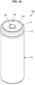
- FIGs. 1A and 1B are a perspective view and a cross-sectional view, respectively, illustrating an example secondary battery 100 according to one or more embodiments of the present disclosure.
- FIG. 2 is an enlarged cross-sectional view illustrating a cap assembly 130 and a structure (e.g., a structure around or a surrounding structure) thereof in the example secondary battery 100 according to one or more embodiments of the present disclosure.
- the example secondary battery 100 includes a cylindrical case 110, a cylindrical electrode assembly 120, and a cap assembly 130.
- the example secondary battery 100 may further include a center pin 140 (optional) coupled to the electrode assembly 120.
- the cylindrical case 110 may include a substantially circular bottom portion 111 and a sidewall 112 extending a set or predetermined length upward from the bottom portion 111.
- the case 110 may include or be referred to as a can, an exterior material, or a housing.
- the upper portion of the cylindrical case 110 may be opened. Accordingly, during the assembling process of the secondary battery 100, the electrode assembly 120 may be integrated into one structure and inserted into the cylindrical case 110. Of course, thereafter, an electrolyte (optional or suitable) may be additionally injected into the cylindrical case 110.
- the cylindrical case 110 may be made of steel, a steel alloy, nickel-plated steel, nickel-plated steel alloy, aluminium, or an aluminium alloy.
- a beading part 113 that is recessed inwardly may be provided at the bottom of the cap assembly 130 and a crimping part 114 that is bent inward may be provided on the upper portion of the cap assembly 130 such that the cap assembly 130 is not separated to the outside (e.g., so that the cap assembly 130 may not be separated from the secondary battery 100 after assembly).
- a safety vent 1111 may be provided at the bottom 111 of the cylindrical case 110.
- the safety vent 1111 may be provided in an approximately or substantially circular ring shape or a C shape.
- the safety vent 1111 may include or be referred to as a notch, recess, or groove.
- the electrode assembly 120 may be accommodated in the cylindrical case 110.
- the electrode assembly 120 may include or be referred to as an electrode, an electrode group, or a jelly roll.
- the electrode assembly 120 may include a negative electrode plate 121 coated with a negative electrode active material (e.g., graphite, carbon, etc.), a positive electrode plate 122 coated with a positive electrode active material (e.g., transition metal oxide(s) (LiCoO 2 , LiNiO 2 , LiMn 2 O 4 , etc.), and a separator 123 positioned between the negative electrode plate 121 and the positive electrode plate 122 to prevent or substantially prevent a short circuit and allow only or substantially or effectively allow only the movement of lithium ions.
- a negative electrode active material e.g., graphite, carbon, etc.
- a positive electrode plate 122 coated with a positive electrode active material e.g., transition metal oxide(s) (LiCoO 2 , LiNiO 2 , LiMn 2 O 4 ,
- the negative electrode plate 121, the positive electrode plate 122, and the separator 123 may be wound in a substantially cylindrical shape.
- the negative electrode plate 121 may include copper (Cu) foil
- the positive electrode plate 122 may include aluminium (Al) foil
- the separator 123 may include polyethylene (PE) or polypropylene (PP).
- a negative electrode lead tab 124 protruding downward by a set or predetermined length may be connected to the negative electrode plate 121, and a positive electrode lead tab 125 protruding upward by a set or predetermined length may be connected to the positive electrode plate 122, or vice versa.
- the negative electrode lead tab 124 may include copper (Cu) or nickel (Ni), and the positive lead tab 125 may include aluminium (Al).
- the negative electrode lead tab 124 of the electrode assembly 120 may be welded to a bottom portion 111 of the cylindrical case 110. Therefore, the cylindrical case 110 may operate as a negative electrode.
- the negative electrode lead tab 124 may be welded to the safety vent 1111 provided on the bottom portion 111 of the cylindrical case 110.
- the positive electrode lead tab 125 may be welded to the bottom portion 111 of the cylindrical case 110, and in this case, the cylindrical case 110 may operate as a positive electrode.
- a first insulating plate 126 coupled to the cylindrical case 110 and having a first hole 126a formed at the center thereof and a second hole 126b formed at the outside thereof may be disposed between the electrode assembly 120 and the bottom portion 111.
- the first insulating plate 126 prevents or protects the electrode assembly 120 from electrically contacting the bottom portion 111 of the cylindrical case 110.
- the first insulating plate 126 prevents or protects the positive electrode plate 122 of the electrode assembly 120 from electrically contacting the bottom portion 111.
- the first hole 126a allows the gas to rapidly move upward through the center pin 140, and the second hole 126b allows the negative electrode lead tab 124 to penetrate (e.g., extend) through and be welded to the bottom portion 111.
- a second insulating plate 127 coupled to the cylindrical case 110 and having a first hole 127a formed at the center thereof and a plurality of second holes 127b formed at the outside thereof may be interposed between the electrode assembly 120 and the cap assembly 130.
- the second insulating plate 127 prevents or protects the electrode assembly 120 from electrically contacting the cap assembly 130.
- the second insulating plate 127 prevents or protects the negative electrode plate 121 of the electrode assembly 120 from electrically contacting the cap assembly 130.
- the first hole 127a allows the gas to rapidly move to the cap assembly 130
- the second holes 127b allow the positive electrode lead tab 125 to penetrate (e.g., extend) through and be welded to the rivet terminal 134.
- the remaining second holes 127b serve to allow an electrolyte to quickly flow into the electrode assembly 120 in an electrolyte injection process.
- the first holes 126a and 127a of the first and second insulating plates 126 and 127 are formed to have smaller diameters than the center pin 140, thereby preventing or substantially preventing the center pin 140 from electrically contacting the bottom portion 111 or the cap assembly 130 due to an external impact.
- the center pin 140 has a hollow circular pipe shape, and may be coupled to approximately the center of the electrode assembly 120.
- the center pin 140 may be formed of steel, stainless steel, aluminium, an aluminium alloy, or polybutylene terephthalate, but the present disclosure is not limited thereto.
- the center pin 140 serves to suppress or reduce deformation of the electrode assembly 120 during charging and discharging of the battery, and serves as a passage for gas generated inside the secondary battery.
- the cap assembly 130 includes a first insulating gasket 131, a cap plate 132, a second insulating gasket 133, and a rivet terminal 134.
- the cap assembly 130 may further include an upper insulator 135, a lower insulator 136, and an inner insulator 137.
- the cap assembly 130 may include or be referred to as a cap, a cap-up, a plate, a cover, a lid, or a shroud.
- the first insulating gasket 131 is interposed between the beading part 113 and the crimping part 114 provided in the case 110.
- the upper end of the first insulating gasket 131 may be positioned between the beading part 113 and the crimping part 114, and the lower end of the first insulating gasket 131 may be positioned inside the beading part 113.
- the first insulating gasket 131 may include an insulator that does not react with an electrolyte.
- the first insulating gasket 131 may include polypropylene (PP), polyethylene (PE), ethylene propylene diene monomer (EPDM), or nitrile butadiene rubber (NBR).
- PP polypropylene
- PE polyethylene
- EPDM ethylene propylene diene monomer
- NBR nitrile butadiene rubber
- the cap plate 132 is coupled between the beading part 113 and the crimping part 114 to be fixed with the first insulating gasket 131 interposed therebetween.
- the cap plate 132 may include a cap plate-peripheral region 1321, a cap plate-inclined region 1322, and a cap plate-center region 1323.
- the cap plate-center region 1323 may include a terminal hole 1324 through which the second insulating gasket 133 and the rivet terminal 134 penetrate (e.g., extend) to be coupled, as discussed in more detail below.
- the cap plate 132 may include aluminium, copper, nickel, iron, or an alloy thereof.
- the cap plate 132 may include or be referred to as a cap, a cap-up, a plate, a cover, a lid, or a shroud.
- the cap plate-peripheral region 1321 may be coupled between the beading part 113 and the crimping part 114.
- the side surface and the inner surface (lower surface) of the cap plate-peripheral region 1321 may be in close contact with the first insulating gasket 131, and the outer surface (upper surface) of the cap plate-peripheral region 1321 may be in close contact with the crimping part 114.
- the outer surface of the cap plate-peripheral region 1321 may be electrically connected to the inner surface of the crimping part 114. Accordingly, the case 110 and the cap plate 130 may have the same polarity.
- the cap plate-inclined region 1322 may extend from the cap plate-peripheral region 1321 and may be inclined upward.
- the cap plate-inclined region 1322 may connect the cap plate-peripheral region 1321 and the cap plate-center region 1323 to each other.
- the cap plate-center region 1323 may extend from the cap plate-inclined region 1322.
- the cap plate-center region 1323 may include a generally flat outer surface (top surface) and an approximately flat inner surface (bottom surface) opposite the outer surface.
- the terminal hole 1324 may penetrate (e.g., extend) through the cap plate-center region 1323.
- the outer surface of the crimping part 114 and the outer surface of the cap plate-center region 1323 may be substantially coplanar.
- the second insulating gasket 133 may be coupled to the terminal hole 1324.
- the second insulating gasket 133 may cover an inner wall of the terminal hole 1324, a portion of the outer surface of the cap plate-center region 1323, and a portion of the inner surface of the cap plate-center region 1323.
- the material of the second insulating gasket 133 may be similar to that of the first insulating gasket 131.
- the second insulating gasket 133 may include or be referred to as a sealing gasket or a sealing insulator.
- the rivet terminal 134 penetrates (e.g., extends) through and is coupled to the second insulating gasket 133. In other words, the rivet terminal 134 may be coupled through the terminal hole 1324 of the cap plate 132.
- the rivet terminal 134 may include a rivet head 1341 positioned on the outer surface of the cap plate 132, a rivet body 1342 positioned inside the terminal hole 1324, and a rivet leg 1343 positioned on (or adjacent) the inner surface of the cap plate 132.
- the rivet head 1341, the rivet body 1342, and the rivet leg 1343 may be integrally provided, and may have a substantially T-shaped cross-section.
- the rivet terminal 134 may include aluminium, copper, nickel, iron, or an alloy thereof.
- the positive electrode lead tab 125 may be electrically connected to the rivet leg 1343 of the rivet terminal 134.
- a positive electrode lead tab 125 may be welded to the rivet leg 1343.
- the rivet terminal 134 may have a positive electrode characteristic.
- the cap plate 132 may serve as a negative electrode terminal, and the rivet terminal 134 may serve as a positive electrode terminal.
- the cap plate 132 may have a negative electrode characteristic by being electrically connected to the crimping part 114 of the case 110, and the rivet terminal 134 may have a positive electrode characteristic by being electrically connected to the positive electrode lead tab 125.
- two terminals are concurrently (e.g., simultaneously) provided at (e.g., in) the upper region (or portion) of the cylindrical secondary battery 100.
- the upper insulator 135 may be provided between the rivet terminal 134 and the cap plate 132. In one or more embodiments, the upper insulator 135 may be interposed between the rivet head 1341 and the cap plate-center region 1323.
- the lower insulator 136 may be interposed between the rivet body 1342 and/or the rivet leg 1343 and the cap plate-center region 1323. In one or more embodiments, the lower insulator 136 may be interposed between the rivet leg 1343 and the second insulating gasket 133 and/or the inner insulator 137.
- An inner insulator 137 may be additionally provided on the inner surface of the cap plate 132. In one or more embodiments, the inner insulator 137 may be provided in the cap plate-center region 1323. In one or more embodiments, the inner insulator 137 may be provided on the inner surface of the cap plate-center region 1323. In one or more embodiments, the inner insulator 137 may be provided from the terminal hole 1324 provided in the cap plate-center region 1323 to the cap plate-inclined region 1322.
- the insulators 135, 136, and 137 may include insulators that do not react with an electrolyte. In one or more embodiments, the insulators 135, 136, and 137 may include PP, PE, EPDM or NBR. In one or more embodiments, the insulators 135, 136, and 137 may be provided by being coated on the cap plate 132 in a liquid state and then cured, or may be provided by being separately provided and then assembled to the cap plate 132.
- FIG. 3 is an enlarged cross-sectional view illustrating a cap assembly 130 and a structure (e.g., a structure around or a surrounding structure) thereof in the example secondary battery 100 according to one or more embodiments of the present disclosure.
- the cap plate 132 and the crimping part 114 may be electrically connected to each other by a conductive adhesive 150A.
- the cap plate-peripheral region 1321, the cap plate-inclined region 1322, and/or the cap plate-center region 1323 may be electrically connected to the outer surface of the crimping part 114 by the conductive adhesive 150A.
- the conductive adhesive 150A may include silver-filled epoxy or solder.
- the conductive adhesive 150A may include a welding region provided by laser welding, resistance welding, arc welding, and/or the like.
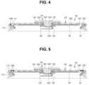
- FIG. 4 is an enlarged cross-sectional view illustrating a cap assembly 130 and a structure (e.g., a structure around or a surrounding structure) thereof in the example secondary battery 100 according to one or more embodiments of the present disclosure.
- the cap plate 132 and the crimping part 114 may be electrically connected to each other by a conductive adhesive 150B.
- the cap plate-peripheral region 1321 may be electrically connected to the inner surface of the crimping part 114 by the conductive adhesive 150B.
- the conductive adhesive 150B may include silver-filled epoxy or solder.
- the conductive adhesive 150B may include a welding region provided by laser welding, resistance welding, arc welding, and/or the like.
- FIG. 5 is an enlarged cross-sectional view illustrating a cap assembly 130 and a structure (e.g., a structure around or a surrounding structure) thereof in the example secondary battery 100 according to one or more embodiments of the present disclosure.
- the crimping part 114 and the cap plate 132 may be electrically connected to each other by a welding region 150C.
- the welding region 150C may be provided by laser beams.
- a partial region of the crimping part 114 and a partial region of the cap plate-peripheral region 1321 are melted and then cooled to provide the welding region 150C, and, by the welding region 150C, the crimping part 114 and the cap plate-peripheral region 1321 may be electrically, mechanically and/or physically connected to each other.
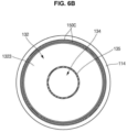
- FIGs. 6A and 6B are enlarged plan views illustrating a cap assembly 130 and a structure (e.g., a structure around or a surrounding structure) thereof in the example secondary battery 100 according to one or more embodiments of the present disclosure.
- the welding region 150C provided by the laser beams may be provided at four portions at intervals of approximately 90° from the outer surface of the crimping part 114. In one or more embodiments, at each portion, the welding region 150C may be provided in the form of two lines. In one or more embodiments, each welding region 150C may be provided in the form of an arc.
- the welding region 150C provided by the laser beams may be provided on the entire outer surface of the crimping part 114 in the form of a circular ring. In one or more embodiments, the welding region 150C may be provided in the form of two circular rings.
- the present disclosure provides a cylindrical secondary battery in which a negative electrode terminal and a positive electrode terminal are concurrently (e.g., simultaneously) implemented in a cap assembly.
- the term “substantially,” “about”, and similar terms are used as terms of approximation and not as terms of degree, and are intended to account for the inherent deviations in measured or calculated values that would be recognized by those of ordinary skill in the art. "Substantially” as used herein, is inclusive of the stated value and means within an acceptable range of deviation for the particular value as determined by one of ordinary skill in the art, considering the measurement in question and the error associated with measurement of the particular quantity (i.e., the limitations of the measurement system). For example, “substantially” may mean within one or more standard deviations, or within ⁇ 30%, 20%, 10%, 5% of the stated value.
Landscapes
- Chemical & Material Sciences (AREA)
- Chemical Kinetics & Catalysis (AREA)
- Electrochemistry (AREA)
- General Chemical & Material Sciences (AREA)
- Engineering & Computer Science (AREA)
- Manufacturing & Machinery (AREA)
- Sealing Battery Cases Or Jackets (AREA)
- Connection Of Batteries Or Terminals (AREA)
Applications Claiming Priority (1)
| Application Number | Priority Date | Filing Date | Title |
|---|---|---|---|
| KR1020210179507A KR102561215B1 (ko) | 2021-12-15 | 2021-12-15 | 이차 전지 |
Publications (2)
| Publication Number | Publication Date |
|---|---|
| EP4199199A1 EP4199199A1 (en) | 2023-06-21 |
| EP4199199B1 true EP4199199B1 (en) | 2025-01-29 |
Family
ID=84387836
Family Applications (1)
| Application Number | Title | Priority Date | Filing Date |
|---|---|---|---|
| EP22210968.8A Active EP4199199B1 (en) | 2021-12-15 | 2022-12-01 | Secondary battery |
Country Status (6)
| Country | Link |
|---|---|
| US (1) | US12469911B2 (pl) |
| EP (1) | EP4199199B1 (pl) |
| KR (2) | KR102561215B1 (pl) |
| CN (1) | CN116264326A (pl) |
| HU (1) | HUE071094T2 (pl) |
| PL (1) | PL4199199T3 (pl) |
Families Citing this family (11)
| Publication number | Priority date | Publication date | Assignee | Title |
|---|---|---|---|---|
| KR102601042B1 (ko) * | 2021-09-10 | 2023-11-13 | 삼성에스디아이 주식회사 | 원통형 이차전지 |
| KR102795258B1 (ko) * | 2023-06-27 | 2025-04-16 | 삼성에스디아이 주식회사 | 이차 전지 |
| KR102895362B1 (ko) * | 2023-06-27 | 2025-12-04 | 삼성에스디아이 주식회사 | 이차 전지 |
| USD1112038S1 (en) * | 2023-09-08 | 2026-02-10 | Xiamen Hithium Energy Storage Technology Co., Ltd. | Battery |
| WO2025110866A1 (ko) * | 2023-11-24 | 2025-05-30 | 주식회사 엘지에너지솔루션 | 원통형 이차전지의 캡가스켓 및 이를 적용한 원통형 이차전지 |
| KR102858241B1 (ko) * | 2023-12-26 | 2025-09-09 | 삼성에스디아이 주식회사 | 이차 전지 |
| KR20250115545A (ko) * | 2024-01-24 | 2025-07-31 | 삼성에스디아이 주식회사 | 이차전지 |
| KR20250143391A (ko) * | 2024-03-25 | 2025-10-02 | 삼성에스디아이 주식회사 | 이차 전지 |
| WO2025244465A1 (ko) * | 2024-05-24 | 2025-11-27 | 주식회사 엘지에너지솔루션 | 하단 냉각이 가능한 원통형 배터리 셀 |
| WO2025249898A1 (ko) * | 2024-05-29 | 2025-12-04 | 삼성에스디아이 주식회사 | 이차 전지 |
| WO2026023970A1 (ko) * | 2024-07-26 | 2026-01-29 | 주식회사 엘지에너지솔루션 | 배터리 셀, 이를 포함하는 배터리 팩 및 자동차 |
Family Cites Families (18)
| Publication number | Priority date | Publication date | Assignee | Title |
|---|---|---|---|---|
| US6204635B1 (en) | 1998-05-22 | 2001-03-20 | Texas Instruments Incorporated | Current interrupt apparatus particularly adapted for use with prismatic electrochemical cells |
| US6844110B2 (en) * | 2000-05-24 | 2005-01-18 | Ngk Insulators, Ltd. | Lithium secondary cell and assembly thereof |
| KR100522819B1 (ko) | 2003-08-18 | 2005-10-18 | 삼성에스디아이 주식회사 | 리튬 이온 2차 전지 |
| EP2400578B1 (en) | 2010-06-25 | 2013-04-03 | Samsung SDI Co., Ltd. | Secondary Battery |
| WO2012121468A1 (ko) | 2011-03-10 | 2012-09-13 | 신흥에스이씨주식회사 | 부품을 접착시킨 캡조립체를 포함하는 이차전지 |
| JP5767407B2 (ja) * | 2011-07-13 | 2015-08-19 | エルジー・ケム・リミテッド | 円筒型二次電池 |
| KR101483700B1 (ko) * | 2011-11-11 | 2015-01-19 | 주식회사 엘지화학 | 이차 전지 및 이를 포함하는 배터리 팩 |
| KR101907215B1 (ko) | 2012-08-08 | 2018-10-11 | 삼성에스디아이 주식회사 | 원통형 리튬 이온 이차 전지 |
| KR102209831B1 (ko) * | 2014-02-20 | 2021-01-29 | 삼성에스디아이 주식회사 | 캡 어셈블리 및 이를 포함하는 이차 전지 |
| KR102586877B1 (ko) | 2016-04-11 | 2023-10-10 | 삼성에스디아이 주식회사 | 이차 전지 |
| JP6868400B2 (ja) | 2017-01-17 | 2021-05-12 | Fdk株式会社 | 筒型電池の封口体、筒型電池 |
| KR102335696B1 (ko) | 2017-11-01 | 2021-12-07 | 주식회사 엘지에너지솔루션 | 전류차단부재 및 캡 조립체 |
| KR102487217B1 (ko) | 2018-02-01 | 2023-01-11 | 주식회사 엘지에너지솔루션 | 리벳을 포함하는 캡 어셈블리 및 이를 포함하는 비딩부/클림핑부가 생략된 원통형 전지 |
| KR102570969B1 (ko) * | 2018-02-01 | 2023-08-25 | 삼성에스디아이 주식회사 | 원통형 리튬 이온 이차 전지 |
| JP7340818B2 (ja) | 2018-11-30 | 2023-09-08 | パナソニックIpマネジメント株式会社 | 電池 |
| KR102757824B1 (ko) | 2019-11-01 | 2025-01-22 | 주식회사 엘지에너지솔루션 | 이차전지 |
| KR102864765B1 (ko) * | 2020-04-13 | 2025-09-24 | 삼성에스디아이 주식회사 | 이차 전지 |
| KR102601042B1 (ko) | 2021-09-10 | 2023-11-13 | 삼성에스디아이 주식회사 | 원통형 이차전지 |
-
2021
- 2021-12-15 KR KR1020210179507A patent/KR102561215B1/ko active Active
-
2022
- 2022-10-27 US US17/975,404 patent/US12469911B2/en active Active
- 2022-12-01 PL PL22210968.8T patent/PL4199199T3/pl unknown
- 2022-12-01 EP EP22210968.8A patent/EP4199199B1/en active Active
- 2022-12-01 HU HUE22210968A patent/HUE071094T2/hu unknown
- 2022-12-06 CN CN202211556488.7A patent/CN116264326A/zh active Pending
-
2023
- 2023-07-25 KR KR1020230096799A patent/KR102763736B1/ko active Active
Also Published As
| Publication number | Publication date |
|---|---|
| KR102561215B1 (ko) | 2023-07-28 |
| CN116264326A (zh) | 2023-06-16 |
| KR20230116760A (ko) | 2023-08-04 |
| EP4199199A1 (en) | 2023-06-21 |
| KR102763736B1 (ko) | 2025-02-07 |
| KR20230090605A (ko) | 2023-06-22 |
| HUE071094T2 (hu) | 2025-07-28 |
| PL4199199T3 (pl) | 2025-05-12 |
| US12469911B2 (en) | 2025-11-11 |
| US20230187745A1 (en) | 2023-06-15 |
Similar Documents
| Publication | Publication Date | Title |
|---|---|---|
| EP4199199B1 (en) | Secondary battery | |
| US12191533B2 (en) | Secondary battery | |
| US20230231242A1 (en) | Secondary battery | |
| US20200235369A1 (en) | Secondary battery | |
| US10535846B2 (en) | Secondary battery | |
| US20240097291A1 (en) | Cylindrical lithium ion secondary battery | |
| US20200295319A1 (en) | Secondary battery | |
| US20230231284A1 (en) | Secondary battery | |
| US20230238616A1 (en) | Secondary battery | |
| US11664523B2 (en) | Secondary battery | |
| EP4210139A2 (en) | Secondary battery | |
| EP4629432A1 (en) | Secondary battery | |
| US20250246787A1 (en) | Secondary battery | |
| US20230223643A1 (en) | Secondary battery | |
| KR20230009049A (ko) | 이차 전지 | |
| US20230120585A1 (en) | Cylindrical secondary battery | |
| US20250087861A1 (en) | Secondary battery | |
| US20250253411A1 (en) | Electrode assembly and secondary battery including the same |
Legal Events
| Date | Code | Title | Description |
|---|---|---|---|
| PUAI | Public reference made under article 153(3) epc to a published international application that has entered the european phase |
Free format text: ORIGINAL CODE: 0009012 |
|
| STAA | Information on the status of an ep patent application or granted ep patent |
Free format text: STATUS: REQUEST FOR EXAMINATION WAS MADE |
|
| 17P | Request for examination filed |
Effective date: 20221201 |
|
| AK | Designated contracting states |
Kind code of ref document: A1 Designated state(s): AL AT BE BG CH CY CZ DE DK EE ES FI FR GB GR HR HU IE IS IT LI LT LU LV MC ME MK MT NL NO PL PT RO RS SE SI SK SM TR |
|
| STAA | Information on the status of an ep patent application or granted ep patent |
Free format text: STATUS: EXAMINATION IS IN PROGRESS |
|
| 17Q | First examination report despatched |
Effective date: 20231215 |
|
| GRAP | Despatch of communication of intention to grant a patent |
Free format text: ORIGINAL CODE: EPIDOSNIGR1 |
|
| STAA | Information on the status of an ep patent application or granted ep patent |
Free format text: STATUS: GRANT OF PATENT IS INTENDED |
|
| INTG | Intention to grant announced |
Effective date: 20240823 |
|
| GRAS | Grant fee paid |
Free format text: ORIGINAL CODE: EPIDOSNIGR3 |
|
| GRAA | (expected) grant |
Free format text: ORIGINAL CODE: 0009210 |
|
| STAA | Information on the status of an ep patent application or granted ep patent |
Free format text: STATUS: THE PATENT HAS BEEN GRANTED |
|
| AK | Designated contracting states |
Kind code of ref document: B1 Designated state(s): AL AT BE BG CH CY CZ DE DK EE ES FI FR GB GR HR HU IE IS IT LI LT LU LV MC ME MK MT NL NO PL PT RO RS SE SI SK SM TR |
|
| REG | Reference to a national code |
Ref country code: GB Ref legal event code: FG4D |
|
| REG | Reference to a national code |
Ref country code: CH Ref legal event code: EP |
|
| REG | Reference to a national code |
Ref country code: DE Ref legal event code: R096 Ref document number: 602022010082 Country of ref document: DE |
|
| REG | Reference to a national code |
Ref country code: IE Ref legal event code: FG4D |
|
| REG | Reference to a national code |
Ref country code: SE Ref legal event code: TRGR |
|
| REG | Reference to a national code |
Ref country code: NL Ref legal event code: MP Effective date: 20250129 |
|
| PG25 | Lapsed in a contracting state [announced via postgrant information from national office to epo] |
Ref country code: NL Free format text: LAPSE BECAUSE OF FAILURE TO SUBMIT A TRANSLATION OF THE DESCRIPTION OR TO PAY THE FEE WITHIN THE PRESCRIBED TIME-LIMIT Effective date: 20250129 |
|
| PG25 | Lapsed in a contracting state [announced via postgrant information from national office to epo] |
Ref country code: RS Free format text: LAPSE BECAUSE OF FAILURE TO SUBMIT A TRANSLATION OF THE DESCRIPTION OR TO PAY THE FEE WITHIN THE PRESCRIBED TIME-LIMIT Effective date: 20250429 |
|
| PG25 | Lapsed in a contracting state [announced via postgrant information from national office to epo] |
Ref country code: FI Free format text: LAPSE BECAUSE OF FAILURE TO SUBMIT A TRANSLATION OF THE DESCRIPTION OR TO PAY THE FEE WITHIN THE PRESCRIBED TIME-LIMIT Effective date: 20250129 |
|
| PG25 | Lapsed in a contracting state [announced via postgrant information from national office to epo] |
Ref country code: ES Free format text: LAPSE BECAUSE OF FAILURE TO SUBMIT A TRANSLATION OF THE DESCRIPTION OR TO PAY THE FEE WITHIN THE PRESCRIBED TIME-LIMIT Effective date: 20250129 |
|
| REG | Reference to a national code |
Ref country code: LT Ref legal event code: MG9D |
|
| PG25 | Lapsed in a contracting state [announced via postgrant information from national office to epo] |
Ref country code: NO Free format text: LAPSE BECAUSE OF FAILURE TO SUBMIT A TRANSLATION OF THE DESCRIPTION OR TO PAY THE FEE WITHIN THE PRESCRIBED TIME-LIMIT Effective date: 20250429 Ref country code: IS Free format text: LAPSE BECAUSE OF FAILURE TO SUBMIT A TRANSLATION OF THE DESCRIPTION OR TO PAY THE FEE WITHIN THE PRESCRIBED TIME-LIMIT Effective date: 20250529 |
|
| REG | Reference to a national code |
Ref country code: AT Ref legal event code: MK05 Ref document number: 1764406 Country of ref document: AT Kind code of ref document: T Effective date: 20250129 |
|
| PG25 | Lapsed in a contracting state [announced via postgrant information from national office to epo] |
Ref country code: HR Free format text: LAPSE BECAUSE OF FAILURE TO SUBMIT A TRANSLATION OF THE DESCRIPTION OR TO PAY THE FEE WITHIN THE PRESCRIBED TIME-LIMIT Effective date: 20250129 |
|
| PG25 | Lapsed in a contracting state [announced via postgrant information from national office to epo] |
Ref country code: PT Free format text: LAPSE BECAUSE OF FAILURE TO SUBMIT A TRANSLATION OF THE DESCRIPTION OR TO PAY THE FEE WITHIN THE PRESCRIBED TIME-LIMIT Effective date: 20250529 Ref country code: LV Free format text: LAPSE BECAUSE OF FAILURE TO SUBMIT A TRANSLATION OF THE DESCRIPTION OR TO PAY THE FEE WITHIN THE PRESCRIBED TIME-LIMIT Effective date: 20250129 |
|
| PG25 | Lapsed in a contracting state [announced via postgrant information from national office to epo] |
Ref country code: BG Free format text: LAPSE BECAUSE OF FAILURE TO SUBMIT A TRANSLATION OF THE DESCRIPTION OR TO PAY THE FEE WITHIN THE PRESCRIBED TIME-LIMIT Effective date: 20250129 Ref country code: GR Free format text: LAPSE BECAUSE OF FAILURE TO SUBMIT A TRANSLATION OF THE DESCRIPTION OR TO PAY THE FEE WITHIN THE PRESCRIBED TIME-LIMIT Effective date: 20250430 |
|
| PG25 | Lapsed in a contracting state [announced via postgrant information from national office to epo] |
Ref country code: AT Free format text: LAPSE BECAUSE OF FAILURE TO SUBMIT A TRANSLATION OF THE DESCRIPTION OR TO PAY THE FEE WITHIN THE PRESCRIBED TIME-LIMIT Effective date: 20250129 |
|
| REG | Reference to a national code |
Ref country code: HU Ref legal event code: AG4A Ref document number: E071094 Country of ref document: HU |
|
| PG25 | Lapsed in a contracting state [announced via postgrant information from national office to epo] |
Ref country code: SM Free format text: LAPSE BECAUSE OF FAILURE TO SUBMIT A TRANSLATION OF THE DESCRIPTION OR TO PAY THE FEE WITHIN THE PRESCRIBED TIME-LIMIT Effective date: 20250129 |
|
| PG25 | Lapsed in a contracting state [announced via postgrant information from national office to epo] |
Ref country code: DK Free format text: LAPSE BECAUSE OF FAILURE TO SUBMIT A TRANSLATION OF THE DESCRIPTION OR TO PAY THE FEE WITHIN THE PRESCRIBED TIME-LIMIT Effective date: 20250129 |
|
| PG25 | Lapsed in a contracting state [announced via postgrant information from national office to epo] |
Ref country code: IT Free format text: LAPSE BECAUSE OF FAILURE TO SUBMIT A TRANSLATION OF THE DESCRIPTION OR TO PAY THE FEE WITHIN THE PRESCRIBED TIME-LIMIT Effective date: 20250129 |
|
| PG25 | Lapsed in a contracting state [announced via postgrant information from national office to epo] |
Ref country code: CZ Free format text: LAPSE BECAUSE OF FAILURE TO SUBMIT A TRANSLATION OF THE DESCRIPTION OR TO PAY THE FEE WITHIN THE PRESCRIBED TIME-LIMIT Effective date: 20250129 Ref country code: EE Free format text: LAPSE BECAUSE OF FAILURE TO SUBMIT A TRANSLATION OF THE DESCRIPTION OR TO PAY THE FEE WITHIN THE PRESCRIBED TIME-LIMIT Effective date: 20250129 |
|
| PG25 | Lapsed in a contracting state [announced via postgrant information from national office to epo] |
Ref country code: RO Free format text: LAPSE BECAUSE OF FAILURE TO SUBMIT A TRANSLATION OF THE DESCRIPTION OR TO PAY THE FEE WITHIN THE PRESCRIBED TIME-LIMIT Effective date: 20250129 |
|
| PG25 | Lapsed in a contracting state [announced via postgrant information from national office to epo] |
Ref country code: SK Free format text: LAPSE BECAUSE OF FAILURE TO SUBMIT A TRANSLATION OF THE DESCRIPTION OR TO PAY THE FEE WITHIN THE PRESCRIBED TIME-LIMIT Effective date: 20250129 |
|
| REG | Reference to a national code |
Ref country code: DE Ref legal event code: R097 Ref document number: 602022010082 Country of ref document: DE |
|
| PLBE | No opposition filed within time limit |
Free format text: ORIGINAL CODE: 0009261 |
|
| STAA | Information on the status of an ep patent application or granted ep patent |
Free format text: STATUS: NO OPPOSITION FILED WITHIN TIME LIMIT |
|
| 26N | No opposition filed |
Effective date: 20251030 |
|
| PGFP | Annual fee paid to national office [announced via postgrant information from national office to epo] |
Ref country code: DE Payment date: 20251126 Year of fee payment: 4 |
|
| PGFP | Annual fee paid to national office [announced via postgrant information from national office to epo] |
Ref country code: HU Payment date: 20251212 Year of fee payment: 4 Ref country code: FR Payment date: 20251128 Year of fee payment: 4 |
|
| PGFP | Annual fee paid to national office [announced via postgrant information from national office to epo] |
Ref country code: SE Payment date: 20251126 Year of fee payment: 4 |
|
| PGFP | Annual fee paid to national office [announced via postgrant information from national office to epo] |
Ref country code: PL Payment date: 20251128 Year of fee payment: 4 |