EP4199189A1 - Battery pack and vehicle including same - Google Patents
Battery pack and vehicle including same Download PDFInfo
- Publication number
- EP4199189A1 EP4199189A1 EP22811538.2A EP22811538A EP4199189A1 EP 4199189 A1 EP4199189 A1 EP 4199189A1 EP 22811538 A EP22811538 A EP 22811538A EP 4199189 A1 EP4199189 A1 EP 4199189A1
- Authority
- EP
- European Patent Office
- Prior art keywords
- air hole
- battery pack
- pack case
- air
- transport
- Prior art date
- Legal status (The legal status is an assumption and is not a legal conclusion. Google has not performed a legal analysis and makes no representation as to the accuracy of the status listed.)
- Granted
Links
Images


Classifications
-
- H—ELECTRICITY
- H01—ELECTRIC ELEMENTS
- H01M—PROCESSES OR MEANS, e.g. BATTERIES, FOR THE DIRECT CONVERSION OF CHEMICAL ENERGY INTO ELECTRICAL ENERGY
- H01M50/00—Constructional details or processes of manufacture of the non-active parts of electrochemical cells other than fuel cells, e.g. hybrid cells
- H01M50/30—Arrangements for facilitating escape of gases
- H01M50/375—Vent means sensitive to or responsive to temperature
-
- H—ELECTRICITY
- H01—ELECTRIC ELEMENTS
- H01M—PROCESSES OR MEANS, e.g. BATTERIES, FOR THE DIRECT CONVERSION OF CHEMICAL ENERGY INTO ELECTRICAL ENERGY
- H01M10/00—Secondary cells; Manufacture thereof
- H01M10/60—Heating or cooling; Temperature control
- H01M10/63—Control systems
- H01M10/635—Control systems based on ambient temperature
-
- H—ELECTRICITY
- H01—ELECTRIC ELEMENTS
- H01M—PROCESSES OR MEANS, e.g. BATTERIES, FOR THE DIRECT CONVERSION OF CHEMICAL ENERGY INTO ELECTRICAL ENERGY
- H01M10/00—Secondary cells; Manufacture thereof
- H01M10/42—Methods or arrangements for servicing or maintenance of secondary cells or secondary half-cells
- H01M10/48—Accumulators combined with arrangements for measuring, testing or indicating the condition of cells, e.g. the level or density of the electrolyte
- H01M10/486—Accumulators combined with arrangements for measuring, testing or indicating the condition of cells, e.g. the level or density of the electrolyte for measuring temperature
-
- H—ELECTRICITY
- H01—ELECTRIC ELEMENTS
- H01M—PROCESSES OR MEANS, e.g. BATTERIES, FOR THE DIRECT CONVERSION OF CHEMICAL ENERGY INTO ELECTRICAL ENERGY
- H01M10/00—Secondary cells; Manufacture thereof
- H01M10/60—Heating or cooling; Temperature control
- H01M10/62—Heating or cooling; Temperature control specially adapted for specific applications
- H01M10/625—Vehicles
-
- H—ELECTRICITY
- H01—ELECTRIC ELEMENTS
- H01M—PROCESSES OR MEANS, e.g. BATTERIES, FOR THE DIRECT CONVERSION OF CHEMICAL ENERGY INTO ELECTRICAL ENERGY
- H01M10/00—Secondary cells; Manufacture thereof
- H01M10/60—Heating or cooling; Temperature control
- H01M10/65—Means for temperature control structurally associated with the cells
- H01M10/656—Means for temperature control structurally associated with the cells characterised by the type of heat-exchange fluid
- H01M10/6561—Gases
- H01M10/6562—Gases with free flow by convection only
-
- H—ELECTRICITY
- H01—ELECTRIC ELEMENTS
- H01M—PROCESSES OR MEANS, e.g. BATTERIES, FOR THE DIRECT CONVERSION OF CHEMICAL ENERGY INTO ELECTRICAL ENERGY
- H01M10/00—Secondary cells; Manufacture thereof
- H01M10/60—Heating or cooling; Temperature control
- H01M10/65—Means for temperature control structurally associated with the cells
- H01M10/656—Means for temperature control structurally associated with the cells characterised by the type of heat-exchange fluid
- H01M10/6561—Gases
- H01M10/6563—Gases with forced flow, e.g. by blowers
-
- H—ELECTRICITY
- H01—ELECTRIC ELEMENTS
- H01M—PROCESSES OR MEANS, e.g. BATTERIES, FOR THE DIRECT CONVERSION OF CHEMICAL ENERGY INTO ELECTRICAL ENERGY
- H01M50/00—Constructional details or processes of manufacture of the non-active parts of electrochemical cells other than fuel cells, e.g. hybrid cells
- H01M50/20—Mountings; Secondary casings or frames; Racks, modules or packs; Suspension devices; Shock absorbers; Transport or carrying devices; Holders
- H01M50/204—Racks, modules or packs for multiple batteries or multiple cells
-
- H—ELECTRICITY
- H01—ELECTRIC ELEMENTS
- H01M—PROCESSES OR MEANS, e.g. BATTERIES, FOR THE DIRECT CONVERSION OF CHEMICAL ENERGY INTO ELECTRICAL ENERGY
- H01M50/00—Constructional details or processes of manufacture of the non-active parts of electrochemical cells other than fuel cells, e.g. hybrid cells
- H01M50/20—Mountings; Secondary casings or frames; Racks, modules or packs; Suspension devices; Shock absorbers; Transport or carrying devices; Holders
- H01M50/233—Mountings; Secondary casings or frames; Racks, modules or packs; Suspension devices; Shock absorbers; Transport or carrying devices; Holders characterised by physical properties of casings or racks, e.g. dimensions
- H01M50/24—Mountings; Secondary casings or frames; Racks, modules or packs; Suspension devices; Shock absorbers; Transport or carrying devices; Holders characterised by physical properties of casings or racks, e.g. dimensions adapted for protecting batteries from their environment, e.g. from corrosion
-
- H—ELECTRICITY
- H01—ELECTRIC ELEMENTS
- H01M—PROCESSES OR MEANS, e.g. BATTERIES, FOR THE DIRECT CONVERSION OF CHEMICAL ENERGY INTO ELECTRICAL ENERGY
- H01M50/00—Constructional details or processes of manufacture of the non-active parts of electrochemical cells other than fuel cells, e.g. hybrid cells
- H01M50/30—Arrangements for facilitating escape of gases
- H01M50/317—Re-sealable arrangements
-
- H—ELECTRICITY
- H01—ELECTRIC ELEMENTS
- H01M—PROCESSES OR MEANS, e.g. BATTERIES, FOR THE DIRECT CONVERSION OF CHEMICAL ENERGY INTO ELECTRICAL ENERGY
- H01M2220/00—Batteries for particular applications
- H01M2220/20—Batteries in motive systems, e.g. vehicle, ship, plane
-
- H—ELECTRICITY
- H01—ELECTRIC ELEMENTS
- H01M—PROCESSES OR MEANS, e.g. BATTERIES, FOR THE DIRECT CONVERSION OF CHEMICAL ENERGY INTO ELECTRICAL ENERGY
- H01M50/00—Constructional details or processes of manufacture of the non-active parts of electrochemical cells other than fuel cells, e.g. hybrid cells
- H01M50/20—Mountings; Secondary casings or frames; Racks, modules or packs; Suspension devices; Shock absorbers; Transport or carrying devices; Holders
- H01M50/249—Mountings; Secondary casings or frames; Racks, modules or packs; Suspension devices; Shock absorbers; Transport or carrying devices; Holders specially adapted for aircraft or vehicles, e.g. cars or trains
-
- Y—GENERAL TAGGING OF NEW TECHNOLOGICAL DEVELOPMENTS; GENERAL TAGGING OF CROSS-SECTIONAL TECHNOLOGIES SPANNING OVER SEVERAL SECTIONS OF THE IPC; TECHNICAL SUBJECTS COVERED BY FORMER USPC CROSS-REFERENCE ART COLLECTIONS [XRACs] AND DIGESTS
- Y02—TECHNOLOGIES OR APPLICATIONS FOR MITIGATION OR ADAPTATION AGAINST CLIMATE CHANGE
- Y02E—REDUCTION OF GREENHOUSE GAS [GHG] EMISSIONS, RELATED TO ENERGY GENERATION, TRANSMISSION OR DISTRIBUTION
- Y02E60/00—Enabling technologies; Technologies with a potential or indirect contribution to GHG emissions mitigation
- Y02E60/10—Energy storage using batteries
Definitions
- the present disclosure relates to a battery pack and a vehicle comprising the same, and more particularly, to a battery pack for preventing condensation due to a temperature difference between the inside and the outside of a pack case and a vehicle comprising the same.
- the lithium secondary battery usually uses a lithium-based oxide and a carbon material for a positive electrode active material and a negative electrode active material, respectively. Additionally, the lithium secondary battery includes an electrode assembly including a positive electrode plate and a negative electrode plate coated with the positive electrode active material and the negative electrode active material, respectively, with a separator interposed between the positive electrode plate and the negative electrode plate, and a packaging or a battery case in which the electrode assembly is hermetically received together with an electrolyte solution.
- the lithium secondary batteries may be classified into can-type and pouch-type according to the shape of the battery case.
- the can-type secondary battery includes a metal can accommodating the electrode assembly
- the pouch-type secondary battery includes a pouch of an aluminum laminate sheet accommodating the electrode assembly.
- the high capacity battery pack includes a plurality of battery modules, each including secondary battery cells.
- the high capacity battery pack mounted in electric vehicles may have an increase in temperature difference between the inside and the outside of the battery packs depending on the outdoor environment in which the vehicle drives.
- the temperature difference between the inside and the outside of the battery pack is equal to or larger than 15°C
- moisture contained in air inside of the battery pack condenses to produce water droplets on the walls of the pack case.
- the water droplets flow down and stay in the pack case. Due to the produced water in the pack case, an electrical short occurs between the plurality of battery modules, causing thermal runaway of the battery module or electrical fires when electrical wires come in contact with each other between electrical components in the battery pack.
- the present disclosure is designed to solve the above-described problem, and therefore the present disclosure is directed to providing a battery pack for preventing condensation due to a temperature difference between the inside and the outside of a pack case and a vehicle comprising the same.
- a battery pack includes at least one battery module; a pack case accommodating the at least one battery module, the pack case having at least one air hole to allow air to flow in and out; a control unit configured to determine whether to open or close the air hole according to a temperature difference between inside and outside of the pack case; and a ventilation unit configured to open or close the air hole in response to a control signal from the control unit.
- the ventilation unit may include a packing member having a size that is equal to or larger than the air hole to close the air hole; and a transport member configured to transport the packing member toward or away from the air hole in response to the control signal from the control unit.
- the transport member may include an electric motor configured to operate in response to the control signal from the control unit; and a transport gear configured to transport the packing member toward or away from the air hole by a rotational force transmitted from the electric motor.
- a first toothed wheel may be at a rotating shaft of the electric motor
- the transport gear may include a body extended in a direction and having a screw thread on an outer surface, and a second toothed wheel at an end of the body, the second toothed wheel engaged with the first toothed wheel
- the packing member may have a screw hole into which the body is inserted, the screw hole having a screw thread on an inner surface
- the ventilation unit may further include a fixing member to fix part of the packing member to prohibit the packing member from making a rotational movement.
- the transport member may include a cylinder configured to push a shaft outwards or pull the shaft inwards in response to the control signal from the control unit; and a packing fixing portion at an end of the shaft of the cylinder to fix the packing member.
- the battery pack may further include an internal temperature sensor to detect an internal temperature of the pack case; and an external temperature sensor to detect a temperature of air outside of the pack case, and the control unit may be configured to transmit a first control signal to the ventilation unit to enable the ventilation unit to open the air hole when a difference between the internal temperature of the pack case measured by the internal temperature sensor and the external temperature of the pack case measured by the external temperature sensor is equal to or larger than a predetermined level.
- the control unit may be configured to transmit the first control signal to the ventilation unit to enable the ventilation unit to open the air hole, and after a predetermined time, transmit a second control signal to enable the ventilation unit to close the air hole.
- the battery pack may further include a fan configured to transport air inside of the pack case.
- the pack case may have at least two air holes, and the fan may be configured to transport the air inside of the pack case to force the air out through any one of the at least two air holes.
- a vehicle including the battery pack.
- the present disclosure since the present disclosure includes the control unit to determine whether to open or close the air hole according to the temperature difference between the inside and the outside of the pack case; and the ventilation unit to open or close the air hole in response to the control signal from the control unit, when condensation occurs, i.e., water vapor in air inside of the pack case condenses into water due to the temperature difference between the inside and the outside of the pack case, it is possible to dry out the produced water by opening the air hole to ventilate the pack case through the control of the control unit and the operation of the ventilation unit.
- the present disclosure may prevent the contact between electrical wires or an electrical short from occurring in the battery module, the battery cell and the electrical component within the battery pack due to the produced moisture in the pack case.
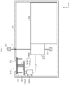
- FIG. 1 is a perspective view schematically showing a battery pack according to an embodiment of the present disclosure.
- FIG. 2 is a diagram schematically showing the inner parts of the battery pack according to an embodiment of the present disclosure.
- FIG. 3 is a partial enlarged diagram schematically showing some of the inner parts of the battery pack according to an embodiment of the present disclosure.
- the X axis direction is the right direction
- the Y axis direction is the rear direction
- the Z axis direction is the up direction.
- the battery pack 100 includes at least one battery module 110, a pack case 120, a control unit 130 and a ventilation unit 140.
- the battery module 110 may include a plurality of battery cells (not shown) and a module case accommodating the plurality of battery cells (not shown).
- the battery cells may include, for example, pouch-type battery cells that have high energy density and are easy to stack.
- the pouch-type battery cells may be stacked to form a battery cell group.
- the battery cells may have electrode leads at left and right ends.
- the battery cells of the present disclosure are not limited to the pouch-type battery cells, and prismatic battery cells of rectangular prism shape or cylindrical battery cells may be used.
- the plurality of battery cells may be electrically connected by a busbar including an electrically conductive metal.
- the busbar may have a metal rod or metal plate shape.
- the busbar may include any known common connection member configured to electrically connect the plurality of battery cells. Its description is omitted.
- the module housing is the component used to receive the plurality of battery cells (not shown), and may be formed with a hermetic structure using a material having high mechanical strength to protect the plurality of battery cells from external physical and chemical factors.
- the module housing of the battery module 110 may be coupled to the pack case 120 by bolting and/or welding.
- the pack case 120 may be configured to accommodate the at least one battery module 110 therein.
- the pack case 120 may be formed with a hermetic structure using a material having high mechanical strength to protect the battery module 110 and the control unit 130 from external physical and chemical factors.
- the pack case 120 may have at least one air hole 121 to allow air to flow in and out.
- the pack case 120 may have one air hole 121 on top of the pack case 120 to allow air to flow in and out.
- the opening shape of the air hole 121 is not limited to a particular shape, but may be, for example, a circular or square shape.
- control unit 130 may be configured to determine whether to open or close the air hole 121 according to a temperature difference between the inside and the outside of the pack case 120. For example, when the temperature difference between the inside and the outside of the pack case 120 is equal to or larger than 15°C, the control unit 130 may be configured to transmit a control signal to the ventilation unit 140 to enable the ventilation unit 140 to open the air hole 121.
- the range of the temperature difference is not necessarily limited to 15°C or above, and the internal and external environmental factors (for example, temperature, humidity) of the battery pack 100 may be considered when determining whether to open or close the air hole 121.
- the control unit 130 may include a memory chip to store the collected temperature information.
- the control unit 130 may include a microcontroller to determine whether to open or close the air hole 121 according to the size of the temperature difference.
- the control unit 130 may include a communication unit to transmit the control signal to the ventilation unit 140.
- the communication unit may perform wireless communication or wired communication using a communication line L.
- the ventilation unit 140 may be configured to directly close the air hole 121 in response to the control signal from the control unit 130.
- the ventilation unit 140 may be configured to directly open the air hole 121 in response to the control signal from the control unit 130.
- the method for closing the air hole 121 is not limited to a particular method, and may include any method for closing the air hole 121.
- the present disclosure since the present disclosure includes the control unit 130 to determine whether to open or close the air hole 121 according to the temperature difference between the inside and the outside of the pack case 120; and the ventilation unit 140 to open or close the air hole 121 in response to the control signal from the control unit 130, when condensation occurs, i.e., water vapor in air inside of the pack case 120 condenses into water due to the temperature difference between the inside and the outside of the pack case 120, it is possible to dry out the produced water by opening the air hole 121 to ventilate the pack case 120 through the control of the control unit 130 and the operation of the ventilation unit 140. Accordingly, the present disclosure may prevent the contact between electrical wires or an electrical short from occurring in the battery module 110, the battery cell and the electrical component in the battery pack 100 due to the produced moisture (water) in the pack case 120.
- the battery pack 100 of the present disclosure may allow outdoor air to flow in through the air hole 121 of the pack case 120 and air inside of the pack case 120 to flow out through the air hole 121, thereby reducing the temperature difference between the inside and the outside of the pack case 120, and thus preventing any further condensation from occurring in the pack case 120.
- the ventilation unit 140 of the battery pack 100 of the present disclosure may include a packing member 141 and a transport member 142.
- the packing member 141 may be configured to close the air hole 121.
- the size of the packing member 141 may be equal to or larger than the size of the air hole 121.
- the material of the packing member 141 may include synthetic rubber or natural rubber.
- the packing member 141 may be ethylene propylene rubber.
- the packing member 141 may have a disc shape having a predetermined thickness.
- the shape of the packing member 141 is not limited to a particular shape, and the shape of the packing member 141 may be set according to the shape of the air hole 121. That is, the packing member 141 may have any shape that closes (covers) the air hole 121.
- the transport member 142 may be configured to operate in response to the control signal from the control unit 130.
- the transport member 142 may receive the control signal from the control unit 130 to transport the packing member 141 toward the air hole 121.
- the transport member 142 may receive the control signal from the control unit 130 to transport the packing member 141 in a direction facing away from the air hole 121. That is, the packing member 141 may be transported by the transport member 142 to bring it into close contact with the air hole 121 or move it away from the air hole 121.
- the transport member 142 may include a receiver to receive a communication signal from the control unit 130.
- the present disclosure since the present disclosure includes the ventilation unit 140 including the packing member 141 and the transport member 142, the air hole 121 of the pack case 120 may be opened or closed according to the temperature difference between the inside and the outside of the pack case 120. Accordingly, when the ventilation unit 140 opens the air hole 121, the battery pack 100 of the present disclosure may allow outdoor air to flow in through the air hole 121 of the pack case 120 and air inside of the pack case 120 to flow out through the air hole 121, thereby reducing the temperature difference between the inside and the outside of the pack case 120, and thus preventing any further condensation from occurring in the pack case 120.
- the transport member 142 of the ventilation unit 140 of the battery pack 100 of the present disclosure may include an electric motor 142a and a transport gear 142b.
- the electric motor 142a may be configured to operate in response to the control signal (an electrical signal) from the control unit 130.
- the electric motor 142a may be a servo motor that operates according to the control signal of the control unit 130.
- the electric motor 142a may have a rotating shaft configured to make rotational movement when power is supplied.
- the transport gear 142b may be configured to transport the packing member 141 toward the air hole 121 by a rotational force transmitted from the electric motor 142a.
- the transport gear 142b may be configured to transport the packing member 141 in the direction facing away from the air hole 121 by the rotational force transmitted from the electric motor 142a.
- the transport gear 142b may transport the packing member 141 toward the air hole 121.
- the transport gear 142b may transport the packing member 141 in the direction facing away from the air hole 121.
- the present disclosure since the present disclosure includes the electric motor 142a and the transport gear 142b, it is easy to control the opening/closing of the air hole 121 according to the electrical signal from the control unit 130.
- a first toothed wheel 142a1 may be at the rotating shaft of the electric motor 142a.
- the first toothed wheel 142a1 may have a disc shape.
- the first toothed wheel 142a1 may rotate in the clockwise direction or the counterclockwise direction by the rotation of the rotating shaft.
- the transport gear 142b may include a body 142b2 extended in a direction.
- the body 142b2 may have a screw thread on the outer surface.
- the screw thread may be a male thread.
- a second toothed wheel 142b 1 may be at one end of the body 142b2.
- the second toothed wheel 142b 1 may engaged with the first toothed wheel 142a1.
- the first toothed wheel 142a1 rotates in the clockwise direction
- the second toothed wheel 142b1 may rotate in the counterclockwise direction.
- the second toothed wheel 142b 1 may rotate in the clockwise direction.
- the transport gear 142b may only allow a rotational motion, and the position of the transport gear 142b may be fixed.
- the transport gear 142b may include a fixing member including a ring around the outer surface of the body 142b2. The ring may be configured to allow the rotational movement of the transport gear 142b and limit the movement of the position of the transport gear 142b.
- the packing member 141 may have a screw hole 141h into which the body 142b2 is inserted.
- the screw hole 141h may have a screw thread on the inner surface.
- the screw thread may be a female thread.
- the packing member 141 may move to the air hole 121 along the outer surface of the body 142b2 of the transport gear 142b.
- the packing member 141 may move in the direction facing away from the air hole 121 along the screw thread on the outer surface of the body 142b2 of the transport gear 142b.
- the present disclosure is not necessarily limited to this method, and the transportation direction may change depending on the type of the screw, for example, a right screw or a left screw.
- the ventilation unit 140 may further include the fixing member 143 to fix part of the packing member 141.
- the fixing member 143 may be configured to prohibit the rotational movement of the packing member 141.
- the fixing member 143 may include two fixing pins. Each of the two fixing pins may be, at one end, fixed to the pack case 120. Each of the two fixing pins may be configured to pass through the packing member 141. That is, the packing member 141 may be configured to move up and down along the outer surface of the fixing pin.
- the packing member 141 when the packing member 141 is transported toward the air hole 121 along the screw thread of the body 142b2 of the transport gear 142b, the packing member 141 may be moved to the air hole 121 along the outer surface of the two fixing pins.
- the packing member 141 when the packing member 141 is transported in the direction facing away from the air hole 121 by the transport gear 142b, the packing member 141 may be moved away from the air hole 121 along the outer surface of the two fixing pins. That is, the two fixing pins may be configured to allow the packing member 141 to move in two directions, but prohibit the packing member 141 from making rotational movement when the packing member 141 receives the rotational force from the transport gear 142b.
- the fixing member 143 is not necessarily limited to this configuration, and may include any fixing member configured to prohibit the packing member 141 from making rotational movement but allow the packing member 141 to move closer to the air hole 121 or away from the air hole 121.
- the present disclosure since the present disclosure includes the first toothed wheel 142a1 at the rotating shaft of the electric motor 142a, the transport gear 142b including the body 142b2 extended in a direction and having the screw thread on the outer surface, and the second toothed wheel 142b1 engaged with the first toothed wheel 142a1 at one end of the body 142b2, the packing member 141 having the screw hole 141h into which the body 142b2 is inserted and having the screw thread on the inner surface, and the ventilation unit 140 further including the fixing member 143 to fix part of the packing member 141 to prohibit the packing member 141 from making rotational movement, it is possible to precisely transport the packing member 141 using the transport member 142.
- the present disclosure may precisely control the opening/closing of the air hole 121 of the pack case 120, and reduce malfunctions. Ultimately, the present disclosure may effectively prevent the contact between electrical wires or an electrical short from occurring in the battery module 110, the battery cell and the electrical component within the battery pack 100 due to condensation in the battery pack 100.
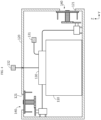
- FIG. 4 is a diagram schematically showing the inner parts of a battery pack according to another embodiment of the present disclosure.
- the battery pack 100 may have two air holes 121 of the pack case 120. Additionally, as opposed to the battery pack 100 of FIG. 2 , the battery pack 100 may include two ventilation units 140. The components of the battery pack 100 of FIG. 4 may be the same as those of the battery pack 100 of FIG. 2 , only different in position.
- the battery pack 100 may have the two air holes 121 at the top and the rear end of the pack case 120, respectively.
- the two ventilation units 140 may close each of the two air holes 121 in response to the control signal from the control unit 130.
- the two ventilation units 140 may be configured to open each of the two air holes 121 in response to the control signal from the control unit 130.
- any one of the two air holes 121 may be configured to allow air outside of the pack case 120 to flow in.
- the remaining air hole 121 may act as a passage through which air inside of the pack case 120 flows out.
- the battery pack 100 of the present disclosure since the battery pack 100 of the present disclosure includes the two air holes 121 and the two ventilation units 140 to open or close each of the two air holes 121, it is possible to allow air to flow into and out of the pack case 120 more smoothly. Accordingly, the battery pack 100 of the present disclosure may ventilate the pack case 120 faster, thereby allowing moisture produced by condensation out fast or preventing condensation from progressing.
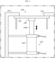
- FIGS. 5 and 6 are diagrams schematically showing some of the inner parts of a battery pack according to still another embodiment of the present disclosure.
- the battery pack 100 may include a cylinder 144 and a packing fixing portion 145 as the transport member 142. That is, the battery pack 100 of FIG. 5 does not include the electric motor 142a and the transport gear 142b of the battery pack 100 of FIG. 2 .
- the remaining components of the battery pack 100 according to still another embodiment of the present disclosure may be the same as those of the battery pack 100 of FIG. 2 .
- the cylinder 144 may be configured to push a shaft outwards according to the control signal from the control unit 130.
- the cylinder 144 may be configured to pull the shaft inwards according to the control signal from the control unit 130. That is, when the temperature difference between the inside and the outside of the pack case 120 is equal to or larger than the predetermined level, the control unit 130 may be configured to transmit the control signal to the ventilation unit 140 to enable the cylinder 144 pull the shaft inwards.
- the packing member 141 may be transported in the direction facing away from the air hole 121.
- control unit 130 may transmit the control signal to the ventilation unit 140 to enable the cylinder 144 to push the shaft outwards.
- the packing member 141 may be transported toward the air hole 121 to close the air hole 121.
- the packing fixing portion 145 may be at the end of the shaft of the cylinder 144.
- the packing fixing portion 145 may be configured to fix the packing member 141.
- the end of the packing fixing portion 145 may be fixed to one side of the packing member 141.
- the end of the packing fixing portion 145 may be attached to the packing member 141 using an adhesive. That is, the packing member 141 attached to the packing fixing portion 145 at the end of the shaft of the cylinder 144 may be transported by the movement of the shaft of the cylinder 144.
- the transport member 142 of the battery pack 100 of the present disclosure since the transport member 142 of the battery pack 100 of the present disclosure includes the cylinder 144 and the packing fixing portion 145, it is possible to effectively control the opening/closing of the air hole 121 of the pack case 120 by the control of the ventilation unit 140 by the control unit 130. Accordingly, the present disclosure may precisely control the opening/closing of the air hole 121 of the pack case 120, and reduce malfunctions. Ultimately, the present disclosure may effectively prevent the contact between electrical wires or an electrical short from occurring in the battery module 110, the battery cell and the electrical component within the battery pack 100 due to condensation in the battery pack 100.
- the battery pack 100 may include an internal temperature sensor 131 and an external temperature sensor 132.
- the internal temperature sensor 131 may be a sensor to detect the temperature of air inside of the pack case 120.
- the internal temperature sensor 131 may be disposed in the pack case 120.
- the internal temperature sensor 131 may have a resistance of a predetermined value according to the detected temperature.
- the control unit 130 may read the predetermined resistance value of the internal temperature sensor 131 through an electrical wire in which electric current flows.
- the internal temperature sensor 131 may be a resistance temperature sensor.
- the external temperature sensor 132 may be configured to detect the temperature of air outside of the pack case 120.
- the external temperature sensor 132 may be disposed outside of the pack case 120.
- the external temperature sensor 132 may have a resistance of a predetermined value according to the detected temperature.
- the control unit 130 may read the predetermined resistance value of the external temperature sensor 132 through an electrical wire in which electric current flows.
- the external temperature sensor 132 may be a resistance temperature sensor.
- the electrical wire may electrically connect the external temperature sensor 132 to the control unit 130 through a small hole of the pack case 120.
- the control unit 130 may be configured to transmit a first control signal to the ventilation unit 140 to enable the ventilation unit 140 to open the air hole 121.
- the control unit 130 may be configured to transmit the first control signal to the ventilation unit 140 to open the air hole 121.
- the range of the temperature difference is not necessarily limited to 15°C or above, and the internal and external environmental factors (for example, temperature, humidity) of the battery pack 100 may be considered when determining whether to open or close the air hole 121.
- the control unit 130 may be configured to transmit a second control signal to enable the ventilation unit 140 to close the air hole 121. For example, 10 minutes after transmitting the first control signal to enable the ventilation unit 140 to open the air hole 121, the control unit 130 may transmit the second control signal to the ventilation unit 140 again to enable the ventilation unit 140 to close the air hole 121. That is, the control unit 130 may perform control to close the air hole 121 to prevent outdoor air from entering the pack case 120 during normal operation. However, when the temperature difference between the inside and the outside of the pack case 120 is equal to or larger than the predetermined level, the control unit 130 may determine that condensation occurred, and transmit the control signal to the ventilation unit 140 to open the air hole 121.
- the period of time during which the ventilation unit 140 keeps the air hole 121 open may change depending on the size of the temperature difference between the inside and the outside of the pack case 120.
- the control unit 130 may perform control to keep the air hole 121 open for a longer time as the temperature difference between the inside and the outside of the pack case 120 is larger.
- the control unit 130 of the battery pack 100 of the present disclosure since the control unit 130 of the battery pack 100 of the present disclosure is configured to transmit the first control signal to enable the ventilation unit 140 to open the air hole 121, and after the predetermined time, transmit the second control signal to enable the ventilation unit 140 to close the air hole 121, the control unit 130 may properly control the period of time during which the air hole 121 of the pack case 120 is open, thereby effectively releasing moisture produced by condensation from the pack case 120. Additionally, the present disclosure may properly reduce the temperature difference between the inside and the outside of the pack case 120.
- FIG. 7 is a diagram schematically showing the inner parts of a battery pack according to yet another embodiment of the present disclosure.
- the battery pack 100 when compared with the battery pack 100 of FIG. 2 , may further include a fan 150.
- the remaining components of the battery pack 100 of FIG. 7 may be the same as those of the battery pack 100 of FIG. 2 .
- the fan 150 may be configured to transport air inside of the pack case 120.
- the fan 150 may blow air inside of the pack case 120 to allow the air to circulate. That is, the fan 150 may minimize the dead space in which air inside of the pack case 120 does not circulate.
- the control unit 130 may be configured to allow the fan 150 to blow air inside of the pack case 120. That is, when the control unit 130 controls the ventilation unit 140 to open the air hole 121, the control unit 130 may operate the fan 150 to circulate air inside of the pack case 120. In this instance, air inside of the pack case 120 containing moisture may exit the air hole 121.
- the present disclosure further includes the fan 150, it is possible to effectively remove moisture at the corners (the edges) of the pack case 120. Additionally, it is possible to release moisture into the atmosphere through the air hole 121 quickly by accelerating the flow rate of air in the pack case 120. Additionally, the fan 150 may force water vapor out through the air hole 121 after converting the water droplets in the pack case 120 produced by condensation to the water vapor fast (evaporation).
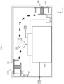
- FIG. 8 is a diagram schematically showing the inner parts of the battery pack 100 according to a further another embodiment of the present disclosure.
- the battery pack 100 when compared with the battery pack 100 of FIG. 7 , may have two air holes 121 in the pack case 120.
- the remaining components of the battery pack 100 of FIG. 8 are similar to those of the battery pack 100 of FIG. 7 , only different in positional characteristics and size.
- the pack case 120 may have at least two air holes 121.
- the fan 150 may be configured to transport air inside of the pack case 120 to force the air out through any one of the at least two air holes 121.
- the battery pack 100 of the present disclosure may have the air holes 121 at the top and the rear end of the pack case 120, respectively.
- the fan 150 may blow air inside of the pack case 120 to force the air out through the air hole 121 at the rear end among the two air holes 121.
- the present disclosure since the present disclosure includes the fan 150 configured to transport air inside of the pack case 120 to force the air out through any one of the at least two air holes 121, one air hole 121 may be configured to allow the flow of air from the outside to the inside of the pack case 120 and the other air hole 121 may be configured to allow the flow of air from the inside to the outside of the pack case 120, thereby removing moisture in the pack case 120 quickly and reducing the temperature difference between the inside and the outside of the pack case 120 quickly. Accordingly, the battery pack 100 of the present disclosure may remove moisture produced by condensation in the battery pack 100, thereby preventing an internal short circuit or the contact between electrical wires in the battery module 110 due to the moisture. Additionally, the battery pack 100 of the present disclosure may prevent the temperature difference between the inside and the outside of the pack case 120 from increasing to above the predetermined level, thereby preventing condensation.
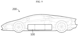
- FIG. 9 is a perspective view schematically showing a vehicle according to an embodiment of the present disclosure.
- the vehicle 200 may include at least one battery pack 100.
- the vehicle may include, for example, a vehicle body in which the battery pack 100 including at least one battery module (not shown) is mounted.
- the vehicle may be an electric vehicle, an electric scooter, an electric wheelchair or an electric bike.
Landscapes
- Chemical & Material Sciences (AREA)
- Chemical Kinetics & Catalysis (AREA)
- Electrochemistry (AREA)
- General Chemical & Material Sciences (AREA)
- Engineering & Computer Science (AREA)
- Manufacturing & Machinery (AREA)
- Aviation & Aerospace Engineering (AREA)
- Automation & Control Theory (AREA)
- Battery Mounting, Suspending (AREA)
- Gas Exhaust Devices For Batteries (AREA)
- Secondary Cells (AREA)
Abstract
Description
- The present disclosure relates to a battery pack and a vehicle comprising the same, and more particularly, to a battery pack for preventing condensation due to a temperature difference between the inside and the outside of a pack case and a vehicle comprising the same.
- The present application claims priority to
Korean Patent Application No. 10-2021-0068645 filed on May 27, 2021 - Recently, there has been a rapid increase in the demand for portable electronic products such as laptop computers, video cameras and mobile phones, and with the extensive development of electric vehicles, accumulators for energy storage, robots and satellites, many studies are being made on high performance secondary batteries that can be repeatedly recharged.
- Currently, commercially available secondary batteries include nickel-cadmium batteries, nickel-hydrogen batteries, nickel-zinc batteries, lithium secondary batteries and the like, and among them, lithium secondary batteries have little or no memory effect, and thus they are gaining more attention than nickel-based secondary batteries for their advantages that recharging can be done whenever it is convenient, the self-discharge rate is very low and the energy density is high.
- The lithium secondary battery usually uses a lithium-based oxide and a carbon material for a positive electrode active material and a negative electrode active material, respectively. Additionally, the lithium secondary battery includes an electrode assembly including a positive electrode plate and a negative electrode plate coated with the positive electrode active material and the negative electrode active material, respectively, with a separator interposed between the positive electrode plate and the negative electrode plate, and a packaging or a battery case in which the electrode assembly is hermetically received together with an electrolyte solution.
- The lithium secondary batteries may be classified into can-type and pouch-type according to the shape of the battery case. The can-type secondary battery includes a metal can accommodating the electrode assembly, and the pouch-type secondary battery includes a pouch of an aluminum laminate sheet accommodating the electrode assembly.
- More recently, there is a growing demand for high capacity battery packs used in electric vehicles. The high capacity battery pack includes a plurality of battery modules, each including secondary battery cells. The high capacity battery pack mounted in electric vehicles may have an increase in temperature difference between the inside and the outside of the battery packs depending on the outdoor environment in which the vehicle drives. When the temperature difference between the inside and the outside of the battery pack is equal to or larger than 15°C, moisture contained in air inside of the battery pack condenses to produce water droplets on the walls of the pack case. The water droplets flow down and stay in the pack case. Due to the produced water in the pack case, an electrical short occurs between the plurality of battery modules, causing thermal runaway of the battery module or electrical fires when electrical wires come in contact with each other between electrical components in the battery pack.
- Accordingly, there is a need for an approach to minimize the electrical short or the contact between electrical wires in the battery pack due to the condensation inside the battery pack.
- The present disclosure is designed to solve the above-described problem, and therefore the present disclosure is directed to providing a battery pack for preventing condensation due to a temperature difference between the inside and the outside of a pack case and a vehicle comprising the same.
- These and other objectives and advantages of the present disclosure can be understood by the following description, and will be apparent from the embodiments of the present disclosure. In addition, it will be readily appreciated that the objectives and advantages of the present disclosure can be realized by the means set forth in the appended claims and a combination thereof.
- To solve the above-described technical problem, a battery pack according to the present disclosure includes at least one battery module; a pack case accommodating the at least one battery module, the pack case having at least one air hole to allow air to flow in and out; a control unit configured to determine whether to open or close the air hole according to a temperature difference between inside and outside of the pack case; and a ventilation unit configured to open or close the air hole in response to a control signal from the control unit.
- The ventilation unit may include a packing member having a size that is equal to or larger than the air hole to close the air hole; and a transport member configured to transport the packing member toward or away from the air hole in response to the control signal from the control unit.
- The transport member may include an electric motor configured to operate in response to the control signal from the control unit; and a transport gear configured to transport the packing member toward or away from the air hole by a rotational force transmitted from the electric motor.
- A first toothed wheel may be at a rotating shaft of the electric motor, the transport gear may include a body extended in a direction and having a screw thread on an outer surface, and a second toothed wheel at an end of the body, the second toothed wheel engaged with the first toothed wheel, the packing member may have a screw hole into which the body is inserted, the screw hole having a screw thread on an inner surface, and the ventilation unit may further include a fixing member to fix part of the packing member to prohibit the packing member from making a rotational movement.
- The transport member may include a cylinder configured to push a shaft outwards or pull the shaft inwards in response to the control signal from the control unit; and a packing fixing portion at an end of the shaft of the cylinder to fix the packing member.
- The battery pack may further include an internal temperature sensor to detect an internal temperature of the pack case; and an external temperature sensor to detect a temperature of air outside of the pack case, and the control unit may be configured to transmit a first control signal to the ventilation unit to enable the ventilation unit to open the air hole when a difference between the internal temperature of the pack case measured by the internal temperature sensor and the external temperature of the pack case measured by the external temperature sensor is equal to or larger than a predetermined level.
- The control unit may be configured to transmit the first control signal to the ventilation unit to enable the ventilation unit to open the air hole, and after a predetermined time, transmit a second control signal to enable the ventilation unit to close the air hole.
- The battery pack may further include a fan configured to transport air inside of the pack case.
- The pack case may have at least two air holes, and the fan may be configured to transport the air inside of the pack case to force the air out through any one of the at least two air holes.
- According to another aspect of the present disclosure, there is provided a vehicle including the battery pack.
- According to an aspect of the present disclosure, since the present disclosure includes the control unit to determine whether to open or close the air hole according to the temperature difference between the inside and the outside of the pack case; and the ventilation unit to open or close the air hole in response to the control signal from the control unit, when condensation occurs, i.e., water vapor in air inside of the pack case condenses into water due to the temperature difference between the inside and the outside of the pack case, it is possible to dry out the produced water by opening the air hole to ventilate the pack case through the control of the control unit and the operation of the ventilation unit.
- Accordingly, the present disclosure may prevent the contact between electrical wires or an electrical short from occurring in the battery module, the battery cell and the electrical component within the battery pack due to the produced moisture in the pack case.
-
-
FIG. 1 is a perspective view schematically showing a battery pack according to an embodiment of the present disclosure. -
FIG. 2 is a diagram schematically showing the inner parts of a battery pack according to an embodiment of the present disclosure. -
FIG. 3 is a partial enlarged diagram schematically showing some of the inner parts of a battery pack according to an embodiment of the present disclosure. -
FIG. 4 is a diagram schematically showing the inner parts of a battery pack according to another embodiment of the present disclosure. -
FIGS. 5 and6 are diagrams schematically showing some of the inner parts of a battery pack according to still another embodiment of the present disclosure. -
FIG. 7 is a diagram schematically showing the inner parts of a battery pack according to yet another embodiment of the present disclosure. -
FIG. 8 is a diagram schematically showing the inner parts of a battery pack according to a further another embodiment of the present disclosure. -
FIG. 9 is a perspective view schematically showing a vehicle according to an embodiment of the present disclosure. - Hereinafter, the exemplary embodiment of the present disclosure will be described in detail with reference to the accompanying drawings. Prior to the description, it should be understood that the terms or words used in the specification and the appended claims should not be construed as being limited to general and dictionary meanings, but rather interpreted based on the meanings and concepts corresponding to the technical aspects of the present disclosure on the basis of the principle that the inventor is allowed to define the terms appropriately for the best explanation.
- Therefore, the embodiments described herein and the illustrations shown in the drawings are just an exemplary embodiment of the present disclosure, but not intended to fully describe the technical aspects of the present disclosure, so it should be understood that a variety of other equivalents and modifications could have been made thereto at the time that the application was filed.
-
FIG. 1 is a perspective view schematically showing a battery pack according to an embodiment of the present disclosure.FIG. 2 is a diagram schematically showing the inner parts of the battery pack according to an embodiment of the present disclosure. Additionally,FIG. 3 is a partial enlarged diagram schematically showing some of the inner parts of the battery pack according to an embodiment of the present disclosure. For reference, inFIG. 1 , the X axis direction is the right direction, the Y axis direction is the rear direction and the Z axis direction is the up direction. - Referring to
FIGS. 1 to 3 , thebattery pack 100 according to an embodiment of the present disclosure includes at least onebattery module 110, apack case 120, acontrol unit 130 and aventilation unit 140. - Specifically, the
battery module 110 may include a plurality of battery cells (not shown) and a module case accommodating the plurality of battery cells (not shown). - Here, the battery cells may include, for example, pouch-type battery cells that have high energy density and are easy to stack. The pouch-type battery cells may be stacked to form a battery cell group. The battery cells may have electrode leads at left and right ends. However, as opposed to this embodiment, the battery cells of the present disclosure are not limited to the pouch-type battery cells, and prismatic battery cells of rectangular prism shape or cylindrical battery cells may be used.
- Although not shown in the drawings, the plurality of battery cells may be electrically connected by a busbar including an electrically conductive metal. The busbar may have a metal rod or metal plate shape. The busbar may include any known common connection member configured to electrically connect the plurality of battery cells. Its description is omitted.
- Furthermore, the module housing is the component used to receive the plurality of battery cells (not shown), and may be formed with a hermetic structure using a material having high mechanical strength to protect the plurality of battery cells from external physical and chemical factors. For example, the module housing of the
battery module 110 may be coupled to thepack case 120 by bolting and/or welding. - Additionally, the
pack case 120 may be configured to accommodate the at least onebattery module 110 therein. Thepack case 120 may be formed with a hermetic structure using a material having high mechanical strength to protect thebattery module 110 and thecontrol unit 130 from external physical and chemical factors. Thepack case 120 may have at least oneair hole 121 to allow air to flow in and out. For example, as shown inFIGS. 1 and2 , thepack case 120 may have oneair hole 121 on top of thepack case 120 to allow air to flow in and out. The opening shape of theair hole 121 is not limited to a particular shape, but may be, for example, a circular or square shape. - Further, the
control unit 130 may be configured to determine whether to open or close theair hole 121 according to a temperature difference between the inside and the outside of thepack case 120. For example, when the temperature difference between the inside and the outside of thepack case 120 is equal to or larger than 15°C, thecontrol unit 130 may be configured to transmit a control signal to theventilation unit 140 to enable theventilation unit 140 to open theair hole 121. However, the range of the temperature difference is not necessarily limited to 15°C or above, and the internal and external environmental factors (for example, temperature, humidity) of thebattery pack 100 may be considered when determining whether to open or close theair hole 121. Thecontrol unit 130 may include a memory chip to store the collected temperature information. Thecontrol unit 130 may include a microcontroller to determine whether to open or close theair hole 121 according to the size of the temperature difference. Thecontrol unit 130 may include a communication unit to transmit the control signal to theventilation unit 140. The communication unit may perform wireless communication or wired communication using a communication line L. - Additionally, the
ventilation unit 140 may be configured to directly close theair hole 121 in response to the control signal from thecontrol unit 130. Theventilation unit 140 may be configured to directly open theair hole 121 in response to the control signal from thecontrol unit 130. The method for closing theair hole 121 is not limited to a particular method, and may include any method for closing theair hole 121. - According to this configuration of the present disclosure, since the present disclosure includes the
control unit 130 to determine whether to open or close theair hole 121 according to the temperature difference between the inside and the outside of thepack case 120; and theventilation unit 140 to open or close theair hole 121 in response to the control signal from thecontrol unit 130, when condensation occurs, i.e., water vapor in air inside of thepack case 120 condenses into water due to the temperature difference between the inside and the outside of thepack case 120, it is possible to dry out the produced water by opening theair hole 121 to ventilate thepack case 120 through the control of thecontrol unit 130 and the operation of theventilation unit 140. Accordingly, the present disclosure may prevent the contact between electrical wires or an electrical short from occurring in thebattery module 110, the battery cell and the electrical component in thebattery pack 100 due to the produced moisture (water) in thepack case 120. - Furthermore, when the
ventilation unit 140 opens theair hole 121, thebattery pack 100 of the present disclosure may allow outdoor air to flow in through theair hole 121 of thepack case 120 and air inside of thepack case 120 to flow out through theair hole 121, thereby reducing the temperature difference between the inside and the outside of thepack case 120, and thus preventing any further condensation from occurring in thepack case 120. - Referring back to
FIGS. 1 to 3 , theventilation unit 140 of thebattery pack 100 of the present disclosure may include a packingmember 141 and atransport member 142. The packingmember 141 may be configured to close theair hole 121. The size of the packingmember 141 may be equal to or larger than the size of theair hole 121. The material of the packingmember 141 may include synthetic rubber or natural rubber. For example, the packingmember 141 may be ethylene propylene rubber. When theair hole 121 is, for example, circular, the packingmember 141 may have a disc shape having a predetermined thickness. However, the shape of the packingmember 141 is not limited to a particular shape, and the shape of the packingmember 141 may be set according to the shape of theair hole 121. That is, the packingmember 141 may have any shape that closes (covers) theair hole 121. - Additionally, the
transport member 142 may be configured to operate in response to the control signal from thecontrol unit 130. Thetransport member 142 may receive the control signal from thecontrol unit 130 to transport the packingmember 141 toward theair hole 121. Thetransport member 142 may receive the control signal from thecontrol unit 130 to transport the packingmember 141 in a direction facing away from theair hole 121. That is, the packingmember 141 may be transported by thetransport member 142 to bring it into close contact with theair hole 121 or move it away from theair hole 121. For example, thetransport member 142 may include a receiver to receive a communication signal from thecontrol unit 130. - According to this configuration of the present disclosure, since the present disclosure includes the
ventilation unit 140 including the packingmember 141 and thetransport member 142, theair hole 121 of thepack case 120 may be opened or closed according to the temperature difference between the inside and the outside of thepack case 120. Accordingly, when theventilation unit 140 opens theair hole 121, thebattery pack 100 of the present disclosure may allow outdoor air to flow in through theair hole 121 of thepack case 120 and air inside of thepack case 120 to flow out through theair hole 121, thereby reducing the temperature difference between the inside and the outside of thepack case 120, and thus preventing any further condensation from occurring in thepack case 120. - Referring back to
FIGS. 1 to 3 , thetransport member 142 of theventilation unit 140 of thebattery pack 100 of the present disclosure may include anelectric motor 142a and atransport gear 142b. Theelectric motor 142a may be configured to operate in response to the control signal (an electrical signal) from thecontrol unit 130. For example, theelectric motor 142a may be a servo motor that operates according to the control signal of thecontrol unit 130. Theelectric motor 142a may have a rotating shaft configured to make rotational movement when power is supplied. - Additionally, the
transport gear 142b may be configured to transport the packingmember 141 toward theair hole 121 by a rotational force transmitted from theelectric motor 142a. Thetransport gear 142b may be configured to transport the packingmember 141 in the direction facing away from theair hole 121 by the rotational force transmitted from theelectric motor 142a. For example, when the rotating shaft of theelectric motor 142a rotates in the counterclockwise direction, thetransport gear 142b may transport the packingmember 141 toward theair hole 121. When the rotating shaft of theelectric motor 142a rotates in the clockwise direction, thetransport gear 142b may transport the packingmember 141 in the direction facing away from theair hole 121. - According to this configuration of the present disclosure, since the present disclosure includes the
electric motor 142a and thetransport gear 142b, it is easy to control the opening/closing of theair hole 121 according to the electrical signal from thecontrol unit 130. - Furthermore, a first toothed wheel 142a1 may be at the rotating shaft of the
electric motor 142a. The first toothed wheel 142a1 may have a disc shape. The first toothed wheel 142a1 may rotate in the clockwise direction or the counterclockwise direction by the rotation of the rotating shaft. - Additionally, the
transport gear 142b may include a body 142b2 extended in a direction. The body 142b2 may have a screw thread on the outer surface. The screw thread may be a male thread. A secondtoothed wheel 142b 1 may be at one end of the body 142b2. The secondtoothed wheel 142b 1 may engaged with the first toothed wheel 142a1. For example, when the first toothed wheel 142a1 rotates in the clockwise direction, the second toothed wheel 142b1 may rotate in the counterclockwise direction. On the contrary, when the first toothed wheel 142a1 rotates in the counterclockwise direction, the secondtoothed wheel 142b 1 may rotate in the clockwise direction. Thetransport gear 142b may only allow a rotational motion, and the position of thetransport gear 142b may be fixed. For example, thetransport gear 142b may include a fixing member including a ring around the outer surface of the body 142b2. The ring may be configured to allow the rotational movement of thetransport gear 142b and limit the movement of the position of thetransport gear 142b. - Further, the packing
member 141 may have ascrew hole 141h into which the body 142b2 is inserted. Thescrew hole 141h may have a screw thread on the inner surface. The screw thread may be a female thread. For example, when the body 142b2 of thetransport gear 142b rotates in the counterclockwise direction, the packingmember 141 may move to theair hole 121 along the outer surface of the body 142b2 of thetransport gear 142b. When the body 142b2 of thetransport gear 142b rotates in the clockwise direction, the packingmember 141 may move in the direction facing away from theair hole 121 along the screw thread on the outer surface of the body 142b2 of thetransport gear 142b. However, the present disclosure is not necessarily limited to this method, and the transportation direction may change depending on the type of the screw, for example, a right screw or a left screw. - Additionally, the
ventilation unit 140 may further include the fixingmember 143 to fix part of the packingmember 141. The fixingmember 143 may be configured to prohibit the rotational movement of the packingmember 141. For example, as shown inFIG. 3 , the fixingmember 143 may include two fixing pins. Each of the two fixing pins may be, at one end, fixed to thepack case 120. Each of the two fixing pins may be configured to pass through the packingmember 141. That is, the packingmember 141 may be configured to move up and down along the outer surface of the fixing pin. In other words, when the packingmember 141 is transported toward theair hole 121 along the screw thread of the body 142b2 of thetransport gear 142b, the packingmember 141 may be moved to theair hole 121 along the outer surface of the two fixing pins. On the contrary, when the packingmember 141 is transported in the direction facing away from theair hole 121 by thetransport gear 142b, the packingmember 141 may be moved away from theair hole 121 along the outer surface of the two fixing pins. That is, the two fixing pins may be configured to allow the packingmember 141 to move in two directions, but prohibit the packingmember 141 from making rotational movement when the packingmember 141 receives the rotational force from thetransport gear 142b. Although the fixing pin has been described as an embodiment of the fixingmember 143, the fixingmember 143 is not necessarily limited to this configuration, and may include any fixing member configured to prohibit the packingmember 141 from making rotational movement but allow the packingmember 141 to move closer to theair hole 121 or away from theair hole 121. - According to this configuration of the present disclosure, since the present disclosure includes the first toothed wheel 142a1 at the rotating shaft of the
electric motor 142a, thetransport gear 142b including the body 142b2 extended in a direction and having the screw thread on the outer surface, and the second toothed wheel 142b1 engaged with the first toothed wheel 142a1 at one end of the body 142b2, the packingmember 141 having thescrew hole 141h into which the body 142b2 is inserted and having the screw thread on the inner surface, and theventilation unit 140 further including the fixingmember 143 to fix part of the packingmember 141 to prohibit the packingmember 141 from making rotational movement, it is possible to precisely transport the packingmember 141 using thetransport member 142. Accordingly, the present disclosure may precisely control the opening/closing of theair hole 121 of thepack case 120, and reduce malfunctions. Ultimately, the present disclosure may effectively prevent the contact between electrical wires or an electrical short from occurring in thebattery module 110, the battery cell and the electrical component within thebattery pack 100 due to condensation in thebattery pack 100. -
FIG. 4 is a diagram schematically showing the inner parts of a battery pack according to another embodiment of the present disclosure. - Referring to
FIG. 4 , as opposed to thebattery pack 100 ofFIG. 2 , thebattery pack 100 according to another embodiment of the present disclosure may have twoair holes 121 of thepack case 120. Additionally, as opposed to thebattery pack 100 ofFIG. 2 , thebattery pack 100 may include twoventilation units 140. The components of thebattery pack 100 ofFIG. 4 may be the same as those of thebattery pack 100 ofFIG. 2 , only different in position. - Specifically, the
battery pack 100 according to another embodiment of the present disclosure may have the twoair holes 121 at the top and the rear end of thepack case 120, respectively. The twoventilation units 140 may close each of the twoair holes 121 in response to the control signal from thecontrol unit 130. Alternatively, the twoventilation units 140 may be configured to open each of the twoair holes 121 in response to the control signal from thecontrol unit 130. In this instance, when the twoair holes 121 are opened by theventilation unit 140, any one of the twoair holes 121 may be configured to allow air outside of thepack case 120 to flow in. Additionally, the remainingair hole 121 may act as a passage through which air inside of thepack case 120 flows out. - According to this configuration of the present disclosure, since the
battery pack 100 of the present disclosure includes the twoair holes 121 and the twoventilation units 140 to open or close each of the twoair holes 121, it is possible to allow air to flow into and out of thepack case 120 more smoothly. Accordingly, thebattery pack 100 of the present disclosure may ventilate thepack case 120 faster, thereby allowing moisture produced by condensation out fast or preventing condensation from progressing. -
FIGS. 5 and6 are diagrams schematically showing some of the inner parts of a battery pack according to still another embodiment of the present disclosure. - Referring to
FIGS. 5 and6 , as opposed to thebattery pack 100 ofFIG. 2 , thebattery pack 100 according to still another embodiment of the present disclosure may include acylinder 144 and apacking fixing portion 145 as thetransport member 142. That is, thebattery pack 100 ofFIG. 5 does not include theelectric motor 142a and thetransport gear 142b of thebattery pack 100 ofFIG. 2 . The remaining components of thebattery pack 100 according to still another embodiment of the present disclosure may be the same as those of thebattery pack 100 ofFIG. 2 . - Specifically, the
cylinder 144 may be configured to push a shaft outwards according to the control signal from thecontrol unit 130. Thecylinder 144 may be configured to pull the shaft inwards according to the control signal from thecontrol unit 130. That is, when the temperature difference between the inside and the outside of thepack case 120 is equal to or larger than the predetermined level, thecontrol unit 130 may be configured to transmit the control signal to theventilation unit 140 to enable thecylinder 144 pull the shaft inwards. In this instance, the packingmember 141 may be transported in the direction facing away from theair hole 121. On the contrary, when the temperature difference between the inside and the outside of thepack case 120 is lower than the predetermined level, thecontrol unit 130 may transmit the control signal to theventilation unit 140 to enable thecylinder 144 to push the shaft outwards. In this instance, the packingmember 141 may be transported toward theair hole 121 to close theair hole 121. - Additionally, the
packing fixing portion 145 may be at the end of the shaft of thecylinder 144. Thepacking fixing portion 145 may be configured to fix the packingmember 141. For example, the end of thepacking fixing portion 145 may be fixed to one side of the packingmember 141. The end of thepacking fixing portion 145 may be attached to the packingmember 141 using an adhesive. That is, the packingmember 141 attached to thepacking fixing portion 145 at the end of the shaft of thecylinder 144 may be transported by the movement of the shaft of thecylinder 144. - According to this configuration of the present disclosure, since the
transport member 142 of thebattery pack 100 of the present disclosure includes thecylinder 144 and thepacking fixing portion 145, it is possible to effectively control the opening/closing of theair hole 121 of thepack case 120 by the control of theventilation unit 140 by thecontrol unit 130. Accordingly, the present disclosure may precisely control the opening/closing of theair hole 121 of thepack case 120, and reduce malfunctions. Ultimately, the present disclosure may effectively prevent the contact between electrical wires or an electrical short from occurring in thebattery module 110, the battery cell and the electrical component within thebattery pack 100 due to condensation in thebattery pack 100. - Referring back to
FIG. 2 , thebattery pack 100 according to an embodiment of the present disclosure may include aninternal temperature sensor 131 and anexternal temperature sensor 132. Theinternal temperature sensor 131 may be a sensor to detect the temperature of air inside of thepack case 120. Theinternal temperature sensor 131 may be disposed in thepack case 120. Theinternal temperature sensor 131 may have a resistance of a predetermined value according to the detected temperature. Thecontrol unit 130 may read the predetermined resistance value of theinternal temperature sensor 131 through an electrical wire in which electric current flows. Theinternal temperature sensor 131 may be a resistance temperature sensor. - Additionally, the
external temperature sensor 132 may be configured to detect the temperature of air outside of thepack case 120. Theexternal temperature sensor 132 may be disposed outside of thepack case 120. Theexternal temperature sensor 132 may have a resistance of a predetermined value according to the detected temperature. Thecontrol unit 130 may read the predetermined resistance value of theexternal temperature sensor 132 through an electrical wire in which electric current flows. Theexternal temperature sensor 132 may be a resistance temperature sensor. The electrical wire may electrically connect theexternal temperature sensor 132 to thecontrol unit 130 through a small hole of thepack case 120. - Furthermore, when the difference between the temperature of air inside of the
pack case 120 measured by theinternal temperature sensor 131 and the temperature of air outside of thepack case 120 measured by theexternal temperature sensor 132 is equal to or larger than the predetermined level, thecontrol unit 130 may be configured to transmit a first control signal to theventilation unit 140 to enable theventilation unit 140 to open theair hole 121. For example, when the difference in temperature measured by each of theinternal temperature sensor 131 and theexternal temperature sensor 132 is equal to or larger than 15°C, thecontrol unit 130 may be configured to transmit the first control signal to theventilation unit 140 to open theair hole 121. However, the range of the temperature difference is not necessarily limited to 15°C or above, and the internal and external environmental factors (for example, temperature, humidity) of thebattery pack 100 may be considered when determining whether to open or close theair hole 121. - Additionally, a predetermined time after transmitting the first control signal to enable the
ventilation unit 140 to open theair hole 121, thecontrol unit 130 may be configured to transmit a second control signal to enable theventilation unit 140 to close theair hole 121. For example, 10 minutes after transmitting the first control signal to enable theventilation unit 140 to open theair hole 121, thecontrol unit 130 may transmit the second control signal to theventilation unit 140 again to enable theventilation unit 140 to close theair hole 121. That is, thecontrol unit 130 may perform control to close theair hole 121 to prevent outdoor air from entering thepack case 120 during normal operation. However, when the temperature difference between the inside and the outside of thepack case 120 is equal to or larger than the predetermined level, thecontrol unit 130 may determine that condensation occurred, and transmit the control signal to theventilation unit 140 to open theair hole 121. - Additionally, the period of time during which the
ventilation unit 140 keeps theair hole 121 open may change depending on the size of the temperature difference between the inside and the outside of thepack case 120. For example, thecontrol unit 130 may perform control to keep theair hole 121 open for a longer time as the temperature difference between the inside and the outside of thepack case 120 is larger. - According to this configuration of the present disclosure, since the
control unit 130 of thebattery pack 100 of the present disclosure is configured to transmit the first control signal to enable theventilation unit 140 to open theair hole 121, and after the predetermined time, transmit the second control signal to enable theventilation unit 140 to close theair hole 121, thecontrol unit 130 may properly control the period of time during which theair hole 121 of thepack case 120 is open, thereby effectively releasing moisture produced by condensation from thepack case 120. Additionally, the present disclosure may properly reduce the temperature difference between the inside and the outside of thepack case 120. -
FIG. 7 is a diagram schematically showing the inner parts of a battery pack according to yet another embodiment of the present disclosure. - Referring to
FIG. 7 , when compared with thebattery pack 100 ofFIG. 2 , thebattery pack 100 according to yet another embodiment of the present disclosure may further include afan 150. The remaining components of thebattery pack 100 ofFIG. 7 may be the same as those of thebattery pack 100 ofFIG. 2 . - Specifically, the
fan 150 may be configured to transport air inside of thepack case 120. For example, as shown inFIG 7 , thefan 150 may blow air inside of thepack case 120 to allow the air to circulate. That is, thefan 150 may minimize the dead space in which air inside of thepack case 120 does not circulate. When the temperature difference between the inside and the outside of thepack case 120 is equal to or larger than the predetermined level, thecontrol unit 130 may be configured to allow thefan 150 to blow air inside of thepack case 120. That is, when thecontrol unit 130 controls theventilation unit 140 to open theair hole 121, thecontrol unit 130 may operate thefan 150 to circulate air inside of thepack case 120. In this instance, air inside of thepack case 120 containing moisture may exit theair hole 121. - According to this configuration of the present disclosure, since the present disclosure further includes the
fan 150, it is possible to effectively remove moisture at the corners (the edges) of thepack case 120. Additionally, it is possible to release moisture into the atmosphere through theair hole 121 quickly by accelerating the flow rate of air in thepack case 120. Additionally, thefan 150 may force water vapor out through theair hole 121 after converting the water droplets in thepack case 120 produced by condensation to the water vapor fast (evaporation). -
FIG. 8 is a diagram schematically showing the inner parts of thebattery pack 100 according to a further another embodiment of the present disclosure. - Referring to
FIG. 8 , when compared with thebattery pack 100 ofFIG. 7 , thebattery pack 100 according to a further another embodiment of the present disclosure may have twoair holes 121 in thepack case 120. The remaining components of thebattery pack 100 ofFIG. 8 are similar to those of thebattery pack 100 ofFIG. 7 , only different in positional characteristics and size. - Specifically, the
pack case 120 may have at least twoair holes 121. Thefan 150 may be configured to transport air inside of thepack case 120 to force the air out through any one of the at least twoair holes 121. For example, as shown inFIG 8 , thebattery pack 100 of the present disclosure may have the air holes 121 at the top and the rear end of thepack case 120, respectively. Thefan 150 may blow air inside of thepack case 120 to force the air out through theair hole 121 at the rear end among the twoair holes 121. - According to this configuration of the present disclosure, since the present disclosure includes the
fan 150 configured to transport air inside of thepack case 120 to force the air out through any one of the at least twoair holes 121, oneair hole 121 may be configured to allow the flow of air from the outside to the inside of thepack case 120 and theother air hole 121 may be configured to allow the flow of air from the inside to the outside of thepack case 120, thereby removing moisture in thepack case 120 quickly and reducing the temperature difference between the inside and the outside of thepack case 120 quickly. Accordingly, thebattery pack 100 of the present disclosure may remove moisture produced by condensation in thebattery pack 100, thereby preventing an internal short circuit or the contact between electrical wires in thebattery module 110 due to the moisture. Additionally, thebattery pack 100 of the present disclosure may prevent the temperature difference between the inside and the outside of thepack case 120 from increasing to above the predetermined level, thereby preventing condensation. -
FIG. 9 is a perspective view schematically showing a vehicle according to an embodiment of the present disclosure. - Referring to
FIG. 9 together withFIG. 1 , thevehicle 200 according to an embodiment of the present disclosure may include at least onebattery pack 100. The vehicle may include, for example, a vehicle body in which thebattery pack 100 including at least one battery module (not shown) is mounted. For example, the vehicle may be an electric vehicle, an electric scooter, an electric wheelchair or an electric bike. - Referring to
FIG. 9 together withFIG. 1 , thevehicle 200 according to an embodiment of the present disclosure may include at least onebattery pack 100. The vehicle may include, for example, a vehicle body in which thebattery pack 100 including at least one battery module (not shown) is mounted. For example, the vehicle may be an electric vehicle, an electric scooter, an electric wheelchair or an electric bike. - Meanwhile, the terms indicating directions as used herein such as upper, lower, left, right, front and rear are used for convenience of description only, and it is obvious to those skilled in the art that the term may change depending on the position of the stated element or an observer.
- While the present disclosure has been hereinabove described with regard to a limited number of embodiments and drawings, the present disclosure is not limited thereto and it is obvious to those skilled in the art that various modifications and changes may be made thereto within the technical aspects of the present disclosure and the scope of the appended claims and equivalents thereof.
Claims (10)
- A battery pack, comprising:at least one battery module;a pack case accommodating the at least one battery module, the pack case having at least one air hole to allow air to flow in and out;a control unit configured to determine whether to open or close the air hole according to a temperature difference between inside and outside of the pack case; anda ventilation unit configured to open or close the air hole in response to a control signal from the control unit.
- The battery pack according to claim 1, wherein the ventilation unit includes:a packing member having a size that is equal to or larger than the air hole to close the air hole; anda transport member configured to transport the packing member toward or away from the air hole in response to the control signal from the control unit.
- The battery pack according to claim 2, wherein the transport member includes:an electric motor configured to operate in response to the control signal from the control unit; anda transport gear configured to transport the packing member toward or away from the air hole by a rotational force transmitted from the electric motor.
- The battery pack according to claim 3, wherein a first toothed wheel is at a rotating shaft of the electric motor,wherein the transport gear includes a body extended in a direction and having a screw thread on an outer surface, and a second toothed wheel at an end of the body, the second toothed wheel engaged with the first toothed wheel,wherein the packing member has a screw hole into which the body is inserted, the screw hole having a screw thread on an inner surface, andwherein the ventilation unit further includes a fixing member to fix part of the packing member to prohibit the packing member from making a rotational movement.
- The battery pack according to claim 2, wherein the transport member includes:a cylinder configured to push a shaft outwards or pull the shaft inwards in response to the control signal from the control unit; anda packing fixing portion at an end of the shaft of the cylinder to fix the packing member.
- The battery pack according to claim 1, further comprising:an internal temperature sensor to detect an internal temperature of the pack case; andan external temperature sensor to detect a temperature of air outside of the pack case,wherein the control unit is configured to transmit a first control signal to the ventilation unit to enable the ventilation unit to open the air hole when a difference between the internal temperature of the pack case measured by the internal temperature sensor and the external temperature of the pack case measured by the external temperature sensor is equal to or larger than a predetermined level.
- The battery pack according to claim 6, wherein the control unit is configured to transmit the first control signal to the ventilation unit to enable the ventilation unit to open the air hole, and after a predetermined time, transmit a second control signal to enable the ventilation unit to close the air hole.
- The battery pack according to claim 1, further comprising:
a fan configured to transport air inside of the pack case. - The battery pack according to claim 8, wherein the pack case has at least two air holes, and
wherein the fan is configured to transport the air inside of the pack case to force the air out through any one of the at least two air holes. - A vehicle comprising the battery pack according to any one of claims 1 to 9.
Applications Claiming Priority (2)
| Application Number | Priority Date | Filing Date | Title |
|---|---|---|---|
| KR1020210068645A KR102855958B1 (en) | 2021-05-27 | 2021-05-27 | Battery Pack, and Vehicle Having the Same |
| PCT/KR2022/006840 WO2022250345A1 (en) | 2021-05-27 | 2022-05-12 | Battery pack and vehicle including same |
Publications (3)
| Publication Number | Publication Date |
|---|---|
| EP4199189A1 true EP4199189A1 (en) | 2023-06-21 |
| EP4199189A4 EP4199189A4 (en) | 2024-03-20 |
| EP4199189B1 EP4199189B1 (en) | 2025-11-19 |
Family
ID=84228273
Family Applications (1)
| Application Number | Title | Priority Date | Filing Date |
|---|---|---|---|
| EP22811538.2A Active EP4199189B1 (en) | 2021-05-27 | 2022-05-12 | Battery pack and vehicle comprising the same |
Country Status (7)
| Country | Link |
|---|---|
| US (1) | US20250202037A1 (en) |
| EP (1) | EP4199189B1 (en) |
| JP (1) | JP7684387B2 (en) |
| KR (1) | KR102855958B1 (en) |
| CN (1) | CN116250117B (en) |
| ES (1) | ES3057106T3 (en) |
| WO (1) | WO2022250345A1 (en) |
Families Citing this family (2)
| Publication number | Priority date | Publication date | Assignee | Title |
|---|---|---|---|---|
| EP4550555A4 (en) * | 2022-12-23 | 2025-08-13 | Lg Energy Solution Ltd | BATTERY PACK |
| CN119361910B (en) * | 2024-12-25 | 2025-03-25 | 南京创源动力科技有限公司 | Battery pack and vehicle |
Family Cites Families (18)
| Publication number | Priority date | Publication date | Assignee | Title |
|---|---|---|---|---|
| JPH07298411A (en) * | 1994-04-19 | 1995-11-10 | Toyota Autom Loom Works Ltd | On-board charger for electric vehicles |
| JP3571884B2 (en) * | 1997-09-09 | 2004-09-29 | ダイハツ工業株式会社 | Battery unit cooling device |
| JP3485794B2 (en) * | 1998-03-20 | 2004-01-13 | 日産ディーゼル工業株式会社 | Capacitor cooling device |
| JP4707346B2 (en) * | 2004-08-16 | 2011-06-22 | 三洋電機株式会社 | Power supply for vehicle |
| JP4768277B2 (en) * | 2005-01-28 | 2011-09-07 | プライムアースEvエナジー株式会社 | Cooling device and power supply device |
| JP2010040420A (en) * | 2008-08-07 | 2010-02-18 | Sanyo Electric Co Ltd | Power source device for vehicle |
| DE102009054922A1 (en) * | 2009-12-18 | 2011-06-22 | SB LiMotive Company Ltd., Kyonggi | Method and device for reducing the humidity of a gas in a housing interior |
| JP5455725B2 (en) * | 2010-03-15 | 2014-03-26 | 三菱重工業株式会社 | Assembled battery |
| FR2966288B1 (en) * | 2010-10-19 | 2013-03-29 | Commissariat Energie Atomique | BATTERY OF AN ELECTRIC MOTORIZATION OF A MOTOR VEHICLE |
| KR101317523B1 (en) * | 2010-12-20 | 2013-10-15 | 인지컨트롤스 주식회사 | Battery protection apparatus for a battery car |
| JP5912450B2 (en) * | 2011-11-25 | 2016-04-27 | トヨタ自動車株式会社 | Power storage device, battery temperature control method |
| KR101501544B1 (en) * | 2013-11-13 | 2015-03-12 | 엘아이지넥스원 주식회사 | Hybrid vehicle and method for controlling temperature of secondary battery thereof |
| JP6297922B2 (en) * | 2014-05-23 | 2018-03-20 | 株式会社デンソー | Battery pack |
| JP2016079858A (en) * | 2014-10-15 | 2016-05-16 | 三菱自動車工業株式会社 | Valve structure of intake / exhaust valve of engine |
| KR101786991B1 (en) * | 2015-08-31 | 2017-10-18 | 에스케이이노베이션 주식회사 | Secondary battery module |
| CN208210007U (en) * | 2017-06-01 | 2018-12-07 | 深圳市威誉特通讯设备有限公司 | A kind of automobile batteries case remote monitoring system |
| KR102378374B1 (en) * | 2018-06-18 | 2022-03-25 | 주식회사 엘지에너지솔루션 | Battery Module Having Bus-bar and Battery Pack |
| KR20210068645A (en) | 2019-12-02 | 2021-06-10 | 김태현 | Pocket with bag |
-
2021
- 2021-05-27 KR KR1020210068645A patent/KR102855958B1/en active Active
-
2022
- 2022-05-12 WO PCT/KR2022/006840 patent/WO2022250345A1/en not_active Ceased
- 2022-05-12 JP JP2023514138A patent/JP7684387B2/en active Active
- 2022-05-12 CN CN202280006522.5A patent/CN116250117B/en active Active
- 2022-05-12 US US18/024,117 patent/US20250202037A1/en active Pending
- 2022-05-12 ES ES22811538T patent/ES3057106T3/en active Active
- 2022-05-12 EP EP22811538.2A patent/EP4199189B1/en active Active
Also Published As
| Publication number | Publication date |
|---|---|
| KR20220160422A (en) | 2022-12-06 |
| KR102855958B1 (en) | 2025-09-04 |
| EP4199189A4 (en) | 2024-03-20 |
| US20250202037A1 (en) | 2025-06-19 |
| CN116250117A (en) | 2023-06-09 |
| CN116250117B (en) | 2026-04-21 |
| WO2022250345A1 (en) | 2022-12-01 |
| ES3057106T3 (en) | 2026-02-26 |
| JP2023540287A (en) | 2023-09-22 |
| JP7684387B2 (en) | 2025-05-27 |
| EP4199189B1 (en) | 2025-11-19 |
Similar Documents
| Publication | Publication Date | Title |
|---|---|---|
| US11594776B2 (en) | Battery module including heat shrinkable tube | |
| US10461288B2 (en) | Battery module and battery pack including same | |
| KR102120118B1 (en) | Battery module | |
| CN107431163B (en) | Battery pack and method of making the same | |
| US10243193B2 (en) | Battery pack | |
| US10971778B2 (en) | Battery pack | |
| EP4290665B1 (en) | Battery pack with improved safety | |
| EP4207461A1 (en) | Battery pack and automobile including same | |
| EP4053989A1 (en) | Battery module having busbar, battery pack and vehicle | |
| EP4199189A1 (en) | Battery pack and vehicle including same | |
| KR101806994B1 (en) | Battery module and battery pack including the same | |
| EP3664185B1 (en) | Electrical assembly and battery pack including electrical assembly | |
| Herrmann | Packaging-materials review | |
| US20230025048A1 (en) | Battery cell, battery pack and electronic device | |
| KR101806411B1 (en) | Battery pack having gas shifting pipe | |
| JP2025541788A (en) | Battery cells, batteries and electrical devices | |
| US20240170821A1 (en) | Battery pack and energy storage system including the same | |
| KR20230163703A (en) | Battery module, battery pack and device comprising the same | |
| CN117941151A (en) | Battery pack and device comprising same | |
| KR20230075980A (en) | Battery Cell and apparatus including the same |
Legal Events
| Date | Code | Title | Description |
|---|---|---|---|
| STAA | Information on the status of an ep patent application or granted ep patent |
Free format text: STATUS: THE INTERNATIONAL PUBLICATION HAS BEEN MADE |
|
| PUAI | Public reference made under article 153(3) epc to a published international application that has entered the european phase |
Free format text: ORIGINAL CODE: 0009012 |
|
| STAA | Information on the status of an ep patent application or granted ep patent |
Free format text: STATUS: REQUEST FOR EXAMINATION WAS MADE |
|
| 17P | Request for examination filed |
Effective date: 20230317 |
|
| AK | Designated contracting states |
Kind code of ref document: A1 Designated state(s): AL AT BE BG CH CY CZ DE DK EE ES FI FR GB GR HR HU IE IS IT LI LT LU LV MC MK MT NL NO PL PT RO RS SE SI SK SM TR |
|
| A4 | Supplementary search report drawn up and despatched |
Effective date: 20240216 |
|
| RIC1 | Information provided on ipc code assigned before grant |
Ipc: H01M 50/249 20210101ALI20240212BHEP Ipc: H01M 10/625 20140101ALI20240212BHEP Ipc: H01M 10/6563 20140101ALI20240212BHEP Ipc: H01M 10/6562 20140101ALI20240212BHEP Ipc: H01M 10/635 20140101AFI20240212BHEP |
|
| DAV | Request for validation of the european patent (deleted) | ||
| DAX | Request for extension of the european patent (deleted) | ||
| STAA | Information on the status of an ep patent application or granted ep patent |
Free format text: STATUS: EXAMINATION IS IN PROGRESS |
|
| 17Q | First examination report despatched |
Effective date: 20250116 |
|
| GRAP | Despatch of communication of intention to grant a patent |
Free format text: ORIGINAL CODE: EPIDOSNIGR1 |
|
| STAA | Information on the status of an ep patent application or granted ep patent |
Free format text: STATUS: GRANT OF PATENT IS INTENDED |
|
| RIC1 | Information provided on ipc code assigned before grant |
Ipc: H01M 50/317 20210101ALI20250530BHEP Ipc: H01M 50/204 20210101ALI20250530BHEP Ipc: H01M 10/48 20060101ALI20250530BHEP Ipc: H01M 10/42 20060101ALI20250530BHEP Ipc: H01M 50/375 20210101ALI20250530BHEP Ipc: H01M 10/6562 20140101ALI20250530BHEP Ipc: H01M 10/6563 20140101ALI20250530BHEP Ipc: H01M 10/625 20140101ALI20250530BHEP Ipc: H01M 50/249 20210101ALI20250530BHEP Ipc: H01M 10/635 20140101AFI20250530BHEP |
|
| INTG | Intention to grant announced |
Effective date: 20250623 |
|
| P01 | Opt-out of the competence of the unified patent court (upc) registered |
Free format text: CASE NUMBER: APP_30727/2025 Effective date: 20250626 |
|
| GRAS | Grant fee paid |
Free format text: ORIGINAL CODE: EPIDOSNIGR3 |
|
| GRAA | (expected) grant |
Free format text: ORIGINAL CODE: 0009210 |
|
| STAA | Information on the status of an ep patent application or granted ep patent |
Free format text: STATUS: THE PATENT HAS BEEN GRANTED |
|
| AK | Designated contracting states |
Kind code of ref document: B1 Designated state(s): AL AT BE BG CH CY CZ DE DK EE ES FI FR GB GR HR HU IE IS IT LI LT LU LV MC MK MT NL NO PL PT RO RS SE SI SK SM TR |
|
| REG | Reference to a national code |
Ref country code: CH Ref legal event code: F10 Free format text: ST27 STATUS EVENT CODE: U-0-0-F10-F00 (AS PROVIDED BY THE NATIONAL OFFICE) Effective date: 20251119 Ref country code: GB Ref legal event code: FG4D |
|
| REG | Reference to a national code |
Ref country code: DE Ref legal event code: R096 Ref document number: 602022025355 Country of ref document: DE |
|
| REG | Reference to a national code |
Ref country code: IE Ref legal event code: FG4D |
|
| REG | Reference to a national code |
Ref country code: ES Ref legal event code: FG2A Ref document number: 3057106 Country of ref document: ES Kind code of ref document: T3 Effective date: 20260226 |
|
| REG | Reference to a national code |
Ref country code: NL Ref legal event code: MP Effective date: 20251119 |
|
| PGFP | Annual fee paid to national office [announced via postgrant information from national office to epo] |
Ref country code: GB Payment date: 20260324 Year of fee payment: 5 |
|
| REG | Reference to a national code |
Ref country code: LT Ref legal event code: MG9D |
|
| PG25 | Lapsed in a contracting state [announced via postgrant information from national office to epo] |
Ref country code: NO Free format text: LAPSE BECAUSE OF FAILURE TO SUBMIT A TRANSLATION OF THE DESCRIPTION OR TO PAY THE FEE WITHIN THE PRESCRIBED TIME-LIMIT Effective date: 20260219 |
|
| PG25 | Lapsed in a contracting state [announced via postgrant information from national office to epo] |
Ref country code: AT Free format text: LAPSE BECAUSE OF FAILURE TO SUBMIT A TRANSLATION OF THE DESCRIPTION OR TO PAY THE FEE WITHIN THE PRESCRIBED TIME-LIMIT Effective date: 20251119 Ref country code: HR Free format text: LAPSE BECAUSE OF FAILURE TO SUBMIT A TRANSLATION OF THE DESCRIPTION OR TO PAY THE FEE WITHIN THE PRESCRIBED TIME-LIMIT Effective date: 20251119 Ref country code: FI Free format text: LAPSE BECAUSE OF FAILURE TO SUBMIT A TRANSLATION OF THE DESCRIPTION OR TO PAY THE FEE WITHIN THE PRESCRIBED TIME-LIMIT Effective date: 20251119 |
|
| REG | Reference to a national code |
Ref country code: AT Ref legal event code: MK05 Ref document number: 1859675 Country of ref document: AT Kind code of ref document: T Effective date: 20251119 |
|
| PG25 | Lapsed in a contracting state [announced via postgrant information from national office to epo] |
Ref country code: NL Free format text: LAPSE BECAUSE OF FAILURE TO SUBMIT A TRANSLATION OF THE DESCRIPTION OR TO PAY THE FEE WITHIN THE PRESCRIBED TIME-LIMIT Effective date: 20251119 |
|
| PG25 | Lapsed in a contracting state [announced via postgrant information from national office to epo] |
Ref country code: RS Free format text: LAPSE BECAUSE OF FAILURE TO SUBMIT A TRANSLATION OF THE DESCRIPTION OR TO PAY THE FEE WITHIN THE PRESCRIBED TIME-LIMIT Effective date: 20260219 |
|
| PG25 | Lapsed in a contracting state [announced via postgrant information from national office to epo] |
Ref country code: IS Free format text: LAPSE BECAUSE OF FAILURE TO SUBMIT A TRANSLATION OF THE DESCRIPTION OR TO PAY THE FEE WITHIN THE PRESCRIBED TIME-LIMIT Effective date: 20260319 |
|
| PG25 | Lapsed in a contracting state [announced via postgrant information from national office to epo] |
Ref country code: PT Free format text: LAPSE BECAUSE OF FAILURE TO SUBMIT A TRANSLATION OF THE DESCRIPTION OR TO PAY THE FEE WITHIN THE PRESCRIBED TIME-LIMIT Effective date: 20260319 |
|
| PG25 | Lapsed in a contracting state [announced via postgrant information from national office to epo] |
Ref country code: PL Free format text: LAPSE BECAUSE OF FAILURE TO SUBMIT A TRANSLATION OF THE DESCRIPTION OR TO PAY THE FEE WITHIN THE PRESCRIBED TIME-LIMIT Effective date: 20251119 |
|
| PG25 | Lapsed in a contracting state [announced via postgrant information from national office to epo] |
Ref country code: LV Free format text: LAPSE BECAUSE OF FAILURE TO SUBMIT A TRANSLATION OF THE DESCRIPTION OR TO PAY THE FEE WITHIN THE PRESCRIBED TIME-LIMIT Effective date: 20251119 |