EP4199164A1 - Secondary battery lamination device using infrared lamps - Google Patents
Secondary battery lamination device using infrared lamps Download PDFInfo
- Publication number
- EP4199164A1 EP4199164A1 EP22833527.9A EP22833527A EP4199164A1 EP 4199164 A1 EP4199164 A1 EP 4199164A1 EP 22833527 A EP22833527 A EP 22833527A EP 4199164 A1 EP4199164 A1 EP 4199164A1
- Authority
- EP
- European Patent Office
- Prior art keywords
- infrared led
- heat source
- laminate
- secondary battery
- lamination device
- Prior art date
- Legal status (The legal status is an assumption and is not a legal conclusion. Google has not performed a legal analysis and makes no representation as to the accuracy of the status listed.)
- Granted
Links
Images


Classifications
-
- H—ELECTRICITY
- H05—ELECTRIC TECHNIQUES NOT OTHERWISE PROVIDED FOR
- H05B—ELECTRIC HEATING; ELECTRIC LIGHT SOURCES NOT OTHERWISE PROVIDED FOR; CIRCUIT ARRANGEMENTS FOR ELECTRIC LIGHT SOURCES, IN GENERAL
- H05B3/00—Ohmic-resistance heating
- H05B3/0033—Heating devices using lamps
- H05B3/0038—Heating devices using lamps for industrial applications
-
- H—ELECTRICITY
- H01—ELECTRIC ELEMENTS
- H01M—PROCESSES OR MEANS, e.g. BATTERIES, FOR THE DIRECT CONVERSION OF CHEMICAL ENERGY INTO ELECTRICAL ENERGY
- H01M10/00—Secondary cells; Manufacture thereof
- H01M10/04—Construction or manufacture in general
-
- H—ELECTRICITY
- H01—ELECTRIC ELEMENTS
- H01M—PROCESSES OR MEANS, e.g. BATTERIES, FOR THE DIRECT CONVERSION OF CHEMICAL ENERGY INTO ELECTRICAL ENERGY
- H01M10/00—Secondary cells; Manufacture thereof
- H01M10/04—Construction or manufacture in general
- H01M10/0404—Machines for assembling batteries
-
- H—ELECTRICITY
- H01—ELECTRIC ELEMENTS
- H01M—PROCESSES OR MEANS, e.g. BATTERIES, FOR THE DIRECT CONVERSION OF CHEMICAL ENERGY INTO ELECTRICAL ENERGY
- H01M10/00—Secondary cells; Manufacture thereof
- H01M10/04—Construction or manufacture in general
- H01M10/0413—Large-sized flat cells or batteries for motive or stationary systems with plate-like electrodes
-
- H—ELECTRICITY
- H01—ELECTRIC ELEMENTS
- H01M—PROCESSES OR MEANS, e.g. BATTERIES, FOR THE DIRECT CONVERSION OF CHEMICAL ENERGY INTO ELECTRICAL ENERGY
- H01M10/00—Secondary cells; Manufacture thereof
- H01M10/04—Construction or manufacture in general
- H01M10/0463—Cells or batteries with horizontal or inclined electrodes
-
- H—ELECTRICITY
- H01—ELECTRIC ELEMENTS
- H01M—PROCESSES OR MEANS, e.g. BATTERIES, FOR THE DIRECT CONVERSION OF CHEMICAL ENERGY INTO ELECTRICAL ENERGY
- H01M10/00—Secondary cells; Manufacture thereof
- H01M10/05—Accumulators with non-aqueous electrolyte
- H01M10/058—Construction or manufacture
- H01M10/0585—Construction or manufacture of accumulators having only flat construction elements, i.e. flat positive electrodes, flat negative electrodes and flat separators
-
- H—ELECTRICITY
- H01—ELECTRIC ELEMENTS
- H01M—PROCESSES OR MEANS, e.g. BATTERIES, FOR THE DIRECT CONVERSION OF CHEMICAL ENERGY INTO ELECTRICAL ENERGY
- H01M10/00—Secondary cells; Manufacture thereof
- H01M10/60—Heating or cooling; Temperature control
- H01M10/65—Means for temperature control structurally associated with the cells
- H01M10/654—Means for temperature control structurally associated with the cells located inside the innermost case of the cells, e.g. mandrels, electrodes or electrolytes
-
- H—ELECTRICITY
- H05—ELECTRIC TECHNIQUES NOT OTHERWISE PROVIDED FOR
- H05B—ELECTRIC HEATING; ELECTRIC LIGHT SOURCES NOT OTHERWISE PROVIDED FOR; CIRCUIT ARRANGEMENTS FOR ELECTRIC LIGHT SOURCES, IN GENERAL
- H05B1/00—Details of electric heating devices
- H05B1/02—Automatic switching arrangements specially adapted to apparatus ; Control of heating devices
- H05B1/0227—Applications
- H05B1/023—Industrial applications
-
- H—ELECTRICITY
- H05—ELECTRIC TECHNIQUES NOT OTHERWISE PROVIDED FOR
- H05B—ELECTRIC HEATING; ELECTRIC LIGHT SOURCES NOT OTHERWISE PROVIDED FOR; CIRCUIT ARRANGEMENTS FOR ELECTRIC LIGHT SOURCES, IN GENERAL
- H05B2203/00—Aspects relating to Ohmic resistive heating covered by group H05B3/00
- H05B2203/032—Heaters specially adapted for heating by radiation heating
-
- Y—GENERAL TAGGING OF NEW TECHNOLOGICAL DEVELOPMENTS; GENERAL TAGGING OF CROSS-SECTIONAL TECHNOLOGIES SPANNING OVER SEVERAL SECTIONS OF THE IPC; TECHNICAL SUBJECTS COVERED BY FORMER USPC CROSS-REFERENCE ART COLLECTIONS [XRACs] AND DIGESTS
- Y02—TECHNOLOGIES OR APPLICATIONS FOR MITIGATION OR ADAPTATION AGAINST CLIMATE CHANGE
- Y02E—REDUCTION OF GREENHOUSE GAS [GHG] EMISSIONS, RELATED TO ENERGY GENERATION, TRANSMISSION OR DISTRIBUTION
- Y02E60/00—Enabling technologies; Technologies with a potential or indirect contribution to GHG emissions mitigation
- Y02E60/10—Energy storage using batteries
-
- Y—GENERAL TAGGING OF NEW TECHNOLOGICAL DEVELOPMENTS; GENERAL TAGGING OF CROSS-SECTIONAL TECHNOLOGIES SPANNING OVER SEVERAL SECTIONS OF THE IPC; TECHNICAL SUBJECTS COVERED BY FORMER USPC CROSS-REFERENCE ART COLLECTIONS [XRACs] AND DIGESTS
- Y02—TECHNOLOGIES OR APPLICATIONS FOR MITIGATION OR ADAPTATION AGAINST CLIMATE CHANGE
- Y02P—CLIMATE CHANGE MITIGATION TECHNOLOGIES IN THE PRODUCTION OR PROCESSING OF GOODS
- Y02P70/00—Climate change mitigation technologies in the production process for final industrial or consumer products
- Y02P70/50—Manufacturing or production processes characterised by the final manufactured product
Definitions
- One aspect of the present disclosure relates to a secondary battery lamination device using infrared lamps.
- the secondary battery can be classified in various ways according to the structure of the electrode assembly.
- the secondary battery may be classified into a stack type structure, a winding type (jelly roll type) structure, or a stack/folding type structure.
- the electrode units (positive electrode, separator and negative electrode) constituting the electrode assembly are stacked separately from each other, not only it is very difficult to precisely align the electrode assembly, but also there is a disadvantage that a very large number of processes are required to produce the electrode assembly.
- Japanese Publication Patent Application No. 2012-146850 discloses an apparatus for manufacturing an electrode by forming an active material layer on both sides of a belt-typed substrate, wherein a drying portion including a plurality of LEDs (Light Emitting Diodes) emitting infrared light is provided, and a component capable of performing the pressurizing process is provided between the unwinding roll and the winding roll, so that the electrode is manufactured through the pressurizing process after drying.
- LEDs Light Emitting Diodes
- Patent Document 1 Japanese Publication Patent Application No. 2012-146850
- the inventors of one aspect of the present disclosure have conducted various studies to solve the above problems, and as a result, have confirmed that when heat is applied using an infrared LED heat source portion that includes a plurality of infrared LED lamps with individually controllable output during the lamination process of the electrode laminate using heat and pressure, the adhesive strength and air permeability of the electrode can be made more uniformly, which can improve the reliability of the quality of the electrode.
- a secondary battery lamination device using infrared lamps comprising: a laminate moving portion configured to move a laminate in a first direction, the laminate formed by sequentially stacking a positive electrode, a separator, and a negative electrode;
- the secondary battery lamination device using the infrared lamp according to the present invention can individually control the output of a plurality of infrared LED lamps comprised in the infrared LED heat source portion, it can improve the quality of the electrode and the process efficiency, by making uniform the adhesive strength and air permeability between each layer comprised in the secondary battery manufactured by the lamination process.
- the infrared LED heat source portion can improve the lamination efficiency of the electrode laminate by a relatively short heat source portion compared to a heat source portion in which a general heater is installed, thereby reducing the equipment cost.
- the infrared LED lamp comprised in the infrared LED heat source portion is easy to replace and has a long usage period, thereby improving the process efficiency and reducing the equipment cost.
- secondary battery lamination device refers to a device for a lamination process that bonds laminates, which are formed by sequentially stacking a positive electrode, a separator, and a negative electrode, to each other, when manufacturing a secondary battery comprising the positive electrode, the separator and the negative electrode.
- laminate refers to a structure in which a positive electrode, a separator, and a negative electrode are simply stacked.
- laminate means that a positive electrode, a separator, and a negative electrode comprised in the laminate are bonded by heat and pressure.
- infrared LED heat source portion refers to a member comprising a plurality of infrared LED lamps emitting infrared.
- a secondary battery lamination device using infrared LED lamps comprising a laminate moving portion for moving a laminate formed by sequentially stacking a positive electrode, a separator and a negative electrode in one direction; an infrared LED (Light-Emitting Diode) heat source portion which is positioned on one side and/or the other side of the laminate moving portion and supplies infrared light to the laminate to bond the positive electrode, the separator and the negative electrode; and a pressurizing portion for pressurizing the laminate bonded by the infrared LED heat source portion while passing through the laminate moving portion.
- infrared LED Light-Emitting Diode
- the laminated laminate may comprise a semi-finished battery, that is, the laminated positive electrode, separator, and negative electrode.
- FIGS. 1 to 4 correspond to an embodiment of the secondary battery lamination device, and the secondary battery lamination device according to the present invention is not limited by the drawings.
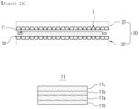
- FIG. 1 shows a schematic diagram of a longitudinal cross-section of the secondary battery lamination device according to an embodiment of the present invention.
- the secondary battery lamination device 1 comprises the laminate moving portion 10 for moving the laminate 11 formed by sequentially stacking the positive electrode 11c, the separator 11b and the negative electrode 11a in one direction; the infrared LED (Light-Emitting Diode) heat source portion 20 which is positioned on one side and/or the other side of the laminate moving portion 10 and supplies infrared light to the laminate 11 to bond the positive electrode 11c, the separator 11b and the negative electrode 11a; and the pressurizing portion 30 for pressurizing the laminate 11 that has passed through the laminate moving portion 10.
- the one direction may mean a horizontal direction parallel to the laminate moving portion, and the one side and the other side may mean the upper portion and the lower portion.
- the laminate moving portion 10 can move the laminate 11 in one direction, and can supply infrared light to the laminate 11 to bond the positive electrode 11c, the separator 11b, and the negative electrode 11a.
- the laminate 11 may be a mono cell-type structure in which the separator 11b, the negative electrode 11a, the separator 11b, and a positive electrode 11c are sequentially stacked. In addition, it can be transformed into various forms such as the laminate mono cell as well as the bi-cell.
- the laminate moving portion 10 may be in the form of a conveyor belt formed on a second infrared LED heat source portion 22.
- the conveyor belt generally refers to a belt-shaped device that continuously moves and/or transports objects, and is not particularly limited as long as it is a conveyor belt commonly used in the art.
- the conveyor belt that can be applied to the laminate moving portion 10 may include a belt portion that is wound around a first roller and a second roller that are respectively disposed at both ends in the longitudinal direction to rotate.
- the longitudinal direction may mean one direction in which the laminate moves.
- the length of the laminate moving portion 10 is shortened compared to when using a conventional heater, thereby increasing the process efficiency and reducing the equipment cost.
- the infrared LED heat source portion 20 directly applies heat to the laminate using a plurality of infrared LED lamps, it can apply heat to the laminate uniformly even if the length is shorter than that of the laminate moving portion 10 using a heater, and it is easy to control the output of individual infrared LED lamps, thereby facilitating the control of the quality.
- the infrared LED heat source portion 20 as a heat source in the secondary battery lamination device 1, it is possible to shorten the length of the laminate moving portion 10 to about 50% to 60% or about 58.7% compared to when using a general heater.
- the infrared LED (Light-Emitting Diode) heat source portion 20 may supply infrared light to the laminate 11, which is moved in one direction through the laminate moving portion 10, to bond the positive electrode 11c, the separator 11b, and the negative electrode 11a comprised in the laminate 11.
- FIGS. 2A to 2C are schematic diagrams showing the structure of the infrared LED heat source portion according to one embodiment of the present invention and the arrangement form of the infrared LED lamps contained in the inside thereof.
- the infrared LED heat source portion 20 may comprise a first infrared LED heat source portion 21 that supplies infrared light from one side of the laminate 11 and the second infrared LED heat source portion 22 that supplies infrared light from the other side of the laminate 11.
- the first infrared LED heat source portion 21 may be located above the laminate moving portion 10, and the second infrared LED heat source portion 22 may be located below the laminate moving portion 10.
- the number and arrangement form of the plurality of infrared LED lamps included in the first infrared LED heat source portion 21 and the second infrared LED heat source portion 22 may be the same, and in this case, the laminate 11 can be bonded more uniformly, thereby improving the quality of the manufactured secondary battery.
- the laminate moving portion 10 may be adjacently formed on the second infrared LED heat source portion 22.
- the infrared LED heat source portion 20 may comprise a plurality of infrared LED lamps (L), and the plurality of infrared LED lamps (L) included in the first infrared LED heat source portion 21 and the second infrared LED heat source portion 22 may be arranged symmetrically with respect to the laminate moving portion 10.
- the plurality of infrared LED lamps (L) may be individually operated.
- the individual operating may mean that lamps are individually turned on/off or that their output is individually regulated. Therefore, when the laminate 11 is moved by the laminate moving portion 10, the output of the infrared LED lamp (L) may be individually controlled so that the laminate 11 is uniformly adhered and the uniformity of air permeability is improved, thereby improving the reliability of the quality of the manufactured electrode.
- the maintenance time of the secondary battery lamination device can also be shortened.
- FIG. 2B shows an example of an arrangement form of the infrared LED lamps (L) arranged in the second infrared LED heat source portion 22.
- the first infrared LED heat source portion 21 may also have the same shape.
- the infrared LED lamps(L) may be arranged adjacent to each other in a line in the laminate moving portion 10 in a direction perpendicular to the laminate moving direction ( ⁇ ).
- the infrared LED lamps (L) arranged in a line like this are called a LED line (LL), and a plurality of LED lines (LL) may be arranged in a direction parallel to the laminate moving direction ( ⁇ ), and a plurality of LED lines (LL) may be arranged adjacent or spaced apart from each other at regular intervals.
- the longitudinal length of the array comprising the n LED lamps (L) is called an overall length (OL) and the lateral length is called an overall width (OW).
- the first infrared LED heat source portion 21 may comprise an arrangement of 1 set or more or 1 to 5 sets of infrared LED lamps.
- Figure 2C shows a shape in which a plurality of laminates 10 are transferred in one direction ( ⁇ ) on the second infrared LED heat source portion 22 comprising three sets (#1, #2, #3) of arrangements comprising the n infrared LED lamps (L).
- the pressurizing portion 30 may include a lamination roller 31.
- the lamination roller 31 may pressurize the laminate 11 that has passed through the laminate moving portion 10 to obtain a battery.
- the lamination roller 31 includes a pair of rollers and means rollers capable of laminating laminates passing between the pair of rollers.
- the lamination roller 31 may be used without limitation as long as it is commonly used rollers in the art.
- the pressure applied to the laminate 11 that has passed through the laminate moving portion 10 is not particularly limited as long as the pressure is sufficient to manufacture a secondary battery by bonding the laminate 11.
- the pressure of about 900 to 1000 kg may be applied by appropriately adjusting the pressurization pressure in consideration of the adhesive strength, the air permeability, and the process efficiency of the secondary battery.
- FIG. 3 is a schematic diagram of a longitudinal cross-section of the secondary battery lamination device according to another embodiment of the present invention.
- the secondary battery lamination device 1 comprises the laminate moving portion 10 for moving the laminate 11 formed by sequentially stacking the positive electrode 11c, the separator 11b and the negative electrode 11a in one direction; the infrared LED heat source portion 20 which is positioned on one side or the other side of the laminate moving portion 10 and supplies infrared light to the laminate 11 to bond the positive electrode 11c, the separator 11b and the negative electrode 11a; and the pressurizing portion (not shown) for pressurizing the laminate 11 that has passed through the laminate moving portion 10.
- the secondary battery lamination device 1 comprises fan sheets 40 comprising the upper fan sheet 41 and the lower fan sheet 42 formed adjacent to the first infrared LED heat source portion 21 and the second infrared LED heat source portion 22.
- the upper fan sheet 41 and the lower fan sheet 42 comprises a plurality of fans 41a, 41b, 41c, 42a, 42b, and 42c, respectively.
- the plurality of fans 41a, 41b, 41c, 42a, 42b, and 42c may cool the infrared LED heat source portion 20 to prevent overheating.
- the fan sheet 40 is for cooling the infrared LED heat source portion 20
- the fan sheet 40 may be coupled to the infrared LED heat source portion 20 without being spaced apart or may be spaced apart from the infrared LED heat source portion 20 by a predetermined interval or less to exhibit a cooling effect.
- the secondary battery lamination device 1 comprises an electronic box 50 which comprises a control portion for controlling the operation of each component comprising the laminate moving portion 10, the infrared LED heat source portion 20, the pressurizing portion (not shown) and the fan sheet 40 as described above.
- the electronic box 50 comprises the upper electronic box 51 and the lower electronic box 52, and the upper electronic box 51 may be formed adjacent to the first infrared LED heat source portion 21 and the upper fan sheet 41, and the lower electronic box 52 may be formed to be spaced apart from or coupled to the second infrared LED heat source portion 22 and the lower fan sheet 42.
- a secondary battery in the form of a semi-finished product may be manufactured using the secondary battery lamination device according to the present invention.
- the battery in the form of the semi-finished product may include a positive electrode, a separator and a negative electrode.
- the secondary battery lamination device can control the operation of individual infrared LED lamps by using the infrared LED heat source portion, the maintenance of the infrared LED heat source portion is easy, and the adhesive strength and the air permeability between the positive electrode, the separator and the positive electrode included in the battery can be improved.
- the infrared LED heat source portion may improve the lamination efficiency of the electrode laminate by the heat source portion having a relatively short length, as compared to the heat source portion where a general heater is installed, thereby reducing the equipment cost.
- the infrared LED lamp comprised in the infrared LED heat source portion can be easily replaced and used for a long period of time, thereby improving the process efficiency and reducing the equipment cost.
- the output of the corresponding individual infrared LED lamp can be controlled to raise the temperature of the first temperature detection sensor connection portion 60a.
- the secondary battery lamination device has the advantage of being able to independently control the output of individual infrared LED lamps by sensing the temperature of the laminate in real time.
Landscapes
- Engineering & Computer Science (AREA)
- Manufacturing & Machinery (AREA)
- Chemical & Material Sciences (AREA)
- Chemical Kinetics & Catalysis (AREA)
- Electrochemistry (AREA)
- General Chemical & Material Sciences (AREA)
- Secondary Cells (AREA)
Abstract
Description
- This application claims the benefits of priorities based on
Korean Patent Application No. 2021-0085047 filed on June 29, 2021 Korean Patent Application No. 2022-0077548 filed on June 24, 2022 - One aspect of the present disclosure relates to a secondary battery lamination device using infrared lamps.
- The secondary battery can be classified in various ways according to the structure of the electrode assembly. As an example, the secondary battery may be classified into a stack type structure, a winding type (jelly roll type) structure, or a stack/folding type structure. However, in the stack type structure, since the electrode units (positive electrode, separator and negative electrode) constituting the electrode assembly are stacked separately from each other, not only it is very difficult to precisely align the electrode assembly, but also there is a disadvantage that a very large number of processes are required to produce the electrode assembly.
-
Japanese Publication Patent Application No. 2012-146850 - Therefore, it is required to develop a technology that can improve the quality of the product as well as process efficiency by performing lamination more efficiently during the electrode manufacturing process.
- (Patent Document 1)
Japanese Publication Patent Application No. 2012-146850 - The inventors of one aspect of the present disclosure have conducted various studies to solve the above problems, and as a result, have confirmed that when heat is applied using an infrared LED heat source portion that includes a plurality of infrared LED lamps with individually controllable output during the lamination process of the electrode laminate using heat and pressure, the adhesive strength and air permeability of the electrode can be made more uniformly, which can improve the reliability of the quality of the electrode.
- Accordingly, it is an object of the present invention to provide a secondary battery lamination device using infrared lamps.
- In order to achieve the above purpose, one aspect of the present disclosure provides a secondary battery lamination device using infrared lamps, comprising: a laminate moving portion configured to move a laminate in a first direction, the laminate formed by sequentially stacking a positive electrode, a separator, and a negative electrode;
- an infrared LED (Light-Emitting Diode) heat source portion positioned on a first side or the first side and a second side of the laminate moving portion, the infrared LED heat source portion configured to supply infrared light to the laminate to bond the positive electrode, the separator, and the negative electrode to one another; and
- a pressurizing portion configured to apply a pressure to the laminate, the pressurizing portion being disposed downstream of the infrared LED heat source portion in the first direction.
- Since the secondary battery lamination device using the infrared lamp according to the present invention can individually control the output of a plurality of infrared LED lamps comprised in the infrared LED heat source portion, it can improve the quality of the electrode and the process efficiency, by making uniform the adhesive strength and air permeability between each layer comprised in the secondary battery manufactured by the lamination process.
- In addition, the infrared LED heat source portion can improve the lamination efficiency of the electrode laminate by a relatively short heat source portion compared to a heat source portion in which a general heater is installed, thereby reducing the equipment cost.
- In addition, the infrared LED lamp comprised in the infrared LED heat source portion is easy to replace and has a long usage period, thereby improving the process efficiency and reducing the equipment cost.
-
-
FIG. 1 shows a schematic diagram of a longitudinal cross-section of the secondary battery lamination device according to an embodiment of the present invention. -
FIGS. 2A to 2C are schematic diagrams showing the structure of the infrared LED heat source portion according to an embodiment of the present invention and the arrangement form of the LED lamps contained in the inside thereof. -
FIG. 3 is a schematic diagram of a longitudinal cross-section of the secondary battery lamination device according to another embodiment of the present invention. -
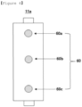
FIG. 4 is a schematic diagram in which a temperature sensor is connected to the positive electrode comprised in the laminate manufactured by the secondary battery lamination device according to another embodiment of the present invention. - Hereinafter, the present invention will be described in more detail to help the understanding of the present invention.
- The terms and words used in the present specification and claims should not be construed as limited to ordinary or dictionary terms, and should be construed in a sense and concept consistent with the technical idea of the present invention, based on the principle that the inventor can properly define the concept of a term to describe his/her invention in the best way possible.
- As used herein, the term "secondary battery lamination device" refers to a device for a lamination process that bonds laminates, which are formed by sequentially stacking a positive electrode, a separator, and a negative electrode, to each other, when manufacturing a secondary battery comprising the positive electrode, the separator and the negative electrode.
- As used herein, the term "laminate" refers to a structure in which a positive electrode, a separator, and a negative electrode are simply stacked.
- As used herein, the term "lamination" means that a positive electrode, a separator, and a negative electrode comprised in the laminate are bonded by heat and pressure.
- As used herein, the term "infrared LED heat source portion" refers to a member comprising a plurality of infrared LED lamps emitting infrared.
- One aspect of the present disclosure relates to a secondary battery lamination device using infrared LED lamps, comprising a laminate moving portion for moving a laminate formed by sequentially stacking a positive electrode, a separator and a negative electrode in one direction; an infrared LED (Light-Emitting Diode) heat source portion which is positioned on one side and/or the other side of the laminate moving portion and supplies infrared light to the laminate to bond the positive electrode, the separator and the negative electrode; and a pressurizing portion for pressurizing the laminate bonded by the infrared LED heat source portion while passing through the laminate moving portion.
- If infrared light is supplied from the infrared LED heat source portion, the interfaces of the positive electrode, the separator, and the negative electrode included in the laminate are partially melted and changed to a state where adhesion is easy, and then if pressurization is performed from the pressurizing portion, a laminate laminated with high adhesive strength can be obtained. The laminated laminate may comprise a semi-finished battery, that is, the laminated positive electrode, separator, and negative electrode.
- Hereinafter, with reference to
FIGS. 1 to 4 , the secondary battery lamination device according to the present invention will be described in more detail.FIGS. 1 to 4 correspond to an embodiment of the secondary battery lamination device, and the secondary battery lamination device according to the present invention is not limited by the drawings. -
FIG. 1 shows a schematic diagram of a longitudinal cross-section of the secondary battery lamination device according to an embodiment of the present invention. - Referring to
FIG. 1 , the secondary battery lamination device 1 comprises thelaminate moving portion 10 for moving thelaminate 11 formed by sequentially stacking thepositive electrode 11c, theseparator 11b and thenegative electrode 11a in one direction; the infrared LED (Light-Emitting Diode)heat source portion 20 which is positioned on one side and/or the other side of thelaminate moving portion 10 and supplies infrared light to thelaminate 11 to bond thepositive electrode 11c, theseparator 11b and thenegative electrode 11a; and the pressurizingportion 30 for pressurizing thelaminate 11 that has passed through thelaminate moving portion 10. In this case, the one direction may mean a horizontal direction parallel to the laminate moving portion, and the one side and the other side may mean the upper portion and the lower portion. - In one aspect of the present disclosure, the
laminate moving portion 10 can move thelaminate 11 in one direction, and can supply infrared light to thelaminate 11 to bond thepositive electrode 11c, theseparator 11b, and thenegative electrode 11a. - According to one embodiment, the
laminate 11 may be a mono cell-type structure in which theseparator 11b, thenegative electrode 11a, theseparator 11b, and apositive electrode 11c are sequentially stacked. In addition, it can be transformed into various forms such as the laminate mono cell as well as the bi-cell. - The
laminate moving portion 10 may be in the form of a conveyor belt formed on a second infrared LEDheat source portion 22. In this case, the conveyor belt generally refers to a belt-shaped device that continuously moves and/or transports objects, and is not particularly limited as long as it is a conveyor belt commonly used in the art. For example, the conveyor belt that can be applied to thelaminate moving portion 10 may include a belt portion that is wound around a first roller and a second roller that are respectively disposed at both ends in the longitudinal direction to rotate. In this case, the longitudinal direction may mean one direction in which the laminate moves. - As the infrared LED
heat source portion 20 to be described later is used, the length of thelaminate moving portion 10 is shortened compared to when using a conventional heater, thereby increasing the process efficiency and reducing the equipment cost. - Since conventional general heaters apply heat to the laminate by convection, the temperature applied to the laminate may be non-uniform, and thus there was a problem that the quality of the lamination secondary battery had to be adjusted by increasing the surface temperature of the pressurizing portion roller. Since the size of the heater using convection is large, there is a problem that the length of the
laminate moving portion 10 itself becomes long. - However, since the infrared LED
heat source portion 20 directly applies heat to the laminate using a plurality of infrared LED lamps, it can apply heat to the laminate uniformly even if the length is shorter than that of thelaminate moving portion 10 using a heater, and it is easy to control the output of individual infrared LED lamps, thereby facilitating the control of the quality. - For example, in the case of using the infrared LED
heat source portion 20 as a heat source in the secondary battery lamination device 1, it is possible to shorten the length of thelaminate moving portion 10 to about 50% to 60% or about 58.7% compared to when using a general heater. - In one aspect of the present disclosure, the infrared LED (Light-Emitting Diode)
heat source portion 20 may supply infrared light to thelaminate 11, which is moved in one direction through thelaminate moving portion 10, to bond thepositive electrode 11c, theseparator 11b, and thenegative electrode 11a comprised in thelaminate 11. -
FIGS. 2A to 2C are schematic diagrams showing the structure of the infrared LED heat source portion according to one embodiment of the present invention and the arrangement form of the infrared LED lamps contained in the inside thereof. - Referring to
FIG. 2A , the infrared LEDheat source portion 20 may comprise a first infrared LEDheat source portion 21 that supplies infrared light from one side of thelaminate 11 and the second infrared LEDheat source portion 22 that supplies infrared light from the other side of thelaminate 11. The first infrared LEDheat source portion 21 may be located above thelaminate moving portion 10, and the second infrared LEDheat source portion 22 may be located below thelaminate moving portion 10. The number and arrangement form of the plurality of infrared LED lamps included in the first infrared LEDheat source portion 21 and the second infrared LEDheat source portion 22 may be the same, and in this case, thelaminate 11 can be bonded more uniformly, thereby improving the quality of the manufactured secondary battery. Thelaminate moving portion 10 may be adjacently formed on the second infrared LEDheat source portion 22. - The infrared LED
heat source portion 20 may comprise a plurality of infrared LED lamps (L), and the plurality of infrared LED lamps (L) included in the first infrared LEDheat source portion 21 and the second infrared LEDheat source portion 22 may be arranged symmetrically with respect to thelaminate moving portion 10. - The plurality of infrared LED lamps (L) may be individually operated. In this case, the individual operating may mean that lamps are individually turned on/off or that their output is individually regulated. Therefore, when the laminate 11 is moved by the
laminate moving portion 10, the output of the infrared LED lamp (L) may be individually controlled so that the laminate 11 is uniformly adhered and the uniformity of air permeability is improved, thereby improving the reliability of the quality of the manufactured electrode. In addition, due to the individual operating of the plurality of infrared LED lamps (L), the maintenance time of the secondary battery lamination device can also be shortened. -
FIG. 2B shows an example of an arrangement form of the infrared LED lamps (L) arranged in the second infrared LEDheat source portion 22. The first infrared LEDheat source portion 21 may also have the same shape. - The infrared LED lamps(L) may be arranged adjacent to each other in a line in the
laminate moving portion 10 in a direction perpendicular to the laminate moving direction (→). The infrared LED lamps (L) arranged in a line like this are called a LED line (LL), and a plurality of LED lines (LL) may be arranged in a direction parallel to the laminate moving direction (→), and a plurality of LED lines (LL) may be arranged adjacent or spaced apart from each other at regular intervals. - For example, the total number of LED lamps (L) comprised in the array in which the number of infrared LED lamps (L) arranged adjacently in one LED line (LL) is a (wherein, a is an integer greater than or equal to 1) and the number of the arranged LED lines (LL) is b (wherein, b is an integer greater than or equal to 1) may be n (wherein, n = a x b). At this time, the longitudinal length of the array comprising the n LED lamps (L) is called an overall length (OL) and the lateral length is called an overall width (OW).
- When such an arrangement of the LED lamps (L) is referred to as one set, the first infrared LED
heat source portion 21 may comprise an arrangement of 1 set or more or 1 to 5 sets of infrared LED lamps. -
Figure 2C shows a shape in which a plurality oflaminates 10 are transferred in one direction (→) on the second infrared LEDheat source portion 22 comprising three sets (#1, #2, #3) of arrangements comprising the n infrared LED lamps (L). - In one aspect of the present disclosure, the pressurizing
portion 30 may include a lamination roller 31. The lamination roller 31 may pressurize the laminate 11 that has passed through thelaminate moving portion 10 to obtain a battery. The lamination roller 31 includes a pair of rollers and means rollers capable of laminating laminates passing between the pair of rollers. The lamination roller 31 may be used without limitation as long as it is commonly used rollers in the art. - At this time, the pressure applied to the laminate 11 that has passed through the
laminate moving portion 10 is not particularly limited as long as the pressure is sufficient to manufacture a secondary battery by bonding thelaminate 11. For example, the pressure of about 900 to 1000 kg may be applied by appropriately adjusting the pressurization pressure in consideration of the adhesive strength, the air permeability, and the process efficiency of the secondary battery. -
FIG. 3 is a schematic diagram of a longitudinal cross-section of the secondary battery lamination device according to another embodiment of the present invention. - Referring to
FIG. 3 , the secondary battery lamination device 1 comprises thelaminate moving portion 10 for moving the laminate 11 formed by sequentially stacking thepositive electrode 11c, theseparator 11b and thenegative electrode 11a in one direction; the infrared LEDheat source portion 20 which is positioned on one side or the other side of thelaminate moving portion 10 and supplies infrared light to the laminate 11 to bond thepositive electrode 11c, theseparator 11b and thenegative electrode 11a; and the pressurizing portion (not shown) for pressurizing the laminate 11 that has passed through thelaminate moving portion 10. - In addition, the secondary battery lamination device 1 comprises
fan sheets 40 comprising theupper fan sheet 41 and thelower fan sheet 42 formed adjacent to the first infrared LEDheat source portion 21 and the second infrared LEDheat source portion 22. Theupper fan sheet 41 and thelower fan sheet 42 comprises a plurality offans fans heat source portion 20 to prevent overheating. Since thefan sheet 40 is for cooling the infrared LEDheat source portion 20, thefan sheet 40 may be coupled to the infrared LEDheat source portion 20 without being spaced apart or may be spaced apart from the infrared LEDheat source portion 20 by a predetermined interval or less to exhibit a cooling effect. - In addition, the secondary battery lamination device 1 comprises an
electronic box 50 which comprises a control portion for controlling the operation of each component comprising thelaminate moving portion 10, the infrared LEDheat source portion 20, the pressurizing portion (not shown) and thefan sheet 40 as described above. Theelectronic box 50 comprises the upperelectronic box 51 and the lowerelectronic box 52, and the upperelectronic box 51 may be formed adjacent to the first infrared LEDheat source portion 21 and theupper fan sheet 41, and the lowerelectronic box 52 may be formed to be spaced apart from or coupled to the second infrared LEDheat source portion 22 and thelower fan sheet 42. - A secondary battery in the form of a semi-finished product may be manufactured using the secondary battery lamination device according to the present invention. The battery in the form of the semi-finished product may include a positive electrode, a separator and a negative electrode.
- Since the secondary battery lamination device can control the operation of individual infrared LED lamps by using the infrared LED heat source portion, the maintenance of the infrared LED heat source portion is easy, and the adhesive strength and the air permeability between the positive electrode, the separator and the positive electrode included in the battery can be improved.
- In addition, the infrared LED heat source portion may improve the lamination efficiency of the electrode laminate by the heat source portion having a relatively short length, as compared to the heat source portion where a general heater is installed, thereby reducing the equipment cost.
- In addition, the infrared LED lamp comprised in the infrared LED heat source portion can be easily replaced and used for a long period of time, thereby improving the process efficiency and reducing the equipment cost.
- For example, if the temperature sensed through the first temperature detection
sensor connection portion 60a of thepositive electrode 11a is low, the output of the corresponding individual infrared LED lamp can be controlled to raise the temperature of the first temperature detectionsensor connection portion 60a. - As described above, the secondary battery lamination device according to the present invention has the advantage of being able to independently control the output of individual infrared LED lamps by sensing the temperature of the laminate in real time.
- In the above, although the present invention has been described by way of limited embodiments and drawings, the present invention is not limited thereto, and it is apparent to those skilled in the art that various modifications and variations can be made within the equivalent scope of the technical spirit of the present invention and the claims to be described below.
[Description of Symbol] 1: Secondary battery lamination device 10: Laminate moving portion 11: Laminate 11a: Negative electrode 11b: Separator 11c: Positive electrode 20: Infrared LED heat source portion 21: First infrared LED heat source portion 22: Second infrared LED heat source portion L: infrared LED lamp LL: LED line 30: Pressurizing portion 31: Lamination roller 40: Fan sheet 41: Upper fan sheet 42: Lower fan sheet 41a, 41b, 41c: Upper fan 42a, 42b, 42c: Lower fan 50: Electronic box 51: Upper electronic box 52: Lower electronic box 60: Temperature sensor connection portion 60a: First temperature sensor connection portion 60b: Second temperature sensor connection portion 60c: Third temperature sensor connection portion
Claims (11)
- A secondary battery lamination device using infrared lamps comprising:a laminate moving portion configured to move a laminate in a first direction, the laminate formed by sequentially stacking a positive electrode, a separator, and a negative electrode;an infrared LED (Light-Emitting Diode) heat source portion positioned on a first side or the first side and a second side of the laminate moving portion, the infrared LED heat source portion configured to supply infrared light to the laminate to bond the positive electrode, the separator, and the negative electrode to one another; anda pressurizing portion configured to apply a pressure to the laminate, the pressurizing portion being disposed downstream of the infrared LED heat source portion in the first direction.
- The secondary battery lamination device according to claim 1, wherein the infrared LED heat source portion comprises a first infrared LED heat source portion positioned on the first side of the laminate moving portion and a second infrared LED heat source portion positioned on the second side of the laminate moving portion.
- The secondary battery lamination device according to claim 1, wherein the laminate moving portion is in the form of a conveyor belt.
- The secondary battery lamination device according to claim 2, wherein the first infrared LED heat source portion and the second infrared LED heat source portion each comprise a respective plurality of infrared LED lamps arranged symmetrically based on a centerline of the laminate moving portion.
- The secondary battery lamination device according to claim 4, wherein with respect to the plurality of infrared LED lamps of each of the first and second infrared LED heat source portions, when an array of matrix form (a * b) having a vertically and b horizontally is defined as one set, 1 to 5 sets of the LED lamps are disposed in each of the first and second infrared LED heat source portions.
- The secondary battery lamination device according to claim 4, wherein the infrared LED lamps of each of the first and second LED heat source portions are operated individually.
- The secondary battery lamination device according to claim 1, wherein the pressurizing portion comprises a roller.
- The secondary battery lamination device according to claim 1, wherein the pressurizing portion is configured to apply the pressure to the laminate of 900 to 1000 kg.
- The secondary battery lamination device according to claim 1, further comprising a fan sheet disposed adjacent to the infrared LED heat source portion, the fan sheet comprising a plurality of fans.
- The secondary battery lamination device according to claim 1, further comprising an electronic box having a control portion configured to control operation of the laminate moving portion, the infrared LED heat source portion, and the pressurizing portion.
- The secondary battery lamination device according to claim 1, further comprising a temperature sensor configured to be connected to the positive electrode and/or the negative electrode.
Applications Claiming Priority (3)
| Application Number | Priority Date | Filing Date | Title |
|---|---|---|---|
| KR20210085047 | 2021-06-29 | ||
| KR1020220077548A KR20230002079A (en) | 2021-06-29 | 2022-06-24 | Lamination apparatus for secondary battery using infrared lamp |
| PCT/KR2022/009092 WO2023277471A1 (en) | 2021-06-29 | 2022-06-27 | Secondary battery lamination device using infrared lamps |
Publications (3)
| Publication Number | Publication Date |
|---|---|
| EP4199164A1 true EP4199164A1 (en) | 2023-06-21 |
| EP4199164A4 EP4199164A4 (en) | 2024-08-14 |
| EP4199164B1 EP4199164B1 (en) | 2025-05-21 |
Family
ID=84691935
Family Applications (1)
| Application Number | Title | Priority Date | Filing Date |
|---|---|---|---|
| EP22833527.9A Active EP4199164B1 (en) | 2021-06-29 | 2022-06-27 | Secondary battery lamination device using infrared lamps |
Country Status (6)
| Country | Link |
|---|---|
| US (1) | US20230371131A1 (en) |
| EP (1) | EP4199164B1 (en) |
| CN (1) | CN116250374A (en) |
| ES (1) | ES3037996T3 (en) |
| HU (1) | HUE072200T2 (en) |
| WO (1) | WO2023277471A1 (en) |
Family Cites Families (12)
| Publication number | Priority date | Publication date | Assignee | Title |
|---|---|---|---|---|
| JPH11339783A (en) * | 1998-04-22 | 1999-12-10 | Mitsubishi Chemical Corp | Manufacturing method of battery electrode using infrared irradiation |
| KR101286003B1 (en) * | 2006-03-09 | 2013-07-15 | 삼성에스디아이 주식회사 | Method of drying slurry for electrode of rechargeable battery and Apparatus for the same |
| JP5271366B2 (en) | 2011-01-13 | 2013-08-21 | 東京エレクトロン株式会社 | Electrode manufacturing apparatus, electrode manufacturing method, program, and computer storage medium |
| KR101666371B1 (en) * | 2013-09-30 | 2016-10-14 | 주식회사 엘지화학 | Electrode Rolling Device Having Heater |
| KR20150037227A (en) * | 2013-09-30 | 2015-04-08 | 주식회사 엘지화학 | Electrode Drying Device Having N-IR Heater |
| KR102516223B1 (en) * | 2017-08-17 | 2023-03-30 | 주식회사 엘지에너지솔루션 | Heating device for electrode and manufacturing system for secondary battery comprising the same |
| KR102504756B1 (en) * | 2018-05-17 | 2023-03-02 | 주식회사 엘지에너지솔루션 | Lamination apparatus and Lamination method for electrode |
| WO2020106033A1 (en) * | 2018-11-19 | 2020-05-28 | 주식회사 엘지화학 | Method for manufacturing cylindrical battery and drying apparatus for performing same |
| KR101988597B1 (en) * | 2018-11-28 | 2019-06-13 | 한국건설기술연구원 | Laminating Apparatus for Manufacturing Incombustible Composite Panel And Method for Manufacturing Incombustible Composite Panel Using the Same |
| KR102580441B1 (en) * | 2019-03-06 | 2023-09-20 | 주식회사 엘지에너지솔루션 | The Apparatus And The Method For Manufacturing Cell |
| KR102348488B1 (en) | 2019-12-30 | 2022-01-07 | 재단법인 베리앤바이오식품연구소 | stick type jelly using composition of antibiotic activity and antioxidants for diseases related respiratory |
| KR102448279B1 (en) | 2020-12-02 | 2022-09-27 | 박전진 | Hexa driver for implant surgery with safety wire |
-
2022
- 2022-06-27 US US18/030,016 patent/US20230371131A1/en active Pending
- 2022-06-27 CN CN202280006617.7A patent/CN116250374A/en active Pending
- 2022-06-27 HU HUE22833527A patent/HUE072200T2/en unknown
- 2022-06-27 ES ES22833527T patent/ES3037996T3/en active Active
- 2022-06-27 WO PCT/KR2022/009092 patent/WO2023277471A1/en not_active Ceased
- 2022-06-27 EP EP22833527.9A patent/EP4199164B1/en active Active
Also Published As
| Publication number | Publication date |
|---|---|
| CN116250374A (en) | 2023-06-09 |
| WO2023277471A1 (en) | 2023-01-05 |
| EP4199164A4 (en) | 2024-08-14 |
| ES3037996T3 (en) | 2025-10-08 |
| EP4199164B1 (en) | 2025-05-21 |
| HUE072200T2 (en) | 2025-10-28 |
| US20230371131A1 (en) | 2023-11-16 |
Similar Documents
| Publication | Publication Date | Title |
|---|---|---|
| US8052036B2 (en) | Tab lead soldering apparatus and tab lead soldering method | |
| CN101740792B (en) | Manufacturing of fuel cells | |
| KR102025664B1 (en) | Tabbing apparatus and controling method thereof | |
| KR102362627B1 (en) | Method For Applying Optical Film To Optical Display Cell | |
| US20170069926A1 (en) | Heat treatment device of membrane-electrode assembly (mea) for fuel cell | |
| JP5225164B2 (en) | Solar cell laminating apparatus and laminating method | |
| TWI273627B (en) | Photosensitive resin transfer printing equipment and methods | |
| KR101702419B1 (en) | Apparatus for Fabricating the Laminated Body of Fuel Cell | |
| EP4199164A1 (en) | Secondary battery lamination device using infrared lamps | |
| KR102176213B1 (en) | Tabbing apparatus | |
| JP6598521B2 (en) | Vacuum lamination method | |
| KR20230002079A (en) | Lamination apparatus for secondary battery using infrared lamp | |
| JP6225020B2 (en) | Laminator | |
| CN108207077B (en) | Combination system and manufacturing method thereof | |
| CN108140599B (en) | Manufacture and use method of pressure heating rolling machine | |
| JP2010171048A (en) | Method and device for manufacturing ceramic laminated body | |
| JP2007036198A (en) | Printed wiring board and manufacturing method thereof | |
| JP4562047B1 (en) | Solar cell module manufacturing method and apparatus | |
| JP4519732B2 (en) | Metal foil resin film laminate production equipment | |
| KR20170034764A (en) | Double structure type heat roller equipped in FFC, laminating method using the same | |
| CN116278329A (en) | Lamination device and lamination method | |
| JP6335677B2 (en) | Solar cell module manufacturing equipment | |
| CN115416278B (en) | PVC floor manufacturing equipment and method | |
| CN223545947U (en) | Device for hot-pressing and laminating materials | |
| CN223927576U (en) | Diaphragm composite device |
Legal Events
| Date | Code | Title | Description |
|---|---|---|---|
| STAA | Information on the status of an ep patent application or granted ep patent |
Free format text: STATUS: THE INTERNATIONAL PUBLICATION HAS BEEN MADE |
|
| PUAI | Public reference made under article 153(3) epc to a published international application that has entered the european phase |
Free format text: ORIGINAL CODE: 0009012 |
|
| STAA | Information on the status of an ep patent application or granted ep patent |
Free format text: STATUS: REQUEST FOR EXAMINATION WAS MADE |
|
| 17P | Request for examination filed |
Effective date: 20230317 |
|
| AK | Designated contracting states |
Kind code of ref document: A1 Designated state(s): AL AT BE BG CH CY CZ DE DK EE ES FI FR GB GR HR HU IE IS IT LI LT LU LV MC MK MT NL NO PL PT RO RS SE SI SK SM TR |
|
| A4 | Supplementary search report drawn up and despatched |
Effective date: 20240716 |
|
| RIC1 | Information provided on ipc code assigned before grant |
Ipc: H05B 1/02 20060101ALI20240710BHEP Ipc: H01M 10/0585 20100101ALI20240710BHEP Ipc: H05B 3/00 20060101ALI20240710BHEP Ipc: H01M 10/04 20060101AFI20240710BHEP |
|
| DAV | Request for validation of the european patent (deleted) | ||
| DAX | Request for extension of the european patent (deleted) | ||
| GRAP | Despatch of communication of intention to grant a patent |
Free format text: ORIGINAL CODE: EPIDOSNIGR1 |
|
| STAA | Information on the status of an ep patent application or granted ep patent |
Free format text: STATUS: GRANT OF PATENT IS INTENDED |
|
| INTG | Intention to grant announced |
Effective date: 20250213 |
|
| GRAS | Grant fee paid |
Free format text: ORIGINAL CODE: EPIDOSNIGR3 |
|
| GRAA | (expected) grant |
Free format text: ORIGINAL CODE: 0009210 |
|
| STAA | Information on the status of an ep patent application or granted ep patent |
Free format text: STATUS: THE PATENT HAS BEEN GRANTED |
|
| P01 | Opt-out of the competence of the unified patent court (upc) registered |
Free format text: CASE NUMBER: APP_14046/2025 Effective date: 20250321 |
|
| AK | Designated contracting states |
Kind code of ref document: B1 Designated state(s): AL AT BE BG CH CY CZ DE DK EE ES FI FR GB GR HR HU IE IS IT LI LT LU LV MC MK MT NL NO PL PT RO RS SE SI SK SM TR |
|
| REG | Reference to a national code |
Ref country code: GB Ref legal event code: FG4D |
|
| REG | Reference to a national code |
Ref country code: CH Ref legal event code: EP |
|
| REG | Reference to a national code |
Ref country code: DE Ref legal event code: R096 Ref document number: 602022015056 Country of ref document: DE |
|
| REG | Reference to a national code |
Ref country code: IE Ref legal event code: FG4D |
|
| PGFP | Annual fee paid to national office [announced via postgrant information from national office to epo] |
Ref country code: DE Payment date: 20250609 Year of fee payment: 4 |
|
| PGFP | Annual fee paid to national office [announced via postgrant information from national office to epo] |
Ref country code: BE Payment date: 20250609 Year of fee payment: 4 |
|
| PGFP | Annual fee paid to national office [announced via postgrant information from national office to epo] |
Ref country code: FR Payment date: 20250611 Year of fee payment: 4 |
|
| PGFP | Annual fee paid to national office [announced via postgrant information from national office to epo] |
Ref country code: AT Payment date: 20250721 Year of fee payment: 4 |
|
| PGFP | Annual fee paid to national office [announced via postgrant information from national office to epo] |
Ref country code: HU Payment date: 20250827 Year of fee payment: 4 |
|
| REG | Reference to a national code |
Ref country code: NL Ref legal event code: MP Effective date: 20250521 |
|
| REG | Reference to a national code |
Ref country code: ES Ref legal event code: FG2A Ref document number: 3037996 Country of ref document: ES Kind code of ref document: T3 Effective date: 20251008 |
|
| PG25 | Lapsed in a contracting state [announced via postgrant information from national office to epo] |
Ref country code: FI Free format text: LAPSE BECAUSE OF FAILURE TO SUBMIT A TRANSLATION OF THE DESCRIPTION OR TO PAY THE FEE WITHIN THE PRESCRIBED TIME-LIMIT Effective date: 20250521 Ref country code: PT Free format text: LAPSE BECAUSE OF FAILURE TO SUBMIT A TRANSLATION OF THE DESCRIPTION OR TO PAY THE FEE WITHIN THE PRESCRIBED TIME-LIMIT Effective date: 20250922 |
|
| PGFP | Annual fee paid to national office [announced via postgrant information from national office to epo] |
Ref country code: ES Payment date: 20250714 Year of fee payment: 4 |
|
| REG | Reference to a national code |
Ref country code: LT Ref legal event code: MG9D |
|
| PG25 | Lapsed in a contracting state [announced via postgrant information from national office to epo] |
Ref country code: NO Free format text: LAPSE BECAUSE OF FAILURE TO SUBMIT A TRANSLATION OF THE DESCRIPTION OR TO PAY THE FEE WITHIN THE PRESCRIBED TIME-LIMIT Effective date: 20250821 Ref country code: GR Free format text: LAPSE BECAUSE OF FAILURE TO SUBMIT A TRANSLATION OF THE DESCRIPTION OR TO PAY THE FEE WITHIN THE PRESCRIBED TIME-LIMIT Effective date: 20250822 |
|
| PG25 | Lapsed in a contracting state [announced via postgrant information from national office to epo] |
Ref country code: PL Free format text: LAPSE BECAUSE OF FAILURE TO SUBMIT A TRANSLATION OF THE DESCRIPTION OR TO PAY THE FEE WITHIN THE PRESCRIBED TIME-LIMIT Effective date: 20250521 Ref country code: NL Free format text: LAPSE BECAUSE OF FAILURE TO SUBMIT A TRANSLATION OF THE DESCRIPTION OR TO PAY THE FEE WITHIN THE PRESCRIBED TIME-LIMIT Effective date: 20250521 |
|
| PG25 | Lapsed in a contracting state [announced via postgrant information from national office to epo] |
Ref country code: BG Free format text: LAPSE BECAUSE OF FAILURE TO SUBMIT A TRANSLATION OF THE DESCRIPTION OR TO PAY THE FEE WITHIN THE PRESCRIBED TIME-LIMIT Effective date: 20250521 |
|
| PG25 | Lapsed in a contracting state [announced via postgrant information from national office to epo] |
Ref country code: HR Free format text: LAPSE BECAUSE OF FAILURE TO SUBMIT A TRANSLATION OF THE DESCRIPTION OR TO PAY THE FEE WITHIN THE PRESCRIBED TIME-LIMIT Effective date: 20250521 |
|
| PG25 | Lapsed in a contracting state [announced via postgrant information from national office to epo] |
Ref country code: RS Free format text: LAPSE BECAUSE OF FAILURE TO SUBMIT A TRANSLATION OF THE DESCRIPTION OR TO PAY THE FEE WITHIN THE PRESCRIBED TIME-LIMIT Effective date: 20250821 |
|
| PG25 | Lapsed in a contracting state [announced via postgrant information from national office to epo] |
Ref country code: IS Free format text: LAPSE BECAUSE OF FAILURE TO SUBMIT A TRANSLATION OF THE DESCRIPTION OR TO PAY THE FEE WITHIN THE PRESCRIBED TIME-LIMIT Effective date: 20250921 |
|
| REG | Reference to a national code |
Ref country code: HU Ref legal event code: AG4A Ref document number: E072200 Country of ref document: HU |
|
| PG25 | Lapsed in a contracting state [announced via postgrant information from national office to epo] |
Ref country code: LV Free format text: LAPSE BECAUSE OF FAILURE TO SUBMIT A TRANSLATION OF THE DESCRIPTION OR TO PAY THE FEE WITHIN THE PRESCRIBED TIME-LIMIT Effective date: 20250521 |
|
| REG | Reference to a national code |
Ref country code: AT Ref legal event code: MK05 Ref document number: 1797586 Country of ref document: AT Kind code of ref document: T Effective date: 20250521 |
|
| PG25 | Lapsed in a contracting state [announced via postgrant information from national office to epo] |
Ref country code: SM Free format text: LAPSE BECAUSE OF FAILURE TO SUBMIT A TRANSLATION OF THE DESCRIPTION OR TO PAY THE FEE WITHIN THE PRESCRIBED TIME-LIMIT Effective date: 20250521 Ref country code: DK Free format text: LAPSE BECAUSE OF FAILURE TO SUBMIT A TRANSLATION OF THE DESCRIPTION OR TO PAY THE FEE WITHIN THE PRESCRIBED TIME-LIMIT Effective date: 20250521 Ref country code: AT Free format text: LAPSE BECAUSE OF FAILURE TO SUBMIT A TRANSLATION OF THE DESCRIPTION OR TO PAY THE FEE WITHIN THE PRESCRIBED TIME-LIMIT Effective date: 20250521 |
|
| PG25 | Lapsed in a contracting state [announced via postgrant information from national office to epo] |
Ref country code: CZ Free format text: LAPSE BECAUSE OF FAILURE TO SUBMIT A TRANSLATION OF THE DESCRIPTION OR TO PAY THE FEE WITHIN THE PRESCRIBED TIME-LIMIT Effective date: 20250521 |
|
| PG25 | Lapsed in a contracting state [announced via postgrant information from national office to epo] |
Ref country code: EE Free format text: LAPSE BECAUSE OF FAILURE TO SUBMIT A TRANSLATION OF THE DESCRIPTION OR TO PAY THE FEE WITHIN THE PRESCRIBED TIME-LIMIT Effective date: 20250521 |
|
| PG25 | Lapsed in a contracting state [announced via postgrant information from national office to epo] |
Ref country code: SK Free format text: LAPSE BECAUSE OF FAILURE TO SUBMIT A TRANSLATION OF THE DESCRIPTION OR TO PAY THE FEE WITHIN THE PRESCRIBED TIME-LIMIT Effective date: 20250521 |
|
| REG | Reference to a national code |
Ref country code: CH Ref legal event code: H13 Free format text: ST27 STATUS EVENT CODE: U-0-0-H10-H13 (AS PROVIDED BY THE NATIONAL OFFICE) Effective date: 20260127 |
|
| PG25 | Lapsed in a contracting state [announced via postgrant information from national office to epo] |
Ref country code: IT Free format text: LAPSE BECAUSE OF FAILURE TO SUBMIT A TRANSLATION OF THE DESCRIPTION OR TO PAY THE FEE WITHIN THE PRESCRIBED TIME-LIMIT Effective date: 20250521 |
|
| PG25 | Lapsed in a contracting state [announced via postgrant information from national office to epo] |
Ref country code: LU Free format text: LAPSE BECAUSE OF NON-PAYMENT OF DUE FEES Effective date: 20250627 |
|
| PG25 | Lapsed in a contracting state [announced via postgrant information from national office to epo] |
Ref country code: MC Free format text: LAPSE BECAUSE OF FAILURE TO SUBMIT A TRANSLATION OF THE DESCRIPTION OR TO PAY THE FEE WITHIN THE PRESCRIBED TIME-LIMIT Effective date: 20250521 |
|
| REG | Reference to a national code |
Ref country code: DE Ref legal event code: R097 Ref document number: 602022015056 Country of ref document: DE |
|
| PG25 | Lapsed in a contracting state [announced via postgrant information from national office to epo] |
Ref country code: RO Free format text: LAPSE BECAUSE OF FAILURE TO SUBMIT A TRANSLATION OF THE DESCRIPTION OR TO PAY THE FEE WITHIN THE PRESCRIBED TIME-LIMIT Effective date: 20250521 |
|
| PLBE | No opposition filed within time limit |
Free format text: ORIGINAL CODE: 0009261 |
|
| STAA | Information on the status of an ep patent application or granted ep patent |
Free format text: STATUS: NO OPPOSITION FILED WITHIN TIME LIMIT |
|
| REG | Reference to a national code |
Ref country code: CH Ref legal event code: L10 Free format text: ST27 STATUS EVENT CODE: U-0-0-L10-L00 (AS PROVIDED BY THE NATIONAL OFFICE) Effective date: 20260402 |
|
| PG25 | Lapsed in a contracting state [announced via postgrant information from national office to epo] |
Ref country code: IE Free format text: LAPSE BECAUSE OF NON-PAYMENT OF DUE FEES Effective date: 20250627 |
|
| PG25 | Lapsed in a contracting state [announced via postgrant information from national office to epo] |
Ref country code: CH Free format text: LAPSE BECAUSE OF NON-PAYMENT OF DUE FEES Effective date: 20250630 |
|
| 26N | No opposition filed |
Effective date: 20260224 |