EP4199007B1 - Unterwasserkabel und herstellungsverfahren dafür - Google Patents
Unterwasserkabel und herstellungsverfahren dafür Download PDFInfo
- Publication number
- EP4199007B1 EP4199007B1 EP21908404.3A EP21908404A EP4199007B1 EP 4199007 B1 EP4199007 B1 EP 4199007B1 EP 21908404 A EP21908404 A EP 21908404A EP 4199007 B1 EP4199007 B1 EP 4199007B1
- Authority
- EP
- European Patent Office
- Prior art keywords
- layer
- winding
- submarine cable
- metallic sheath
- monofilament
- Prior art date
- Legal status (The legal status is an assumption and is not a legal conclusion. Google has not performed a legal analysis and makes no representation as to the accuracy of the status listed.)
- Active
Links
Images


Classifications
-
- H—ELECTRICITY
- H01—ELECTRIC ELEMENTS
- H01B—CABLES; CONDUCTORS; INSULATORS; SELECTION OF MATERIALS FOR THEIR CONDUCTIVE, INSULATING OR DIELECTRIC PROPERTIES
- H01B7/00—Insulated conductors or cables characterised by their form
- H01B7/14—Submarine cables
-
- H—ELECTRICITY
- H01—ELECTRIC ELEMENTS
- H01B—CABLES; CONDUCTORS; INSULATORS; SELECTION OF MATERIALS FOR THEIR CONDUCTIVE, INSULATING OR DIELECTRIC PROPERTIES
- H01B13/00—Apparatus or processes specially adapted for manufacturing conductors or cables
-
- H—ELECTRICITY
- H01—ELECTRIC ELEMENTS
- H01B—CABLES; CONDUCTORS; INSULATORS; SELECTION OF MATERIALS FOR THEIR CONDUCTIVE, INSULATING OR DIELECTRIC PROPERTIES
- H01B7/00—Insulated conductors or cables characterised by their form
- H01B7/009—Cables with built-in connecting points or with predetermined areas for making deviations
-
- H—ELECTRICITY
- H01—ELECTRIC ELEMENTS
- H01B—CABLES; CONDUCTORS; INSULATORS; SELECTION OF MATERIALS FOR THEIR CONDUCTIVE, INSULATING OR DIELECTRIC PROPERTIES
- H01B7/00—Insulated conductors or cables characterised by their form
- H01B7/04—Flexible cables, conductors, or cords, e.g. trailing cables
-
- H—ELECTRICITY
- H01—ELECTRIC ELEMENTS
- H01B—CABLES; CONDUCTORS; INSULATORS; SELECTION OF MATERIALS FOR THEIR CONDUCTIVE, INSULATING OR DIELECTRIC PROPERTIES
- H01B9/00—Power cables
- H01B9/006—Constructional features relating to the conductors
-
- H—ELECTRICITY
- H01—ELECTRIC ELEMENTS
- H01B—CABLES; CONDUCTORS; INSULATORS; SELECTION OF MATERIALS FOR THEIR CONDUCTIVE, INSULATING OR DIELECTRIC PROPERTIES
- H01B9/00—Power cables
- H01B9/02—Power cables with screens or conductive layers, e.g. for avoiding large potential gradients
Definitions
- the present invention relates to the field of cable technologies, and in particular, to a submarine cable and a method for manufacturing the same.
- the current-carrying capacity of the landing cable section is relatively low. Therefore, in order to solve the current-carrying capacity bottleneck problem of the landing cable section, it is generally designed that a cross-section of a conductor of the landing cable section is greater than that of a conductor of the submarine cable section and that the landing cable section is connected to the submarine cable section through a joint.
- the landing cable section and the submarine cable section are generally connected through a service joint.
- the service joint includes a crimping sleeve, a prefabricated insulating part, and a waterproof casing.
- the submarine cable presents poor bendability, flexibility and electrical performance when the landing cable section and the submarine cable section are connected through the service joint.
- JP2012022820A relates to a connection method and structure for a submarine cable, which is used to reduce the cost by a satisfactory connection of cables having different conductor section areas.
- CN110993154A relates to an ultra-high-voltage submarine cable flexible joint, which comprises a conductor welding segment, a conductor shielding recovery layer, an insulation recovery layer, an insulation shielding recovery layer, a metal sheath recovery layer and an outer sheath recovery layer.
- CN102664380A discloses a flexible joint for 220kV crosslinked polyethylene submarine cables and a method for manufacturing the flexible j oint, which is suitable for manufacturing long 220kV submarine cables, meeting the clients' demand on integral long submarine cables.
- embodiments of the present invention provide a submarine cable and a method for manufacturing the same, to improve the bendability, flexibility and electrical performance of the submarine cable.
- Embodiments of the present invention provide a submarine cable, including:
- a difference between a winding pitch of the winding part of each of the second winding monofilament layers and a stranding pitch of a stranding part of each of the second winding monofilament layers is less than a preset difference, and the stranding part refers to a portion of each of the second winding monofilament layers stranded outside an outermost layer of the second welding monofilament layers.
- a second welding monofilament layer located outside covers a secondary welding area between a second welding monofilament layer located inside and a corresponding first monofilament layer;
- the submarine cable section further includes a first conductor shielding layer, and the first conductor shielding layer covers part of the first conductor;
- the landing cable section further includes a second conductor shielding layer, and the second conductor shielding layer covers part of the second conductor;
- the joint further includes a conductor shielding recovery layer, the conductor shielding recovery layer covers part of the first conductor, part of the second conductor, and the conductor welding area, and the conductor shielding recovery layer has one end connected to the first conductor shielding layer and the other end connected to the second conductor shielding layer.
- the submarine cable section further includes a first insulating layer, and the first insulating layer covers the first conductor shielding layer;
- the landing cable section further includes a second insulating layer, and the second insulating layer covers the second conductor shielding layer;
- the joint further includes an insulating recovery layer, the insulating recovery layer covers the conductor shielding recovery layer, and the insulating recovery layer has one end connected to the first insulating layer and the other end connected to the second insulating layer.
- the submarine cable section further includes a first insulation shielding layer, and the first insulation shielding layer covers the first insulating layer;
- the landing cable section further includes a second insulation shielding layer, and the second insulation shielding layer covers the second insulating layer; and
- the joint further includes an insulation shielding recovery layer, the insulation shielding recovery layer covers the insulating recovery layer, and the insulation shielding recovery layer has one end connected to the first insulation shielding layer and the other end connected to the second insulation shielding layer.
- the submarine cable section further includes a first longitudinal water blocking layer, and the first longitudinal water blocking layer covers part of the first insulation shielding layer;
- the landing cable section further includes a second longitudinal water blocking layer, and the second longitudinal water blocking layer covers part of the second insulation shielding layer;
- the joint further includes a longitudinal water-blocking recovery layer, the longitudinal water-blocking recovery layer covers part of the first insulation shielding layer, part of the second insulation shielding layer, and the insulation shielding recovery layer, and the longitudinal water-blocking recovery layer has one end connected to the first longitudinal water blocking layer and the other end connected to the second longitudinal water blocking layer.
- the submarine cable section further includes a first radial water blocking layer, and the first radial water blocking layer covers part of the first longitudinal water blocking layer;
- the landing cable section further includes a second radial water blocking layer, and the second radial water blocking layer covers part of the second longitudinal water blocking layer;
- the joint further includes a radial water-blocking recovery layer, the radial water-blocking recovery layer covers part of the first longitudinal water blocking layer, part of the second longitudinal water blocking layer, and the longitudinal water-blocking recovery layer, and the radial water-blocking recovery layer has one end connected to the first radial water blocking layer and the other end connected to the second radial water blocking layer.
- the submarine cable section further includes a first non-metallic sheath layer, and the first non-metallic sheath layer covers part of the first radial water blocking layer;
- the landing cable section further includes a second non-metallic sheath layer, and the second non-metallic sheath layer covers part of the second radial water blocking layer;
- the joint further includes a non-metallic sheath recovery layer, and the non-metallic sheath recovery layer covers part of the first radial water blocking layer, part of the second radial water blocking layer, and the radial water-blocking recovery layer, and the non-metallic sheath recovery layer has one end connected to the first non-metallic sheath layer and the other end connected to the second non-metallic sheath layer.
- the submarine cable further includes an armor inner cushion layer, an armor layer, and an armor outer coating layer, and the armor inner cushion layer covers the first non-metallic sheath layer, the second non-metallic sheath layer, and the non-metallic sheath recovery layer; and the armor layer covers the armor inner cushion layer, and the armor outer coating layer covers the armor layer.
- Embodiments of the present invention further provide a method for manufacturing a submarine cable, including:
- the method for manufacturing the submarine cable provided by the embodiments of the present invention has following advantages: in the method for manufacturing the submarine cable provided by the embodiments of the present invention, firstly the submarine cable section with part of the first conductor exposed and the landing cable section with part of the second conductor exposed are provided, secondly the n first monofilament layers of the first conductor of the submarine cable section, from inside to outside in the radial direction of the submarine cable, are welded to the n second welding monofilament layers in the m second monofilament layers of the second conductor of the landing cable section in a one-to-one relationship, and then the h second winding monofilament layers in the m second monofilament layers are, sequentially from inside to outside in the radial direction of the submarine cable, wound outside the outermost layer of the n first monofilament layers.
- a winding part of a second winding monofilament layer located outside covers a winding part of a second winding monofilament layer located inside. Therefore, the area in which the n first monofilament layers are connected to the m second monofilament layers forms the conductor welding area of the joint.
- a difference between a winding pitch of the winding part of each of the second winding monofilament layers and a stranding pitch of a stranding part of each of the second winding monofilament layers is less than a preset difference; and the stranding part refers to a portion of each of the second winding monofilament layers stranded outside an outermost layer of the second welding monofilament layers.
- a step of welding the n first monofilament layers to the n second welding monofilament layers in a one-to-one relationship further includes:
- the step of winding, sequentially from inside to outside in the radial direction of the submarine cable, the h second winding monofilament layers outside the outermost layer of the n first monofilament layers further includes: welding a winding end of the winding part of each of the second winding monofilament layers to the outermost layer of the first monofilament layers, and performing a polishing operation on a welding area between the winding end and the outermost layer of the first monofilament layers, so that a connection between the winding end and the outermost layer of the first monofilament layers is firm and smooth.
- the method for manufacturing the submarine cable further includes: covering, by way of winding or extrusion molding with a same material as a conductor shielding layer, the conductor welding area and a exposed portion of the first conductor and a exposed portion of the second conductor to form a conductor shielding recovery layer, and making the conductor shielding recovery layer have one end connected to a first conductor shielding layer of the submarine cable section and the other end connected to a second conductor shielding layer of the landing cable section.
- the method for manufacturing the submarine cable further includes: cutting a first insulating layer of the submarine cable section to obtain a cone surface with a cone angle not greater than 60°, and cutting a second insulating layer of the landing cable section to obtain a cone surface with a cone angle not greater than 60°; and covering, by way of extrusion molding with a same material as the first insulating layer and the second insulating layer, the conductor shielding recovery layer to form an insulating recovery layer, and making the insulating recovery layer have one end connected to the first insulating layer and the other end connected to the second insulating layer.
- the method for manufacturing the submarine cable further includes: covering, with a same material as a first insulation shielding layer of the submarine cable section and a second insulation shielding layer of the landing cable section, the insulating recovery layer to form an insulation shielding recovery layer, and making the insulation shielding recovery layer have one end connected to the first insulation shielding layer and the other end connected to the second insulation shielding layer; covering, with a same material as a first longitudinal water blocking layer of the submarine cable section and a second longitudinal water blocking layer of the landing cable section, the insulation shielding recovery layer to form a longitudinal water-blocking recovery layer, and making the longitudinal water-blocking recovery layer have one end connected to the first longitudinal water blocking layer and the other end connected to the second longitudinal water blocking layer; and covering, with a same material as a first radial water blocking layer of the submarine cable section and a second radial water blocking layer of the landing cable section, the longitudinal water-blocking recovery layer to form a
- the method for manufacturing the submarine cable further includes: when a material of a first non-metallic sheath layer of the submarine cable section is same as that of a second non-metallic sheath layer of the landing cable section, covering, with a non-metallic sheath material same as that of the first non-metallic sheath layer and the second non-metallic sheath layer, the radial water-blocking recovery layer, and heating the non-metallic sheath material, to form a non-metallic sheath recovery layer with the non-metallic sheath recovery layer, the first non-metallic sheath layer and the second non-metallic sheath layer integrated; and when the material of the first non-metallic sheath layer of the submarine cable section is different from that of the second non-metallic sheath layer of the landing cable section, covering, with a non-metallic sheath material same as that of the first non-
- the method for manufacturing the submarine cable further includes: when the non-metallic sheath material is same as the material of the first non-metallic sheath layer, winding a cross-linked polyethylene tape at a junction between the non-metallic sheath recovery layer and the second non-metallic sheath layer, and heating the cross-linked polyethylene tape to integrate the cross-linked polyethylene tape, the non-metallic sheath recovery layer, and the second non-metallic sheath layer; and
- the method for manufacturing the submarine cable further includes: arranging, by using an armoring tool, an armor layer outside the non-metallic sheath recovery layer, the first non-metallic sheath layer, and the second non-metallic sheath layer, where the armoring tool includes a hydraulic cylinder, a pressure sensor, an inner mould layer, and an outer mould layer, the inner mould layer is located within the outer mould layer, the hydraulic cylinder is connected with the inner mould layer for controlling the inner mould layer to be tightened or loosened, and the pressure sensor is in signal connection with the inner mould layer and the hydraulic cylinder, respectively for controlling a movement of the hydraulic cylinder according to a pressure on the inner mould layer.
- the armoring tool includes a hydraulic cylinder, a pressure sensor, an inner mould layer, and an outer mould layer
- the inner mould layer is located within the outer mould layer
- the hydraulic cylinder is connected with the inner mould layer for controlling the inner mould layer to be tightened or loosened
- the pressure sensor is in signal connection with the inner mould layer and the hydraulic cylinder, respectively
- a landing cable section and a submarine cable section are generally connected through a service j oint.
- the service joint includes a crimping sleeve.
- conductors of both the landing cable section and the submarine cable section are placed into the crimping sleeve so as to be connected by way of crimping.
- the submarine cable presents poor bendability and flexibility due to the crimping sleeve incapable of being bent, and the bonding force between the conductors of the landing cable section and of the submarine cable section is relatively weak as the conductors are connected by way of crimping, which results in easy separation of the conductors of the landing cable section and of the submarine cable section and thus poor electrical performance of the submarine cable.
- a submarine cable provided by an embodiment of the present invention includes a submarine cable section and a landing cable section, n first monofilament layers of the submarine cable section, from inside to outside in a radial direction of the submarine cable, are welded to n second welding monofilament layers in m second monofilament layers of the landing cable section in a one-to-one relationship, and h second winding monofilament layers that are extra layers in the m second monofilament layers relative to the n first monofilament layers are, sequentially from inside to outside in the radial direction of the submarine cable, wound outside an outermost layer of the n first monofilament layers.
- the first monofilament layers of a first conductor and the second monofilament layers of a second conductor are connected together by way of welding and winding, without using a crimping sleeve.
- This can improve the bendability and flexibility of the submarine cable, and in comparison to connecting the conductors of the landing cable section and the submarine cable section by crimping, connecting them by welding and winding offers a stronger bonding force between the conductors of the landing cable section and the submarine cable section, which results in less easy separation of the conductors of the landing cable section and the submarine cable section and thus improves the electrical performance of the submarine cable.
- a submarine cable provided by an embodiment of the present invention includes a submarine cable section 1 and a landing cable section 2.
- the submarine cable section 1 refers to a portion of the submarine cable located in deep water
- the landing cable section 2 refers to a portion of the submarine cable located between the shallow water near the shore and a joint at the beach.
- the submarine cable section 1 includes a first conductor 11, and the first conductor 11 includes n first monofilament layers 111 sequentially arranged from inside to outside in a radial direction of the submarine cable.
- the landing cable section 2 includes a second conductor 21, and the second conductor 21 includes m second monofilament layers 210 sequentially arranged from inside to outside in the radial direction of the submarine cable.
- Each of the first monofilament layers 111 and of the second monofilament layers 210 may include multiple monofilaments, and the monofilaments may be copper monofilaments, or aluminum monofilaments, etc.
- the first conductor 11 and the second conductor 21 may have a same or different cross-sectional area. In this embodiment, the first conductor 11 has a smaller cross-sectional area than the second conductor 21.
- the n first monofilament layers 111 are, from inside to outside in the radial direction of the submarine cable, welded to the n second welding monofilament layers 211 in a one-to-one relationship
- the h second winding monofilament layers 212 are, sequentially from inside to outside in the radial direction of the submarine cable, wound outside an outermost layer of the n first monofilament layers 111.
- a winding part of a second winding monofilament layer 212 located outside covers a winding part of a second winding monofilament layer 212 located inside.
- the winding part refers to a portion of each of the second winding monofilament layers 212 wound outside the outermost layer of the first monofilament layers 111.
- An area where the n first monofilament layers 111 are connected to the m second monofilament layers 210 forms a conductor welding area of a joint.
- first monofilament layers 111 and second welding monofilament layers 211 within same layers have the same number of monofilaments.
- corresponding welding of the first monofilament layers 111 and the second welding monofilament layers means that, from inside to outside in the radial direction of the submarine cable, monofilaments of the first monofilament layers 111 and monofilaments of the second welding monofilament layers 21 within the same layers are welded in a one-to-one relationship.
- winding of each of the second winding monofilament layers 212 outside the outermost layer of the first monofilament layers 111 does not mean that each of the second winding monofilament layers 212 along its whole length is wound outside the outermost layer of the first monofilament layers 111, but instead a portion of each of the second winding monofilament layers 212, which is beyond a welding area between the first monofilament layers 111 and the second monofilament layers 210, such as a section a and a section b in FIG. 4 , is wound outside the outermost layer of the first monofilament layers 111.
- each of the second winding monofilament layers 212 which is not beyond the welding area between the first monofilament layers 111 and the second monofilament layers 210 is stranded outside an outermost layer of the second welding monofilament layers 211.
- the n first monofilament layers 111 are divided sequentially from inside to outside in the radial direction of the submarine cable into layers a 1 , a 2 , a 3 , ..., and a n
- the n second welding monofilament layers 211 are divided sequentially from inside to outside in the radial direction of the submarine cable into layers b 1 , b 2 , b 3 , ..., and b n
- the h second winding monofilament layers 212 are divided sequentially from inside to outside in the radial direction of the submarine cable into layers c 1 , c 2 , c 3 , ..., and c h , where layer c 1 is located outside layer b n .
- the n first monofilament layers 111 are, from inside to outside in the radial direction of the submarine cable, welded to the n second welding monofilament layers 211 in a one-to-one relationship, that is, the layers a 1 , a 2 , a 3 , ..., and a n are welded to the layers b 1 , b 2 , b 3 , ..., and b n in a one-to-one relationship, that is, layer a 1 is welded to layer b 1 , layer a 2 is welded to layer b 2 , layer a 3 is welded to layer b 3 , ..., layer a n is welded to layer b n .
- the h second winding monofilament layers 212 are, sequentially from inside to outside in the radial direction of the submarine cable, wound outside the outermost layer of the n first monofilament layers 111; and for any two adjacent second winding monofilament layers 212, a winding part of a second winding monofilament layer 212 located outside covers a winding part of a second winding monofilament layer 212 located inside.
- the winding part refers to a portion of each of the second winding monofilament layers 212 wound outside the outermost layer of the first monofilament layers 111.
- layer c 1 is wound outside layer a n first, and a portion of layer c 1 wound outside layer a n is the winding part of layer c 1 , and then layer c 2 is wound outside layer a n , and a portion of layer c 2 wound outside layer a n is the winding part of layer c 2 , and the winding part of layer c 2 covers the winding part of layer c 1 .
- layer c h is wound outside layer a n
- a portion of layer c h wound outside layer a n is the winding part of layer c h
- the winding part of layer c h covers the winding part of layer c h-1 .
- the first monofilament layers 111 are layers a 1 , a 2 and a 3 sequentially from inside to outside
- the second monofilament layers 210 are layers b y , b 2 and b 3 sequentially from inside to outside.
- layer a 1 is welded to layer b 1
- layer a 2 is welded to layer b 2
- layer a 3 is welded to layer b 3 .
- the first monofilament layers 111 are layers a 1 , a 2 and a 3 sequentially from inside to outside
- the second monofilament layers 210 are layers b 1 , b 2 , b 3 , c 1 , and c 2 sequentially from inside to outside.
- layer a 1 is welded to layer b 1
- layer a 2 is welded to layer b 2
- layer a 3 is welded to layer b 3
- layer c 1 is wound outside layer a 3
- layer c 2 is wound outside layer a 3
- a portion of layer c 2 wound outside layer a 3 covers a portion of layer c 1 wound outside layer a 3 .
- the first monofilament layers 111 of the first conductor 11 and the second monofilament layers 210 of the second conductor 21 are connected together by way of welding and winding, without using a crimping sleeve.
- This can improve the bendability and flexibility of the submarine cable, and in comparison to connecting the conductors of the landing cable section 2 and the submarine cable section 1 by crimping, connecting them by welding and winding offers a stronger bonding force between the conductors of the landing cable section and the submarine cable section, which results in less easy separation of the conductors of the landing cable section and the submarine cable section and thus improves the electrical performance of the submarine cable.
- a winding part of a second winding monofilament layer 212 located outside covers a winding part of a second winding monofilament layer 212 located inside.
- Such arrangement enables protection of the winding part located inside, and an outer surface of a conductor welding area 31 of the joint can be smoother by layer upon layer covering.
- respective standard sizes of the cross-sectional areas of the first conductor 11 and the second conductor 21, in ascending order are 50-185, 240, 300, 400, 500, 630 and 800 (unit: square millimeters).
- a difference between a winding pitch of the winding part of each of the second winding monofilament layers 212 and a stranding pitch of a stranding part of each of the second winding monofilament layers 212 is less than a preset difference.
- the stranding part refers to a portion of each of the second winding monofilament layers 212 stranded outside the outermost layer of the second welding monofilament layers 211, and the preset difference is 10% of the stranding pitch of the stranding part of each of the second winding monofilament layers.
- c i may be any one of layers c 1 , c 2 , c 3 , ..., and c h .
- the winding part of layer c i wound outside layer a n and the part of layer c i stranded outside the outermost layer of the second welding monofilament layers 211 are similar in size, so that the conductor welding area 31 of the joint 3 formed by the connection of the first conductor 11 and the second conductor 21 presents a smooth transition.
- a second welding monofilament layer 211 located outside covers a secondary welding area 311 between a second welding monofilament layer 211 located inside and a first monofilament layer 111.
- An innermost layer of the second winding monofilament layers 212 covers a secondary welding area 311 between the outermost layer of the first monofilament layers 111 and the outermost layer of the second welding monofilament layers 211.
- the secondary welding area 311 is an area where a first monofilament layer 111 and a second monofilament layer 210 are welded. Such arrangement enables protection of the welding area and prevention of two adjacent secondary welding areas 311 from contacting each other, thereby improving the electrical performance of the submarine cable.
- a winding end of the winding part of each of the second winding monofilament layers 212 is welded to the outermost layer of the first monofilament layers 111, so that a connection between each of the second winding monofilament layers 212 and the outermost layer of the first monofilament layers 111 is firmer. Further, a polishing operation may be performed on the welding area between the winding end and the outermost layer of the first monofilament layers 111 so as to make the connection between the winding end and the outermost layer of the first monofilament layers 111 smoother.
- the winding end refers to an end of a part, wound on the outermost layer of the first monofilament layers 111, of each monofilament in each of the second winding monofilament layers 212.
- the submarine cable provided by the embodiments of the present invention may be different types of submarine cables such as a single-core submarine cable and a three-core submarine cable, etc., and when the submarine cable provided by the embodiments of the present invention is a three-core submarine cable, a distance between any two joints 3 is greater than 10 meters, so that the mechanical performance of the submarine cable can be improved.
- the submarine cable section 1 further includes a first conductor shielding layer 12, and the first conductor shielding layer 12 covers part of the first conductor 11.
- the landing cable section 2 further includes a second conductor shielding layers 22, and the second conductor shielding layer 22 covers part of the second conductor 21.
- the joint 3 further includes a conductor shielding recovery layer 32, and the conductor shielding recovery layer 32 covers part of the first conductor 11, part of the second conductor 21, and the conductor welding area 31, and has one end connected to the first conductor shielding layer 12 and the other end connected to the second conductor shielding layer 22. External interference can be shielded by arranging the first conductor shielding layer 12, the second conductor shielding layer 22, and the conductor shielding recovery layer 32.
- Each of the first conductor shielding layer 12 and the second conductor shielding layer 22 may be formed by covering by way of extrusion molding with a semi-conductive polyethylene shielding material, or by covering by way of winding with a water-blocking tape combined with covering by way of extrusion molding with semi-conductive polyethylene.
- the conductor shielding recovery layer 32, the first conductor shielding layer 12, and the second conductor shielding layer 22 are of a same material. Such arrangement can strengthen the bonding force between the conductor shielding recovery layer 32 and the first conductor shielding layer 12, and that between the conductor shielding recovery layer 32 and the second conductor shielding layer 22.
- the submarine cable section 1 further includes a first insulating layer 13, and the first insulating layer 13 covers the first conductor shielding layer 12.
- the landing cable section 2 further includes a second insulating layer 23, and the second insulating layer 23 covers the second conductor shielding layer 22.
- the joint 3 further includes an insulating recovery layer 33.
- the insulating recovery layer 33 covers the conductor shielding recovery layer 32, and has one end connected to the first insulating layer 13 and the other end connected to the second insulating layer 23. Such arrangement can insulate the first conductor 11, the second conductor 21 and the conductor welding area 31 from the outside.
- Each of the first insulating layer 13 and the second insulating layer 23 may be formed by covering by way of extrusion molding with cross-linked polyethylene.
- the insulating recovery layer 33, the first insulating layer 13 and the second insulating layer 23 are of a same material. Such arrangement can strengthen the bonding force between the insulating recovery layer 33 and the first insulating layer 13, and between the insulating recovery layer 33 and the second insulating layer 23.
- Each of the first insulation shielding layer 14 and the second insulation shielding layer 24 may be formed by covering by way of extrusion molding with a semi-conductive polyethylene shielding material.
- the insulation shielding recovery layer 34, the first insulation shielding layer 14 and the second insulation shielding layer 24 are of a same material. Such arrangement can strengthen the bonding force between the insulation shielding recovery layer 34 and the first insulation shielding layer 14, and between the insulation shielding recovery layer 34 and the second insulation shielding layer 24.
- the submarine cable section 1 further includes a first longitudinal water blocking layer 15, and the first longitudinal water blocking layer 15 covers part of the first insulation shielding layer 14.
- the landing cable section 2 further includes a second longitudinal water blocking layer 25, and the second longitudinal water blocking layer 25 covers part of the second insulation shielding layer 24.
- the joint 3 further includes a longitudinal water-blocking recovery layer 35.
- the longitudinal water-blocking recovery layer 35 covers part of the first insulation shielding layer 14, part of the second insulation shielding layer 24 and the insulation shielding recovery layer 34, and has one end connected to the first longitudinal water blocking layer 15 and the other end connected to the second longitudinal water blocking layer 25.
- Such arrangement can prevent external moisture from penetrating into the interior of the submarine cable along a longitudinal direction.
- Each of the first longitudinal water blocking layer 15 and the second longitudinal water blocking layer 25 may be formed by covering by way of winding with a semi-conductive water-blocking tape.
- the longitudinal water-blocking recovery layer 35, the first longitudinal water blocking layer 15 and the second longitudinal water blocking layer 25 are of a same material. Such arrangement can strengthen the bonding force between the longitudinal water-blocking recovery layer 35 and the first longitudinal water blocking layer 15, and between the longitudinal water-blocking recovery layer 35 and the second longitudinal water blocking layer 25.
- the submarine cable section 1 further includes a first radial water blocking layer 16, and the first radial water blocking layer 16 covers part of the first longitudinal water blocking layer 15.
- the landing cable section 2 further includes a second radial water blocking layer 26, and the second radial water blocking layer 26 covers part of the second longitudinal water blocking layer 25.
- the joint 3 further includes a radial water-blocking recovery layer 36.
- the radial water-blocking recovery layer 36 covers part of the first longitudinal water blocking layer 15, part of the second longitudinal water blocking layer 25 and the longitudinal water-blocking recovery layer 35, and has one end connected to the first radial water blocking layer 16 and the other end connected to the second radial water blocking layer 26.
- Such arrangement can prevent external moisture from penetrating into the interior of the submarine cable in the radial direction.
- Each of the first radial water blocking layer 16 and the second radial water blocking layer 26 may be formed by covering by way of extrusion molding with a lead alloy sheath.
- the radial water-blocking recovery layer 36, the first radial water blocking layer 16 and the second radial water blocking layer 26 are of a same material. Such arrangement can strengthen the bonding force between the radial water-blocking recovery layer 36 and the first radial water blocking layer 16, and between the radial water-blocking recovery layer 36 and the second radial water blocking layer 26.
- the submarine cable section 1 further includes a first non-metallic sheath layer 17, and the first non-metallic sheath layer 17 covers part of the first radial water-blocking layer 16.
- the landing cable section 2 further includes a second non-metallic sheath layer 27, and the second non-metallic sheath layer 27 covers part of the second radial water blocking layer 26.
- the joint 3 further includes a non-metallic sheath recovery layer 37.
- the non-metallic sheath recovery layer 37 covers part of the first radial water blocking layer 16, part of the second radial water blocking layer 26 and the radial water-blocking recovery layer 36, and has one end connected to the first non-metallic sheath layer 17 and the other end connected to the second non-metallic sheath layer 27. Such arrangement can protect the submarine cable structure located in the non-metallic sheaths.
- the submarine cable further includes an armor inner cushion layer 4, an armor layer 5, and an armor outer coating layer 6.
- the armor inner cushion layer 4 covers the first non-metallic sheath layer 17, the second non-metallic sheath layer 27 and the non-metallic sheath recovery layer 37.
- the armor layer 5 covers the armor inner cushion layer 4, and the armor outer coating layer 6 covers the armor layer 5.
- the armor inner cushion layer 4 and the armor outer coating layer 6 are formed by winding with a polypropylene PP rope, and the armor layer 5 may adopt round steel wire armor, flat steel wire armor, round copper wire armor or flat copper wire armor.
- the embodiments of the present invention further provide a method for manufacturing a submarine cable, including:
- the first monofilament layers of the first conductor and the second monofilament layers of the second conductor can be connected together by way of welding and winding, without using a crimping sleeve.
- This can improve the bendability and flexibility of the submarine cable, and in comparison to connecting the conductors of the landing cable section and the submarine cable section by crimping, connecting them by welding and winding offers a stronger bonding force between the conductors of the landing cable section and the submarine cable section, which results in less easy separation of the conductors of the landing cable section and the submarine cable section and thus improves the electrical performance of the submarine cable.
- cutting off part of an end to be connected, of the submarine cable section and cutting off part of an end to be connected, of the landing cable section are further included, so that the parts with poor quality caused by damp, oxidation and other factors in the end to be connected of the submarine cable section and in the end to be connected of the landing cable section are removed, and the electrical performance of the submarine cable is thereby improved.
- the following is further included: stripping off the first non-metallic sheath layer and the second non-metallic sheath layer both of which have a first preset length, and stripping off the first radial water blocking layer and the second radial water blocking layer both of which have a second preset length, where the first preset length is greater than the second preset length.
- the first preset length is 100 cm
- the second preset length is 80 cm.
- a deviation in a subsequent welding process can be reduced though the straightening by means of heating, thus improving the reliability of the submarine cable.
- an internal stress of the submarine cable can be reduced through the straightening by means of heating, thus making the connection between the submarine cable section and the landing cable section more stable.
- the following is further included: removing a covering layer outside the first conductor at the end to be connected of the submarine cable section, and removing a covering layer outside the second conductor at the end to be connected of the landing cable section, so as to expose the first conductor and the second conductor.
- the first conductor and the second conductor may have a same exposed length. In this embodiment, both the first conductor and the second conductor have an exposed length of about 15 cm.
- the following is further included: aligning a center of an innermost layer of the n first monofilament layers with a center of an innermost layer of the m second monofilament layers. Such arrangement can reduce an error in a welding process.
- ends of the n first monofilament layers are welded to ends of the n second welding monofilament layers of the m second monofilament layers in a one-to-one relationship.
- a difference between a winding pitch of the winding part of each of the second winding monofilament layers and a stranding pitch of a stranding part of each of the second winding monofilament layers is less than a preset difference, where the preset difference is 10% of the stranding pitch of the stranding part of each of the second winding monofilament layers, and the stranding part refers to a portion of each of the second winding monofilament layers stranded outside the outermost layer of the second welding monofilament layers.
- the step of welding the n first monofilament layers to the n second welding monofilament layers in a one-to-one relationship further includes: covering, by a second welding monofilament layer located outside, a secondary welding area between a second welding monofilament layer located inside and a corresponding first monofilament layer, where the secondary welding area is an area where the individual first monofilament layers and the individual second monofilament layers are welded.
- an innermost layer of the second winding monofilament layers covers a secondary welding area between the outermost layer of the first monofilament layers and the outermost layer of the second welding monofilament layers.
- the step of winding, sequentially from inside to outside in the radial direction of the submarine cable, the h second winding monofilament layers outside the outermost layer of the n first monofilament layers further includes: welding a winding end of the winding part of each of the second winding monofilament layers to the outermost layer of the first monofilament layers, and performing a polishing operation on a welding area between the winding end and the outermost layer of the first monofilament layers, so that a connection between the winding end and the outermost layer of the first monofilament layers is firm and smooth.
- the first monofilament layers are a 1 , a 2 and a 3 sequentially from inside to outside
- the second monofilament layers are layers b 1 , b 2 , b 3 , c 1 , and c 2 sequentially from inside to outside.
- a sequence of welding and winding for the first monofilament layers and the second monofilament layers is:
- the conductor welding area of the joint can be formed by the above steps.
- polishing an outer surface of the conductor welding area with a polishing tool polishing an outer surface of the conductor welding area with a polishing tool, and wiping and smoothing the outer surface of the conductor welding area with fine sandpaper, so as to ensure that the surface of the conductor welding section is smooth, burr-free, and oxidation-free.
- the method for manufacturing the submarine cable further includes: covering, by way of winding or extrusion molding with a same material as a conductor shielding layer, the conductor welding area and a exposed portion of the first conductor and a exposed portion of the second conductor, to form a conductor shielding recovery layer, and making the conductor shielding recovery layer have one end connected to a first conductor shielding layer of the submarine cable section and the other end connected to a second conductor shielding layer of the landing cable section.
- the first conductor shielding layer and the second conductor shielding layer can be connected.
- the quality of the surface of the conductor shielding recovery layer may further be checked to ensure that there are no defects such as bubbles or cracks.
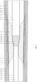
- the method for manufacturing the submarine cable further includes: cutting the first insulating layer 13 of the submarine cable section 1 to obtain a cone surface with a cone angle not greater than 60°, and cutting the second insulating layer 23 of the landing cable section 2 to obtain a cone surface with a cone angle not greater than 60°, as shown in FIG. 1 .
- Such arrangement facilitates subsequent connection of the first insulating layer 13 and the second insulating layer 23.
- an insulating extruder may be used to extrude the material of the insulating recovery layer 33 to cover the conductor shielding recovery layer 32.
- the insulating recovery layer 33 may further be fully crosslinked by a crosslinking machine to ensure that there are no bubbles, pits or cracks on the surface of the insulating recovery layer.
- the thickness, eccentricity, and the presence or absence of visible pores, protrusions or impurities of the insulating recovery layer 33 are detected by an X-ray machine.
- the insulating recovery layer 33 is polished with an abrasive belt to ensure that the surface of the insulating recovery layer 33 is smooth and its outer diameter is larger than that of the first insulating layer 13 and of the second insulating layer 23, and a difference between the outer diameter of the insulating recovery layer 33 and the larger outer diameter in the outer diameter of the first insulating layer 13 and the outer diameter of the second insulating layer 23 is about 5 mm.
- the method for manufacturing the submarine cable further includes:
- first insulation shielding layer 14 and the second insulation shielding layer 24, the first longitudinal water blocking layer 15 and the second longitudinal water blocking layer 25, and the first radial water blocking layer 16 and the second radial water blocking layer 26 can be connected respectively.
- Reference for the materials used for each layer in this embodiment and technical effects thereof may be made to the above-mentioned device embodiments, which are not repeated here.
- the method for manufacturing the submarine cable further includes:
- the first non- metallic sheath layer 17 and the second non- metallic sheath layer 27 can be connected.
- Reference for the materials used for each layer in this embodiment and technical effects thereof may be made to the above-mentioned device embodiments, which are not repeated here.
- the method for manufacturing the submarine cable further includes: Winding a cross-linked polyethylene tape at a junction of the non-metallic sheath recovery layer 37 and the second non-metallic sheath layer 27, and heating the cross-linked polyethylene tape to integrate the cross-linked polyethylene tape, the non-metallic sheath recovery layer 37, and the second non-metallic sheath layer 27.
- Tools such as heat guns may be used in a process of heating the non-metallic sheath material and the cross-linked polyethylene.
- a problem of weak connection occuring when the material of the non-metallic sheath recovery layer 37 is different from that of the first non-metallic sheath layer 17 or of the second non-metallic sheath layer 27 can be solved by the above steps.
- the method for manufacturing the submarine cable provided by the embodiment of the present invention further includes: arranging, with an armoring tool, an armor layer outside the non-metallic sheath recovery layer 37, the first non-metallic sheath layer 17, and the second non-metallic sheath layer 27.
- reference for the material of the armor layer 5 may be made to the above-mentioned device embodiments, which is not repeated here.
- the armoring tool includes a hydraulic cylinder 7, a pressure sensor 8, an inner mould layer 9 and an outer mould layer 10.
- the inner mould layer 9 is located within the outer mould layer 10.
- the hydraulic cylinder 7 is connected with the inner mould layer 9, for controlling the inner mould layer 9 to be tightened or loosened.
- the pressure sensor 8 is in signal connection with the inner mould layer 9 and the hydraulic cylinder 7 respectively for controlling a movement of the hydraulic cylinder 7 according to a pressure on the inner mould layer 9.
- the inner mould layer 9 includes 3 arc-shaped parts 91, and corresponding centers of the 3 arc-shaped parts 91 are at a same point during the tightening and loosening process of the mould. Such arrangement can improve the uniformity of the armor layer 5.
- An inner diameter of the inner mould layer 9 is 2-3 mm larger than the outer diameter of the armor layer 5.
- the submarine cable passes through the inner mould layer 9 gradually.
- a pressure value measured by the pressure sensor 8 exceeds a first tightening force that is set
- the pressure sensor 8 controls an action of the hydraulic cylinder 7, so that the hydraulic cylinder 7 releases the inner mould layer 9 until the pressure value is less than or equal to the first tightening force that is set.
- the pressure sensor 8 controls the action of the hydraulic cylinder 7, and the hydraulic cylinder 7 tightens the inner mould layer 9 until the pressure value is equal to the second tightening force that is set.
- the first tightening force can be a pressure applied to the inner mould layer 9 when the joint 3 passes through the inner mould layer 9
- the second tightening force can be a pressure applied to the inner mould layer 9 when the submarine cable section 1 passes through the inner mould layer 9.
Landscapes
- Engineering & Computer Science (AREA)
- Manufacturing & Machinery (AREA)
- Insulated Conductors (AREA)
Claims (13)
- Unterwasserkabel, umfassend:einen Unterwasserkabelabschnitt (1), der einen ersten Leiter (11) umfasst, wobei der erste Leiter (11) n erste Monofilamentschichten (111) umfasst, die aufeinanderfolgend von innen nach außen in radialer Richtung des Unterwasserkabels angeordnet sind; undeinen Landungskabelabschnitt (2), der einen zweiten Leiter (21) umfasst, wobei der zweite Leiter (21) m zweite Monofilamentschichten (210) umfasst, die aufeinanderfolgend von innen nach außen in radialer Richtung des Unterwasserkabels angeordnet sind, und wobei die m zweiten Monofilamentschichten (210) aufeinanderfolgend von innen nach außen in radialer Richtung des Unterwasserkabels in n zweite Schweißmonofilamentschichten (211) und h zweite gewickelte Monofilamentschichten (212) geteilt sind, wobei m und n beide positive Ganzzahlen sind, und m≥n, h=m-n, h≥2 ;wobei die n ersten Monofilamentschichten (111), von innen nach außen in radialer Richtung des Unterwasserkabels, mit den n zweiten Schweißmonofilamentschichten (211) in einer Eins-zu-Eins-Beziehung verschweißt sind;wobei die h zweiten gewickelten Monofilamentschichten (212), aufeinanderfolgend von innen nach außen in radialer Richtung des Unterwasserkabels, außerhalb einer äußersten Schicht der n ersten Monofilamentschichten (111) gewickelt sind; und für zwei beliebige benachbarte zweite gewickelte Monofilamentschichten (212) ein Wicklungsteil einer zweiten gewickelten Monofilamentschicht (212), die sich außen befindet, einen Wicklungsteil einer zweiten gewickelten Monofilamentschicht (212) bedeckt, die sich innen befindet; wobei sich der Wicklungsteil auf einen Anteil jeder der zweiten gewickelten Monofilamentschichten (212) bezieht, der außerhalb der äußersten Schicht der ersten Monofilamentschichten (111) gewickelt ist; undwobei ein Bereich, in dem die n ersten Monofilamentschichten (111) mit den m zweiten Monofilamentschichten (210) verbunden sind, einen Leiterschweißbereich (31) einer Verbindung (3) bildet;wobei eine Differenz zwischen einer Wicklungssteigung des Wicklungsteils jeder der zweiten gewickelten Monofilamentschichten (212) und einer Verseilungssteigung eines Verseilungsteils jeder der zweiten gewickelten Monofilamentschichten (212) kleiner ist als eine voreingestellte Differenz; undwobei sich der Verseilungsteil auf einen Anteil jeder der zweiten gewickelten Monofilamentschichten (212) bezieht, der außerhalb einer äußersten Schicht der zweiten Schweißmonofilamentschichten (211) verseilt ist, und die voreingestellte Differenz 10 % der Verseilungssteigung des Verseilungsteils jeder der zweiten gewickelten Monofilamentschichten beträgt.
- Unterwasserkabel nach Anspruch 1, wobei für zwei beliebige benachbarte zweite Schweißmonofilamentschichten (211) eine zweite Schweißmonofilamentschicht (211), die sich außen befindet, einen sekundären Schweißbereich (311) zwischen einer zweiten Schweißmonofilamentschicht (211), die sich innen befindet, und einer entsprechenden ersten Monofilamentschicht (111) bedeckt;wobei eine innerste Schicht der zweiten gewickelten Monofilamentschichten (212) einen sekundären Schweißbereich (311) zwischen der äußersten Schicht der ersten Monofilamentschichten (111) und der äußersten Schicht der zweiten Schweißmonofilamentschichten (211) bedeckt; undwobei der sekundäre Schweißbereich (311) ein Bereich ist, in dem die ersten Monofilamentschichten (111) mit den zweiten Monofilamentschichten (210) verschweißt sind.
- Unterwasserkabel nach Anspruch 2, wobei der Unterwasserkabelabschnitt (1) ferner eine erste Leiterabschirmungsschicht (12) umfasst, und die erste Leiterabschirmungsschicht (12) einen Teil des ersten Leiters (11) bedeckt;wobei der Landungskabelabschnitt (2) ferner eine zweite Leiterabschirmungsschicht (22) umfasst, und die zweite Leiterabschirmungsschicht (22) einen Teil des zweiten Leiters (21) bedeckt; undwobei die Verbindung (3) ferner eine Leiterabschirmungs-Rückgewinnungsschicht (32) umfasst, wobei die Leiterabschirmungs-Rückgewinnungsschicht (32) einen Teil des ersten Leiters (11), einen Teil des zweiten Leiters (21) und den Leiterschweißbereich (31) bedeckt, und die Leiterabschirmungs-Rückgewinnungsschicht (32) mit einem Ende mit der ersten Leiterabschirmungsschicht (12) verbunden ist und mit dem anderen Ende mit der zweiten Leiterabschirmungsschicht (22) verbunden ist.
- Unterwasserkabel nach Anspruch 3, wobei der Unterwasserkabelabschnitt (1) ferner eine erste Isolierschicht (13) umfasst, und die erste Isolierschicht (13) die erste Leiterabschirmungsschicht (12) bedeckt;wobei der Landungskabelabschnitt (2) ferner eine zweite Isolierschicht (23) umfasst, und die zweite Isolierschicht (23) die zweite Leiterabschirmungsschicht (22) bedeckt; undwobei die Verbindung (3) ferner eine isolierende Rückgewinnungsschicht (33) umfasst, wobei die isolierende Rückgewinnungsschicht (33) die Leiterabschirmungs-Rückgewinnungsschicht (32) bedeckt, und die isolierende Rückgewinnungsschicht (33) mit einem Ende mit der ersten Isolierschicht (13) verbunden ist und mit dem anderen Ende mit der zweiten Isolierschicht (23) verbunden ist.
- Unterwasserkabel nach Anspruch 4, wobei der Unterwasserkabelabschnitt (1) ferner eine erste Isolierabschirmungsschicht (14) umfasst, und die erste Isolierabschirmungsschicht (14) die erste Isolierschicht (13) bedeckt;wobei der Landungskabelabschnitt (2) ferner eine zweite Isolierabschirmungsschicht (24) umfasst, und die zweite Isolierabschirmungsschicht (24) die zweite Isolierschicht (23) bedeckt; undwobei die Verbindung (3) ferner eine Isolierabschirmungs-Rückgewinnungsschicht (34) umfasst, wobei die Isolierabschirmungs-Rückgewinnungsschicht (34) die isolierende Rückgewinnungsschicht (33) bedeckt, und die Isolierabschirmungs-Rückgewinnungsschicht (34) mit einem Ende mit der ersten Isolierabschirmungsschicht (14) verbunden ist und mit dem anderen Ende mit der zweiten Isolierabschirmungsschicht (24) verbunden ist.
- Unterwasserkabel nach Anspruch 5, wobei der Unterwasserkabelabschnitt (1) ferner eine erste längslaufende wasserblockierende Schicht (15) umfasst, und die erste längslaufende wasserblockierende Schicht (15) einen Teil der ersten Isolierabschirmungsschicht (14) bedeckt;wobei der Landungskabelabschnitt (2) ferner eine zweite längslaufende wasserblockierende Schicht (25) umfasst, und die zweite längslaufende wasserblockierende Schicht (25) einen Teil der zweiten Isolierabschirmungsschicht (24) bedeckt; undwobei die Verbindung (3) ferner eine längslaufende wasserblockierende Rückgewinnungsschicht (35) umfasst, wobei die längslaufende wasserblockierende Rückgewinnungsschicht (35) einen Teil der ersten Isolierabschirmungsschicht (14), einen Teil der zweiten Isolierabschirmungsschicht (24) und die Isolierabschirmungs-Rückgewinnungsschicht (34) bedeckt, und wobei die längslaufende wasserblockierende Rückgewinnungsschicht (35) mit einem Ende mit der ersten längslaufenden wasserblockierenden Schicht (15) verbunden ist und mit dem anderen Ende mit der zweiten längslaufenden wasserblockierenden Schicht (25) verbunden ist;optional, wobei der Unterwasserkabelabschnitt (1) ferner eine erste radiale wasserblockierende Schicht (16) umfasst, und die erste radiale wasserblockierende Schicht (16) einen Teil der ersten längslaufenden wasserblockierenden Schicht (15) bedeckt;wobei der Landungskabelabschnitt (2) ferner eine zweite radiale wasserblockierende Schicht (26) umfasst, und die zweite radiale wasserblockierende Schicht (26) einen Teil der zweiten längslaufenden wasserblockierenden Schicht (25) bedeckt; undwobei die Verbindung (3) ferner eine radiale wasserblockierende Rückgewinnungsschicht (36) umfasst, wobei die radiale wasserblockierende Rückgewinnungsschicht (36) einen Teil der ersten längslaufenden wasserblockierenden Schicht (15), einen Teil der zweiten längslaufenden wasserblockierenden Schicht (25) und die längslaufende wasserblockierende Rückgewinnungsschicht (35) bedeckt, und die radiale wasserblockierende Rückgewinnungsschicht (36) mit einem Ende mit der ersten radialen wasserblockierenden Schicht (16) verbunden ist und mit dem anderen Ende mit der zweiten radialen wasserblockierenden Schicht (26) verbunden ist;optional, wobei der Unterwasserkabelabschnitt (1) ferner eine erste nicht-metallische Mantelschicht (17) umfasst, und die erste nicht-metallische Mantelschicht (17) einen Teil der ersten radialen wasserblockierenden Schicht (16) bedeckt;wobei der Landungskabelabschnitt (2) ferner eine zweite nicht-metallische Mantelschicht (27) umfasst, und die zweite nicht-metallische Mantelschicht (27) einen Teil der zweiten radialen wasserblockierenden Schicht (26) bedeckt; undwobei die Verbindung (3) ferner eine nicht-metallische Mantelrückgewinnungsschicht (37) umfasst, und die nicht-metallische Mantelrückgewinnungsschicht (37) einen Teil der ersten radialen wasserblockierenden Schicht (16), einen Teil der zweiten radialen wasserblockierenden Schicht (26) und die radiale wasserblockierende Rückgewinnungsschicht (36) bedeckt, und die nicht-metallische Mantelrückgewinnungsschicht (37) mit einem Ende mit der ersten nicht-metallischen Mantelschicht (17) verbunden ist und mit dem anderen Ende mit der zweiten nicht-metallischen Mantelschicht (27) verbunden ist; undoptional, wobei das Unterwasserkabel ferner eine innere Panzerungspolsterschicht (4), eine Panzerungsschicht (5) und eine äußere Panzerungsüberzugsschicht (6) umfasst, und die innere Panzerungspolsterschicht (4) die erste nicht-metallische Mantelschicht (17), die zweite nicht-metallische Mantelschicht (27) und die nicht-metallische Mantelrückgewinnungsschicht (37) bedeckt; undwobei die Panzerungsschicht (5) die innere Panzerungspolsterschicht (4) bedeckt, und die äußere Panzerungsüberzugsschicht (6) die Panzerungsschicht (5) bedeckt.
- Verfahren zur Herstellung eines Unterwasserkabels, umfassend:Bereitstellen eines Unterwasserkabelabschnitts (1) und eines Landungskabelabschnitts (2), wobei der Unterwasserkabelabschnitt (1) einen ersten Leiter (11) umfasst, und der erste Leiter (11) n erste Monofilamentschichten (111) umfasst, die von innen nach außen in radialer Richtung des Unterwasserkabels angeordnet sind; und der Landungskabelabschnitt (2) einen zweiten Leiter (21) umfasst, wobei der zweite Leiter (21) m zweite Monofilamentschichten (210) umfasst, die aufeinanderfolgend von innen nach außen in radialer Richtung des Unterwasserkabels angeordnet sind, und die m zweiten Monofilamentschichten (210) aufeinanderfolgend von innen nach außen in radialer Richtung des Unterwasserkabels in n zweite Schweißmonofilamentschichten (211) und h zweite gewickelte Monofilamentschichten (212) geteilt sind, wobei m und n beide positive Ganzzahlen sind, und m≥n, h=m-n, h≥2;Verschweißen, aufeinanderfolgend von innen nach außen in radialer Richtung des Unterwasserkabels, der n ersten Monofilamentschichten (111) mit den n zweiten Schweißmonofilamentschichten (211) in einer Eins-zu-Eins-Beziehung; undWickeln, aufeinanderfolgend von innen nach außen in radialer Richtung des Unterwasserkabels, der h zweiten gewickelten Monofilamentschichten (212) außerhalb einer äußersten Schicht der n ersten Monofilamentschichten (111), wobei für zwei beliebige benachbarte zweite gewickelte Monofilamentschichten (212) ein Wicklungsteil einer zweiten gewickelten Monofilamentschicht (212), die sich außen befindet, einen Wicklungsteil einer zweiten gewickelten Monofilamentschicht (212) bedeckt, die sich innen befindet; wobei sich der Wicklungsteil auf einen Anteil jeder der zweiten gewickelten Monofilamentschichten (212) bezieht, der außerhalb der äußersten Schicht der ersten Monofilamentschichten (111) gewickelt ist; so dass ein Bereich, in dem die n ersten Monofilamentschichten (111) mit den m zweiten Monofilamentschichten (210) verbunden sind, einen Leiterschweißbereich (31) einer Verbindung (3) bildet;wobei in einem Schritt des Wickelns, aufeinanderfolgend von innen nach außen, der h zweiten gewickelten Monofilamentschichten (212) außerhalb der äußersten Schicht der n ersten Monofilamentschichten (111), eine Differenz zwischen einer Wicklungssteigung des Wicklungsteils jeder der zweiten gewickelten Monofilamentschichten (212) und einer Verseilungssteigung eines Verseilungsteils jeder der zweiten gewickelten Monofilamentschichten (212) kleiner ist als eine voreingestellte Differenz; undwobei sich der Verseilungsteil auf einen Anteil jeder der zweiten gewickelten Monofilamentschichten (212) bezieht, der außerhalb einer äußersten Schicht der zweiten Schweißmonofilamentschichten (211) verseilt ist, und die voreingestellte Differenz 10 % der Verseilungssteigung des Verseilungsteils jeder der zweiten gewickelten Monofilamentschichten beträgt.
- Verfahren zur Herstellung des Unterwasserkabels nach Anspruch 7, wobei ein Schritt des Verschweißens der n ersten Monofilamentschichten (111) mit den n zweiten Schweißmonofilamentschichten (211) in einer Eins-zu-Eins-Beziehung ferner umfasst:Bedecken, durch eine zweite Schweißmonofilamentschicht (211), die sich außen befindet, eines sekundären Schweißbereichs (311) zwischen einer zweiten Schweißmonofilamentschicht (211), die sich innen befindet, und einer entsprechenden ersten Monofilamentschicht (111), wobei der sekundäre Schweißbereich (311) ein Bereich ist, in dem die ersten Monofilamentschichten (111) mit den zweiten Monofilamentschichten (210) verschweißt sind; undwobei in dem Schritt des Wickelns, aufeinanderfolgend von innen nach außen in radialer Richtung des Unterwasserkabels, der h zweiten gewickelten Monofilamentschichten (212) außerhalb der äußersten Schicht der n ersten Monofilamentschichten (111), eine innerste Schicht der zweiten gewickelten Monofilamentschichten (212) einen sekundären Schweißbereich (311) zwischen der äußersten Schicht der ersten Monofilamentschichten (111) und der äußersten Schicht der zweiten Schweißmonofilamentschichten (211) bedeckt; undoptional wobei der Schritt des Wickelns, aufeinanderfolgend von innen nach außen in radialer Richtung des Unterwasserkabels, der h zweiten gewickelten Monofilamentschichten (212) außerhalb der äußersten Schicht der n ersten Monofilamentschichten (111) ferner umfasst:
Verschweißen eines Wicklungsendes des Wicklungsteils jeder der zweiten gewickelten Monofilamentschichten (212) mit der äußersten Schicht der ersten Monofilamentschichten (111), und Durchführen eines Poliervorgangs an einem Schweißbereich zwischen dem Wicklungsende und der äußersten Schicht der ersten Monofilamentschichten (111), so dass eine Verbindung zwischen dem Wicklungsende und der äußersten Schicht der ersten Monofilamentschichten (111) fest und glatt ist. - Verfahren zur Herstellung des Unterwasserkabels nach Anspruch 8, wobei nach einem Schritt des Bildens des Leiterschweißbereichs (31) das Verfahren zur Herstellung des Unterwasserkabels ferner umfasst:
Bedecken, durch Wickeln oder Strangpressen mit einem gleichen Material wie eine Leiterabschirmungsschicht, des Leiterschweißbereichs (31) und eines freiliegenden Anteils des ersten Leiters (11) und eines freiliegenden Anteils des zweiten Leiters (21), um eine Leiterabschirmungs-Rückgewinnungsschicht (32) zu bilden, und Machen, dass die Leiterabschirmungs-Rückgewinnungsschicht (32) mit einem Ende mit einer ersten Leiterabschirmungsschicht (12) des Unterwasserkabelabschnitts (1) verbunden ist und mit dem anderen Ende mit einer zweiten Leiterabschirmungsschicht (22) des Landungskabelabschnitts (2) verbunden ist. - Verfahren zur Herstellung des Unterwasserkabels nach Anspruch 9, wobei nach einem Schritt des Bildens der Leiterabschirmungs-Rückgewinnungsschicht (32) das Verfahren zur Herstellung des Unterwasserkabels ferner umfasst:Schneiden einer ersten Isolierschicht (13) des Unterwasserkabelabschnitts (1), um eine Konusoberfläche mit einem Konuswinkel von nicht mehr als 60° zu erhalten, und Schneiden einer zweiten Isolierschicht (23) des Landungskabelabschnitts (2), um eine Konusoberfläche mit einem Konuswinkel von nicht mehr als 60° zu erhalten; undBedecken, durch Strangpressen mit einem gleichen Material wie die erste Isolierschicht (13) und die zweite Isolierschicht (23), der Leiterabschirmungs-Rückgewinnungsschicht (32), um eine isolierende Rückgewinnungsschicht (33) zu bilden, und Machen, dass die isolierende Rückgewinnungsschicht (33) mit einem Ende mit der ersten Isolierschicht (13) verbunden ist und mit dem anderen Ende mit der zweiten Isolierschicht (23) verbunden ist.
- Verfahren zur Herstellung des Unterwasserkabels nach Anspruch 10, wobei nach einem Schritt des Bildens der isolierenden Rückgewinnungsschicht (33) das Verfahren zur Herstellung des Unterwasserkabels ferner umfasst:Bedecken, mit einem gleichen Material wie die erste Isolierabschirmungsschicht (14) des Unterwasserkabelabschnitts (1) und eine zweite Isolierabschirmungsschicht (24) des Landungskabelabschnitts (2), die isolierende Rückgewinnungsschicht (33), um eine Isolierabschirmungs-Rückgewinnungsschicht (34) zu bilden, und Machen, dass die Isolierabschirmungs-Rückgewinnungsschicht (34) mit einem Ende mit der ersten Isolierabschirmungsschicht (14) verbunden ist und mit dem anderen Ende mit der zweiten Isolierabschirmungsschicht (24) verbunden ist;Bedecken, mit einem gleichen Material wie eine erste längslaufende wasserblockierende Schicht (15) des Unterwasserkabelabschnitts (1) und eine zweite längslaufende wasserblockierende Schicht (25) des Landungskabelabschnitts (2), der Isolierabschirmungs-Rückgewinnungsschicht (34), um eine längslaufende wasserblockierende Rückgewinnungsschicht (35) zu bilden, und Machen, dass die längslaufende wasserblockierende Rückgewinnungsschicht (35) mit einem Ende mit der ersten längslaufenden wasserblockierenden Schicht (15) verbunden ist und mit dem anderen Ende mit der zweiten längslaufenden wasserblockierenden Schicht (25) verbunden ist; undBedecken, mit einem gleichen Material wie eine erste radiale wasserblockierende Schicht (16) des Unterwasserkabelabschnitts (1) und eine zweite radiale wasserblockierende Schicht (26) des Landungskabelabschnitts (2), der längslaufenden wasserblockierenden Rückgewinnungsschicht (35), um eine radiale wasserblockierende Rückgewinnungsschicht (36) zu bilden, und Machen, dass die radiale wasserblockierende Rückgewinnungsschicht (36) mit einem Ende mit der ersten radialen wasserblockierenden Schicht (16) verbunden ist und mit dem anderen Ende mit der zweiten radialen wasserblockierenden Schicht (26) verbunden ist.
- Verfahren zur Herstellung des Unterwasserkabels nach Anspruch 11, wobei nach einem Schritt des Bildens der radialen wasserblockierenden Rückgewinnungsschicht (36) das Verfahren zur Herstellung des Unterwasserkabels ferner umfasst:wenn ein Material einer ersten nicht-metallischen Mantelschicht (17) des Unterwasserkabelabschnitts (1) dasselbe ist wie das einer zweiten nicht-metallischen Mantelschicht (27) des Landungskabelabschnitts (2), Bedecken, mit einem nicht-metallischen Mantelmaterial, das dasselbe ist wie das der ersten nicht-metallischen Mantelschicht (17) und der zweiten nicht-metallischen Mantelschicht (27), der radialen wasserblockierenden Rückgewinnungsschicht (36), und Erwärmen des nicht-metallischen Mantelmaterials, um eine nicht-metallische Mantelrückgewinnungsschicht (37) mit der nicht-metallischen Mantelrückgewinnungsschicht (37) zu bilden, wobei die erste nicht-metallische Mantelschicht (17) und die zweite nicht-metallische Mantelschicht (27) integriert sind; undwenn sich das Material der ersten nicht-metallischen Mantelschicht (17) des Unterwasserkabelabschnitts (1) von dem der zweiten nicht-metallischen Mantelschicht (27) des Landungskabelabschnitts (2) unterscheidet, Bedecken, mit einem nicht-metallischen Mantelmaterial, das dasselbe ist wie das der ersten nicht-metallischen Mantelschicht (17) oder der zweiten nicht-metallischen Mantelschicht (27), der radialen wasserblockierenden Rückgewinnungsschicht (36), und Erwärmen des nicht-metallischen Mantelmaterials, um eine nicht-metallische Mantelrückgewinnungsschicht (37) mit der nicht-metallischen Mantelrückgewinnungsschicht (37) zu bilden, wobei die erste nicht-metallische Mantelschicht (17) und die zweite nicht-metallische Mantelschicht (27) integriert sind.
- Verfahren zur Herstellung des Unterwasserkabels nach Anspruch 12, wobei nach einem Schritt, bei dem sich das Material der ersten nicht-metallischen Mantelschicht (17) des Unterwasserkabelabschnitts (1) von dem der zweiten nicht-metallischen Mantelschicht (27) des Landungskabelabschnitts (2) unterscheidet, Bedecken, durch Strangpressen mit dem nicht-metallischen Mantelmaterial, das dasselbe ist wie das der ersten nicht-metallischen Mantelschicht (17) oder der zweiten nicht-metallischen Mantelschicht (27), der radialen wasserblockierenden Rückgewinnungsschicht (36), und Erwärmen des nicht-metallischen Mantelmaterials, um die nicht-metallische Mantelrückgewinnungsschicht (37) zu bilden, wobei das Verfahren zur Herstellung des Unterwasserkabels ferner umfasst:wenn das nicht-metallische Mantelmaterial dasselbe ist wie das Material der ersten nicht-metallischen Mantelschicht (17), Wickeln eines vernetzten Polyethylenbandes an einer Verbindungsstelle zwischen der nicht-metallischen Mantelrückgewinnungsschicht (37) und der zweiten nicht-metallischen Mantelschicht (27), und Erwärmen des vernetzten Polyethylenbandes, um das vernetzte Polyethylenband, die nicht-metallische Mantelrückgewinnungsschicht (37) und die zweite nicht-metallische Mantelschicht (27) zu integrieren; undwenn das nicht-metallische Mantelmaterial dasselbe ist wie das Material der zweiten nicht-metallischen Mantelschicht (27), Wickeln eines vernetzten Polyethylenbandes an einer Verbindungsstelle zwischen der nicht-metallischen Mantelrückgewinnungsschicht (37) und der ersten nicht-metallischen Mantelschicht (17), und Erwärmen des vernetzten Polyethylenbandes, um das vernetzte Polyethylenband, die nicht-metallische Mantelrückgewinnungsschicht (37) und die erste nicht-metallische Mantelschicht (17) zu integrieren;wobei optional nach einem Schritt des Bildens der nicht-metallischen Mantelrückgewinnungsschicht (37), das Verfahren zur Herstellung des Unterwasserkabels ferner umfasst:Anordnen, durch Verwenden eines Panzerungswerkzeugs, einer Panzerungsschicht (5) außerhalb der nicht-metallischen Mantelrückgewinnungsschicht (37), der ersten nicht-metallischen Mantelschicht (17) und der zweiten nicht-metallischen Mantelschicht (27);wobei das Panzerungswerkzeug einen Hydraulikzylinder (7), einen Drucksensor (8), eine innere Formschicht (9) und eine äußere Formschicht (10) umfasst, wobei die innere Formschicht (9) innerhalb der äußeren Formschicht (10) angeordnet ist, wobei der Hydraulikzylinder (7) mit der inneren Formschicht (9) verbunden ist, um ein Anziehen oder Lösen der inneren Formschicht (9) zu steuern, und der Drucksensor (8) in Signalverbindung mit jeweils der inneren Formschicht (9) und dem Hydraulikzylinder (7) steht, um eine Bewegung des Hydraulikzylinders (7) entsprechend einem Druck auf die innere Formschicht (9) zu steuern.
Applications Claiming Priority (2)
| Application Number | Priority Date | Filing Date | Title |
|---|---|---|---|
| CN202011568968.6A CN112735635B (zh) | 2020-12-25 | 2020-12-25 | 海底电缆及其制造方法 |
| PCT/CN2021/087591 WO2022134392A1 (zh) | 2020-12-25 | 2021-04-15 | 海底电缆及其制造方法 |
Publications (4)
| Publication Number | Publication Date |
|---|---|
| EP4199007A1 EP4199007A1 (de) | 2023-06-21 |
| EP4199007A4 EP4199007A4 (de) | 2024-03-13 |
| EP4199007B1 true EP4199007B1 (de) | 2025-01-29 |
| EP4199007C0 EP4199007C0 (de) | 2025-01-29 |
Family
ID=75616714
Family Applications (1)
| Application Number | Title | Priority Date | Filing Date |
|---|---|---|---|
| EP21908404.3A Active EP4199007B1 (de) | 2020-12-25 | 2021-04-15 | Unterwasserkabel und herstellungsverfahren dafür |
Country Status (5)
| Country | Link |
|---|---|
| EP (1) | EP4199007B1 (de) |
| CN (1) | CN112735635B (de) |
| ES (1) | ES3015477T3 (de) |
| PL (1) | PL4199007T3 (de) |
| WO (1) | WO2022134392A1 (de) |
Families Citing this family (6)
| Publication number | Priority date | Publication date | Assignee | Title |
|---|---|---|---|---|
| CN113380464B (zh) * | 2021-06-19 | 2022-07-29 | 中航宝胜海洋工程电缆有限公司 | 一种节本增效用海底电缆导体加工方法 |
| CN113782263B (zh) * | 2021-09-14 | 2024-03-26 | 中天科技海缆股份有限公司 | 海底电缆及制备方法 |
| CN113782264B (zh) * | 2021-09-14 | 2022-11-15 | 中天科技海缆股份有限公司 | 海底电缆 |
| CN114005577B (zh) * | 2021-11-30 | 2022-08-30 | 中天科技海缆股份有限公司 | 海底电缆异质导体及其加工方法、海底电缆及其制备方法 |
| CN114700751B (zh) * | 2022-03-28 | 2023-04-07 | 宁波东方电缆股份有限公司 | 一种导体变径对接焊接工艺 |
| CN116978611B (zh) * | 2023-08-24 | 2025-06-24 | 中天科技海缆股份有限公司 | 海底电缆及海底电缆的制造方法 |
Citations (1)
| Publication number | Priority date | Publication date | Assignee | Title |
|---|---|---|---|---|
| JP2001112139A (ja) * | 1999-10-04 | 2001-04-20 | Electric Power Dev Co Ltd | 海底ケーブルの接続方法 |
Family Cites Families (4)
| Publication number | Priority date | Publication date | Assignee | Title |
|---|---|---|---|---|
| JP5554168B2 (ja) * | 2010-07-13 | 2014-07-23 | 株式会社ビスキャス | 海底ケーブル |
| CN102664380B (zh) * | 2012-04-19 | 2015-01-07 | 中天科技海缆有限公司 | 220kV交联聚乙烯海底电缆软接头及其制作方法 |
| JP6294771B2 (ja) * | 2014-06-24 | 2018-03-14 | 古河電気工業株式会社 | 外装鉄線の接続部材、外装鉄線の接続構造および接続方法 |
| CN110993154A (zh) * | 2019-12-26 | 2020-04-10 | 中天科技海缆有限公司 | 一种超高压海缆软接头及其制作方法 |
-
2020
- 2020-12-25 CN CN202011568968.6A patent/CN112735635B/zh active Active
-
2021
- 2021-04-15 WO PCT/CN2021/087591 patent/WO2022134392A1/zh not_active Ceased
- 2021-04-15 PL PL21908404.3T patent/PL4199007T3/pl unknown
- 2021-04-15 EP EP21908404.3A patent/EP4199007B1/de active Active
- 2021-04-15 ES ES21908404T patent/ES3015477T3/es active Active
Patent Citations (1)
| Publication number | Priority date | Publication date | Assignee | Title |
|---|---|---|---|---|
| JP2001112139A (ja) * | 1999-10-04 | 2001-04-20 | Electric Power Dev Co Ltd | 海底ケーブルの接続方法 |
Also Published As
| Publication number | Publication date |
|---|---|
| CN112735635A (zh) | 2021-04-30 |
| PL4199007T3 (pl) | 2025-04-14 |
| WO2022134392A1 (zh) | 2022-06-30 |
| ES3015477T3 (en) | 2025-05-05 |
| EP4199007A4 (de) | 2024-03-13 |
| CN112735635B (zh) | 2021-10-08 |
| EP4199007A1 (de) | 2023-06-21 |
| EP4199007C0 (de) | 2025-01-29 |
Similar Documents
| Publication | Publication Date | Title |
|---|---|---|
| EP4199007B1 (de) | Unterwasserkabel und herstellungsverfahren dafür | |
| EP3623854B1 (de) | Optische kabel für raue umgebungen | |
| RU2087015C1 (ru) | Подводное устройство большой протяженности с волоконно-оптическими элементами (варианты) | |
| US10056171B2 (en) | Submarine cable and multilayer tape for impermeable layer of same | |
| US4081602A (en) | Self-supporting cable | |
| US20160301198A1 (en) | Undersea cable, undersea cable installation structure, and method for installing undersea cable | |
| GB2043936A (en) | Undersea optical fibre telecommunications cable and a method and apparatus for manufacture thereof | |
| EP3803911B1 (de) | Hochspannungsstromkabel mit ermüdungsbeständiger wassersperre | |
| KR20200047419A (ko) | 보강된 해저 전력 케이블 | |
| EP4174879A1 (de) | Unterwasserkabel | |
| EP3139443A1 (de) | Elektrisches hochspannungskabel | |
| EP4629267A1 (de) | Unterwasserkabel | |
| US20230133613A1 (en) | Intermediate connection structure of power cable | |
| WO2013126082A1 (en) | A multicore electrical cable and method of manufacture | |
| JP2019512859A (ja) | 直流海底ケーブル | |
| EP3885120A1 (de) | Unterwasserstromkabel für grosse wassertiefe und herstellungsverfahren für ein solches unterwasserstromkabel | |
| CN113782263A (zh) | 海底电缆及制备方法 | |
| WO2013033305A1 (en) | Cable and umbilical | |
| EP3930129A1 (de) | Zwischenverbindungsstruktur eines stromkabels | |
| CN115762876B (zh) | 铠装海缆及铠装海缆制造方法 | |
| US12567519B2 (en) | Power cable system having different conductor connecting part, and power cable connection method having different conductors | |
| CN117878813A (zh) | 海缆入舱密封组件、光电复合缆及海缆入舱的方法 | |
| US4064358A (en) | Termination for connecting a submarine coaxial cable to a submergible housing | |
| US3144499A (en) | Insulating structure for high voltage power cables | |
| US4833275A (en) | Flexible splice for an impregnated paper submarine cable |
Legal Events
| Date | Code | Title | Description |
|---|---|---|---|
| STAA | Information on the status of an ep patent application or granted ep patent |
Free format text: STATUS: THE INTERNATIONAL PUBLICATION HAS BEEN MADE |
|
| PUAI | Public reference made under article 153(3) epc to a published international application that has entered the european phase |
Free format text: ORIGINAL CODE: 0009012 |
|
| STAA | Information on the status of an ep patent application or granted ep patent |
Free format text: STATUS: REQUEST FOR EXAMINATION WAS MADE |
|
| 17P | Request for examination filed |
Effective date: 20230315 |
|
| AK | Designated contracting states |
Kind code of ref document: A1 Designated state(s): AL AT BE BG CH CY CZ DE DK EE ES FI FR GB GR HR HU IE IS IT LI LT LU LV MC MK MT NL NO PL PT RO RS SE SI SK SM TR |
|
| A4 | Supplementary search report drawn up and despatched |
Effective date: 20240209 |
|
| RIC1 | Information provided on ipc code assigned before grant |
Ipc: H01B 13/00 20060101ALI20240205BHEP Ipc: H01B 9/02 20060101ALI20240205BHEP Ipc: H01B 9/00 20060101ALI20240205BHEP Ipc: H01B 7/14 20060101ALI20240205BHEP Ipc: H01B 7/04 20060101ALI20240205BHEP Ipc: H01B 7/00 20060101AFI20240205BHEP |
|
| DAV | Request for validation of the european patent (deleted) | ||
| DAX | Request for extension of the european patent (deleted) | ||
| STAA | Information on the status of an ep patent application or granted ep patent |
Free format text: STATUS: EXAMINATION IS IN PROGRESS |
|
| 17Q | First examination report despatched |
Effective date: 20240612 |
|
| 17Q | First examination report despatched |
Effective date: 20240625 |
|
| RIN1 | Information on inventor provided before grant (corrected) |
Inventor name: FANG, JINGJING Inventor name: WU, JINGCHAO Inventor name: WENG, JIAN Inventor name: WANG, HAIYANG Inventor name: ZHAO, YOULIN Inventor name: XUE, JIANLIN Inventor name: ZHANG, HONGLIANG Inventor name: HU, MING Inventor name: WANG, LIYUAN |
|
| GRAP | Despatch of communication of intention to grant a patent |
Free format text: ORIGINAL CODE: EPIDOSNIGR1 |
|
| STAA | Information on the status of an ep patent application or granted ep patent |
Free format text: STATUS: GRANT OF PATENT IS INTENDED |
|
| INTG | Intention to grant announced |
Effective date: 20241119 |
|
| GRAS | Grant fee paid |
Free format text: ORIGINAL CODE: EPIDOSNIGR3 |
|
| GRAA | (expected) grant |
Free format text: ORIGINAL CODE: 0009210 |
|
| STAA | Information on the status of an ep patent application or granted ep patent |
Free format text: STATUS: THE PATENT HAS BEEN GRANTED |
|
| AK | Designated contracting states |
Kind code of ref document: B1 Designated state(s): AL AT BE BG CH CY CZ DE DK EE ES FI FR GB GR HR HU IE IS IT LI LT LU LV MC MK MT NL NO PL PT RO RS SE SI SK SM TR |
|
| REG | Reference to a national code |
Ref country code: GB Ref legal event code: FG4D |
|
| REG | Reference to a national code |
Ref country code: CH Ref legal event code: EP |
|
| REG | Reference to a national code |
Ref country code: DE Ref legal event code: R096 Ref document number: 602021025707 Country of ref document: DE |
|
| REG | Reference to a national code |
Ref country code: IE Ref legal event code: FG4D |
|
| U01 | Request for unitary effect filed |
Effective date: 20250217 |
|
| U07 | Unitary effect registered |
Designated state(s): AT BE BG DE DK EE FI FR IT LT LU LV MT NL PT RO SE SI Effective date: 20250224 |
|
| REG | Reference to a national code |
Ref country code: GR Ref legal event code: EP Ref document number: 20250400506 Country of ref document: GR Effective date: 20250409 |
|
| U20 | Renewal fee for the european patent with unitary effect paid |
Year of fee payment: 5 Effective date: 20250424 |
|
| PG25 | Lapsed in a contracting state [announced via postgrant information from national office to epo] |
Ref country code: RS Free format text: LAPSE BECAUSE OF FAILURE TO SUBMIT A TRANSLATION OF THE DESCRIPTION OR TO PAY THE FEE WITHIN THE PRESCRIBED TIME-LIMIT Effective date: 20250429 |
|
| PGFP | Annual fee paid to national office [announced via postgrant information from national office to epo] |
Ref country code: PL Payment date: 20250402 Year of fee payment: 5 |
|
| PGFP | Annual fee paid to national office [announced via postgrant information from national office to epo] |
Ref country code: ES Payment date: 20250519 Year of fee payment: 5 |
|
| PGFP | Annual fee paid to national office [announced via postgrant information from national office to epo] |
Ref country code: IS Payment date: 20250423 Year of fee payment: 5 Ref country code: NO Payment date: 20250422 Year of fee payment: 5 |
|
| PG25 | Lapsed in a contracting state [announced via postgrant information from national office to epo] |
Ref country code: HR Free format text: LAPSE BECAUSE OF FAILURE TO SUBMIT A TRANSLATION OF THE DESCRIPTION OR TO PAY THE FEE WITHIN THE PRESCRIBED TIME-LIMIT Effective date: 20250129 |
|
| PGFP | Annual fee paid to national office [announced via postgrant information from national office to epo] |
Ref country code: GR Payment date: 20250416 Year of fee payment: 5 |
|
| PGFP | Annual fee paid to national office [announced via postgrant information from national office to epo] |
Ref country code: IE Payment date: 20250428 Year of fee payment: 5 |
|
| PG25 | Lapsed in a contracting state [announced via postgrant information from national office to epo] |
Ref country code: SM Free format text: LAPSE BECAUSE OF FAILURE TO SUBMIT A TRANSLATION OF THE DESCRIPTION OR TO PAY THE FEE WITHIN THE PRESCRIBED TIME-LIMIT Effective date: 20250129 |
|
| PG25 | Lapsed in a contracting state [announced via postgrant information from national office to epo] |
Ref country code: CZ Free format text: LAPSE BECAUSE OF FAILURE TO SUBMIT A TRANSLATION OF THE DESCRIPTION OR TO PAY THE FEE WITHIN THE PRESCRIBED TIME-LIMIT Effective date: 20250129 |
|
| PG25 | Lapsed in a contracting state [announced via postgrant information from national office to epo] |
Ref country code: SK Free format text: LAPSE BECAUSE OF FAILURE TO SUBMIT A TRANSLATION OF THE DESCRIPTION OR TO PAY THE FEE WITHIN THE PRESCRIBED TIME-LIMIT Effective date: 20250129 |
|
| REG | Reference to a national code |
Ref country code: CH Ref legal event code: H13 Free format text: ST27 STATUS EVENT CODE: U-0-0-H10-H13 (AS PROVIDED BY THE NATIONAL OFFICE) Effective date: 20251125 |
|
| PLBE | No opposition filed within time limit |
Free format text: ORIGINAL CODE: 0009261 |
|
| STAA | Information on the status of an ep patent application or granted ep patent |
Free format text: STATUS: NO OPPOSITION FILED WITHIN TIME LIMIT |
|
| PG25 | Lapsed in a contracting state [announced via postgrant information from national office to epo] |
Ref country code: MC Free format text: LAPSE BECAUSE OF FAILURE TO SUBMIT A TRANSLATION OF THE DESCRIPTION OR TO PAY THE FEE WITHIN THE PRESCRIBED TIME-LIMIT Effective date: 20250129 |
|
| 26N | No opposition filed |
Effective date: 20251030 |
|
| PG25 | Lapsed in a contracting state [announced via postgrant information from national office to epo] |
Ref country code: CH Free format text: LAPSE BECAUSE OF NON-PAYMENT OF DUE FEES Effective date: 20250430 |
|
| PGFP | Annual fee paid to national office [announced via postgrant information from national office to epo] |
Ref country code: GB Payment date: 20260324 Year of fee payment: 6 |