EP4198684A1 - Circuit board module and release component - Google Patents
Circuit board module and release component Download PDFInfo
- Publication number
- EP4198684A1 EP4198684A1 EP22206903.1A EP22206903A EP4198684A1 EP 4198684 A1 EP4198684 A1 EP 4198684A1 EP 22206903 A EP22206903 A EP 22206903A EP 4198684 A1 EP4198684 A1 EP 4198684A1
- Authority
- EP
- European Patent Office
- Prior art keywords
- section
- rotating button
- circuit board
- linking member
- button
- Prior art date
- Legal status (The legal status is an assumption and is not a legal conclusion. Google has not performed a legal analysis and makes no representation as to the accuracy of the status listed.)
- Granted
Links
Images



Classifications
-
- H—ELECTRICITY
- H01—ELECTRIC ELEMENTS
- H01R—ELECTRICALLY-CONDUCTIVE CONNECTIONS; STRUCTURAL ASSOCIATIONS OF A PLURALITY OF MUTUALLY-INSULATED ELECTRICAL CONNECTING ELEMENTS; COUPLING DEVICES; CURRENT COLLECTORS
- H01R12/00—Structural associations of a plurality of mutually-insulated electrical connecting elements, specially adapted for printed circuits, e.g. printed circuit boards [PCB], flat or ribbon cables, or like generally planar structures, e.g. terminal strips, terminal blocks; Coupling devices specially adapted for printed circuits, flat or ribbon cables, or like generally planar structures; Terminals specially adapted for contact with, or insertion into, printed circuits, flat or ribbon cables, or like generally planar structures
- H01R12/70—Coupling devices
- H01R12/71—Coupling devices for rigid printing circuits or like structures
- H01R12/712—Coupling devices for rigid printing circuits or like structures co-operating with the surface of the printed circuit or with a coupling device exclusively provided on the surface of the printed circuit
- H01R12/716—Coupling device provided on the PCB
-
- H—ELECTRICITY
- H01—ELECTRIC ELEMENTS
- H01R—ELECTRICALLY-CONDUCTIVE CONNECTIONS; STRUCTURAL ASSOCIATIONS OF A PLURALITY OF MUTUALLY-INSULATED ELECTRICAL CONNECTING ELEMENTS; COUPLING DEVICES; CURRENT COLLECTORS
- H01R13/00—Details of coupling devices of the kinds covered by groups H01R12/70 or H01R24/00 - H01R33/00
- H01R13/62—Means for facilitating engagement or disengagement of coupling parts or for holding them in engagement
- H01R13/629—Additional means for facilitating engagement or disengagement of coupling parts, e.g. aligning or guiding means, levers, gas pressure electrical locking indicators, manufacturing tolerances
- H01R13/633—Additional means for facilitating engagement or disengagement of coupling parts, e.g. aligning or guiding means, levers, gas pressure electrical locking indicators, manufacturing tolerances for disengagement only
-
- G—PHYSICS
- G06—COMPUTING OR CALCULATING; COUNTING
- G06F—ELECTRIC DIGITAL DATA PROCESSING
- G06F1/00—Details not covered by groups G06F3/00 - G06F13/00 and G06F21/00
- G06F1/16—Constructional details or arrangements
- G06F1/18—Packaging or power distribution
- G06F1/183—Internal mounting support structures, e.g. for supporting printed circuit boards
- G06F1/185—Mounting of expansion boards
-
- H—ELECTRICITY
- H01—ELECTRIC ELEMENTS
- H01R—ELECTRICALLY-CONDUCTIVE CONNECTIONS; STRUCTURAL ASSOCIATIONS OF A PLURALITY OF MUTUALLY-INSULATED ELECTRICAL CONNECTING ELEMENTS; COUPLING DEVICES; CURRENT COLLECTORS
- H01R12/00—Structural associations of a plurality of mutually-insulated electrical connecting elements, specially adapted for printed circuits, e.g. printed circuit boards [PCB], flat or ribbon cables, or like generally planar structures, e.g. terminal strips, terminal blocks; Coupling devices specially adapted for printed circuits, flat or ribbon cables, or like generally planar structures; Terminals specially adapted for contact with, or insertion into, printed circuits, flat or ribbon cables, or like generally planar structures
- H01R12/70—Coupling devices
- H01R12/71—Coupling devices for rigid printing circuits or like structures
- H01R12/72—Coupling devices for rigid printing circuits or like structures coupling with the edge of the rigid printed circuits or like structures
- H01R12/73—Coupling devices for rigid printing circuits or like structures coupling with the edge of the rigid printed circuits or like structures connecting to other rigid printed circuits or like structures
- H01R12/735—Printed circuits including an angle between each other
- H01R12/737—Printed circuits being substantially perpendicular to each other
-
- H—ELECTRICITY
- H01—ELECTRIC ELEMENTS
- H01R—ELECTRICALLY-CONDUCTIVE CONNECTIONS; STRUCTURAL ASSOCIATIONS OF A PLURALITY OF MUTUALLY-INSULATED ELECTRICAL CONNECTING ELEMENTS; COUPLING DEVICES; CURRENT COLLECTORS
- H01R13/00—Details of coupling devices of the kinds covered by groups H01R12/70 or H01R24/00 - H01R33/00
- H01R13/62—Means for facilitating engagement or disengagement of coupling parts or for holding them in engagement
- H01R13/639—Additional means for holding or locking coupling parts together, after engagement, e.g. separate keylock, retainer strap
- H01R13/6397—Additional means for holding or locking coupling parts together, after engagement, e.g. separate keylock, retainer strap with means for preventing unauthorised use
-
- H—ELECTRICITY
- H05—ELECTRIC TECHNIQUES NOT OTHERWISE PROVIDED FOR
- H05K—PRINTED CIRCUITS; CASINGS OR CONSTRUCTIONAL DETAILS OF ELECTRIC APPARATUS; MANUFACTURE OF ASSEMBLAGES OF ELECTRICAL COMPONENTS
- H05K7/00—Constructional details common to different types of electric apparatus
- H05K7/14—Mounting supporting structure in casing or on frame or rack
- H05K7/1401—Mounting supporting structure in casing or on frame or rack comprising clamping or extracting means
- H05K7/1402—Mounting supporting structure in casing or on frame or rack comprising clamping or extracting means for securing or extracting printed circuit boards
- H05K7/1405—Mounting supporting structure in casing or on frame or rack comprising clamping or extracting means for securing or extracting printed circuit boards by clips or resilient members, e.g. hooks
-
- H—ELECTRICITY
- H01—ELECTRIC ELEMENTS
- H01R—ELECTRICALLY-CONDUCTIVE CONNECTIONS; STRUCTURAL ASSOCIATIONS OF A PLURALITY OF MUTUALLY-INSULATED ELECTRICAL CONNECTING ELEMENTS; COUPLING DEVICES; CURRENT COLLECTORS
- H01R12/00—Structural associations of a plurality of mutually-insulated electrical connecting elements, specially adapted for printed circuits, e.g. printed circuit boards [PCB], flat or ribbon cables, or like generally planar structures, e.g. terminal strips, terminal blocks; Coupling devices specially adapted for printed circuits, flat or ribbon cables, or like generally planar structures; Terminals specially adapted for contact with, or insertion into, printed circuits, flat or ribbon cables, or like generally planar structures
- H01R12/70—Coupling devices
- H01R12/7082—Coupling device supported only by cooperation with PCB
-
- H—ELECTRICITY
- H01—ELECTRIC ELEMENTS
- H01R—ELECTRICALLY-CONDUCTIVE CONNECTIONS; STRUCTURAL ASSOCIATIONS OF A PLURALITY OF MUTUALLY-INSULATED ELECTRICAL CONNECTING ELEMENTS; COUPLING DEVICES; CURRENT COLLECTORS
- H01R12/00—Structural associations of a plurality of mutually-insulated electrical connecting elements, specially adapted for printed circuits, e.g. printed circuit boards [PCB], flat or ribbon cables, or like generally planar structures, e.g. terminal strips, terminal blocks; Coupling devices specially adapted for printed circuits, flat or ribbon cables, or like generally planar structures; Terminals specially adapted for contact with, or insertion into, printed circuits, flat or ribbon cables, or like generally planar structures
- H01R12/70—Coupling devices
- H01R12/71—Coupling devices for rigid printing circuits or like structures
- H01R12/72—Coupling devices for rigid printing circuits or like structures coupling with the edge of the rigid printed circuits or like structures
- H01R12/721—Coupling devices for rigid printing circuits or like structures coupling with the edge of the rigid printed circuits or like structures cooperating directly with the edge of the rigid printed circuits
-
- H—ELECTRICITY
- H01—ELECTRIC ELEMENTS
- H01R—ELECTRICALLY-CONDUCTIVE CONNECTIONS; STRUCTURAL ASSOCIATIONS OF A PLURALITY OF MUTUALLY-INSULATED ELECTRICAL CONNECTING ELEMENTS; COUPLING DEVICES; CURRENT COLLECTORS
- H01R13/00—Details of coupling devices of the kinds covered by groups H01R12/70 or H01R24/00 - H01R33/00
- H01R13/62—Means for facilitating engagement or disengagement of coupling parts or for holding them in engagement
- H01R13/627—Snap or like fastening
- H01R13/6275—Latching arms not integral with the housing
-
- H—ELECTRICITY
- H01—ELECTRIC ELEMENTS
- H01R—ELECTRICALLY-CONDUCTIVE CONNECTIONS; STRUCTURAL ASSOCIATIONS OF A PLURALITY OF MUTUALLY-INSULATED ELECTRICAL CONNECTING ELEMENTS; COUPLING DEVICES; CURRENT COLLECTORS
- H01R2201/00—Connectors or connections adapted for particular applications
- H01R2201/06—Connectors or connections adapted for particular applications for computer periphery
Definitions
- the disclosure relates to a circuit board module and a release component, and in particular to a release component of a remote-control connector and a circuit board module including the release component.
- the rotating button of the PCI-E connector is located at the end of the connector.
- the expansion card inserted in the PCI-E connector is lifted by pressing the rotating button.
- the rotating buttons on existing PCI-E connectors may be opened via a remote-control component. For example, pressing the button of the remote-control component to move the rotating button, thereby lifting the expansion card in the PCI-E connector.
- the remote-control component is vulnerable to accidental vibration caused by transportation or mis-touching that may cause the rotating button to move, resulting in electronic elements being accidentally lifted inside the PCI-E connector and affecting the operation of the circuit board.
- the disclosure provides a release component and a circuit board module including the release component, which prevent a connector from being accidentally opened.
- the circuit board module of the disclosure includes a circuit board body, a connector, and a release component.
- the connector is disposed on the circuit board body and includes a base body and a rotating button rotatably disposed on the base body.
- the release component is disposed on the circuit board body and includes a linking member.
- the linking member is movably disposed beside the rotating button and does not contact the rotating button under normal conditions. When an external force triggers the release component, the linking member is driven to contact the rotating button, so that the rotating button rotates relative to the base body.
- the linking member includes a first section and a second section that are linked to each other.
- the first section is disposed beside the rotating button.
- the first section does not contact the rotating button under normal conditions but contacts the rotating button when triggered by an external force.
- the second section is away from the connector and the first section and the second section extend in different directions.
- the release component further includes a button disposed on the circuit board body and away from the connector.
- the button is linked to the second section and a movement direction of the button is different from a movement direction of the linking member.
- the rotating button includes a protruding post.
- the first section includes an elongated hole.
- the protruding post is located in the elongated hole.
- the elongated hole is a closed hole located inside the first section.
- the elongated hole is an open hole recessed in an edge of the first section, and the open hole faces the circuit board body.
- the elongated hole is an open hole recessed in an edge of the first section, and the open hole faces away from the circuit board body.
- the first section includes a wall arranged to form an elongated hole.
- the wall includes a first portion away from the second section and a second portion close to the second section. A distance between the first portion of the wall and the protruding post is less than a distance between the second portion of the wall and the protruding post.
- the first portion of the wall does not contact the protruding post under normal conditions but contacts and pulls the protruding post when triggered by the external force.
- the second portion of the wall does not contact the protruding post.
- the rotating button includes a rotating button body and a protruding post protruding from the rotating button body.
- the first section extends next to the rotating button body and does not contact the rotating button body.
- the circuit board module further includes a stand disposed on the circuit board body.
- the linking member is movably disposed between the stand and the circuit board body.
- the release component further includes an elastic member disposed between the stand and the linking member and configured to reset the linking member when the external force is released.
- the release component of the disclosure is adapted to be disposed beside a connector, so that the rotating button of the connector is rotated relative to a base body.
- the release component includes a linking member, a button, and an elastic member.
- the linking member is movably disposed beside the rotating button and does not contact the rotating button under normal conditions.
- the button is linked to the linking member and away from the connector.
- a movement direction of the button is different from a movement direction of the linking member.
- the elastic member is abutting against the linking member.
- the linking member is driven to contact the rotating button when an external force triggers the button, so that the rotating button rotates relative to the base body and the elastic member is compressed. The elastic member recovers to reset the linking member when the external force is released.
- the linking member includes a first section and a second section that are linked to each other.
- the first section is disposed beside the rotating button.
- the first section does not contact the rotating button under normal conditions but contacts the rotating button when triggered by an external force.
- the second section is away from the connector and the first section and the second section extend in different directions.
- the rotating button includes a protruding post.
- the first section includes an elongated hole.
- the protruding post is located in the elongated hole.
- the elongated hole is a closed hole located inside the first section.
- the elongated hole is an open hole recessed in an edge of the first section.
- the first section includes a wall arranged to form an elongated hole.
- the wall includes a first portion away from the second section and a second portion close to the second section. A distance between the first portion of the wall and the protruding post is less than a distance between the second portion of the wall and the protruding post.
- the first portion of the wall does not contact the protruding post under normal conditions but contacts and pulls the protruding post when triggered by the external force.
- the second portion of the wall does not contact the protruding post.
- the rotating button includes a rotating button body and a protruding post protruding from the rotating button body.
- the first section extends next to the rotating button body and does not contact the rotating button body.
- the circuit board module of the disclosure includes a circuit board body and a release component and a connector disposed on the circuit board body.
- the release component is linked with the connector, and the user may remotely open the connector through the release component.
- the linking member of the release component does not contact the rotating button of the connector under normal conditions.
- the linking member needs to move a distance to contact the rotating button, so that the linking member may pull the rotating button and open the connector.
- the release component is accidentally shaken due to transportation or mis-touching, the displacement caused by the vibration is not enough to make the linking member contact the rotating button.
- the linking member is unable to pull the rotating button, so the connector is kept closed. This ensures that the connector is not opened due to accidental vibration or unintentional operation, which improves the stability of the circuit board module.
- FIG. 1 is a schematic view of a circuit board module according to an embodiment of the disclosure. Cartesian coordinates XYZ are also provided here to facilitate component description.
- the circuit board module 100 of the disclosure includes a circuit board body 110, a connector 120, a release component 150, and a stand 140.
- the connector 120, the release component 150, and the stand 140 are disposed on the circuit board body 110.
- the connector 120 includes a base body 122 and a rotating button 124 rotatably disposed on the base body 122.
- the connector 120 is, for example, a PCI-E connector, but not limited thereto.
- the connector 120 is suitable for inserting a graphic card (not shown). Since the current graphic card is usually equipped with large cooling fins and fans, the rotating button 124 is easily covered, resulting in difficulty for the user in removing the graphic card by pulling the rotating button 124 directly.
- the release component 150 includes a linking member 150b and a button 150a.
- the button 150a is linked with the rotating button 124 through the linking member 150b.
- the linking member 150b is driven to contact and pull the rotating button 124, so that the rotating button 124 rotates relative to the base body 122 to open the connector 120.
- the button 150a is disposed on the circuit board body 110 and away from the connector 120. Since an edge 112 of the circuit board body 110 is less disposed with large elements, disposing the button 150a on the edge 112 of the circuit board body 110 may prevent the button 150a from being covered by other elements.
- the linking member 150b is movably disposed between the stand 140 and the circuit board body 110.
- the stand 140 is disposed on the release component 150 ( FIG. 2 ), thereby limiting the movement direction of the release component 150.
- the stand 140 and the release component 150 are substantially L-shaped, and the rotating button 124 and the button 150a are staggered in the X-axis direction, but not limited thereto. The user may change the disposition of the stand 140 and the release component 150 according to the layout of the elements on the circuit board body 110, so that the button 150a is located at a position that is convenient for pressing.
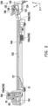
- FIG. 2 is a schematic three-dimensional cross-sectional view of a stand, a release component, and a part of the connector when the button of FIG. 1 is not yet pressed.
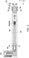
- FIG. 3 is a schematic bottom view of the stand, the release component, and the part of the connector of FIG. 2 .
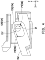
- FIG. 4 is a partial side view of the rotating button and the linking member of FIG. 2 .
- the linking member 150b is movably disposed beside the rotating button 124 and does not contact the rotating button 124 ( FIG. 4 ) under normal conditions.
- the linking member 150b includes a first section 152 and a second section 154 that are linked to each other.
- the first section 152 is disposed beside the rotating button 124.
- the second section 154 is away from the connector 120, and the first section 152 and the second section 154 extend in different directions.
- the first section 152 extends along the X-axis direction and the second section 154 extends along the Y-axis direction.
- the first section 152 and the second section 154 are integrally formed, but not limited thereto.
- the first section 152 may be screwed to the second section 154.
- the button 150a is disposed beside the second section 154 and is linked to the second section 154.
- a movement direction of the button 150a is different from a movement direction of the linking member 150b.
- the button 150a of this embodiment may move along the Z-axis direction and the linking member 150b may move along the X-axis direction.
- the first section 152 does not contact the rotating button 124 ( FIG. 4 ) under normal conditions but contacts and pulls the rotating button 124 when triggered by an external force.
- the rotating button 124 includes a rotating button body 125 and a protruding post 126 protruding from the rotating button body 125.
- the first section 152 of the linking member 150b extends next to the rotating button body 125 and does not contact the rotating button body 125 ( FIG. 3 ).
- the first section 152 includes a wall 156 ( FIG. 2 ), and the wall 156 is arranged to form an elongated hole 157.
- the protruding post 126 is located in the elongated hole 157.
- the wall 156 includes a first portion P1 away from the second section 154 and a second portion P2 close to the second section 154.
- a distance between the first portion P1 of the wall 156 and the protruding post 126 is less than a distance between the second portion P2 of the wall 156 and the protruding post 126.
- the protruding post 126 is eccentrically penetrated through the elongated hole 157.
- the elongated hole 157 is a closed hole located inside the first section 152, but not limited thereto.
- the first portion P1 and the second portion P2 of the wall 156 do not contact the protruding post 126 under normal conditions when the button 150a is not yet pressed.
- a distance D1 is provided between the first portion P1 of the wall 156 and the protruding post 126.
- the release component 150 further includes an elastic member 150c.
- the elastic member 150c is disposed between the stand 140 and the first section 152 of the linking member 150b. The elastic member 150c is not deformed when the button 150a is not yet pressed.
- the left side of FIG. 2 shows the button 150a and a part of the second section 154 of the linking member 150b.
- the button 150a includes a first pushing area B1 and the first pushing area B1 is a slope.
- the second section 154 includes a corresponding second pushing area B2 and the second pushing area B2 is also a slope, but not limited thereto.
- the inclined first push area B1 is suitable for changing the movement direction.
- FIG. 5 is a schematic three-dimensional cross-sectional view of a stand, a release component, and a portion of the connector when the button of FIG. 1 is pressed.
- FIG. 6 is a schematic bottom view of the stand, the release component, and the part of the connector of FIG. 5 .
- FIG. 7 is a partial side view of the rotating button and the linking member of FIG. 5 .
- the inclined first pushing area B1 pushes the second pushing area B2, so that the second pushing area B2 (the second section 154) is moved to the +X-axis direction. Since the first section 152 is linked with the second section 154, the first section 152 moves along the X-axis direction and pulls the rotating button 124 to rotate, and the connector 120 is opened.
- the first portion P1 of the wall 156 of the first section 152 moves a distance D1 ( FIG. 4 ) to contact and pull the protruding post 126.
- the protruding post 126 drives the rotating button body 125 to rotate counterclockwise relative to the base body 122 (i.e., toward the circuit board body 110 of FIG. 1 ).
- the rotating button body 125 is in an open position, and the connector 120 is in an open state.
- the second portion P2 of the wall 156 still does not contact the protruding post 126 ( FIG. 7 ).
- the stand 140 of this embodiment includes a first limiting portion C1.
- the linking member 150b includes a second limiting portion C2 corresponding to the first limiting portion C1.
- the first limiting portion C1 is, for example, a protrusion.
- the second limiting portion C2 is, for example, an opening extending along the X-axis direction.
- the first limiting portion C1 penetrates the second limiting portion C2.
- the circuit board module 100 of this embodiment further includes a spring 160.
- the spring 160 is disposed between the button 150a and the stand 140.
- the spring 160 deforms and accumulates elastic potential energy.
- the spring 160 is adapted to lift the button 150a back to the position shown in FIG. 2 (and FIG. 8 ).
- FIG. 8 is a schematic three-dimensional cross-sectional view of the stand, the release component, and the part of the connector when the external force of FIG. 5 is released.
- FIG. 9 is a partial side view of the rotating button and the linking member of FIG. 8 . Referring to FIG. 8 and FIG. 9 at the same time, when the external force on the button 150a of FIG. 5 is released, the button 150a may be reset back to the position shown in FIG. 8 by the elastic potential energy provided by the spring 160. At this time, the schematic bottom view of the release component 150 and the stand 140 is shown in FIG. 3 , which is not repeated herein.
- the first pushing area B1 of the button 150a moves away from the second pushing area B2 of the linking member 150b.
- the linking member 150b may be reset back to the position shown in FIG. 8 by the elastic potential energy provided by the elastic member 150c.
- the connector 120 since the second portion P2 does not contact the protruding post 126, even if the external force on the button 150a is released, the connector 120 is still in an open state for the user to insert and remove the graphic card. In other words, the user does not need to keep pressing the button 150a when inserting and removing the graphic card, which may improve the convenience of using the circuit board module 100.
- the graphic card drives and resets the rotating button 124.
- the rotating button 124 is rotated from the open position shown in FIG. 8 back to the closed position shown in FIG. 2 , at which time the connector 120 is in a closed state and may hold the graphic card firmly.
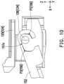
- FIG. 10 is a side view of a rotating button and a linking member according to another embodiment of the disclosure.
- the elongated hole 157a of this embodiment is similar to the above-mentioned embodiment, and the difference between the two is:
- the elongated hole 157a of this embodiment is an open hole recessed in an edge of the first section 152, and the open hole faces the circuit board body 110 shown in FIG. 1 (i.e., the C-shaped opening of the open hole is located on the lower side).
- the elongated hole 157a is substantially C-shaped.
- the elongated hole 157a of this embodiment are identical to those described in the above-mentioned embodiment. Hence, a detailed description thereof is omitted.
- the protruding post 126 may enter into the elongated hole 157a through the C-shaped opening of the elongated hole 157a, thereby improving the convenience of assembling between the linking member 150b and the connector 120.
- the protruding post 126 does not move out of the elongated hole 157a from the C-shaped opening.
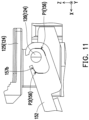
- FIG. 11 is a side view of a rotating button and a linking member according to another embodiment of the disclosure.
- the elongated hole 157b of this embodiment is similar to the above-mentioned embodiment, and the difference between the two is:
- the elongated hole 157b of this embodiment is an open hole, and open hole faces away from the circuit board body 110 shown in FIG. 1 (i.e., the C-shaped opening of the open hole is located on the upper side).
- the elongated hole 157b of this embodiment are identical to those described in the above-mentioned embodiment. Hence, a detailed description thereof is omitted. Users may dispose the elongated holes 157, 157a, 157b according to their needs.
- the circuit board module of the disclosure includes a circuit board body and a connector and a release component disposed on the circuit board body.
- the release component is linked with the connector, and the user may remotely open the connector through the release component.
- the linking member of the release component does not contact the protruding post of the rotating button of the connector under normal conditions.
- the button of the release component is triggered by an external force, the linking member needs to move a distance to contact the protruding post, so that the linking member may pull the protruding post and open the connector. Therefore, when the release component is accidentally shaken due to transportation or mis-touching, the displacement caused by the vibration is not enough to make the linking member contact the protruding post.
- the linking member is unable to pull the protruding post, so the connector is kept closed. This ensures that the connector is not opened due to accidental vibration or unintentional operation, which improves the stability of the circuit board module.
- the linking member does not contact the rotating button body of the rotating button, so that there is no friction between the linking member and the rotating button. Therefore, when the linking member moves relative to the rotating button, the movement of the linking member is not affected by the rotating button body, and the effect of labor-saving may be achieved.
Landscapes
- Engineering & Computer Science (AREA)
- Theoretical Computer Science (AREA)
- Microelectronics & Electronic Packaging (AREA)
- Computer Hardware Design (AREA)
- Power Engineering (AREA)
- Human Computer Interaction (AREA)
- Physics & Mathematics (AREA)
- General Engineering & Computer Science (AREA)
- General Physics & Mathematics (AREA)
- Computer Security & Cryptography (AREA)
- Coupling Device And Connection With Printed Circuit (AREA)
Abstract
Description
- The disclosure relates to a circuit board module and a release component, and in particular to a release component of a remote-control connector and a circuit board module including the release component.
- The rotating button of the PCI-E connector is located at the end of the connector. The expansion card inserted in the PCI-E connector is lifted by pressing the rotating button. In response to the increasing size of electronic elements that disable users from pressing the rotating button, the rotating buttons on existing PCI-E connectors may be opened via a remote-control component. For example, pressing the button of the remote-control component to move the rotating button, thereby lifting the expansion card in the PCI-E connector. However, the remote-control component is vulnerable to accidental vibration caused by transportation or mis-touching that may cause the rotating button to move, resulting in electronic elements being accidentally lifted inside the PCI-E connector and affecting the operation of the circuit board.
- The disclosure provides a release component and a circuit board module including the release component, which prevent a connector from being accidentally opened.
- The circuit board module of the disclosure includes a circuit board body, a connector, and a release component. The connector is disposed on the circuit board body and includes a base body and a rotating button rotatably disposed on the base body. The release component is disposed on the circuit board body and includes a linking member. The linking member is movably disposed beside the rotating button and does not contact the rotating button under normal conditions. When an external force triggers the release component, the linking member is driven to contact the rotating button, so that the rotating button rotates relative to the base body.
- In an embodiment of the disclosure, the linking member includes a first section and a second section that are linked to each other. The first section is disposed beside the rotating button. The first section does not contact the rotating button under normal conditions but contacts the rotating button when triggered by an external force. The second section is away from the connector and the first section and the second section extend in different directions.
- In an embodiment of the disclosure, the release component further includes a button disposed on the circuit board body and away from the connector. The button is linked to the second section and a movement direction of the button is different from a movement direction of the linking member.
- In an embodiment of the disclosure, the rotating button includes a protruding post. The first section includes an elongated hole. The protruding post is located in the elongated hole.
- In an embodiment of the disclosure, the elongated hole is a closed hole located inside the first section.
- In an embodiment of the disclosure, the elongated hole is an open hole recessed in an edge of the first section, and the open hole faces the circuit board body.
- In an embodiment of the disclosure, the elongated hole is an open hole recessed in an edge of the first section, and the open hole faces away from the circuit board body.
- In an embodiment of the disclosure, the first section includes a wall arranged to form an elongated hole. The wall includes a first portion away from the second section and a second portion close to the second section. A distance between the first portion of the wall and the protruding post is less than a distance between the second portion of the wall and the protruding post.
- In an embodiment of the disclosure, the first portion of the wall does not contact the protruding post under normal conditions but contacts and pulls the protruding post when triggered by the external force. The second portion of the wall does not contact the protruding post.
- In an embodiment of the disclosure, the rotating button includes a rotating button body and a protruding post protruding from the rotating button body. The first section extends next to the rotating button body and does not contact the rotating button body.
- In an embodiment of the disclosure, the circuit board module further includes a stand disposed on the circuit board body. The linking member is movably disposed between the stand and the circuit board body. The release component further includes an elastic member disposed between the stand and the linking member and configured to reset the linking member when the external force is released.
- The release component of the disclosure is adapted to be disposed beside a connector, so that the rotating button of the connector is rotated relative to a base body. The release component includes a linking member, a button, and an elastic member. The linking member is movably disposed beside the rotating button and does not contact the rotating button under normal conditions. The button is linked to the linking member and away from the connector. A movement direction of the button is different from a movement direction of the linking member. The elastic member is abutting against the linking member. The linking member is driven to contact the rotating button when an external force triggers the button, so that the rotating button rotates relative to the base body and the elastic member is compressed. The elastic member recovers to reset the linking member when the external force is released.
- In an embodiment of the disclosure, the linking member includes a first section and a second section that are linked to each other. The first section is disposed beside the rotating button. The first section does not contact the rotating button under normal conditions but contacts the rotating button when triggered by an external force. The second section is away from the connector and the first section and the second section extend in different directions.
- In an embodiment of the disclosure, the rotating button includes a protruding post. The first section includes an elongated hole. The protruding post is located in the elongated hole.
- In an embodiment of the disclosure, the elongated hole is a closed hole located inside the first section.
- In an embodiment of the disclosure, the elongated hole is an open hole recessed in an edge of the first section.
- In an embodiment of the disclosure, the first section includes a wall arranged to form an elongated hole. The wall includes a first portion away from the second section and a second portion close to the second section. A distance between the first portion of the wall and the protruding post is less than a distance between the second portion of the wall and the protruding post.
- In an embodiment of the disclosure, the first portion of the wall does not contact the protruding post under normal conditions but contacts and pulls the protruding post when triggered by the external force. The second portion of the wall does not contact the protruding post.
- In an embodiment of the disclosure, the rotating button includes a rotating button body and a protruding post protruding from the rotating button body. The first section extends next to the rotating button body and does not contact the rotating button body.
- Based on the above, the circuit board module of the disclosure includes a circuit board body and a release component and a connector disposed on the circuit board body. The release component is linked with the connector, and the user may remotely open the connector through the release component. The linking member of the release component does not contact the rotating button of the connector under normal conditions. When the user triggers the release component, the linking member needs to move a distance to contact the rotating button, so that the linking member may pull the rotating button and open the connector. When the release component is accidentally shaken due to transportation or mis-touching, the displacement caused by the vibration is not enough to make the linking member contact the rotating button. The linking member is unable to pull the rotating button, so the connector is kept closed. This ensures that the connector is not opened due to accidental vibration or unintentional operation, which improves the stability of the circuit board module.
-
FIG. 1 is a schematic view of a circuit board module according to an embodiment of the disclosure. Cartesian coordinates XYZ are also provided here to facilitate component description. Referring toFIG. 1 , thecircuit board module 100 of the disclosure includes acircuit board body 110, aconnector 120, arelease component 150, and astand 140. Theconnector 120, therelease component 150, and thestand 140 are disposed on thecircuit board body 110. Theconnector 120 includes abase body 122 and arotating button 124 rotatably disposed on thebase body 122. - The
connector 120 is, for example, a PCI-E connector, but not limited thereto. Theconnector 120 is suitable for inserting a graphic card (not shown). Since the current graphic card is usually equipped with large cooling fins and fans, therotating button 124 is easily covered, resulting in difficulty for the user in removing the graphic card by pulling therotating button 124 directly. - For convenience in pulling the
rotating button 124 to remove the graphic card, therelease component 150 includes a linkingmember 150b and abutton 150a. Thebutton 150a is linked with therotating button 124 through the linkingmember 150b. When an external force triggers thebutton 150a of therelease component 150, the linkingmember 150b is driven to contact and pull therotating button 124, so that therotating button 124 rotates relative to thebase body 122 to open theconnector 120. Thebutton 150a is disposed on thecircuit board body 110 and away from theconnector 120. Since anedge 112 of thecircuit board body 110 is less disposed with large elements, disposing thebutton 150a on theedge 112 of thecircuit board body 110 may prevent thebutton 150a from being covered by other elements. - In addition, the linking
member 150b is movably disposed between thestand 140 and thecircuit board body 110. Thestand 140 is disposed on the release component 150 (FIG. 2 ), thereby limiting the movement direction of therelease component 150. Thestand 140 and therelease component 150 are substantially L-shaped, and therotating button 124 and thebutton 150a are staggered in the X-axis direction, but not limited thereto. The user may change the disposition of thestand 140 and therelease component 150 according to the layout of the elements on thecircuit board body 110, so that thebutton 150a is located at a position that is convenient for pressing. -
FIG. 2 is a schematic three-dimensional cross-sectional view of a stand, a release component, and a part of the connector when the button ofFIG. 1 is not yet pressed.FIG. 3 is a schematic bottom view of the stand, the release component, and the part of the connector ofFIG. 2 .FIG. 4 is a partial side view of the rotating button and the linking member ofFIG. 2 . - Referring to
FIG. 2 andFIG. 4 at the same time, the linkingmember 150b is movably disposed beside therotating button 124 and does not contact the rotating button 124 (FIG. 4 ) under normal conditions. The linkingmember 150b includes afirst section 152 and asecond section 154 that are linked to each other. Thefirst section 152 is disposed beside therotating button 124. Thesecond section 154 is away from theconnector 120, and thefirst section 152 and thesecond section 154 extend in different directions. - The
first section 152 extends along the X-axis direction and thesecond section 154 extends along the Y-axis direction. Thefirst section 152 and thesecond section 154 are integrally formed, but not limited thereto. For example, in other embodiments, thefirst section 152 may be screwed to thesecond section 154. - The
button 150a is disposed beside thesecond section 154 and is linked to thesecond section 154. A movement direction of thebutton 150a is different from a movement direction of the linkingmember 150b. For example, thebutton 150a of this embodiment may move along the Z-axis direction and the linkingmember 150b may move along the X-axis direction. Thefirst section 152 does not contact the rotating button 124 (FIG. 4 ) under normal conditions but contacts and pulls therotating button 124 when triggered by an external force. - Specifically, as shown in
FIG. 3 andFIG. 4 , therotating button 124 includes arotating button body 125 and aprotruding post 126 protruding from therotating button body 125. Thefirst section 152 of the linkingmember 150b extends next to therotating button body 125 and does not contact the rotating button body 125 (FIG. 3 ). Thefirst section 152 includes a wall 156 (FIG. 2 ), and thewall 156 is arranged to form anelongated hole 157. The protrudingpost 126 is located in theelongated hole 157. - Referring to
FIG. 4 , thewall 156 includes a first portion P1 away from thesecond section 154 and a second portion P2 close to thesecond section 154. A distance between the first portion P1 of thewall 156 and the protrudingpost 126 is less than a distance between the second portion P2 of thewall 156 and the protrudingpost 126. The protrudingpost 126 is eccentrically penetrated through theelongated hole 157. Theelongated hole 157 is a closed hole located inside thefirst section 152, but not limited thereto. - The first portion P1 and the second portion P2 of the
wall 156 do not contact the protrudingpost 126 under normal conditions when thebutton 150a is not yet pressed. Referring toFIG. 4 , a distance D1 is provided between the first portion P1 of thewall 156 and the protrudingpost 126. When therelease component 150 is accidentally shaken due to transportation or mis-touching, the small displacement caused by the vibration is not enough to make thewall 156 contact the protruding post 126 (i.e., the displacement of thewall 156 is less than the distance D1). The linkingmember 150b is unable to pull therotating button 124 so that theconnector 120 is kept closed. In other words, this ensures that theconnector 120 is not opened due to accidental vibration or unintentional operation, which improves the stability of thecircuit board module 100. - In addition, as shown in
FIG. 2 andFIG. 3 , therelease component 150 further includes anelastic member 150c. Theelastic member 150c is disposed between thestand 140 and thefirst section 152 of the linkingmember 150b. Theelastic member 150c is not deformed when thebutton 150a is not yet pressed. - The left side of
FIG. 2 shows thebutton 150a and a part of thesecond section 154 of the linkingmember 150b. Thebutton 150a includes a first pushing area B1 and the first pushing area B1 is a slope. Thesecond section 154 includes a corresponding second pushing area B2 and the second pushing area B2 is also a slope, but not limited thereto. The inclined first push area B1 is suitable for changing the movement direction. -
FIG. 5 is a schematic three-dimensional cross-sectional view of a stand, a release component, and a portion of the connector when the button ofFIG. 1 is pressed.FIG. 6 is a schematic bottom view of the stand, the release component, and the part of the connector ofFIG. 5 .FIG. 7 is a partial side view of the rotating button and the linking member ofFIG. 5 . - Referring to
FIG. 5 to FIG. 7 at the same time, when thebutton 150a is pressed down along the -Z axis direction, the inclined first pushing area B1 pushes the second pushing area B2, so that the second pushing area B2 (the second section 154) is moved to the +X-axis direction. Since thefirst section 152 is linked with thesecond section 154, thefirst section 152 moves along the X-axis direction and pulls therotating button 124 to rotate, and theconnector 120 is opened. - Specifically, as shown in
FIG. 5 andFIG. 7 , the first portion P1 of thewall 156 of thefirst section 152 moves a distance D1 (FIG. 4 ) to contact and pull the protrudingpost 126. The protrudingpost 126 drives therotating button body 125 to rotate counterclockwise relative to the base body 122 (i.e., toward thecircuit board body 110 ofFIG. 1 ). At this time, therotating button body 125 is in an open position, and theconnector 120 is in an open state. The second portion P2 of thewall 156 still does not contact the protruding post 126 (FIG. 7 ). - As shown in
FIG. 5 , when thebutton 150a is pressed, the movement of thefirst section 152 of the linkingmember 150b drives theelastic member 150c to deform and accumulate elastic potential energy. For preventing the linkingmember 150b from rotating when moving along the +X-axis direction, thestand 140 of this embodiment includes a first limiting portion C1. The linkingmember 150b includes a second limiting portion C2 corresponding to the first limiting portion C1. - The first limiting portion C1 is, for example, a protrusion. The second limiting portion C2 is, for example, an opening extending along the X-axis direction. The first limiting portion C1 penetrates the second limiting portion C2. When the linking
member 150b moves along the X-axis direction, the first limiting portion C1 and the second limiting portion C2 cooperate with each other so that the linkingmember 150b may only move along the X-axis direction without rotating. In this way, the linkingmember 150b may drive therotating button 124 more stably. - In addition, as shown in
FIG. 3 andFIG. 6 , no matter whether thebutton 150a is pressed or not, thefirst section 152 of the linkingmember 150b does not contact with therotating button body 125. Therefore, there is no friction between the linkingmember 150b and therotating button body 125. When thebutton 150a is pressed, the movement of thefirst section 152 is not affected by therotating button body 125, and the effect of labor-saving may be achieved. - The
circuit board module 100 of this embodiment further includes aspring 160. As shown on the left side ofFIG. 5 , thespring 160 is disposed between thebutton 150a and thestand 140. When thebutton 150a is pressed (FIG. 5 ), thespring 160 deforms and accumulates elastic potential energy. When the external force is released, thespring 160 is adapted to lift thebutton 150a back to the position shown inFIG. 2 (andFIG. 8 ). -
FIG. 8 is a schematic three-dimensional cross-sectional view of the stand, the release component, and the part of the connector when the external force ofFIG. 5 is released.FIG. 9 is a partial side view of the rotating button and the linking member ofFIG. 8 . Referring toFIG. 8 andFIG. 9 at the same time, when the external force on thebutton 150a ofFIG. 5 is released, thebutton 150a may be reset back to the position shown inFIG. 8 by the elastic potential energy provided by thespring 160. At this time, the schematic bottom view of therelease component 150 and thestand 140 is shown inFIG. 3 , which is not repeated herein. - The first pushing area B1 of the
button 150a moves away from the second pushing area B2 of the linkingmember 150b. The linkingmember 150b may be reset back to the position shown inFIG. 8 by the elastic potential energy provided by theelastic member 150c. - As shown in
FIG. 9 , when the linkingmember 150b is reset, the first portion P1 of thewall 156 moves away from the protrudingpost 126, the second portion P2 moves close to the protrudingpost 126 but does not contact the protrudingpost 126, and the rotating button 124 (FIG. 8 ) is still in the open position. In light of the above, no matter how the linkingmember 150b moves, the second portion P2 of thewall 156 does not contact the protrudingpost 126. - In this embodiment, since the second portion P2 does not contact the protruding
post 126, even if the external force on thebutton 150a is released, theconnector 120 is still in an open state for the user to insert and remove the graphic card. In other words, the user does not need to keep pressing thebutton 150a when inserting and removing the graphic card, which may improve the convenience of using thecircuit board module 100. - In addition, when the user inserts the graphic card, the graphic card drives and resets the
rotating button 124. Therotating button 124 is rotated from the open position shown inFIG. 8 back to the closed position shown inFIG. 2 , at which time theconnector 120 is in a closed state and may hold the graphic card firmly. -
FIG. 10 is a side view of a rotating button and a linking member according to another embodiment of the disclosure. Referring toFIG. 4 andFIG. 10 at the same time, theelongated hole 157a of this embodiment is similar to the above-mentioned embodiment, and the difference between the two is: Theelongated hole 157a of this embodiment is an open hole recessed in an edge of thefirst section 152, and the open hole faces thecircuit board body 110 shown inFIG. 1 (i.e., the C-shaped opening of the open hole is located on the lower side). Theelongated hole 157a is substantially C-shaped. Theelongated hole 157a of this embodiment are identical to those described in the above-mentioned embodiment. Hence, a detailed description thereof is omitted. - It is worth mentioning that the protruding
post 126 may enter into theelongated hole 157a through the C-shaped opening of theelongated hole 157a, thereby improving the convenience of assembling between the linkingmember 150b and theconnector 120. When thefirst section 152 of the linkingmember 150b moves between the positions shown inFIG. 4 andFIG. 7 , the protrudingpost 126 does not move out of theelongated hole 157a from the C-shaped opening. -
FIG. 11 is a side view of a rotating button and a linking member according to another embodiment of the disclosure. Referring toFIG. 10 andFIG. 11 at the same time, theelongated hole 157b of this embodiment is similar to the above-mentioned embodiment, and the difference between the two is: Theelongated hole 157b of this embodiment is an open hole, and open hole faces away from thecircuit board body 110 shown inFIG. 1 (i.e., the C-shaped opening of the open hole is located on the upper side). Theelongated hole 157b of this embodiment are identical to those described in the above-mentioned embodiment. Hence, a detailed description thereof is omitted. Users may dispose theelongated holes - To sum up, the circuit board module of the disclosure includes a circuit board body and a connector and a release component disposed on the circuit board body. The release component is linked with the connector, and the user may remotely open the connector through the release component. The linking member of the release component does not contact the protruding post of the rotating button of the connector under normal conditions. When the button of the release component is triggered by an external force, the linking member needs to move a distance to contact the protruding post, so that the linking member may pull the protruding post and open the connector. Therefore, when the release component is accidentally shaken due to transportation or mis-touching, the displacement caused by the vibration is not enough to make the linking member contact the protruding post. The linking member is unable to pull the protruding post, so the connector is kept closed. This ensures that the connector is not opened due to accidental vibration or unintentional operation, which improves the stability of the circuit board module.
- In addition, the linking member does not contact the rotating button body of the rotating button, so that there is no friction between the linking member and the rotating button. Therefore, when the linking member moves relative to the rotating button, the movement of the linking member is not affected by the rotating button body, and the effect of labor-saving may be achieved.
Claims (19)
- A circuit board module (100), comprising:a circuit board body (110);a connector (120), disposed on the circuit board body (110) and comprising a base body and a rotating button (124) rotatably disposed on the base body (122); anda release component (150), disposed on the circuit board body (110) and comprising a linking member (150b), wherein the linking member (150b) is movably disposed beside the rotating button (124) and does not contact the rotating button (124) under normal conditions,wherein the linking member (150b) is driven to contact the rotating button (124) when an external force triggers the release component (150), so that the rotating button (124) rotates relative to the base body (122).
- The circuit board module (100) according to claim 1, wherein the linking member (150b) comprises a first section (152) and a second section (154) that are linked to each other, the first section (152) is disposed beside the rotating button (124), the first section (152) does not contact the rotating button (124) under normal conditions but contacts the rotating button (124) when triggered by the external force, the second section (154) is away from the connector (120), and the first section (152) and the second section (154) extend in different directions.
- The circuit board module (100) according to claim 2, wherein the release component (150) further comprises a button (150a) disposed on the circuit board body (110) and away from the connector (120), the button (150a) is linked to the second section (154), and a movement direction of the button (150a) is different from a movement direction of the linking member (150b).
- The circuit board module (100) according to claim 2, wherein the rotating button (124) comprises a protruding post (126), the first section (152) comprises an elongated hole (157, 157a, 157b), and the protruding post (126) is located in the elongated hole (157, 157a, 157b).
- The circuit board module (100) according to claim 4, wherein the elongated hole (157, 157a, 157b) is a closed hole located inside the first section (152).
- The circuit board module (100) according to claim 4, wherein the elongated hole (157, 157a, 157b) is an open hole recessed in an edge (112) of the first section (152), and the open hole faces the circuit board body (110).
- The circuit board module (100) according to claim 4, wherein the elongated hole (157, 157a, 157b) is an open hole recessed in an edge (112) of the first section (152), and the open hole faces away from the circuit board body (110).
- The circuit board module (100) according to claim 4, wherein the first section (152) comprises a wall (156) arranged to form the elongated hole (157, 157a, 157b), the wall (156) comprises a first portion (PI) away from the second section (154) and a second portion (P2) close to the second section (154), a distance (D1) between the first portion (PI) of the wall (156) and the protruding post (126) is less than a distance (D1) between the second portion (P2) of the wall (156) and the protruding post (126).
- The circuit board module (100) according to claim 8, wherein the first portion (PI) of the wall (156) does not contact the protruding post (126) under normal conditions but contacts and pulls the protruding post (126) when triggered by the external force, and the second portion (P2) of the wall (156) does not contact the protruding post (126).
- The circuit board module (100) according to claim 2, wherein the rotating button (124) comprises a rotating button body (125) and a protruding post (126) protruding from the rotating button body (125), and the first section (152) extends next to the rotating button body (125) and does not contact the rotating button body (125).
- The circuit board module (100) according to claim 1, further comprising a stand (140) disposed on the circuit board body (110), wherein the linking member (150b) is movably disposed between the stand (140) and the circuit board body (110), and the release component (150) further comprises an elastic member (150c) disposed between the stand (140) and the linking member (150b) and configured to reset the linking member (150b) when the external force is released.
- A release component (150), adapted to be disposed beside a connector (120), so that a rotating button (124) of the connector (120) is rotated relative to a base body (122), the release component (150) comprising:a linking member (150b), movably disposed beside the rotating button (124) and not contacting the rotating button (124) under normal conditions;a button (150a), linked to the linking member (150b) and away from the connector (120), wherein a movement direction of the button (150a) is different from a movement direction of the linking member (150b); andan elastic member (150c), abutting against the linking member (150b),wherein the linking member (150b) is driven to contact the rotating button (124) when an external force triggers the button (150a), so that the rotating button (124) rotates relative to the base body (122) and the elastic member (150c) is compressed,wherein the elastic member (150c) recovers to reset the linking member (150b) when the external force is released.
- The release component (150) according to claim 12, wherein the linking member (150b) comprises a first section (152) and a second section (154) that are linked to each other, the first section (152) is disposed beside the rotating button (124), the first section (152) does not contact the rotating button (124) under normal conditions but contacts the rotating button (124) when triggered by the external force, the second section (154) is away from the connector (120), and the first section (152) and the second section (154) extend in different directions.
- The release component (150) according to claim 13, wherein the rotating button (124) comprises a protruding post (126), the first section (152) comprises an elongated hole (157, 157a, 157b), and the protruding post (126) is located in the elongated hole (157, 157a, 157b).
- The release component (150) according to claim 14, wherein the elongated hole (157, 157a, 157b) is a closed hole located inside the first section (152).
- The release component (150) according to claim 14, wherein the elongated hole (157, 157a, 157b) is an open hole recessed in an edge (112) of the first section (152).
- The release component (150) according to claim 14, wherein the first section (152) comprises a wall (156) arranged to form the elongated hole (157, 157a, 157b), the wall (156) comprises a first portion (PI) away from the second section (154) and a second portion (P2) close to the second section (154), a distance (D1) between the first portion (PI) of the wall (156) and the protruding post (126) is less than a distance (D1) between the second portion (P2) of the wall (156) and the protruding post (126).
- The release component (150) according to claim 17, wherein the first portion (PI) of the wall (156) does not contact the protruding post (126) under normal conditions but contacts and pulls the protruding post (126) when triggered by the external force, and the second portion (P2) of the wall (156) does not contact the protruding post (126).
- The release component (150) according to claim 13, wherein the rotating button (124) comprises a rotating button body (125) and a protruding post (126) protruding from the rotating button body (125), and the first section (152) extends next to the rotating button body (125) and does not contact the rotating button body (125).
Applications Claiming Priority (2)
| Application Number | Priority Date | Filing Date | Title |
|---|---|---|---|
| TW110145767A TWI805117B (en) | 2021-12-08 | 2021-12-08 | Circuit board module |
| TW111133307A TWI805475B (en) | 2021-12-08 | 2022-09-02 | Circuit board module and release component |
Publications (2)
| Publication Number | Publication Date |
|---|---|
| EP4198684A1 true EP4198684A1 (en) | 2023-06-21 |
| EP4198684B1 EP4198684B1 (en) | 2025-07-16 |
Family
ID=84053059
Family Applications (1)
| Application Number | Title | Priority Date | Filing Date |
|---|---|---|---|
| EP22206903.1A Active EP4198684B1 (en) | 2021-12-08 | 2022-11-11 | Circuit board module and release component |
Country Status (2)
| Country | Link |
|---|---|
| US (1) | US12374829B2 (en) |
| EP (1) | EP4198684B1 (en) |
Families Citing this family (4)
| Publication number | Priority date | Publication date | Assignee | Title |
|---|---|---|---|---|
| CN216488833U (en) * | 2021-10-27 | 2022-05-10 | 安费诺商用电子产品(成都)有限公司 | electrical connector |
| TWM654727U (en) | 2022-04-18 | 2024-05-01 | 大陸商安費諾商用電子產品(成都)有限公司 | Electrical connectors |
| TWI796232B (en) * | 2022-06-01 | 2023-03-11 | 華碩電腦股份有限公司 | Circuit board |
| TWI866477B (en) * | 2023-02-21 | 2024-12-11 | 雙鴻科技股份有限公司 | Interface card quick release device |
Citations (5)
| Publication number | Priority date | Publication date | Assignee | Title |
|---|---|---|---|---|
| US6406309B1 (en) * | 2000-09-29 | 2002-06-18 | International Business Machines Corporation | Enhanced arrangement for disengaging and separating two mated components |
| US20140254086A1 (en) * | 2012-06-21 | 2014-09-11 | Huawei Technologies Co., Ltd. | Pluggable Apparatus of Circuit Board, and Server |
| EP2793245A1 (en) * | 2013-04-18 | 2014-10-22 | Valeo Japan Co., Ltd. | Push switch |
| US20160109910A1 (en) * | 2014-10-15 | 2016-04-21 | Hong Fu Jin Precision Industry (Wuhan) Co., Ltd. | Securing structure for expansion card |
| US20180090862A1 (en) * | 2016-09-29 | 2018-03-29 | Intel Corporation | Circuit board with a connector having a latch that includes a latch frame, a latch slide, an ejector and a connector arm |
Family Cites Families (33)
| Publication number | Priority date | Publication date | Assignee | Title |
|---|---|---|---|---|
| US4159861A (en) | 1977-12-30 | 1979-07-03 | International Telephone And Telegraph Corporation | Zero insertion force connector |
| TW390521U (en) * | 1997-06-05 | 2000-05-11 | Hon Hai Prec Ind Co Ltd | Electric connector |
| US5815377A (en) | 1997-12-08 | 1998-09-29 | International Business Machines Corporation | Apparatus for auto docking PCI cards |
| CN102478908A (en) | 2010-11-23 | 2012-05-30 | 鸿富锦精密工业(深圳)有限公司 | Memory stick holding device |
| GB2396488B (en) * | 2002-12-17 | 2004-12-01 | Giga Byte Tech Co Ltd | Card connector for securing a daughter board to a mother board |
| EP1450443A1 (en) * | 2003-02-21 | 2004-08-25 | Hewlett-Packard Development Company, L.P. | An I/O expansion system and a connector therefor |
| CN2687890Y (en) * | 2003-12-09 | 2005-03-23 | 富士康(昆山)电脑接插件有限公司 | Card fastening device |
| US7121836B2 (en) * | 2005-02-01 | 2006-10-17 | Giga-Byte Technology Co., Ltd. | Integrated socket |
| US7160126B1 (en) * | 2005-09-06 | 2007-01-09 | Giga-Byte Technology Co., Ltd. | Printed circuit board connector with locking device |
| CN101290536B (en) | 2007-04-20 | 2011-09-28 | 鸿富锦精密工业(深圳)有限公司 | Expansion card fixer |
| SG162635A1 (en) * | 2008-12-23 | 2010-07-29 | Molex Inc | Card edge connector |
| JP4915879B2 (en) * | 2009-08-10 | 2012-04-11 | 株式会社アイペックス | Connector device |
| US7862368B1 (en) * | 2009-08-12 | 2011-01-04 | Giga-Byte Technology Co., Ltd. | Socket assembly |
| US8657612B2 (en) * | 2010-10-18 | 2014-02-25 | Giga-Byte Technology Co., Ltd. | Socket and motherboard with the same |
| US8277235B2 (en) * | 2010-10-18 | 2012-10-02 | Giga-Byte Technology Co., Ltd. | Socket and motherboard with the same |
| CN102761028A (en) * | 2011-04-28 | 2012-10-31 | 鸿富锦精密工业(深圳)有限公司 | Board card fixing device |
| TWI535121B (en) * | 2012-12-19 | 2016-05-21 | 技嘉科技股份有限公司 | Electrical connector |
| US9395772B2 (en) * | 2013-06-07 | 2016-07-19 | Apple Inc. | Computer internal architecture |
| US9063705B2 (en) * | 2013-11-11 | 2015-06-23 | Lenovo Enterprise Solutions (Singapore) Pte. Ltd. | Latch mechanism for securing an electronic module |
| JP6738800B2 (en) * | 2014-07-29 | 2020-08-12 | スリーエム イノベイティブ プロパティズ カンパニー | Multi-row connector with zero insertion force |
| CN204668610U (en) | 2015-04-02 | 2015-09-23 | 上海莫仕连接器有限公司 | Electric connector |
| TWI539691B (en) * | 2015-11-27 | 2016-06-21 | 技嘉科技股份有限公司 | Connector cover and connector module |
| JP6583961B2 (en) | 2015-12-18 | 2019-10-02 | ヒロセ電機株式会社 | connector |
| CN107678504B (en) | 2016-08-02 | 2019-11-01 | 纬创资通(中山)有限公司 | expansion card assembly |
| TWI619421B (en) * | 2016-10-06 | 2018-03-21 | 技嘉科技股份有限公司 | Interface card fixing device and main board module |
| EP3513637B1 (en) * | 2016-12-21 | 2021-05-19 | Hewlett-Packard Development Company, L.P. | Retainers with movable hooks |
| CN111752344B (en) * | 2019-03-27 | 2022-04-12 | 纬联电子科技(中山)有限公司 | Auxiliary unlocking structure and electronic device |
| CN210897707U (en) * | 2019-12-11 | 2020-06-30 | 富士康(昆山)电脑接插件有限公司 | Card edge connector |
| TWM595343U (en) | 2019-12-17 | 2020-05-11 | 台灣莫仕股份有限公司 | Connector |
| US11340665B2 (en) * | 2020-09-03 | 2022-05-24 | Quanta Computer Inc. | Tiered locking mechanism for securing component cards to different height connectors for a main board |
| TWM611095U (en) | 2020-09-07 | 2021-05-01 | 廣達電腦股份有限公司 | Facilitated expansion card removal system and expansion card release apparatus |
| TWM610315U (en) | 2020-11-16 | 2021-04-11 | 廣達電腦股份有限公司 | A riser bracket assembly and a computing system with the riser bracket assembly |
| TWI769886B (en) * | 2021-07-07 | 2022-07-01 | 華碩電腦股份有限公司 | Circuit board |
-
2022
- 2022-10-14 US US17/965,785 patent/US12374829B2/en active Active
- 2022-11-11 EP EP22206903.1A patent/EP4198684B1/en active Active
Patent Citations (5)
| Publication number | Priority date | Publication date | Assignee | Title |
|---|---|---|---|---|
| US6406309B1 (en) * | 2000-09-29 | 2002-06-18 | International Business Machines Corporation | Enhanced arrangement for disengaging and separating two mated components |
| US20140254086A1 (en) * | 2012-06-21 | 2014-09-11 | Huawei Technologies Co., Ltd. | Pluggable Apparatus of Circuit Board, and Server |
| EP2793245A1 (en) * | 2013-04-18 | 2014-10-22 | Valeo Japan Co., Ltd. | Push switch |
| US20160109910A1 (en) * | 2014-10-15 | 2016-04-21 | Hong Fu Jin Precision Industry (Wuhan) Co., Ltd. | Securing structure for expansion card |
| US20180090862A1 (en) * | 2016-09-29 | 2018-03-29 | Intel Corporation | Circuit board with a connector having a latch that includes a latch frame, a latch slide, an ejector and a connector arm |
Also Published As
| Publication number | Publication date |
|---|---|
| US20230178935A1 (en) | 2023-06-08 |
| US12374829B2 (en) | 2025-07-29 |
| EP4198684B1 (en) | 2025-07-16 |
Similar Documents
| Publication | Publication Date | Title |
|---|---|---|
| US12374829B2 (en) | Circuit board module and release component | |
| US7286344B2 (en) | Port replicator | |
| CN116249265B (en) | Circuit board module and release assembly | |
| CN101657777B (en) | Electronic device locking system | |
| US6830385B2 (en) | Package having lock mechanism | |
| US5395268A (en) | Modular jack | |
| EP4195000B1 (en) | Remote releasing module and circuit board device | |
| JP2012128773A (en) | Function expansion unit and electronic device system | |
| US9426917B2 (en) | Socket assembly with pick up cap | |
| JP2018181499A (en) | Connector and connector assembly | |
| US6392874B1 (en) | Computer casing with internal fastener | |
| US20080188097A1 (en) | Electrical connector with guiding poriton | |
| CN118016459A (en) | Micro-gap switch convenient to change | |
| US8259438B2 (en) | Button locking mechanism for preventing a button from being pressed down and electronic device thereof | |
| CN103779704B (en) | Connector structure and electronic device | |
| CN115954720B (en) | Easy-to-operate plug-in connector | |
| JP2003077585A (en) | Cable connector | |
| CN102573343A (en) | Electronic device and sliding key of electronic device | |
| TWI805475B (en) | Circuit board module and release component | |
| US6439913B1 (en) | Simplified ZIF socket assembly | |
| JP2009176607A (en) | Parts support device | |
| CN111726432A (en) | Fixing device, fixing device assembly and electronic equipment | |
| US20070054529A1 (en) | Connector with improved operating portion | |
| KR20060050033A (en) | Latch device that does not require movable operation member operated from the outside | |
| JP2911366B2 (en) | Function expansion box |
Legal Events
| Date | Code | Title | Description |
|---|---|---|---|
| PUAI | Public reference made under article 153(3) epc to a published international application that has entered the european phase |
Free format text: ORIGINAL CODE: 0009012 |
|
| STAA | Information on the status of an ep patent application or granted ep patent |
Free format text: STATUS: THE APPLICATION HAS BEEN PUBLISHED |
|
| AK | Designated contracting states |
Kind code of ref document: A1 Designated state(s): AL AT BE BG CH CY CZ DE DK EE ES FI FR GB GR HR HU IE IS IT LI LT LU LV MC ME MK MT NL NO PL PT RO RS SE SI SK SM TR |
|
| STAA | Information on the status of an ep patent application or granted ep patent |
Free format text: STATUS: REQUEST FOR EXAMINATION WAS MADE |
|
| 17P | Request for examination filed |
Effective date: 20231017 |
|
| RBV | Designated contracting states (corrected) |
Designated state(s): AL AT BE BG CH CY CZ DE DK EE ES FI FR GB GR HR HU IE IS IT LI LT LU LV MC ME MK MT NL NO PL PT RO RS SE SI SK SM TR |
|
| GRAP | Despatch of communication of intention to grant a patent |
Free format text: ORIGINAL CODE: EPIDOSNIGR1 |
|
| STAA | Information on the status of an ep patent application or granted ep patent |
Free format text: STATUS: GRANT OF PATENT IS INTENDED |
|
| RIC1 | Information provided on ipc code assigned before grant |
Ipc: H01R 13/633 20060101ALN20250220BHEP Ipc: H01R 12/70 20110101ALN20250220BHEP Ipc: H05K 7/14 20060101ALI20250220BHEP Ipc: H01R 13/639 20060101ALI20250220BHEP Ipc: H01R 13/627 20060101ALI20250220BHEP Ipc: H01R 12/72 20110101ALI20250220BHEP Ipc: H01R 12/71 20110101ALI20250220BHEP Ipc: G06F 1/18 20060101AFI20250220BHEP |
|
| INTG | Intention to grant announced |
Effective date: 20250306 |
|
| GRAS | Grant fee paid |
Free format text: ORIGINAL CODE: EPIDOSNIGR3 |
|
| GRAA | (expected) grant |
Free format text: ORIGINAL CODE: 0009210 |
|
| STAA | Information on the status of an ep patent application or granted ep patent |
Free format text: STATUS: THE PATENT HAS BEEN GRANTED |
|
| AK | Designated contracting states |
Kind code of ref document: B1 Designated state(s): AL AT BE BG CH CY CZ DE DK EE ES FI FR GB GR HR HU IE IS IT LI LT LU LV MC ME MK MT NL NO PL PT RO RS SE SI SK SM TR |
|
| REG | Reference to a national code |
Ref country code: GB Ref legal event code: FG4D |
|
| REG | Reference to a national code |
Ref country code: CH Ref legal event code: EP |
|
| REG | Reference to a national code |
Ref country code: DE Ref legal event code: R096 Ref document number: 602022017605 Country of ref document: DE |
|
| REG | Reference to a national code |
Ref country code: IE Ref legal event code: FG4D |
|
| PGFP | Annual fee paid to national office [announced via postgrant information from national office to epo] |
Ref country code: FR Payment date: 20250908 Year of fee payment: 4 |
|
| REG | Reference to a national code |
Ref country code: NL Ref legal event code: MP Effective date: 20250716 |
|
| PG25 | Lapsed in a contracting state [announced via postgrant information from national office to epo] |
Ref country code: PT Free format text: LAPSE BECAUSE OF FAILURE TO SUBMIT A TRANSLATION OF THE DESCRIPTION OR TO PAY THE FEE WITHIN THE PRESCRIBED TIME-LIMIT Effective date: 20251117 |
|
| PG25 | Lapsed in a contracting state [announced via postgrant information from national office to epo] |
Ref country code: NL Free format text: LAPSE BECAUSE OF FAILURE TO SUBMIT A TRANSLATION OF THE DESCRIPTION OR TO PAY THE FEE WITHIN THE PRESCRIBED TIME-LIMIT Effective date: 20250716 |
|
| REG | Reference to a national code |
Ref country code: AT Ref legal event code: MK05 Ref document number: 1814615 Country of ref document: AT Kind code of ref document: T Effective date: 20250716 |
|
| PG25 | Lapsed in a contracting state [announced via postgrant information from national office to epo] |
Ref country code: IS Free format text: LAPSE BECAUSE OF FAILURE TO SUBMIT A TRANSLATION OF THE DESCRIPTION OR TO PAY THE FEE WITHIN THE PRESCRIBED TIME-LIMIT Effective date: 20251116 |
|
| PGFP | Annual fee paid to national office [announced via postgrant information from national office to epo] |
Ref country code: DE Payment date: 20250916 Year of fee payment: 4 |
|
| PG25 | Lapsed in a contracting state [announced via postgrant information from national office to epo] |
Ref country code: NO Free format text: LAPSE BECAUSE OF FAILURE TO SUBMIT A TRANSLATION OF THE DESCRIPTION OR TO PAY THE FEE WITHIN THE PRESCRIBED TIME-LIMIT Effective date: 20251016 |
|
| REG | Reference to a national code |
Ref country code: LT Ref legal event code: MG9D |
|
| PG25 | Lapsed in a contracting state [announced via postgrant information from national office to epo] |
Ref country code: AT Free format text: LAPSE BECAUSE OF FAILURE TO SUBMIT A TRANSLATION OF THE DESCRIPTION OR TO PAY THE FEE WITHIN THE PRESCRIBED TIME-LIMIT Effective date: 20250716 |
|
| PG25 | Lapsed in a contracting state [announced via postgrant information from national office to epo] |
Ref country code: FI Free format text: LAPSE BECAUSE OF FAILURE TO SUBMIT A TRANSLATION OF THE DESCRIPTION OR TO PAY THE FEE WITHIN THE PRESCRIBED TIME-LIMIT Effective date: 20250716 |
|
| PG25 | Lapsed in a contracting state [announced via postgrant information from national office to epo] |
Ref country code: HR Free format text: LAPSE BECAUSE OF FAILURE TO SUBMIT A TRANSLATION OF THE DESCRIPTION OR TO PAY THE FEE WITHIN THE PRESCRIBED TIME-LIMIT Effective date: 20250716 |
|
| PG25 | Lapsed in a contracting state [announced via postgrant information from national office to epo] |
Ref country code: GR Free format text: LAPSE BECAUSE OF FAILURE TO SUBMIT A TRANSLATION OF THE DESCRIPTION OR TO PAY THE FEE WITHIN THE PRESCRIBED TIME-LIMIT Effective date: 20251017 |
|
| PG25 | Lapsed in a contracting state [announced via postgrant information from national office to epo] |
Ref country code: SE Free format text: LAPSE BECAUSE OF FAILURE TO SUBMIT A TRANSLATION OF THE DESCRIPTION OR TO PAY THE FEE WITHIN THE PRESCRIBED TIME-LIMIT Effective date: 20250716 |
|
| PG25 | Lapsed in a contracting state [announced via postgrant information from national office to epo] |
Ref country code: LV Free format text: LAPSE BECAUSE OF FAILURE TO SUBMIT A TRANSLATION OF THE DESCRIPTION OR TO PAY THE FEE WITHIN THE PRESCRIBED TIME-LIMIT Effective date: 20250716 |
|
| PG25 | Lapsed in a contracting state [announced via postgrant information from national office to epo] |
Ref country code: PL Free format text: LAPSE BECAUSE OF FAILURE TO SUBMIT A TRANSLATION OF THE DESCRIPTION OR TO PAY THE FEE WITHIN THE PRESCRIBED TIME-LIMIT Effective date: 20250716 Ref country code: BG Free format text: LAPSE BECAUSE OF FAILURE TO SUBMIT A TRANSLATION OF THE DESCRIPTION OR TO PAY THE FEE WITHIN THE PRESCRIBED TIME-LIMIT Effective date: 20250716 |
|
| PG25 | Lapsed in a contracting state [announced via postgrant information from national office to epo] |
Ref country code: RS Free format text: LAPSE BECAUSE OF FAILURE TO SUBMIT A TRANSLATION OF THE DESCRIPTION OR TO PAY THE FEE WITHIN THE PRESCRIBED TIME-LIMIT Effective date: 20251016 |
|
| PG25 | Lapsed in a contracting state [announced via postgrant information from national office to epo] |
Ref country code: ES Free format text: LAPSE BECAUSE OF FAILURE TO SUBMIT A TRANSLATION OF THE DESCRIPTION OR TO PAY THE FEE WITHIN THE PRESCRIBED TIME-LIMIT Effective date: 20250716 |
|
| PG25 | Lapsed in a contracting state [announced via postgrant information from national office to epo] |
Ref country code: RO Free format text: LAPSE BECAUSE OF FAILURE TO SUBMIT A TRANSLATION OF THE DESCRIPTION OR TO PAY THE FEE WITHIN THE PRESCRIBED TIME-LIMIT Effective date: 20250716 |
|
| PG25 | Lapsed in a contracting state [announced via postgrant information from national office to epo] |
Ref country code: SM Free format text: LAPSE BECAUSE OF FAILURE TO SUBMIT A TRANSLATION OF THE DESCRIPTION OR TO PAY THE FEE WITHIN THE PRESCRIBED TIME-LIMIT Effective date: 20250716 |
|
| PG25 | Lapsed in a contracting state [announced via postgrant information from national office to epo] |
Ref country code: DK Free format text: LAPSE BECAUSE OF FAILURE TO SUBMIT A TRANSLATION OF THE DESCRIPTION OR TO PAY THE FEE WITHIN THE PRESCRIBED TIME-LIMIT Effective date: 20250716 |
|
| PG25 | Lapsed in a contracting state [announced via postgrant information from national office to epo] |
Ref country code: IT Free format text: LAPSE BECAUSE OF FAILURE TO SUBMIT A TRANSLATION OF THE DESCRIPTION OR TO PAY THE FEE WITHIN THE PRESCRIBED TIME-LIMIT Effective date: 20250716 |
|
| PG25 | Lapsed in a contracting state [announced via postgrant information from national office to epo] |
Ref country code: CZ Free format text: LAPSE BECAUSE OF FAILURE TO SUBMIT A TRANSLATION OF THE DESCRIPTION OR TO PAY THE FEE WITHIN THE PRESCRIBED TIME-LIMIT Effective date: 20250716 |
|
| PG25 | Lapsed in a contracting state [announced via postgrant information from national office to epo] |
Ref country code: EE Free format text: LAPSE BECAUSE OF FAILURE TO SUBMIT A TRANSLATION OF THE DESCRIPTION OR TO PAY THE FEE WITHIN THE PRESCRIBED TIME-LIMIT Effective date: 20250716 Ref country code: SK Free format text: LAPSE BECAUSE OF FAILURE TO SUBMIT A TRANSLATION OF THE DESCRIPTION OR TO PAY THE FEE WITHIN THE PRESCRIBED TIME-LIMIT Effective date: 20250716 |