EP4198579A1 - Cloud observation system, cloud observation method, and program - Google Patents
Cloud observation system, cloud observation method, and program Download PDFInfo
- Publication number
- EP4198579A1 EP4198579A1 EP21855843.5A EP21855843A EP4198579A1 EP 4198579 A1 EP4198579 A1 EP 4198579A1 EP 21855843 A EP21855843 A EP 21855843A EP 4198579 A1 EP4198579 A1 EP 4198579A1
- Authority
- EP
- European Patent Office
- Prior art keywords
- sky
- sky image
- cloud
- threshold
- pixel
- Prior art date
- Legal status (The legal status is an assumption and is not a legal conclusion. Google has not performed a legal analysis and makes no representation as to the accuracy of the status listed.)
- Pending
Links
Images




Classifications
-
- G—PHYSICS
- G01—MEASURING; TESTING
- G01W—METEOROLOGY
- G01W1/00—Meteorology
- G01W1/02—Instruments for indicating weather conditions by measuring two or more variables, e.g. humidity, pressure, temperature, cloud cover or wind speed
-
- G—PHYSICS
- G06—COMPUTING OR CALCULATING; COUNTING
- G06V—IMAGE OR VIDEO RECOGNITION OR UNDERSTANDING
- G06V10/00—Arrangements for image or video recognition or understanding
- G06V10/40—Extraction of image or video features
- G06V10/60—Extraction of image or video features relating to illumination properties, e.g. using a reflectance or lighting model
-
- G—PHYSICS
- G06—COMPUTING OR CALCULATING; COUNTING
- G06T—IMAGE DATA PROCESSING OR GENERATION, IN GENERAL
- G06T7/00—Image analysis
- G06T7/10—Segmentation; Edge detection
- G06T7/11—Region-based segmentation
-
- G—PHYSICS
- G06—COMPUTING OR CALCULATING; COUNTING
- G06T—IMAGE DATA PROCESSING OR GENERATION, IN GENERAL
- G06T7/00—Image analysis
- G06T7/10—Segmentation; Edge detection
- G06T7/136—Segmentation; Edge detection involving thresholding
-
- G—PHYSICS
- G06—COMPUTING OR CALCULATING; COUNTING
- G06V—IMAGE OR VIDEO RECOGNITION OR UNDERSTANDING
- G06V10/00—Arrangements for image or video recognition or understanding
- G06V10/40—Extraction of image or video features
- G06V10/44—Local feature extraction by analysis of parts of the pattern, e.g. by detecting edges, contours, loops, corners, strokes or intersections; Connectivity analysis, e.g. of connected components
-
- G—PHYSICS
- G06—COMPUTING OR CALCULATING; COUNTING
- G06V—IMAGE OR VIDEO RECOGNITION OR UNDERSTANDING
- G06V20/00—Scenes; Scene-specific elements
- G06V20/10—Terrestrial scenes
-
- G—PHYSICS
- G06—COMPUTING OR CALCULATING; COUNTING
- G06V—IMAGE OR VIDEO RECOGNITION OR UNDERSTANDING
- G06V20/00—Scenes; Scene-specific elements
- G06V20/10—Terrestrial scenes
- G06V20/13—Satellite images
-
- G—PHYSICS
- G06—COMPUTING OR CALCULATING; COUNTING
- G06V—IMAGE OR VIDEO RECOGNITION OR UNDERSTANDING
- G06V20/00—Scenes; Scene-specific elements
- G06V20/50—Context or environment of the image
- G06V20/52—Surveillance or monitoring of activities, e.g. for recognising suspicious objects
Definitions
- This disclosure relates to cloud observation systems, cloud observation methods, and programs.
- Patent Document 1 states that clouds are observed based on sky images captured by an all-sky camera.
- Patent Document 1 International Publication No. 2019/244510
- the present disclosure provides cloud observation systems, methods and programs that enable night clouds to be observed by cameras.
- the cloud observation system of the present disclosure is provided with an acquisition unit that acquires a sky image taken by a camera that contains the sky, a threshold determination unit that determines a threshold value based on the pixel values of a plurality of edges in the sky image, and a cloud determination unit that determines a pixel which contains a cloud from a plurality of pixels constituting the sky image based on the pixel values in the sky image and the threshold value.
- the cloud observation system 1 of the first embodiment processes sky images G1 , G2 taken by at least one camera 10 .
- the sky image contains the sky.
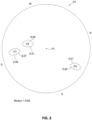
- the camera 10 can be any camera as long as it can photograph the sky. In this embodiment, an all-sky camera using a fisheye lens is set upwards to capture a wide area of the sky with a single camera, but it is not limited to this. If the camera 10 is placed vertically upward and horizontally, as shown in Fig. 2 , a center P1 of the sky image G1 obtained from the camera 10 is directly above (elevation angle 90 degrees), and the elevation angle decreases as the center P1 moves toward an edge of the image. If the orientation of the camera 10 is known, the orientation in the image is also known. That is, each pixel at an arbitrary position in the sky image has a known elevation angle and a known orientation. In the figure, the directions are shown as North (N), South (S), West (W) and East (E).
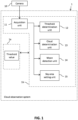
- the cloud observation system 1 has an acquisition unit 11 , a threshold determination unit 12 , and a cloud determination unit 13 .
- the cloud observation system 1 may have a moon detection unit 14 and a sky area setting unit 15 .
- These units 11 ⁇ 15 are realized in cooperation of software and hardware in a computer equipped with a processor 1b such as a CPU, storage 1a such as a memory, various interfaces, etc., by the processor 1b executing a program stored in the memory 1a beforehand.
- the acquisition unit 11 shown in Fig. 1 acquires at least one sky image.
- the camera 10 is preferably taken periodically to obtain sky images G1 , G2 .
- a period of photographing by the camera 10 can be set arbitrarily, for example, every minute, every 5 minutes, every hour, etc.
- the camera 10 needs to have a longer shutter speed compared to daytime.
- the shutter speed also affects the camera equipment, aperture, and other shooting conditions, such as 2.5 to 5 seconds. Since the way the sky image is captured also changes according to the shutter speed, it is preferable to take a plurality of pictures with the camera 10 at different shutter speeds to obtain a plurality of sky images each time the prescribed shooting timing comes. This is because a sky image with an appropriate shutter speed can be selected from the plurality of sky images.
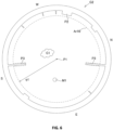
- the sky area setting unit 15 shown in Fig. 1 sets a sky area Ar10 in the sky image as shown in Fig. 6 .
- Fig. 6 illustrates the sky image G2 obtained from the all-sky camera 10 .
- the sky area setting unit 15 removes a fringe part of the sky image G1 from the sky area ArlO where the sky is visible.
- the fringe part means the area that lies outside the circle with a prescribed radius of ⁇ 1 from the directly above P1 of the sky image.
- the sky area ArlO is indicated by a dashed line.
- the method by which the sky area setting unit 15 sets the sky area Ar10 it may be specified based on the coordinates individually specified by the user in advance, or it may be automatically recognized.
- An example of an automatic method of recognition is taking the plurality of sky images in succession during the day and using the change in pixel values in the area where clouds flow.
- an area inside a circle of a prescribed radius, ⁇ 1 , in the sky image G2 , in which the change in pixel values is relatively large among the plurality of sky images is recognized as a sky area, Ar10 .
- a method for recognizing an area with relatively little change in pixel values as a non-sky area can be mentioned.
- the prescribed radius, ⁇ 1 can be changed appropriately depending on the performance of the camera. In the case of a fisheye lens, the larger the prescribed radius, ⁇ 1 , the greater the distortion of the image, so that it can be changed appropriately according to the performance of the camera.
- the threshold determination unit 12 shown in Fig. 1 determines the threshold value based on the pixel values of the plurality of edges in the sky image.
- the threshold value is used in the cloud determination unit 13 for cloud determination.
- FIG. 2 when sky image G1 shows clouds ( C1 , C2 , C3 ), the boundary between the sky and clouds can be detected as an edge.
- An edge is a pixel whose pixel value changes rapidly compared to surrounding pixels in a sky image.
- the edge detection method can utilize various known algorithms. For example, the differential value of the pixel value is used.
- the lightness difference based on the pixel value is used to determine whether or not the pixel is a cloud.
- the lightness (L) used in this embodiment is calculated by (the red value (R) of the pixel + the green value (G) of the pixel + the blue value (B) of the pixel)/3, but the formula for calculating the lightness can be changed variably.
- the threshold determination unit 12 determines a threshold value for each sky image.
- the threshold determination unit 12 determines the threshold value based on the pixel values (lightness) of the plurality of edges in the sky image. Specifically, as shown in Fig. 2 , the pixel values (lightness) of the plurality of edges, which are often the boundaries between clouds and sky, are calculated respectively, and statistical processing is performed on the plurality of pixel values (lightness) to determine the threshold value.
- a median of the plurality of pixel values (lightness) is used as the threshold value, but it is not limited to the median as statistical processing.
- the median value of each luminosity is 0.28 and the threshold value is determined to be 0.28. Since the figures do not illustrate the lightness of all edge pixels, some lightness values are illustrated for ease of understanding.
- Figs. 3 ⁇ 5 illustrate diagrams illustrating how the threshold value is determined based on an actual sky image.
- Fig. 3 illustrates the sky image acquired by the acquisition unit 11 in gray scale.
- Fig. 4 illustrates the edges extracted from the sky image shown in Fig. 3 in white.
- Fig. 5 illustrates the lightness of the extracted edge as a number in the figure and shows that the median value of the lightness is 0.28. As shown in Fig. 5 , it can be seen that the threshold value pixel value (lightness) varies depending on the location in the sky image.
- the threshold determination unit 12 is configured as follows.
- the threshold determination unit 12 extracts edges in the first sky image G1 taken at the first time point. If the number of extracted edges is less than a predetermined value, the threshold value determined based on the second sky image G2 taken at the second time point is adopted as the threshold value for the first sky image G1 .
- the second sky image G2 is an image taken at the same time on a different day from the shooting date of the first sky image G1 . This is because, on other days, it may be possible to detect edges exceeding a given value due to a mixture of clouds and sky, and at the same time, the threshold value conditions are considered to be the same or nearly the same.
- the same time in the same camera is preferable, but there may be a time difference.
- the time difference between the first time point and the second time point is preferably zero or smaller. However, it is possible to produce an effect even if there is a time lag of, say, 10 minutes. More preferably, within 2 minutes, preferably within 1 minute, more preferably within 10 seconds.
- the difference in days between the first sky image G1 and the second sky image G2 is preferably within seven days, more preferably within three days, and even more preferably within one day. This is because if the difference is one day, it is considered that there is little difference in the threshold value.
- the cloud determination unit 13 shown in Fig. 1 determines a pixel (hereinafter also referred to as cloud pixels) in which a cloud appears from a plurality of pixels constituting the sky image.
- the threshold determination unit 12 determines a threshold value based on the lightness of the pixel
- the cloud determination unit 13 determines a cloud pixel based on the lightness and threshold value of the pixel in the sky image.
- the cloud determination unit 13 determines that a pixel with a lightness of 0.28 or higher or a pixel with a lightness greater than 0.28 is a cloud pixel.
- one threshold value is used for the target range of the sky area Ar10 in the sky image.
- the moon detection unit 14 shown in Fig. 1 detects pixels indicating the moon M1 in the sky image.
- the pixels indicating the moon M1 are relatively the brightest compared to other pixels in the sky area. In the example of Fig. 6 , the lightness of the pixels in the area where the moon M1 is located becomes higher.
- the moon detection unit 14 calculates the lightness of all pixels in the sky area Ar10 and determines the highest pixel to be the one indicating the moon M1 .
- the target range from which the threshold determination unit 12 extracts edges and the target range from which the cloud determination unit 13 determines clouds are preferably the ranges from which the range of the moon is removed from the sky area Ar10 . This is to avoid the influence of moon pixels on the threshold value.
- Cloud observation method of the first embodiment The cloud observation method executed by the cloud observation system 1 is described with reference to Fig. 7 .
- step ST100 the acquisition unit 11 acquires the first sky image taken by the camera 10 .
- the sky area setting unit 15 sets the sky area Ar10 in the first sky image.
- the moon detection unit 14 detects the moon in the sky area Ar10 of the sky image.
- the moon area is removed from the sky area Ar10 to be the target area for threshold value determination and cloud determination.
- the threshold determination unit 12 extracts the edge of the target area.
- the threshold determination unit 12 adopts the threshold value determined based on the second sky image taken at the same time zone on a different day from the shooting date of the first sky image as the threshold value of the first sky image in step ST106 , and moves to the next step ST108 .
- the threshold determination unit 12 determines a threshold value based on the pixel values of the plurality of edges, and the process moves to the next step ST108 .
- the cloud determination unit 13 determines a pixel in which a cloud is reflected from a plurality of pixels constituting the sky image based on the pixel values and threshold values in the sky image.
- the cloud observation system 1 and method of the second embodiment are described.
- the same units as in the first embodiment are denoted by the same symbols, and the explanation is omitted.
- the cloud observation system 1 of the second embodiment further has an area setting unit 16 .
- the area setting unit 16 sets a plurality of areas ( A1 , A2 ... An ) for the sky image G2 (preferably the sky area Ar10 of the sky image G2 ) as shown in Fig. 9 .
- the shape by which the sky area Ar10 is divided into plurality of areas can also be changed arbitrarily.
- the threshold determination unit 12 determines threshold values for each of the plurality of areas A1 to A9 .
- the cloud determination unit 13 determines the pixels in which clouds in the area appear, using the threshold values of the areas A1 to A9 , respectively.
- the sky image is divided into plurality of areas A1 to A9 , a threshold value is determined for each area, and cloud pixels are determined for each area.
- the area A1 close to the moon ( M1 ) in the sky image G2 is easily brightened by the influence of the moon.
- the portion of sky image G2 that is far from the moon ( M1 ) (For example, area A7 , etc.) is unaffected by the moon and becomes relatively dark.
- the sky image G2 includes directions close to city lights (For example, N, W, S) and directions without city lights such as the sea (E).
- Directions without city lights, such as the sea are relatively dark compared to directions close to city lights. Therefore, in the sky image G2 , the lightness of clouds varies from place to place.
- the sky image G2 is divided into plurality of areas A1 to A9 , and the threshold value for each area is determined to determine the clouds for each area, the accuracy of cloud determination can be improved compared with the case where one threshold value is used for the whole sky image.
- the threshold values for each area are determined based on the pixel values of the edges in the plurality of areas A1 to A9 and the pixel values of the fringe part of the sky image G2 .
- the plurality of areas have area A1 (first area) containing the moon ( M1 ) and areas A2-A9 (second area) further away from the moon ( M1 ) than area A1 (first area).
- the threshold value 0.28 may be determined based on the pixel values of the edges in the plurality of areas ( A1 to A9 ) including the first and second areas, and the threshold value of the first area ( A1 ) and the threshold value of the second area ( A2 to A9 ) may be different.
- a threshold value of 0.28 may be calculated from the pixel values of the edges of all areas, and the threshold value of the first area ( A1 ) may be corrected in the bright direction to, for example, 0.29.
- the threshold value 0.28 calculated based on the plurality of areas ( A1 to A9 ) may be set as the threshold value of the first area ( A1 ), and the threshold value of the second area ( A2 to A9 ) may be corrected in the dark direction to, for example, 0.27.
- the area adjacent to the moon ( A10 , A11 , A12 ) may be designated as the first area, and the area further away from the moon ( M1 ) than the first area ( A10 , A11 , A12 ) ( A13 ) may be designated as the second area.
- the third embodiment does not have the area setting unit 16 for setting the plurality of areas.
- the threshold determination unit 12 determines the threshold value of each of the plural pixels constituting the sky image G1 based on the distance from the pixel to the edge and the pixel value of the edge.
- the cloud determination unit 13 determines using the threshold values of each pixel constituting the sky image. For example, as shown in Fig.
- the threshold value of a certain pixel ( U1 ) is calculated, the threshold value is calculated based on the distance from the pixel ( U1 ) to the edge ( d1 , d2 , d3 , d4 ) and the pixel value of the edge ( v1 , v2 , v3 , v4 ).
- the effect of edge pixel values (lightness) on a given pixel ( U1 ) is greater at closer distances and less at farther distances. Therefore, when determining the threshold value of a certain pixel ( U1 ), it is necessary to weight the pixel values of all edges by distance.
- the threshold value used for cloud determination is lightness, but it is not limited to this.
- a pixel value may be a monochromatic pixel value or a combination of pixel values as appropriate.
- the cloud observation system 1 of the first, second, and third embodiment consists of a sky image taken by the camera 10 that contains the sky ( G1 ; G2 ), the threshold determination unit 12 that determines a threshold value based on the pixel values of a plurality of edges in the sky image, and the cloud determination unit 13 that determines a pixel indicating a cloud from a plurality of pixels constituting the sky image based on the pixel values and threshold values in the sky image.
- the cloud observation methods of the first, second and third embodiment are to acquire a sky image taken by the camera 10 that contains the sky ( ST100 ) and to determine a threshold value based on the pixel values of the plurality of edges in the sky image ( ST107 ; ST106) and determining the pixels with clouds from the plurality of pixels composing the sky image based on the pixel values and threshold values in the sky image ( ST108 ).
- the edge in the sky image is often the boundary between the cloud and the sky, and the threshold value is determined based on the pixel values of the plurality of edges in the sky image. Therefore, the clouds can be identified and observed even at night when the color of the sky is not reflected by sunlight during the day.
- the threshold determination unit 12 determines the threshold value based on the lightness of the pixels of the plurality of edges
- the cloud determination unit 13 determines the pixel in which the cloud appears based on the lightness and threshold value of the pixels in the sky image.
- the area setting unit 16 for setting a plurality of areas ( A1 to A9 ; A10 to A13 ) for the sky image) is provided, the threshold determination unit 12 determines threshold value for each of the plurality of areas ( A1 to A9 ; A10 to A13 ), and it is preferable that the cloud determination unit 13 uses the threshold value of each area to determine the pixels in which clouds appear.
- sky images For example, areas of the sky image that are closer to the moon are more likely to brighten under the influence of the moon. Conversely, the portion of the sky image that is far from the moon is relatively dark without the influence of the moon. Sky images also include directions close to city lights and directions without city lights, such as the sea, which are relatively darker than directions close to city lights. Therefore, by setting the plurality of areas in the sky image and using a threshold value for each area, it is possible to improve the accuracy of determining clouds compared to using one threshold value for the entire sky image.
- the sky image G2 is an image taken by an all-sky camera, and it is preferable that the threshold determination unit 12 determines the threshold values of each of the areas ( A1 to A9 ) based on the pixel values of the edges in the plurality of areas and the pixel values of the peripheral of the sky image G2 .
- the moon detection unit 14 that detects pixels indicating the moon in the sky image G2 , and has the plurality of areas (A1 to A9 ; A10 to A13) including the first area ( A1 ; A10 to A12) containing or adjacent to the moon ( M1 ), and the second area ( A2 to A9 ; A13 ), which is farther from the moon than the first area, and the threshold determination unit 12 determines the threshold value of each area based on the pixel values of the edges in the plurality of areas including the first and second areas, and sets the threshold value of the first area and the threshold value of the second area to different values.
- the edge of the first area containing or adjacent to the moon is susceptible to moonlight and is likely to be bright. Therefore, while determining the threshold value based on the pixel values of the edges in the plurality of areas, the threshold values of the first and second areas are made different. As a result, the threshold value of the first area, which is susceptible to moonlight, and the threshold value of the second area, which is not susceptible to moonlight, can be set appropriately, and the cloud determination accuracy can be improved.
- the threshold determination unit 12 extracts a plurality of edges in the sky image G1 and determines the threshold values of each of the plurality of pixels constituting the sky image G1 based on the distance from the pixel to the edge ( d1 , d2 , d3 , d4 ) and the pixel value of the edge ( v1 , v2 , v3 , v4 ), and that the cloud determination unit 13 uses the threshold values of each of the pixels constituting the sky image G1 .
- Edges closer to a pixel have a greater impact on cloud judgment than edges farther from a pixel. Therefore, since the threshold value is determined based on the distance from the pixel to the edge and the pixel value of the edge, it becomes possible to improve the cloud determination accuracy compared with the case where the threshold value is determined uniformly.
- the moon detection unit 14 is provided to detect pixels indicating the moon in the sky image, and the threshold determination unit 12 extracts the edge by removing the range of the moon from the target range from which the edge is extracted.
- the acquisition unit 11 acquires the first sky image.
- a threshold value determined based on the second sky image photographed at the same time zone on a different day from the date and time of the first sky image is adopted as the threshold value of the first sky image.
- the sky area in the first sky image is either all cloudy or all clear, and the threshold value cannot be determined. Therefore, since the threshold value of the second sky image in the same time zone of another day is used, which is considered to have almost the same threshold value condition, the clouds in the first sky image can be judged appropriately.
- the sky image is an image taken by an all-sky camera as in the first, second and third embodiment, and the threshold determination unit 12 extracts the edge by removing the fringe part of the sky image from the target area from which the edge is extracted.
- the edge of the sky image obtained from an all-sky camera using a fisheye lens which is likely to show city lights themselves, is removed from the target range of edge extraction, so that an appropriate threshold value can be determined, and cloud determination accuracy can be improved.
- the program according to this embodiment is a program that causes a computer (one or more processors) to execute the above method.
- a temporary recording medium readable by a computer according to this embodiment stores the above program.
- Each unit 11 - 15 shown in Fig. 1 is realized by executing a predetermined program by the cloud observation system 1 or a processor, but each unit may be configured by a dedicated memory or a dedicated circuit.
- the units 11 - 15 are implemented in the processor 1b of one computer, but the units 11 - 15 may be distributed and implemented in a plurality of computers or clouds. That is, the above method may be performed by one or more processors.
- each unit 11 ⁇ 15 is implemented for illustrative purposes, but these units can be omitted arbitrarily.
Landscapes
- Engineering & Computer Science (AREA)
- Physics & Mathematics (AREA)
- General Physics & Mathematics (AREA)
- Theoretical Computer Science (AREA)
- Multimedia (AREA)
- Computer Vision & Pattern Recognition (AREA)
- Environmental & Geological Engineering (AREA)
- Software Systems (AREA)
- Life Sciences & Earth Sciences (AREA)
- Atmospheric Sciences (AREA)
- Biodiversity & Conservation Biology (AREA)
- Ecology (AREA)
- Environmental Sciences (AREA)
- Astronomy & Astrophysics (AREA)
- Remote Sensing (AREA)
- Image Analysis (AREA)
- Image Processing (AREA)
Abstract
Description
- This disclosure relates to cloud observation systems, cloud observation methods, and programs.
- It is known to use ground-based all-sky cameras as cloud observation methods. For example,
Patent Document 1 states that clouds are observed based on sky images captured by an all-sky camera. - Patent Document 1: International Publication No.
2019/244510 - Nighttime cloud observation methods using cameras are required. However, the algorithm for determining clouds and sky described in
Patent Document 1 cannot be used at night. - The present disclosure provides cloud observation systems, methods and programs that enable night clouds to be observed by cameras.
- The cloud observation system of the present disclosure is provided with an acquisition unit that acquires a sky image taken by a camera that contains the sky, a threshold determination unit that determines a threshold value based on the pixel values of a plurality of edges in the sky image, and a cloud determination unit that determines a pixel which contains a cloud from a plurality of pixels constituting the sky image based on the pixel values in the sky image and the threshold value.
-
-
Fig. 1 is a block diagram illustrating the configuration of the cloud observation system of a first embodiment; -
Fig. 2 is an explanatory diagram for a sky image taken by a camera; -
Fig. 3 illustrates an actual sky image in grayscale; -
Fig. 4 illustrates edges extracted from the sky image shown inFig. 3 in white; -
Fig. 5 illustrates the lightness of the extracted edge with a number in the figure and showing the median value of the lightness; -
Fig. 6 illustrates an example of a sky image obtained from an all-sky camera; -
Fig. 7 is a flow chart illustrating the processing performed by the cloud observation system of the first embodiment; -
Fig. 8 is a block diagram illustrating the configuration of a cloud observation system of a second embodiment; -
Fig. 9 illustrates a plurality of areas set in a sky image; -
Fig. 10 is an explanatory diagram of the method of determining the threshold values for each of the plurality of areas; -
Fig. 11 is an explanatory diagram of the method of determining the threshold values for each of the plurality of areas; -
Fig. 12 is an explanatory diagram of the method of determining the threshold values for each of the plurality of areas; and -
Fig. 13 is an explanatory diagram of the method for determining the threshold value of each pixel of the sky image in a third embodiment. - Example apparatus are described herein. Other example embodiments or features may further be utilized, and other changes may be made, without departing from the spirit or scope of the subject matter presented herein. In the following detailed description, reference is made to the accompanying drawings, which form a part thereof.
- The example embodiments described herein are not meant to be limiting. It will be readily understood that the aspects of the present disclosure, as generally described herein, and illustrated in the drawings, can be arranged, substituted, combined, separated, and designed in a wide variety of different configurations, all of which are explicitly contemplated herein.
- The cloud observation system of a first embodiment of the present disclosure is described below with reference to the drawings.
- The
cloud observation system 1 of the first embodiment processes sky images G1, G2 taken by at least onecamera 10. The sky image contains the sky. Thecamera 10 can be any camera as long as it can photograph the sky. In this embodiment, an all-sky camera using a fisheye lens is set upwards to capture a wide area of the sky with a single camera, but it is not limited to this. If thecamera 10 is placed vertically upward and horizontally, as shown inFig. 2 , a center P1 of the sky image G1 obtained from thecamera 10 is directly above (elevation angle 90 degrees), and the elevation angle decreases as the center P1 moves toward an edge of the image. If the orientation of thecamera 10 is known, the orientation in the image is also known. That is, each pixel at an arbitrary position in the sky image has a known elevation angle and a known orientation. In the figure, the directions are shown as North (N), South (S), West (W) and East (E). - As shown in
Fig. 1 , thecloud observation system 1 has anacquisition unit 11, athreshold determination unit 12, and acloud determination unit 13. Thecloud observation system 1 may have amoon detection unit 14 and a skyarea setting unit 15. Theseunits 11 ~ 15 are realized in cooperation of software and hardware in a computer equipped with aprocessor 1b such as a CPU,storage 1a such as a memory, various interfaces, etc., by theprocessor 1b executing a program stored in thememory 1a beforehand. - The
acquisition unit 11 shown inFig. 1 acquires at least one sky image. For cloud observation, thecamera 10 is preferably taken periodically to obtain sky images G1, G2. A period of photographing by thecamera 10 can be set arbitrarily, for example, every minute, every 5 minutes, every hour, etc. When shooting at night, thecamera 10 needs to have a longer shutter speed compared to daytime. The shutter speed also affects the camera equipment, aperture, and other shooting conditions, such as 2.5 to 5 seconds. Since the way the sky image is captured also changes according to the shutter speed, it is preferable to take a plurality of pictures with thecamera 10 at different shutter speeds to obtain a plurality of sky images each time the prescribed shooting timing comes. This is because a sky image with an appropriate shutter speed can be selected from the plurality of sky images. - The sky
area setting unit 15 shown inFig. 1 sets a sky area Ar10 in the sky image as shown inFig. 6. Fig. 6 illustrates the sky image G2 obtained from the all-sky camera 10. As shown inFig. 6 , in the periphery of the sky image G2 obtained from the all-sky camera 10, there are cases where city buildings surrounding the all-sky camera 10, city lights, obstacles, and other non-sky objects P2 appear. Therefore, the skyarea setting unit 15 removes a fringe part of the sky image G1 from the sky area ArlO where the sky is visible. The fringe part means the area that lies outside the circle with a prescribed radius of ϕ1 from the directly above P1 of the sky image. In addition, when an obstacle P3 is not in the periphery but is reflected, the obstacle P3 is also removed from the sky area Ar10. InFig. 6 , the sky area ArlO is indicated by a dashed line. As the method by which the skyarea setting unit 15 sets the sky area Ar10, it may be specified based on the coordinates individually specified by the user in advance, or it may be automatically recognized. An example of an automatic method of recognition is taking the plurality of sky images in succession during the day and using the change in pixel values in the area where clouds flow. Specifically, an area inside a circle of a prescribed radius, ϕ1, in the sky image G2, in which the change in pixel values is relatively large among the plurality of sky images is recognized as a sky area, Ar10. Conversely, a method for recognizing an area with relatively little change in pixel values as a non-sky area can be mentioned. The prescribed radius, ϕ1, can be changed appropriately depending on the performance of the camera. In the case of a fisheye lens, the larger the prescribed radius, ϕ1, the greater the distortion of the image, so that it can be changed appropriately according to the performance of the camera. - The
threshold determination unit 12 shown inFig. 1 determines the threshold value based on the pixel values of the plurality of edges in the sky image. The threshold value is used in thecloud determination unit 13 for cloud determination. As shown inFig. 2 , when sky image G1 shows clouds (C1, C2, C3), the boundary between the sky and clouds can be detected as an edge. An edge is a pixel whose pixel value changes rapidly compared to surrounding pixels in a sky image. The edge detection method can utilize various known algorithms. For example, the differential value of the pixel value is used. - During the day, clouds are white and the sky is blue due to sunlight refraction, so it is possible to determine clouds by comparing their blueness. But at night, in the absence of sunlight, blue comparisons can't detect clouds. At night, the clouds are brighter than the sky because the moonlight and city lights are reflected back by the clouds and reach the
camera 10. Therefore, in this embodiment, the lightness difference based on the pixel value is used to determine whether or not the pixel is a cloud. The lightness (L) used in this embodiment is calculated by (the red value (R) of the pixel + the green value (G) of the pixel + the blue value (B) of the pixel)/3, but the formula for calculating the lightness can be changed variably. - Since there is a high possibility that the threshold value of the pixel value (lightness) for distinguishing the cloud from the sky is different for each sky image, the
threshold determination unit 12 determines a threshold value for each sky image. Thethreshold determination unit 12 determines the threshold value based on the pixel values (lightness) of the plurality of edges in the sky image. Specifically, as shown inFig. 2 , the pixel values (lightness) of the plurality of edges, which are often the boundaries between clouds and sky, are calculated respectively, and statistical processing is performed on the plurality of pixel values (lightness) to determine the threshold value. In this embodiment, a median of the plurality of pixel values (lightness) is used as the threshold value, but it is not limited to the median as statistical processing. For example, it may be mean or frequency. The median can be used to determine an appropriate threshold value without noise, such as a jump. In the example shown inFig. 2 , an edge of cloud C1 has a portion with luminosity = 0.27 and another portion with luminosity = 0.30. An edge of cloud C2 has a portion with luminosity = 0.28 and another portion with luminosity = 0.31. An edge of cloud C3 has a portion with luminosity = 0.27 and another portion with luminosity = 0.28. In this case, the median value of each luminosity is 0.28 and the threshold value is determined to be 0.28. Since the figures do not illustrate the lightness of all edge pixels, some lightness values are illustrated for ease of understanding. -
Figs. 3 ~ 5 illustrate diagrams illustrating how the threshold value is determined based on an actual sky image.Fig. 3 illustrates the sky image acquired by theacquisition unit 11 in gray scale.Fig. 4 illustrates the edges extracted from the sky image shown inFig. 3 in white.Fig. 5 illustrates the lightness of the extracted edge as a number in the figure and shows that the median value of the lightness is 0.28. As shown inFig. 5 , it can be seen that the threshold value pixel value (lightness) varies depending on the location in the sky image. - If the sky area Ar10 in the sky image contains almost all clouds or almost all clear sky, no edges are detected or fewer edges are detected. In this case, the threshold value cannot be determined based on the pixel values of the plurality of edges. Therefore, in the first embodiment, the
threshold determination unit 12 is configured as follows. - That is, the
threshold determination unit 12 extracts edges in the first sky image G1 taken at the first time point. If the number of extracted edges is less than a predetermined value, the threshold value determined based on the second sky image G2 taken at the second time point is adopted as the threshold value for the first sky image G1. The second sky image G2 is an image taken at the same time on a different day from the shooting date of the first sky image G1. This is because, on other days, it may be possible to detect edges exceeding a given value due to a mixture of clouds and sky, and at the same time, the threshold value conditions are considered to be the same or nearly the same. Here, for the same time zone, for example, the same time in the same camera is preferable, but there may be a time difference. The time difference between the first time point and the second time point is preferably zero or smaller. However, it is possible to produce an effect even if there is a time lag of, say, 10 minutes. More preferably, within 2 minutes, preferably within 1 minute, more preferably within 10 seconds. The difference in days between the first sky image G1 and the second sky image G2 is preferably within seven days, more preferably within three days, and even more preferably within one day. This is because if the difference is one day, it is considered that there is little difference in the threshold value. - When a plurality of second sky images exist, it is preferable to select a second sky image having the same moon age as the first sky image or the closest moon age from the plurality of second sky images. This is because the phases of the moon will be the same or similar, and the lightness of the clouds by the moon will be the same or similar.
- Based on the pixel values and threshold values in the sky image, the
cloud determination unit 13 shown inFig. 1 determines a pixel (hereinafter also referred to as cloud pixels) in which a cloud appears from a plurality of pixels constituting the sky image. In this embodiment, thethreshold determination unit 12 determines a threshold value based on the lightness of the pixel, and thecloud determination unit 13 determines a cloud pixel based on the lightness and threshold value of the pixel in the sky image. In the examples ofFig. 2 andFig. 5 , since the threshold value is 0.28, thecloud determination unit 13 determines that a pixel with a lightness of 0.28 or higher or a pixel with a lightness greater than 0.28 is a cloud pixel. In this embodiment, one threshold value is used for the target range of the sky area Ar10 in the sky image. - The
moon detection unit 14 shown inFig. 1 detects pixels indicating the moon M1 in the sky image. The pixels indicating the moon M1 are relatively the brightest compared to other pixels in the sky area. In the example ofFig. 6 , the lightness of the pixels in the area where the moon M1 is located becomes higher. Themoon detection unit 14 calculates the lightness of all pixels in the sky area Ar10 and determines the highest pixel to be the one indicating the moon M1. When themoon detection unit 14 is implemented, the target range from which thethreshold determination unit 12 extracts edges and the target range from which thecloud determination unit 13 determines clouds are preferably the ranges from which the range of the moon is removed from the sky area Ar10. This is to avoid the influence of moon pixels on the threshold value. - Cloud observation method of the first embodiment. The cloud observation method executed by the
cloud observation system 1 is described with reference toFig. 7 . - First, in step ST100, the
acquisition unit 11 acquires the first sky image taken by thecamera 10. In the next step ST101, the skyarea setting unit 15 sets the sky area Ar10 in the first sky image. In the next step ST102, themoon detection unit 14 detects the moon in the sky area Ar10 of the sky image. In the next step ST103, the moon area is removed from the sky area Ar10 to be the target area for threshold value determination and cloud determination. Then, in step ST104, thethreshold determination unit 12 extracts the edge of the target area. If the number of edges of the target area is equal to or less than a predetermined value (ST105: YES), thethreshold determination unit 12 adopts the threshold value determined based on the second sky image taken at the same time zone on a different day from the shooting date of the first sky image as the threshold value of the first sky image in step ST106, and moves to the next step ST108. On the other hand, when the number of edges of the target area is not less than a predetermined value (ST105: NO), in step ST107, thethreshold determination unit 12 determines a threshold value based on the pixel values of the plurality of edges, and the process moves to the next step ST108. In step ST108, thecloud determination unit 13 determines a pixel in which a cloud is reflected from a plurality of pixels constituting the sky image based on the pixel values and threshold values in the sky image. - The
cloud observation system 1 and method of the second embodiment are described. The same units as in the first embodiment are denoted by the same symbols, and the explanation is omitted. As shown inFig. 8 , thecloud observation system 1 of the second embodiment further has anarea setting unit 16. Thearea setting unit 16 sets a plurality of areas (A1, A2 ... An) for the sky image G2 (preferably the sky area Ar10 of the sky image G2) as shown inFig. 9 . n is a natural number greater than or equal to 2. In the example ofFig. 9 , n = 9, but the number of areas can be changed accordingly. The shape by which the sky area Ar10 is divided into plurality of areas can also be changed arbitrarily. Thethreshold determination unit 12 determines threshold values for each of the plurality of areas A1 to A9. Thecloud determination unit 13 determines the pixels in which clouds in the area appear, using the threshold values of the areas A1 to A9, respectively. - That is, in the first embodiment, only one threshold value is determined for the sky image, and clouds are determined by one threshold value. In contrast, in the second embodiment, the sky image is divided into plurality of areas A1 to A9, a threshold value is determined for each area, and cloud pixels are determined for each area.
- For example, as shown in
Fig. 9 , the area A1 close to the moon (M1) in the sky image G2 is easily brightened by the influence of the moon. Conversely, the portion of sky image G2 that is far from the moon (M1) (For example, area A7, etc.) is unaffected by the moon and becomes relatively dark. In addition, the sky image G2 includes directions close to city lights (For example, N, W, S) and directions without city lights such as the sea (E). Directions without city lights, such as the sea, are relatively dark compared to directions close to city lights. Therefore, in the sky image G2, the lightness of clouds varies from place to place. Therefore, since the sky image G2 is divided into plurality of areas A1 to A9, and the threshold value for each area is determined to determine the clouds for each area, the accuracy of cloud determination can be improved compared with the case where one threshold value is used for the whole sky image. - Specific methods for determining the threshold value are as follows:
- (1) For each area A1 to A9, the threshold value may be determined based on the pixel value (lightness) of the edge within the area,
- (2) The first threshold value may be determined based on the pixel values (lightness) of all edges within the target range of the sky area Ar10 (within plurality of areas A1 to A9), and the threshold value of each area A1 to A9 may be determined by correcting the first threshold value according to the orientation corresponding to the area. For example, if east (E) is dark and northwest (N, W) is light, the value obtained by subtracting the value corresponding to east (E) from the first threshold value may be used as the threshold value for area A2, and the value obtained by adding the value corresponding to northwest (N, W) from the first threshold value may be used as the threshold value for areas A6 to A9. In this case, the correction value corresponding to the bearing is preset, and
- (3) The first threshold value may be determined based on the pixel values (lightness) of all edges within the target range of the sky area Ar10, and the threshold values of each area A1 to A9 may be determined by correcting the first threshold value with a correction value corresponding to the pixel values (lightness) of the peripheral area corresponding to the area. For example, the threshold value of area A7 is determined by correcting the first threshold value with a correction value corresponding to the pixel value of the outer periphery of area A6 (the pixel value of the northern periphery).
- That is, when the above (2) and (3) are put together, the threshold values for each area are determined based on the pixel values of the edges in the plurality of areas A1 to A9 and the pixel values of the fringe part of the sky image G2.
- (4) As shown in
Fig. 10 , the plurality of areas have area A1 (first area) containing the moon (M1) and areas A2-A9 (second area) further away from the moon (M1) than area A1 (first area). The threshold value 0.28 may be determined based on the pixel values of the edges in the plurality of areas (A1 to A9) including the first and second areas, and the threshold value of the first area (A1) and the threshold value of the second area (A2 to A9) may be different. As an example of a specific calculation method, a threshold value of 0.28 may be calculated from the pixel values of the edges of all areas, and the threshold value of the first area (A1) may be corrected in the bright direction to, for example, 0.29. As shown inFig. 11 , the threshold value 0.28 calculated based on the plurality of areas (A1 to A9) may be set as the threshold value of the first area (A1), and the threshold value of the second area (A2 to A9) may be corrected in the dark direction to, for example, 0.27. - (5) As shown in
Fig. 12 , when the plurality of areas (A10 to A13) are set except for the moon (M1), the area adjacent to the moon (A10, A11, A12) may be designated as the first area, and the area further away from the moon (M1) than the first area (A10, A11, A12) (A13) may be designated as the second area. - Like the first embodiment shown in
Fig. 1 , the third embodiment does not have thearea setting unit 16 for setting the plurality of areas. As shown inFig. 13 , thethreshold determination unit 12 determines the threshold value of each of the plural pixels constituting the sky image G1 based on the distance from the pixel to the edge and the pixel value of the edge. Thecloud determination unit 13 determines using the threshold values of each pixel constituting the sky image. For example, as shown inFig. 13 , when the threshold value of a certain pixel (U1) is calculated, the threshold value is calculated based on the distance from the pixel (U1) to the edge (d1, d2, d3, d4) and the pixel value of the edge (v1, v2, v3, v4). The effect of edge pixel values (lightness) on a given pixel (U1) is greater at closer distances and less at farther distances. Therefore, when determining the threshold value of a certain pixel (U1), it is necessary to weight the pixel values of all edges by distance. This makes it possible to increase the influence of the pixel value of an edge with a short distance from a certain pixel (U1) and to reduce the influence of the pixel value of an edge with a long distance from a certain pixel (U1). With this method, the accuracy of the threshold value can be greatly improved, although the computational cost increases. - In the above embodiment, the threshold value used for cloud determination is lightness, but it is not limited to this. For example, a pixel value may be a monochromatic pixel value or a combination of pixel values as appropriate.
- As described above, the
cloud observation system 1 of the first, second, and third embodiment consists of a sky image taken by thecamera 10 that contains the sky (G1; G2), thethreshold determination unit 12 that determines a threshold value based on the pixel values of a plurality of edges in the sky image, and thecloud determination unit 13 that determines a pixel indicating a cloud from a plurality of pixels constituting the sky image based on the pixel values and threshold values in the sky image. - The cloud observation methods of the first, second and third embodiment are to acquire a sky image taken by the
camera 10 that contains the sky (ST100) and to determine a threshold value based on the pixel values of the plurality of edges in the sky image (ST107; ST106) and determining the pixels with clouds from the plurality of pixels composing the sky image based on the pixel values and threshold values in the sky image (ST108). - In this way, the edge in the sky image is often the boundary between the cloud and the sky, and the threshold value is determined based on the pixel values of the plurality of edges in the sky image. Therefore, the clouds can be identified and observed even at night when the color of the sky is not reflected by sunlight during the day.
- Although not particularly limited, as in the first, second and third embodiment, it is preferable that the
threshold determination unit 12 determines the threshold value based on the lightness of the pixels of the plurality of edges, and thecloud determination unit 13 determines the pixel in which the cloud appears based on the lightness and threshold value of the pixels in the sky image. - With this configuration, it is possible to improve the accuracy of cloud determination compared to, for example, determining clouds based on single-color pixel values.
- Although not particularly limited, as in the second embodiment, the
area setting unit 16 for setting a plurality of areas (A1 to A9; A10 to A13) for the sky image) is provided, thethreshold determination unit 12 determines threshold value for each of the plurality of areas (A1 to A9; A10 to A13), and it is preferable that thecloud determination unit 13 uses the threshold value of each area to determine the pixels in which clouds appear. - For example, areas of the sky image that are closer to the moon are more likely to brighten under the influence of the moon. Conversely, the portion of the sky image that is far from the moon is relatively dark without the influence of the moon. Sky images also include directions close to city lights and directions without city lights, such as the sea, which are relatively darker than directions close to city lights. Therefore, by setting the plurality of areas in the sky image and using a threshold value for each area, it is possible to improve the accuracy of determining clouds compared to using one threshold value for the entire sky image.
- Although not particularly limited, as in the second embodiment shown in
Fig. 9 , the sky image G2 is an image taken by an all-sky camera, and it is preferable that thethreshold determination unit 12 determines the threshold values of each of the areas (A1 to A9) based on the pixel values of the edges in the plurality of areas and the pixel values of the peripheral of the sky image G2. - In this way, not only the pixel values of the edges in the plurality of areas, but also the pixel values of the periphery of the sky image, where city lights and the like may be visible, are used to determine the threshold value for each area, so that the threshold value can be determined in consideration of city lights and cloud determination accuracy can be improved.
- Although not particularly limited, as in the second embodiment shown in
Fig. 10 ~ 12, it is equipped with themoon detection unit 14 that detects pixels indicating the moon in the sky image G2, and has the plurality of areas (A1 to A9; A10 to A13) including the first area (A1; A10 to A12) containing or adjacent to the moon (M1), and the second area (A2 to A9; A13), which is farther from the moon than the first area, and thethreshold determination unit 12 determines the threshold value of each area based on the pixel values of the edges in the plurality of areas including the first and second areas, and sets the threshold value of the first area and the threshold value of the second area to different values. - The edge of the first area containing or adjacent to the moon is susceptible to moonlight and is likely to be bright. Therefore, while determining the threshold value based on the pixel values of the edges in the plurality of areas, the threshold values of the first and second areas are made different. As a result, the threshold value of the first area, which is susceptible to moonlight, and the threshold value of the second area, which is not susceptible to moonlight, can be set appropriately, and the cloud determination accuracy can be improved.
- Although not particularly limited, as in the third embodiment, it is preferable that the
threshold determination unit 12 extracts a plurality of edges in the sky image G1 and determines the threshold values of each of the plurality of pixels constituting the sky image G1 based on the distance from the pixel to the edge (d1, d2, d3, d4) and the pixel value of the edge (v1, v2, v3, v4), and that thecloud determination unit 13 uses the threshold values of each of the pixels constituting the sky image G1. - Edges closer to a pixel have a greater impact on cloud judgment than edges farther from a pixel. Therefore, since the threshold value is determined based on the distance from the pixel to the edge and the pixel value of the edge, it becomes possible to improve the cloud determination accuracy compared with the case where the threshold value is determined uniformly.
- Although not particularly limited, as in the first, second and third embodiment, it is preferable that the
moon detection unit 14 is provided to detect pixels indicating the moon in the sky image, and thethreshold determination unit 12 extracts the edge by removing the range of the moon from the target range from which the edge is extracted. - With this configuration, the range of the moon that affects the determination of the threshold value is removed, and edges are extracted, which makes it possible to improve the accuracy of cloud determination.
- Although not particularly limited, as in the first, second and third embodiment, the
acquisition unit 11 acquires the first sky image. When the number of edges extracted based on the acquired first sky image is equal to or less than a predetermined value, a threshold value determined based on the second sky image photographed at the same time zone on a different day from the date and time of the first sky image is adopted as the threshold value of the first sky image. - If the number of edges is less than the prescribed value, the sky area in the first sky image is either all cloudy or all clear, and the threshold value cannot be determined. Therefore, since the threshold value of the second sky image in the same time zone of another day is used, which is considered to have almost the same threshold value condition, the clouds in the first sky image can be judged appropriately.
- Although not particularly limited, it is preferable that the sky image is an image taken by an all-sky camera as in the first, second and third embodiment, and the
threshold determination unit 12 extracts the edge by removing the fringe part of the sky image from the target area from which the edge is extracted. - With this configuration, the edge of the sky image obtained from an all-sky camera using a fisheye lens, which is likely to show city lights themselves, is removed from the target range of edge extraction, so that an appropriate threshold value can be determined, and cloud determination accuracy can be improved.
- The program according to this embodiment is a program that causes a computer (one or more processors) to execute the above method. In addition, a temporary recording medium readable by a computer according to this embodiment stores the above program.
- As described above, the embodiment of the present disclosure has been described based on the drawings, but the specific configuration should not be considered to be limited to these embodiments. The scope of this disclosure is indicated by the claims as well as by the description of the above embodiment, and further includes all modifications within the meaning and scope of the claims.
- For example, the execution order of each process, such as operations, procedures, steps, and steps in the devices, systems, programs, and methods presented in the claims, description, and drawings, can be realized in any order unless the output of the previous process is used in the later process. The use of "first," "second," etc., for convenience in describing the flow in the claims, the description, and the drawings does not mean that it is mandatory to carry out the procedures in this order.
- Each unit 11 - 15 shown in
Fig. 1 is realized by executing a predetermined program by thecloud observation system 1 or a processor, but each unit may be configured by a dedicated memory or a dedicated circuit. - In the
cloud observation system 1 of the above embodiment, the units 11 - 15 are implemented in theprocessor 1b of one computer, but the units 11 - 15 may be distributed and implemented in a plurality of computers or clouds. That is, the above method may be performed by one or more processors. - It is possible to adopt the structure adopted in each of the above embodiment to any other embodiment. In
Fig. 1 , eachunit 11 ~ 15 is implemented for illustrative purposes, but these units can be omitted arbitrarily. - The specific configuration of each unit is not limited to the above described embodiments, and various variations are possible without departing from the purpose of this disclosure.
-
- 1 Cloud observation system
- 1a Memory
- 1b Processor
- 10 Camera
- 11 Acquisition unit
- 12 Threshold determination unit
- 13 Cloud determination unit
- 14 Moon detection unit
- 15 Sky area setting unit
- 16 Area Setting unit
Claims (11)
- A cloud observation system, comprising:an acquisition unit configured to acquire a sky image taken by a camera that contains the sky, anda threshold determination unit configured to determine a threshold value based on a plurality of pixel values of a plurality of edges in the sky image; anda cloud determination unit configured to determine a pixel indicating a cloud from a plurality of pixels constituting the sky image based on the threshold value and the plurality of pixel values in the sky image.
- The cloud observation system according to claim 1, wherein:the threshold determination unit determines the threshold value based on a lightness of the plurality of pixels of the plurality of edges, andthe cloud determination unit determines the pixel indicating the cloud based on the lightness of the pixel in the sky image and the threshold value.
- The cloud observation system according to claim 1 or 2, further comprising:
an area setting unit configured to set a plurality of areas in the sky image, wherein:the threshold determination unit determines a plurality of threshold values of each of the plurality of areas, andthe cloud determination unit determines the pixel indicating the cloud using the plurality of threshold values for each of the plurality of areas. - The cloud observation system according to claim 3, wherein:the sky image is an image taken by an all-sky camera, andthe threshold determination unit determines the plurality of threshold values of each of the plurality of areas based on the plurality of pixel values of the plurality of edges in the plurality of areas and the plurality of pixel values of a fringe part of the sky image.
- The cloud observation system according to claims 3 or 4, further comprising:
a moon detection unit configured to detect pixels indicating a moon in the sky image, wherein:the plurality of areas includes a first area indicating or adjacent to the moon and a second area further away from the moon than the first area, andthe threshold determination unit determines the threshold values of each of the areas based on the pixel values of the edges in a plurality of areas including the first area and the second area and sets the threshold values of the first area and the second area to different values. - The cloud observation system according to claim 1 or 2, wherein:the threshold determination unit extracts a plurality of edges in the sky image and determines the threshold values for each of the plurality of pixels constituting the sky image based on a distance from the pixel to the edge and the pixel value of the edge, andthe cloud determination unit determines using threshold values of each pixel constituting the sky image.
- The cloud observation system according to any one of claims 1 to 6, wherein:the moon detection unit configured to detect pixels indicating the moon in the sky image, andthe threshold determination unit extracts the edge by removing a range of the moon from a target range for extracting edges.
- The cloud observation system according to any one of claims 1 to 7, wherein:the acquisition unit acquires a first sky image, andthe threshold determination unit adopts the threshold value determined based on a second sky image taken at the same time zone on a different day from the date and time of taking the first sky image as the threshold value of the first sky image when the number of edges extracted based on the acquired first sky image is equal to or less than a predetermined value.
- The cloud observation system according to any one of claims 1 to 8, wherein:the sky image is an image taken by an all-sky camera, andthe threshold determination unit extracts the edge by removing the fringe part of the sky image from a target range for extracting edges.
- A cloud observation method, comprising:acquiring a sky image taken by a camera that contains the sky, anddetermining a threshold value based on a plurality of pixel values of a plurality of edges in the sky image; anddetermining a pixel indicating a cloud from a plurality of pixels constituting the sky image based on the threshold value and the plurality of pixel values in the sky image.
- A non-transitory computer-readable medium having stored thereon computer-executable instructions which, when executed by a computer, cause the computer to execute the cloud observation method according to claim 10.
Applications Claiming Priority (2)
| Application Number | Priority Date | Filing Date | Title |
|---|---|---|---|
| JP2020136362 | 2020-08-12 | ||
| PCT/JP2021/026180 WO2022034764A1 (en) | 2020-08-12 | 2021-07-12 | Cloud observation system, cloud observation method, and program |
Publications (2)
| Publication Number | Publication Date |
|---|---|
| EP4198579A1 true EP4198579A1 (en) | 2023-06-21 |
| EP4198579A4 EP4198579A4 (en) | 2024-06-26 |
Family
ID=80247179
Family Applications (1)
| Application Number | Title | Priority Date | Filing Date |
|---|---|---|---|
| EP21855843.5A Pending EP4198579A4 (en) | 2020-08-12 | 2021-07-12 | Cloud observation system, cloud observation method, and program |
Country Status (4)
| Country | Link |
|---|---|
| US (1) | US20230177803A1 (en) |
| EP (1) | EP4198579A4 (en) |
| JP (1) | JP7695940B2 (en) |
| WO (1) | WO2022034764A1 (en) |
Families Citing this family (1)
| Publication number | Priority date | Publication date | Assignee | Title |
|---|---|---|---|---|
| WO2020179326A1 (en) * | 2019-03-06 | 2020-09-10 | 古野電気株式会社 | Cloud observation device, cloud observation method, and program |
Family Cites Families (11)
| Publication number | Priority date | Publication date | Assignee | Title |
|---|---|---|---|---|
| JPH05333160A (en) * | 1992-05-29 | 1993-12-17 | Sony Corp | Cloud amount measuring method and device |
| JP3593567B2 (en) * | 2002-05-14 | 2004-11-24 | 独立行政法人情報通信研究機構 | Night cloud amount measuring method and night cloud amount measuring device |
| JP5752993B2 (en) | 2011-05-23 | 2015-07-22 | オリンパス株式会社 | Image processing apparatus and image processing program |
| WO2015157643A1 (en) * | 2014-04-10 | 2015-10-15 | Vega-Avila Rolando | Solar energy forecasting |
| US9792522B2 (en) | 2015-12-01 | 2017-10-17 | Bloomsky, Inc. | Weather information extraction using sequential images |
| JP6541612B2 (en) | 2016-04-25 | 2019-07-10 | 三菱電機株式会社 | Image processing apparatus and image processing method |
| WO2017193153A1 (en) | 2016-05-11 | 2017-11-16 | Commonwealth Scientific And Industrial Research Organisation | Solar power forecasting |
| CN112292620B (en) | 2018-06-19 | 2023-06-06 | 古野电气株式会社 | Cloud observation device, cloud observation system, cloud observation method, and storage medium |
| WO2020080373A1 (en) | 2018-10-15 | 2020-04-23 | 国立研究開発法人宇宙航空研究開発機構 | Optical ground station operational management system, optical operation planning device, and optical ground station operational management method and program |
| JP7264428B2 (en) | 2018-12-17 | 2023-04-25 | 国立大学法人秋田大学 | Road sign recognition device and its program |
| JP7175188B2 (en) | 2018-12-28 | 2022-11-18 | 株式会社デンソーテン | Attached matter detection device and attached matter detection method |
-
2021
- 2021-07-12 EP EP21855843.5A patent/EP4198579A4/en active Pending
- 2021-07-12 WO PCT/JP2021/026180 patent/WO2022034764A1/en not_active Ceased
- 2021-07-12 JP JP2022542604A patent/JP7695940B2/en active Active
-
2023
- 2023-01-30 US US18/161,700 patent/US20230177803A1/en active Pending
Also Published As
| Publication number | Publication date |
|---|---|
| US20230177803A1 (en) | 2023-06-08 |
| EP4198579A4 (en) | 2024-06-26 |
| JPWO2022034764A1 (en) | 2022-02-17 |
| JP7695940B2 (en) | 2025-06-19 |
| WO2022034764A1 (en) | 2022-02-17 |
Similar Documents
| Publication | Publication Date | Title |
|---|---|---|
| US11989907B2 (en) | Cloud observation device, cloud observation method, and program | |
| US20200043225A1 (en) | Image processing apparatus and control method thereof | |
| JP6156163B2 (en) | Image processing apparatus and image processing method | |
| CN109767467A (en) | Image processing method, image processing device, electronic equipment and computer readable storage medium | |
| US8687847B2 (en) | Image processing apparatus and control method therefor | |
| CN105407276A (en) | Photographing method and equipment | |
| CN106056594A (en) | Double-spectrum-based visible light image extraction system and method | |
| CN106404720B (en) | A Visibility Observation Method | |
| US20160117803A1 (en) | Image processing apparatus capable of properly emphasizing differences in brightness between bright spots, image processing method, and storage medium | |
| KR20180055422A (en) | Method and apparatus for quantifying cloud cover by using whole sky image | |
| CN107392192A (en) | A kind of personal identification method, device and multi-cam module | |
| CN104506850B (en) | Method and device for judging video occlusion | |
| JP2015130615A (en) | Imaging device, control method of the same, and program | |
| CN107018323A (en) | Control method, control device and electronic device | |
| EP4198579A1 (en) | Cloud observation system, cloud observation method, and program | |
| US12100179B2 (en) | Information processing system, method, and program | |
| CN109074408A (en) | Map loading method and device, electronic equipment and readable storage medium | |
| JP7092616B2 (en) | Object detection device, object detection method, and object detection program | |
| JP7345035B1 (en) | Aerial image change extraction device | |
| JP6666735B2 (en) | Image processing apparatus, imaging apparatus, control method for image processing apparatus, and program | |
| CN108460368B (en) | Three-dimensional image synthesis method and device and computer-readable storage medium | |
| CN108510538B (en) | Three-dimensional image synthesis method and device and computer-readable storage medium | |
| CN111666869B (en) | Face recognition method and device based on wide dynamic processing and electronic equipment | |
| JP5169641B2 (en) | Image analysis apparatus and image analysis program | |
| CN117496164A (en) | Denoising method, device, equipment and storage medium for low-light-level image |
Legal Events
| Date | Code | Title | Description |
|---|---|---|---|
| STAA | Information on the status of an ep patent application or granted ep patent |
Free format text: STATUS: THE INTERNATIONAL PUBLICATION HAS BEEN MADE |
|
| PUAI | Public reference made under article 153(3) epc to a published international application that has entered the european phase |
Free format text: ORIGINAL CODE: 0009012 |
|
| STAA | Information on the status of an ep patent application or granted ep patent |
Free format text: STATUS: REQUEST FOR EXAMINATION WAS MADE |
|
| 17P | Request for examination filed |
Effective date: 20221215 |
|
| AK | Designated contracting states |
Kind code of ref document: A1 Designated state(s): AL AT BE BG CH CY CZ DE DK EE ES FI FR GB GR HR HU IE IS IT LI LT LU LV MC MK MT NL NO PL PT RO RS SE SI SK SM TR |
|
| DAV | Request for validation of the european patent (deleted) | ||
| DAX | Request for extension of the european patent (deleted) | ||
| REG | Reference to a national code |
Ref country code: DE Ref legal event code: R079 Free format text: PREVIOUS MAIN CLASS: G01W0001000000 Ipc: G06V0020520000 |
|
| A4 | Supplementary search report drawn up and despatched |
Effective date: 20240527 |
|
| RIC1 | Information provided on ipc code assigned before grant |
Ipc: G06T 7/11 20170101ALI20240521BHEP Ipc: G01W 1/02 20060101ALI20240521BHEP Ipc: G06T 7/136 20170101ALI20240521BHEP Ipc: G06T 7/12 20170101ALI20240521BHEP Ipc: G01W 1/00 20060101ALI20240521BHEP Ipc: G06V 10/44 20220101ALI20240521BHEP Ipc: G06V 20/13 20220101ALI20240521BHEP Ipc: G06V 20/52 20220101AFI20240521BHEP |