EP4198567B1 - Verfahren zur bestimmung der strahlkonfiguration eines lidar-systems - Google Patents
Verfahren zur bestimmung der strahlkonfiguration eines lidar-systems Download PDFInfo
- Publication number
- EP4198567B1 EP4198567B1 EP21216059.2A EP21216059A EP4198567B1 EP 4198567 B1 EP4198567 B1 EP 4198567B1 EP 21216059 A EP21216059 A EP 21216059A EP 4198567 B1 EP4198567 B1 EP 4198567B1
- Authority
- EP
- European Patent Office
- Prior art keywords
- configuration
- lidar system
- initial
- new
- history
- Prior art date
- Legal status (The legal status is an assumption and is not a legal conclusion. Google has not performed a legal analysis and makes no representation as to the accuracy of the status listed.)
- Active
Links
Images
Classifications
-
- G—PHYSICS
- G01—MEASURING; TESTING
- G01S—RADIO DIRECTION-FINDING; RADIO NAVIGATION; DETERMINING DISTANCE OR VELOCITY BY USE OF RADIO WAVES; LOCATING OR PRESENCE-DETECTING BY USE OF THE REFLECTION OR RERADIATION OF RADIO WAVES; ANALOGOUS ARRANGEMENTS USING OTHER WAVES
- G01S7/00—Details of systems according to groups G01S13/00, G01S15/00, G01S17/00
- G01S7/48—Details of systems according to groups G01S13/00, G01S15/00, G01S17/00 of systems according to group G01S17/00
- G01S7/497—Means for monitoring or calibrating
-
- G—PHYSICS
- G01—MEASURING; TESTING
- G01S—RADIO DIRECTION-FINDING; RADIO NAVIGATION; DETERMINING DISTANCE OR VELOCITY BY USE OF RADIO WAVES; LOCATING OR PRESENCE-DETECTING BY USE OF THE REFLECTION OR RERADIATION OF RADIO WAVES; ANALOGOUS ARRANGEMENTS USING OTHER WAVES
- G01S17/00—Systems using the reflection or reradiation of electromagnetic waves other than radio waves, e.g. lidar systems
- G01S17/006—Theoretical aspects
-
- G—PHYSICS
- G01—MEASURING; TESTING
- G01S—RADIO DIRECTION-FINDING; RADIO NAVIGATION; DETERMINING DISTANCE OR VELOCITY BY USE OF RADIO WAVES; LOCATING OR PRESENCE-DETECTING BY USE OF THE REFLECTION OR RERADIATION OF RADIO WAVES; ANALOGOUS ARRANGEMENTS USING OTHER WAVES
- G01S17/00—Systems using the reflection or reradiation of electromagnetic waves other than radio waves, e.g. lidar systems
- G01S17/02—Systems using the reflection of electromagnetic waves other than radio waves
- G01S17/04—Systems determining the presence of a target
-
- G—PHYSICS
- G01—MEASURING; TESTING
- G01S—RADIO DIRECTION-FINDING; RADIO NAVIGATION; DETERMINING DISTANCE OR VELOCITY BY USE OF RADIO WAVES; LOCATING OR PRESENCE-DETECTING BY USE OF THE REFLECTION OR RERADIATION OF RADIO WAVES; ANALOGOUS ARRANGEMENTS USING OTHER WAVES
- G01S17/00—Systems using the reflection or reradiation of electromagnetic waves other than radio waves, e.g. lidar systems
- G01S17/02—Systems using the reflection of electromagnetic waves other than radio waves
- G01S17/06—Systems determining position data of a target
- G01S17/42—Simultaneous measurement of distance and other co-ordinates
-
- G—PHYSICS
- G01—MEASURING; TESTING
- G01S—RADIO DIRECTION-FINDING; RADIO NAVIGATION; DETERMINING DISTANCE OR VELOCITY BY USE OF RADIO WAVES; LOCATING OR PRESENCE-DETECTING BY USE OF THE REFLECTION OR RERADIATION OF RADIO WAVES; ANALOGOUS ARRANGEMENTS USING OTHER WAVES
- G01S17/00—Systems using the reflection or reradiation of electromagnetic waves other than radio waves, e.g. lidar systems
- G01S17/88—Lidar systems specially adapted for specific applications
- G01S17/89—Lidar systems specially adapted for specific applications for mapping or imaging
-
- G—PHYSICS
- G06—COMPUTING OR CALCULATING; COUNTING
- G06N—COMPUTING ARRANGEMENTS BASED ON SPECIFIC COMPUTATIONAL MODELS
- G06N3/00—Computing arrangements based on biological models
- G06N3/02—Neural networks
- G06N3/08—Learning methods
- G06N3/084—Backpropagation, e.g. using gradient descent
-
- G—PHYSICS
- G01—MEASURING; TESTING
- G01S—RADIO DIRECTION-FINDING; RADIO NAVIGATION; DETERMINING DISTANCE OR VELOCITY BY USE OF RADIO WAVES; LOCATING OR PRESENCE-DETECTING BY USE OF THE REFLECTION OR RERADIATION OF RADIO WAVES; ANALOGOUS ARRANGEMENTS USING OTHER WAVES
- G01S17/00—Systems using the reflection or reradiation of electromagnetic waves other than radio waves, e.g. lidar systems
- G01S17/86—Combinations of lidar systems with systems other than lidar, radar or sonar, e.g. with direction finders
-
- G—PHYSICS
- G01—MEASURING; TESTING
- G01S—RADIO DIRECTION-FINDING; RADIO NAVIGATION; DETERMINING DISTANCE OR VELOCITY BY USE OF RADIO WAVES; LOCATING OR PRESENCE-DETECTING BY USE OF THE REFLECTION OR RERADIATION OF RADIO WAVES; ANALOGOUS ARRANGEMENTS USING OTHER WAVES
- G01S17/00—Systems using the reflection or reradiation of electromagnetic waves other than radio waves, e.g. lidar systems
- G01S17/88—Lidar systems specially adapted for specific applications
- G01S17/89—Lidar systems specially adapted for specific applications for mapping or imaging
- G01S17/894—3D imaging with simultaneous measurement of time-of-flight at a 2D array of receiver pixels, e.g. time-of-flight cameras or flash lidar
-
- G—PHYSICS
- G06—COMPUTING OR CALCULATING; COUNTING
- G06N—COMPUTING ARRANGEMENTS BASED ON SPECIFIC COMPUTATIONAL MODELS
- G06N20/00—Machine learning
- G06N20/20—Ensemble learning
-
- G—PHYSICS
- G06—COMPUTING OR CALCULATING; COUNTING
- G06N—COMPUTING ARRANGEMENTS BASED ON SPECIFIC COMPUTATIONAL MODELS
- G06N3/00—Computing arrangements based on biological models
- G06N3/02—Neural networks
- G06N3/08—Learning methods
- G06N3/09—Supervised learning
-
- G—PHYSICS
- G06—COMPUTING OR CALCULATING; COUNTING
- G06N—COMPUTING ARRANGEMENTS BASED ON SPECIFIC COMPUTATIONAL MODELS
- G06N5/00—Computing arrangements using knowledge-based models
- G06N5/01—Dynamic search techniques; Heuristics; Dynamic trees; Branch-and-bound
-
- G—PHYSICS
- G06—COMPUTING OR CALCULATING; COUNTING
- G06N—COMPUTING ARRANGEMENTS BASED ON SPECIFIC COMPUTATIONAL MODELS
- G06N7/00—Computing arrangements based on specific mathematical models
- G06N7/01—Probabilistic graphical models, e.g. probabilistic networks
Definitions
- the present disclosure is in the field of robotic perception and localization by optical systems. More particularly, it relates to a method for determining an optimal beam configuration of a LiDAR system for performing a given task.
- a LiDAR system also known as a laser remote sensing system emits laser or light beams and analyzes the received beams, in particular the beams emitted by the LiDAR system and then reflected by surrounding objects. The system then determines the positions of objects from which the beams have been reflected. Conventionally, each position is represented as a point. Sets of these points, called point clouds, provide precise three-dimensional information about these objects, i.e., about the environment of the LiDAR system.
- LiDAR systems are therefore key elements in the design of autonomous vehicles and are used in robotics.
- the tasks performed by these LiDAR systems include three-dimensional object detection, depth estimation, and map-based object localization.
- LiDAR LiDAR
- the higher its resolution the denser the point clouds collected by this system and the more precise the information about the environment.
- a high-resolution LiDAR system is expensive. Many uses of LiDAR systems require lower resolution, less expensive LiDAR systems.
- a camera is used in order to complement the low-resolution LiDAR system in object detection or depth estimation [references: " Parse geometry from a line: Monocular depth estimation with partial laser observation", by Y.Liao et al, arXiv:1611.02174, 2016 ; " 3D vehicle detection using camera and low-resolution LiDAR", by L. Bai et al, arXiv:2105.01765, 2021 ].
- artificial neural networks are leveraged for completing the point clouds collected by a low-resolution LiDAR system [reference: " Deep adaptive LiDAR: End-to-end optimization of sampling and depth completion at low sampling rates", by A. W. Bergman et al, 2020 IEEE International Conference on Computational Photography (ICCP), 2020, pp. 1-11 ].
- the US patent application US 2020/257000 A1 discloses an adjustable LiDAR sensor and a control system configured to receive feedback data from a vehicle and dynamically adjust the Lidar system accordingly.
- the invention aims to overcome these drawbacks.
- the invention relates to a method for determining an optimal configuration of the beams of a LiDAR system intended to perform a specific task, according to independent claim 1.
- the invention also proposes a device for determining an optimal configuration of the beams of a LiDAR system intended to perform a specific task, according to independent claim 17.
- the invention provides a method for determining an optimal beam configuration of a given LiDAR system to perform a specific task in an optimal manner.
- the invention proposes to consider a reduced number of possible configurations of the beams of a reconfigurable LiDAR system to determine the configuration that achieves the best performance to perform a specific task.
- a use of the invention allows to find, thanks to the exploration step, a first optimal configuration of the beams to detect objects at these specific first positions.
- one use of the invention allows to find, through the exploration step, a second optimal configuration (possibly identical to the first one) of the beams to detect objects at these other positions.
- the prior art does not provide an effective solution for determining the configuration of a LiDAR system suitable for detecting objects at specific given positions (first positions, second positions, ...) in the LiDAR system environment.
- the invention therefore allows, by optimizing the beam configuration, to increase the performance of a LiDAR system of a given resolution in performing a specific task.
- the invention thus proposes to determine, for a specific task, a configuration in which the LiDAR system has a better actual performance with respect to the outcome of the execution of that specific task.
- a specific task corresponds to a particular action or series of actions that the LiDAR system must perform in order to achieve a particular objective, such as object detection.
- a particular objective such as object detection.
- actual performance refers to a performance of the LiDAR system obtained as a result of performing a specific task. Obtaining this actual performance therefore requires the execution of the task, either in real conditions or by simulation.
- the term "predicted performance" of a configuration refers to a performance obtained without executing the specific task (neither in real condition, nor by simulation).
- the predicted performance is obtained by a prediction function, for example from the values of the configuration, or in another example, from values representative of the state of the LiDAR system when it is configured according to this configuration.
- a beam configuration may be the set of values for the angles that each beam emitted by the LiDAR system forms with an axis of that system.
- a configuration comprises, for each beam of the LiDAR system, a value indicating whether that beam is emitted or extinguished.
- a LiDAR system is not necessarily used alone to perform a specific task. It can be used in a pipeline to execute that specific task. For example, in the case of three-dimensional object detection, the points collected by the LiDAR system can be used to correct a depth map of the surrounding space obtained with a stereo camera.
- the corrected depth map can be analyzed by a three-dimensional object detection algorithm.
- the actual performance associated with a configuration of the LiDAR system may correspond in this case to the accuracy of object detection by this algorithm. Indeed, this accuracy depends on the quality of the corrected depth map and therefore on the configuration of the LiDAR system that allowed the correction of this map.
- the invention thus allows, in a particular embodiment, and in an advantageous way, to adapt the LiDAR system to a specific task, requiring only
- the execution of the specific task by the LiDAR system is computer simulated.
- the simulation of the execution of the specific task by the LiDAR system means that a representation of this LiDAR system is used to simulate the execution of the specific task.
- This representation can be virtual, corresponding for example to a digital model of the LiDAR system and its interactions with its environment, or correspond to data previously obtained from another LiDAR system.
- This embodiment of the invention has the particular advantage of allowing the determination of an optimal configuration of a LiDAR system with less time and cost, since this implementation does not require the deployment of this LiDAR system in real conditions.
- the method according to the invention is based in particular on an exploration step, carried out in one or more iterations until a stopping criterion is satisfied.
- a new configuration of the LiDAR system is tested: the specific task is executed by the LiDAR system configured according to this new configuration, and the actual performance associated with this configuration is obtained from the result of this execution.
- This exploration step leads to the determination of the optimal configuration by selecting the tested configuration with the best associated actual performance.
- the invention proposes a sample efficient exploration step, i.e. one that can be done in a reduced number of iterations.
- the invention proposes, during a first selection sub-step of the exploration step, to select a new configuration according to an exploration strategy, and using a so-called initial prediction function.
- the initial prediction function calculates a predicted performance of the new configuration, i.e. a prediction of the actual performance associated with this new configuration.
- the prediction function estimates the actual performance associated with the new configuration without the specific task of the LiDAR system configured according to this new configuration being executed.
- the exploration strategy indicates the new configuration to be selected by favoring the selection of a configuration with the best predicted performance among potential configurations.
- the potential configuration with the best predicted performance has a better chance than the other potential configurations to be selected as the new configuration.
- this new configuration is tested, and added, with its associated actual performance thus obtained, to an initial history.
- a new history is thus obtained, i.e. an updated version of the initial history, which will be used as the initial history in a next iteration, if any, of the exploration step.
- the current iteration of the exploration step is stopped. This avoids duplicating the initial history and saves time dedicated to evaluating the actual performance of the new configuration.
- a new prediction function is obtained and is used as the initial prediction function of a next iteration, if any, of the exploration step.
- the initial prediction function is modified in order to compute the predicted performances of configurations included in the new history, and that these predicted performances are as close as possible to the actual performances associated to these configurations.
- the initial function is adapted to the new history and becomes the new function. This results in an initial prediction function at each new iteration of the exploration step that gives better estimates of actual performance.
- the new configuration selection sub-step which uses the exploration strategy and the initial prediction function as mentioned above, promotes the selection of new configurations whose associated actual performance improves.
- the exploration strategy used in the exploration step advantageously determines an optimal configuration by testing only a small proportion of the possible configurations of the LiDAR system.
- the stopping criterion is reaching a predetermined number of iterations of the exploration step.
- the stopping criterion can for example be characterized by reaching 100 iterations of the exploration step.
- the termination criterion may be characterized by a threshold.
- a threshold corresponding to a target actual performance can be predetermined, so that once a new configuration associated with an actual performance greater than or equal to this threshold is found, the exploration step ends.
- the stopping criterion is the presence, in the new history, of an actual performance exceeding a threshold.
- a said prediction function is an artificial neural network.
- an artificial neural network can be simply adapted to a history.
- the initial prediction function is an artificial neural network and the new prediction function is obtained by updating the initial prediction function by a gradient descent algorithm. This algorithm minimizes the error between predicted performance for configurations in the new history and the actual performance associated with those configurations.
- the so-called potential configurations, from which the new configuration is selected can be determined from an initial configuration, equal to the new configuration selected in the previous iteration if it exists, or obtained before the exploration step.
- Potential actions are used to determine the potential configurations from the initial configuration.
- the choice of potential actions allows for example to limit the potential configurations to configurations close to the initial configuration. For example, if an initial configuration corresponds to the values of the angles of the LiDAR system beams, the potential actions can correspond to small values of angles to be added to the initial configuration to obtain potential configurations.
- Obtaining potential configurations that are closer to the initial configuration may allow for better performance predictions by the prediction function, i.e. obtaining predicted performance that is closer to the actual performance that would be obtained by running the specific task with these configurations.
- the prediction function is configured to give a good performance prediction of configurations included in the initial history, including the initial configuration.
- the closer a potential configuration to the initial configuration the better the prediction of the performance of this potential configuration by the prediction function.
- Such an exploration strategy is advantageous in that it offers a trade-off between exploring as much as possible, i.e., selecting a variety of configurations during successive iterations of the exploration step, and selecting the best configurations, i.e., configurations with better predicted performance.
- exploration strategy within the meaning of the invention is not limited to an " ⁇ -greedy” strategy as described above.
- other sample efficient exploration strategies such as Bayesian optimization can be used.
- the attribution of a said predicted performance to a said configuration of the LiDAR system, by a said prediction function comprises the steps of:
- a prediction function that computes a predicted performance of a configuration of the LiDAR system may take various inputs. These inputs form, for example, a representation of a system state. They may also be representative of the LiDAR system environment in which the specific task is executed.
- These inputs can comprise additional information than just the values defining the configuration, such as the angles that the LiDAR system's beams form with an axe of this system. Comprising this additional information allows for more accurate performance predictions by the prediction function.
- the descriptive values of the configuration comprise, for at least one said beam of the LiDAR system configured according to the configuration, at least one value among:
- a prediction function configured to compute, from the predictive values of configurations of a history, correct predicted performances (i.e. close to the actual performances associated with these configurations), then it will be able a priori also to compute a correct predicted performance for a new configuration, if this new configuration has descriptive values close to the descriptive values of at least one of the configurations of the history.
- the determination method comprises a step, performed before said exploration step, of obtaining the initial history by randomly selecting at least one configuration of the LiDAR system and obtaining the at least one actual performance associated with this at least one configuration.
- the initial prediction function can be initialized before the exploration step.
- the initial prediction function can be configured or updated before the exploration step, so that this function calculates predicted performances of configurations of the initial history as close as possible to the actual performances associated with these same configurations.
- This initialization of the initial prediction function allows, in particular, to have better estimates of the performances predicted by the initial prediction function, and thus to improve the selection of the new configuration, in particular during the first iterations of the exploration step.
- a LiDAR system can be configured to that optimal configuration, including performing the specific task for which that configuration is optimal.
- the determination method includes a step of configuring a LiDAR system according to the optimal configuration.
- the invention provides a computer program comprising instructions for performing the steps of the determination method according to any of the above-described embodiments.
- the computer programs referred to in this paper may use any programming language, and be in the form of source code, object code, or code intermediate between source code and object code, such as in a partially compiled form, or in any other desirable form.
- the invention provides storage medium, readable by computer equipment, of a computer program comprising instructions for executing the steps of the determination method according to one of the embodiments described above.
- the storage media referred to in this statement may be any entity or device capable of storing the program and being played by any computer equipment, including a computer.
- the medium may include a storage medium, or a magnetic storage medium, such as a hard drive.
- the storage media may correspond to a computer integrated circuit in which the program is incorporated, and adapted to execute a method as described above or to be used in the execution of such method.
- the invention provides a method for determining an optimal configuration CLB of the beams b' of a LiDAR system LiD to perform a specific task.
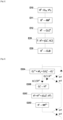
- Figure 1 represents the main steps of a method for determining an optimal configuration CLB according to a particular embodiment of the invention.
- This method is based on an exploration of the possible beam configurations b' of the LiDAR system LiD.
- configurations are selected, tested, and then added to a history. Recall that testing a configuration means obtaining actual performance associated with that configuration, and requires the execution of the specific task by the LiDAR system configured according to that configuration.
- the exploration step E20 has four main substeps E20A, E20B, E20C, and E20D shown in this Figure 2 .
- the exploration step is preceded by three steps E10, E11 and E12.
- a first step E10 of obtaining an initial history H 0 possible configurations of the LiDAR system LiD are randomly selected. For example, if the LiDAR system comprises k beams and if a configuration of these beams corresponds to the data of one position among K positions allowed for each of these beams, then each configuration CL n is selected at random among the possible K !/( k ! (K - k)!) possible configurations in this case.
- the configurations CL n and their associated actual performance VT n thus obtained form the initial history H 0 , which is used in the following steps E11 and E12, as well as at the beginning of the exploration step E20.
- the initial history H 0 obtained during step E10 is used to update an initial prediction function NN 0 .
- this initial prediction function is configured to calculate predicted performances of the configurations included in the initial history H 0 that are as close as possible to the actual performances associated with these configurations.
- this prediction function NN 0 is an artificial neural network. It should be noted that this example is not limiting and that the prediction function NN 0 may, in another embodiment of the invention, take the form of a standard machine learning model, for example a linear regression model or a random forest model.
- the update of this prediction function NN 0 from the history can be performed by a gradient descent algorithm [the man skilled in the art can consult the 2017 paper " An overview of gradient descent optimization algorithms" by Sebastian Ruder, arXiv:1609.04747v2, 2017 ] which allows to configure the prediction function NN 0 to minimize an error between the actual performances associated with the configurations included in the initial history H 0 and the predicted performances computed by this prediction function NN 0 .
- This error is for example the average of the squares of the differences between each predicted performance and each actual performance associated with each configuration included in the history.
- the initial prediction function NN 0 computes a predicted performance of a configuration from descriptive values of that configuration.
- the initial and new prediction functions will also, in the exploration step E20, use descriptive values of a configuration to calculate the predicted performance of that configuration.
- the descriptive values of this configuration can be determined and then stored, so that these descriptive values do not have to be determined again during a subsequent calculation of the predicted performance of this same configuration.
- the descriptive values of a configuration of the beams b i of a LiDAR system LiD comprise, for each beam b' of the LiDAR system LiD:
- a number of at least M scans by the LiDAR system are thus performed for each configuration whose predicted performance is calculated, where, as mentioned above, each scan corresponds to obtaining a point cloud corresponding to the positions in the space surrounding the LiDAR system at which the beams b i have reflected.
- a configuration of a LiDAR system LiD has values of angles that each of these beams form, and in order to not repeat the execution of M scans for each configuration of the LiDAR system LiD, a second LiDAR system with a larger number of beams can be used.
- a second 40-beam LiDAR system can be used to perform M scans.
- the different beams of this second LiDAR system form different angles with an axis of this system.
- selecting the points collected by 4 of the 40 beams is equivalent to obtaining a scan of the LiDAR system comprising only 4 beams configured according to these same angles. It is therefore possible, from a single scan of the second LiDAR system with 40 beams, to simulate the scans of the LiDAR system with 4 beams for all the configurations with 4 values of angles among 40 allowed, i.e. 91390 possible configurations.
- These scans are, for example, performed prior to the implementation of the method of determining an optimal beam configuration of the LiDAR system.
- these scans are also used in obtaining actual performance associated with configurations of a LiDAR system, as described below for particular embodiments of the invention.
- the initial history H 0 obtained in step E10 is used to obtain this first configuration which is used as the initial configuration CLC 0 at the beginning of the exploration step E20.
- the first selected configuration is the configuration CL n of the initial history H 0 with the best associated actual performance VT n .
- step E30 the optimal configuration CLB is selected from the new history H T formed during the T iterations I 1 -I T of the exploration step E20.
- This optimal configuration CLB is the configuration in the history with the best associated actual performance.
- Figure 2 represents the various substeps E20A, E20B, E20C, E20D of the aforementioned exploration step E20, in a particular embodiment of the invention.
- the exploration step E20 is performed in a fixed number T of iterations I 1 -I T , and thus allows to obtain at most T new configurations CL 1 -CL T and their associated actual performances VT 1 -VT T .
- the number T can be equal to 100.
- different stopping criteria may be used to terminate the exploration step. For example, following the addition, in the initial history, of a new configuration having an associated actual performance exceeding a predetermined threshold, the exploration step E20 is terminated.
- a new configuration CL t is selected from potential configurations CLP k t of the LiDAR system according to an exploration strategy.
- the potential configurations CLP k t are determined from the initial configuration CL t-1 obtained in the previous iteration if it exists or from the initial configuration CL 0 obtained in step E12 otherwise.
- these potential configurations CLP k t are obtained by applying potential actions AP k to the initial configuration CL 0 or CL t-1 . If a configuration corresponds to the values of the angles of each of the beams of the LiDAR system, these potential actions AP k may, for example, correspond to angle variations.
- angle variations of more or less two angle units an angle unit being the difference between two consecutive angles that can be formed by a beam of the LiDAR system LiD
- angle variations of more or less two angle units allowed to obtain configurations close enough to the initial configuration, and far enough away to obtain a fast exploration of the configuration space of the LiDAR system LiD.
- the exploration strategy indicating which new configuration CL t select from the potential configurations CLP k t favors selecting the configuration from the initial history H t-1 or H 0 whose initial prediction function NN t or NN 0 predicts the best predicted performance.
- the exploration strategy is a so-called " ⁇ -greedy" strategy.
- ⁇ -greedy a number is randomly drawn between 0 and 1, initially. If this number is less than a probability ⁇ , then the new configuration is randomly selected from the potential configurations. If this number is greater than probability ⁇ , then the new configuration selected is the potential configuration with the best performance predicted by the initial prediction function.
- ⁇ favors the exploitation of the prediction function NN t , i.e., favors all the more the selection of new configurations with better predicted performances. Conversely, increasing the value of ⁇ increases exploration, by allowing more new configurations to be selected at random.
- a typical value of ⁇ allowing a good trade-off between exploitation and exploration is 0.1.
- the value of ⁇ is determined as a function of the number of iterations I t of the exploration step having been performed. For example, ⁇ may decrease with the number of iterations. Thus, the more the initial prediction function has been updated, the more its exploitation is favored.
- the exploration strategy is a Bayesian optimization strategy [the man skilled in the art can consult " Bayesian Optimization", by Roman Garnett, Cambridge University Press, 2022 , also published on github: https://github.com/bayesoptbook/bayesoptbook.github.io].
- a prediction function of a predicted performance is determined from a probability distribution, for example Gaussian, of the actual performances associated with the possible configurations of the LiDAR system.
- This probability distribution makes it possible to calculate, from a given configuration, and from the knowledge of the configurations included in the initial history with their associated actual performances, probabilities of the possible values of the actual performance associated with this given configuration. These probabilities of these possible values allow to calculate an average and a standard deviation of the possible values of the actual performance associated to the given configuration.
- the predicted performance of a given configuration is the average of the possible values of the actual performance associated with this given configuration. Furthermore, a value proportional to the standard deviation of the possible values of the actual performance associated with this given configuration corresponds to an uncertainty on the predicted performance of this configuration.
- the exploration strategy indicates for example to select the new configuration whose predicted performance summed with the uncertainty on this predicted performance is the highest.
- substep E20B the actual performance VT t associated with the new configuration CL t , itself obtained in substep E20A, is obtained.
- the actual performance is obtained from scans of the LiDAR system LiD configured according to this new configuration. These scans are, for example, the same scans as those, described above, which allowed the determination of descriptive values of configurations of the LiDAR system LiD.
- substep E20C the new configuration CT t and its associated actual performance VT t , obtained in substeps E20A and E20B, are added to the initial history H t-1 , which then becomes the new history H t , which is used in the step E20D of updating the initial prediction function NN t and will constitute the initial history in the next iteration I t+1 of the exploration step, if it takes place.
- step E20D the initial prediction function NN t is updated from the new history H t obtained during substep E20C. This update is for example performed in the same way as step E11 of updating the initial prediction function NN 0 from the initial history H 0 .
- the new prediction function NN t+1 thus obtained will constitute the initial prediction function during the next iteration of the exploration step, if it takes place.
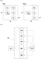
- Figure 3 represents the execution of two separate specific tasks to achieve actual performance associated with a beam configuration of the LiDAR system.
- Figure 3A represents the task of detecting objects in three dimensions while Figure 3B represents the task of locating objects on a map.
- a LiDAR system can be directly used for three-dimensional object detection. This means that object detection is performed from the point clouds harvested by the LiDAR system, without the additional use of a device other than the LiDAR system. In particular, this allows for accurate object detection if the LiDAR system has many beams, so that the point cloud it collects covers a large portion of the surrounding space.
- This point cloud is then analyzed by a three-dimensional object detection algorithm, for example the PointPillars algorithm [the man skilled in the art can consult the article " PointPillars: Fast Encoders for Object Detection from Point Clouds", by Alex H. Lang et al, arXiv:1812.05784v2, 2019 ].
- the point cloud that is analyzed by an object detection algorithm is not obtained by the LiDAR system alone, but is obtained in a pipeline 3Ddet.
- the point cloud is obtained from a stereo camera Cam and a LiDAR system LiD configured in a new configuration CL t of its beams.
- the obtaining of a point cloud is performed in several steps:
- Pseudo-LiDAR++ Accurate Depth for 3D Object Detection in Autonomous Driving", by You Yurong et al, arXiv:1906.06310v3, 2020 ]
- the point cloud generated from the corrected depth map is then analyzed by a three-dimensional object detection algorithm Det, such as PointPillars, to detect objects in the surrounding space represented by this point cloud.
- Det such as PointPillars
- a point cloud is obtained for each scan and capture performed by the LiDAR system and the stereo camera, respectively.
- Each obtained point cloud is analyzed by a three-dimensional object detection algorithm.
- a three-dimensional object detection algorithm generates three-dimensional Boxes Box corresponding to the positions occupied by the objects detected by this algorithm.
- these three-dimensional boxes Box generated by the algorithm are compared to three-dimensional boxes corresponding to the true positions of objects in three-dimensional space, for example determined by a human.
- This detection score is for example a mean average precision score.
- the actual performance VT t associated with the configuration CL t of the LiDAR system used in obtaining this detection score is equal to this detection score.
- Figure 3B shows a pipeline Maploc for executing an object localization task on a map MAP with a LiDAR system LiD configured according to a new configuration CL t .
- the LiDAR system LiD scans through the space represented by the map, and geographic position data from the LiDAR system (e.g., GNSS data) is obtained at each scan.
- geographic position data from the LiDAR system e.g., GNSS data
- the position of the LiDAR system LiD at each scan is projected onto the map from the geographic data.
- the LiDAR system LiD detects objects and their positions relative to the LiDAR system LiD during each scan.
- the positions Loc of these detected objects are located on the map, with an ICP algorithm [the man skilled in the art can consult the article " ICP-Based Pose-Graph SLAM", by Ellon Mendes et al, IEEE International Symposium on Safety, Security, and Rescue Robotics (SSRR), 2016, pp. 195-200 ].
- these positions Loc obtained from the LiDAR system LiD are for example compared to the true positions of objects on the map, for example determined by a human.
- the actual performance VT t associated with the configuration CL t is equal to such an accuracy score obtained from the LiDAR system LiD configured according to this configuration CL t .
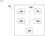
- Figure 4 depicts a determination device DD according to a particular embodiment of the invention for determining an optimal configuration CLB of a LiDAR system LiD.
- the device DD includes a module M10 for obtaining an initial history H 0 .
- This module randomly selects possible configurations of the LiDAR system and obtains the actual performances associated with the configurations thus selected, to constitute this initial history H 0 .
- the device DD includes a module M11 for the first update of an initial prediction function from the initial history H 0 obtained by the module M10.
- the device DD also includes a module M12 for selecting an initial configuration CL 0 as the configuration of the initial history H 0 for which the initial prediction function calculates the best predicted performance.
- the device DD includes a module M20 configured to implement an exploration step in accordance with the determination method described above. This exploration step implemented by the module M20 results in obtaining a new history H T .
- the module M30 of the device DD selects the optimal configuration CLB as the configuration obtained by the module M20, having the best associated actual performance among configurations included in the history.
- Figure 5 depicts the hardware architecture of a DD determination device according to a particular embodiment of the invention.
- the determination device DD has a hardware architecture of a computer.
- it comprises a processor DD1, a read-only memory DD2, a random access memory DD3, a rewritable non-volatile memory DD4 and communication means DD5.
- the read-only memory DD2 of the device DD constitutes a storage medium in accordance with the invention, readable by the processor DD1 and on which is stored a computer program PGI in accordance with the invention, this program comprising instructions for executing the steps of a determination method in accordance with the invention described previously with reference to Figure 1 in an embodiment.
- the computer program PGI defines functional modules of the determination device DD shown in Figure 4 .
Landscapes
- Physics & Mathematics (AREA)
- Engineering & Computer Science (AREA)
- Electromagnetism (AREA)
- General Physics & Mathematics (AREA)
- Remote Sensing (AREA)
- Radar, Positioning & Navigation (AREA)
- Computer Networks & Wireless Communication (AREA)
- Theoretical Computer Science (AREA)
- General Health & Medical Sciences (AREA)
- Mathematical Physics (AREA)
- Data Mining & Analysis (AREA)
- Molecular Biology (AREA)
- Computing Systems (AREA)
- General Engineering & Computer Science (AREA)
- Computational Linguistics (AREA)
- Evolutionary Computation (AREA)
- Software Systems (AREA)
- Biophysics (AREA)
- Biomedical Technology (AREA)
- Artificial Intelligence (AREA)
- Life Sciences & Earth Sciences (AREA)
- Health & Medical Sciences (AREA)
- Optical Radar Systems And Details Thereof (AREA)
Claims (19)
- Verfahren zum Bestimmen einer optimalen Konfiguration (CLB) der Strahlen (bi) eines LiDAR-Systems (LiD), das dazu bestimmt ist, eine bestimmte Aufgabe durchzuführen, wobei in dem Verfahren:- eine tatsächliche Leistung, die mit einer Konfiguration der Strahlen verbunden ist, einer Qualität des Resultats einer Ausführung der spezifischen Aufgabe durch das LiDAR-System (LiD) entspricht, das gemäß dieser Konfiguration konfiguriert ist;- eine vorhergesagte Leistung einer Konfiguration eine Vorhersage einer tatsächlichen Leistung ist, die mit dieser Konfiguration assoziiert ist;das Verfahren umfassend:(i) einen Erkundungsschritt (E20), umfassend mindestens eine Iteration (It) der folgenden Teilschritte:(a) Auswählen (E20A) einer neuen Konfiguration aus mindestens einer potenziellen Konfiguration (CLPk t) des LiDAR-Systems (LiD), wobei ein Auswählen gemäß einer Erkundungsstrategie durchgeführt wird, für die eine Konfiguration, deren vorhergesagte Leistung (VPt) die beste von der mindestens einen potenziellen Konfiguration ist, eine höhere Chance hat, ausgewählt zu werden, wobei die vorhergesagte Leistung einer Konfiguration durch eine anfängliche Vorhersagefunktion zugewiesen wird, wobei die anfängliche Vorhersagefunktion ein Modell für maschinelles Lernen ist;(b) Erlangen (E20B) einer tatsächlichen Leistung (VTt) assoziiert mit der neuen Konfiguration (CLt);(c) Erlangen (E20C) einer neuen Historie (Ht) durch Hinzufügen der neuen Konfiguration (CLt) und ihrer tatsächlichen Leistung (VTt), die mit einer anfänglichen Historie (Ht-1) assoziiert ist;(d) Erlangen (E20D) einer neuen Vorhersagefunktion (NNt+1) durch Modifizieren der anfänglichen Vorhersagefunktion (NNt) auf eine Weise, dass sie mindestens einer Konfiguration (CLn), die in der neuen Historie (Ht) beinhaltet ist, mindestens eine vorhergesagte Leistung (VPn t) zuweist, die der assoziierten mindestens einen tatsächlichen Leistung (VTn) so nahe wie möglich ist;wobei die neue Historie (Ht) und die neue Vorhersagefunktion (NNt+1) jeweils die anfängliche Historie (Ht-1) und die anfängliche Vorhersagefunktion (Nt) für eine nächste Iteration des Erkundungsschritts (E20) darstellen, bis ein Abbruchkriterium des Erkundungsschritts (E20) erfüllt ist;(ii) Bestimmen (E30) der optimalen Konfiguration (CLB) als die Konfiguration (CLn), die die beste assoziierte tatsächliche Leistung (VTn) von der neuen Historie (Ht) aufweist.
- Verfahren nach Anspruch 1, wobei das Abbruchkriterium ein Erreichen einer vorbestimmten Anzahl (T) der Iterationen (It) des Erkundungsschritts (E20) ist.
- Verfahren nach Anspruch 1, wobei das Abbruchkriterium das Vorhandensein einer tatsächlichen Leistung (VTt) in der neuen Historie (Ht) ist, die einen Schwellenwert überschreitet.
- Verfahren nach einem der Ansprüche 1 bis 3, wobei die Vorhersagefunktion (NNt) ein künstliches neuronales Netz ist.
- Verfahren nach einem der Ansprüche 1 bis 4, wobei:- die mindestens eine potentielle Konfiguration (CLPk t) durch Anwenden mindestens einer potentiellen Aktion (APk) auf eine anfängliche Konfiguration (CLt-1), die in der anfänglichen Historie beinhaltet ist, bestimmt wird, und- die neue Konfiguration (CLt) die anfängliche Konfiguration (CLt-1) für eine nachfolgende Iteration des Erkundungsschritts (E20) darstellt.
- Verfahren nach Anspruch 5, wobei- die anfängliche Historie (H0) mindestens eine Konfiguration (CLn) des LiDAR-Systems (LiD) und die damit verbundene tatsächliche Leistung (VTn) umfasst,und umfassend- einen Schritt (E12), der vor dem Erkundungsschritt (E20) durchgeführt wird, eines Auswählens einer ersten Konfiguration (CLO) als die Konfiguration (CLn) der anfänglichen Historie (H0), die die beste assoziierte tatsächliche Leistung (VTn) aufweist, wobei die erste Konfiguration (CLO) die anfängliche Konfiguration (CLC0) während einer ersten Iteration des Erkundungsschritts (E20) darstellt.
- Verfahren nach einem der Ansprüche 1 bis 6, wobei:- ein Wahrscheinlichkeitswert ε gemäß einer Anzahl der durchgeführten Iterationen (It) des Erkundungsschritts (E20) festgelegt oder berechnet wird;- wobei die Erkundungsstrategie angibt, Folgendes auszuwählen(i) mit einer Wahrscheinlichkeit gleich ε die neue Konfiguration (CLt) zufällig aus der mindestens einen möglichen Konfiguration (CLPk t), oder(ii) mit einer Wahrscheinlichkeit gleich 1-ε die neue Konfiguration (CLt) aus den möglichen Konfigurationen (CLPk t), der die anfängliche Vorhersagefunktion (NNt) die beste vorhergesagte Leistung (VPt) zuweist.
- Verfahren nach einem der Ansprüche 1 bis 7, wobei die Zuordnung einer vorhergesagten Leistung (VPn t) zu einer Konfiguration (CLn) des LiDAR-Systems (LiD) durch eine Vorhersagefunktion (NNt) die folgenden Schritte umfasst:- Erlangen von Beschreibungswerten (Fn) für die Konfiguration (CLn);- Berechnen, durch die anfängliche Vorhersagefunktion (NNt), der vorhergesagten Leistung (VPn t) der Konfiguration (CLn) aus diesen Beschreibungswerten (Fn).
- Verfahren nach Anspruch 8, wobei die Beschreibungswerte (Fn) der Konfiguration (CLn) für mindestens einen der Strahlen (bi) des gemäß der Konfiguration (CLn) konfigurierten LiDAR-Systems (LiD) mindestens einen Wert von Folgenden umfassen:- einen Durchschnitt einer Anzahl von Punkten, die während einer festgelegten Anzahl (M) von Abtastungen durch den mindestens einen Strahl (bi) erlangt werden;- einen Durchschnitt einer Anzahl von Punkten einer gegebenen semantischen Klasse, die während der festgelegten Anzahl (M) von Abtastungen durch den mindestens einen Strahl (bi) erlangt werden;- einen Durchschnitt von Abständen zwischen dem LiDAR-System (LiD) und den Punkten, die während der festgelegten Anzahl (M) von Abtastungen durch den mindestens einen Strahl (bi) erlangt werden;- eine Streuung von Abständen zwischen dem LiDAR-System (LiD) und den Punkten, die während der festgelegten Anzahl (M) von Abtastungen durch den mindestens einen Strahl (bi) erlangt werden;- einen Durchschnitt von Winkeln zwischen einer Achse des LiDAR-Systems (LiD) und den Punkten, die während der festgelegten Anzahl (M) von Abtastungen durch den mindestens einen Strahl (bi) erlangt werden;- eine Differenz zwischen dem Durchschnitt von Winkeln, der für den Strahl (bi) erlangt wird, und einen Durchschnitt von Winkeln, der für einen anderen Strahl (bi) erlangt wird.
- Verfahren nach einem der Ansprüche 1 bis 9, umfassend einen Schritt (E10), der vor dem Erkundungsschritt (E20) durchgeführt wird, eines Erlangens der anfänglichen Historie (H0) durch zufälliges Auswählen mindestens einer Konfiguration des LiDAR-Systems (LiD) und eines Erlangens der mindestens einen tatsächlichen Leistung, die mit dieser mindestens einen Konfiguration assoziiert ist.
- Verfahren nach einem der Ansprüche 1 bis 10, wobei- die anfängliche Historie (H0) mindestens eine Konfiguration (CLn) des LiDAR-Systems (LiD) und ihre damit assoziierte tatsächliche Leistung (VTn) beinhaltet,und umfassend- einen Schritt (E11), der vor dem Erkundungsschritt (E20) durchgeführt wird, eines ersten Aktualisierens der anfänglichen Vorhersagefunktion (NN0) von der anfänglichen Historie (H0).
- Verfahren nach einem der Ansprüche 1 bis 11, wobei auf den Teilschritt a eines Auswählens (E20A) der neuen Konfiguration (CLt) Folgendes folgt:- das Ende der aktuellen Iteration (It) des Erkundungsschritts (E20), wenn und nur wenn die neue Konfiguration (CLt) in der anfängliche Historie (Ht-1) beinhaltet ist,- das Ende des Erkundungsschritts (E20), wenn das Abbruchkriterium erfüllt ist, oder- sonst die nächste Iteration (It-1) des Erkundungsschritts (E20).
- Verfahren nach einem der Ansprüche 1 bis 12, wobei:- die spezifische Aufgabe eine Erfassung von Objekten in drei Dimensionen ist, und- ein Erlangen einer tatsächlichen Leistung (VTn), die mit der Konfiguration (CLn) assoziiert ist, die folgenden Schritte umfasst:(i) Erfassen von Objekten in drei Dimensionen mit dem LiDAR-System (LiD), das gemäß der Konfiguration (CLn) konfiguriert ist;(iii) Berechnen eines Erfassungsresultats aus einem Resultat des Erfassungsschritts i;(iv) Berechnen der tatsächlichen Leistung (VTn) abhängig von der Erfassungsrate.
- Verfahren nach einem der Ansprüche 1 bis 12, wobei- die spezifische Aufgabe eine Lokalisierung von Objekten auf einer Karte ist, und- ein Erlangen einer tatsächlichen Leistung (VTn), die mit der Konfiguration (CLn) assoziiert ist, die folgenden Schritte umfasst:(i) Lokalisieren von Objekten auf einer Karte mit dem LiDAR-System (LiD), das gemäß der Konfiguration (CLn) konfiguriert ist;(ii) Berechnen einer Lokalisierungsrate aus einem Resultat des Lokalisierungsschritts i;(iii) Berechnen der tatsächlichen Leistung (VTn) abhängig von der Lokalisierungsrate.
- Verfahren nach einem der Ansprüche 1 bis 14, wobei die Ausführung der spezifischen Aufgabe durch das LiDAR-System (LiD) computersimuliert wird.
- Verfahren nach einem der Ansprüche 1 bis 15, umfassend einen Schritt eines Konfigurierens eines LiDAR-Systems (LiD) gemäß der optimalen Konfiguration (CLB).
- Vorrichtung (DD) zum Bestimmen einer optimalen Konfiguration (CLB) der Strahlen (bi) eines LiDAR-Systems (LiD), das dazu bestimmt ist, eine bestimmte Aufgabe durchzuführen, wobei für die Vorrichtung:- eine tatsächliche Leistung, die mit einer Konfiguration der Strahlen verbunden ist, einer Qualität des Resultats einer Ausführung der spezifischen Aufgabe durch das LiDAR-System (LiD) entspricht, das gemäß dieser Konfiguration konfiguriert ist;- eine vorhergesagte Leistung einer Konfiguration eine Vorhersage einer tatsächlichen Leistung ist, die mit dieser Konfiguration assoziiert ist;die Vorrichtung umfassend:(i) ein Modul (M20), das konfiguriert ist, um einen Erkundungsschritt zu implementieren, umfassend mindestens eine Iteration (It) der folgenden Teilschritte:(a) Auswählen (E20A) einer neuen Konfiguration aus mindestens einer potenziellen Konfiguration (CLPk t) des LiDAR-Systems (LiD), wobei ein Auswählen gemäß einer Erkundungsstrategie durchgeführt wird, für die eine Konfiguration, deren vorhergesagte Leistung (VPt) die beste von der mindestens einen potenziellen Konfiguration ist, eine höhere Chance hat, ausgewählt zu werden, wobei die vorhergesagte Leistung einer Konfiguration durch eine anfängliche Vorhersagefunktion zugewiesen wird, wobei die anfängliche Vorhersagefunktion ein Modell für maschinelles Lernen ist;(b) Erlangen (E20B) einer tatsächlichen Leistung (VTt) assoziiert mit der neuen Konfiguration (CLt);(c) Erlangen (E20C) einer neuen Historie (Ht) durch Hinzufügen der neuen Konfiguration (CLt) und ihrer tatsächlichen Leistung (VTt), die mit einer anfänglichen Historie (Ht-1) assoziiert ist;(d) Erlangen (E20D) einer neuen Vorhersagefunktion (NNt+1) durch Modifizieren der anfänglichen Vorhersagefunktion (NNt) auf eine Weise, dass sie mindestens einer Konfiguration (CLn), die in der neuen Historie (Ht) beinhaltet ist, mindestens eine vorhergesagte Leistung (VPn t) zuweist, die der assoziierten mindestens einen tatsächlichen Leistung (VTn) so nahe wie möglich ist;wobei die neue Historie (Ht) und die neue Vorhersagefunktion (NNt+1) jeweils die anfängliche Historie (Ht-1) und die anfängliche Vorhersagefunktion (Nt) für eine nächste Iteration des Erkundungsschritts (E20) darstellen, bis ein Abbruchkriterium des Erkundungsschritts (E20) erfüllt ist;(iii) ein Modul zum Bestimmen (E30) der optimalen Konfiguration (CLB) als die Konfiguration (CLn), die die beste assoziierte tatsächliche Leistung (VTn) von der neuen Historie (Ht) aufweist.
- Computerprogramm (PGI), umfassend Anweisungen zum Durchführen aller Schritte des Verfahrens nach mindestens einem der Ansprüche 1-16, wenn es auf einem Computer ausgeführt wird.
- Speichermedium (DD2), das von einer Computerausrüstung (EI) eines Computerprogramms (PGI) lesbar ist, umfassend Anweisungen zum Ausführen aller Schritte des Verfahrens nach mindestens einem der Ansprüche 1 bis 16 durch die Computerausrüstung.
Priority Applications (1)
| Application Number | Priority Date | Filing Date | Title |
|---|---|---|---|
| EP21216059.2A EP4198567B1 (de) | 2021-12-20 | 2021-12-20 | Verfahren zur bestimmung der strahlkonfiguration eines lidar-systems |
Applications Claiming Priority (1)
| Application Number | Priority Date | Filing Date | Title |
|---|---|---|---|
| EP21216059.2A EP4198567B1 (de) | 2021-12-20 | 2021-12-20 | Verfahren zur bestimmung der strahlkonfiguration eines lidar-systems |
Publications (2)
| Publication Number | Publication Date |
|---|---|
| EP4198567A1 EP4198567A1 (de) | 2023-06-21 |
| EP4198567B1 true EP4198567B1 (de) | 2025-01-08 |
Family
ID=79230550
Family Applications (1)
| Application Number | Title | Priority Date | Filing Date |
|---|---|---|---|
| EP21216059.2A Active EP4198567B1 (de) | 2021-12-20 | 2021-12-20 | Verfahren zur bestimmung der strahlkonfiguration eines lidar-systems |
Country Status (1)
| Country | Link |
|---|---|
| EP (1) | EP4198567B1 (de) |
Family Cites Families (1)
| Publication number | Priority date | Publication date | Assignee | Title |
|---|---|---|---|---|
| US10338225B2 (en) * | 2015-12-15 | 2019-07-02 | Uber Technologies, Inc. | Dynamic LIDAR sensor controller |
-
2021
- 2021-12-20 EP EP21216059.2A patent/EP4198567B1/de active Active
Also Published As
| Publication number | Publication date |
|---|---|
| EP4198567A1 (de) | 2023-06-21 |
Similar Documents
| Publication | Publication Date | Title |
|---|---|---|
| US20200233061A1 (en) | Method and system for creating an inverse sensor model and method for detecting obstacles | |
| US11531899B2 (en) | Method for estimating a global uncertainty of a neural network | |
| CN109932713B (zh) | 定位方法、装置、计算机设备、可读存储介质和机器人 | |
| EP1733287B1 (de) | System und verfahren zur adaptiven wegplanung | |
| CN110546459B (zh) | 具有数据融合的机器人跟踪导航 | |
| CN108983213B (zh) | 障碍物静止状态的确定方法、装置、设备及存储介质 | |
| US20170157769A1 (en) | Simultaneous mapping and planning by a robot | |
| JP6773471B2 (ja) | 自律移動体と環境地図更新装置 | |
| CN112668602A (zh) | 用于确定传感器的数据集的品质等级的方法、设备和机器可读的存储介质 | |
| US20200156241A1 (en) | Automation safety and performance robustness through uncertainty driven learning and control | |
| US12246450B2 (en) | Device and method to improve learning of a policy for robots | |
| EP3904973A1 (de) | Vorrichtung und verfahren zur steuerung eines roboters | |
| CN113219506A (zh) | 一种多模融合无缝切换的定位方法 | |
| KR20180092960A (ko) | 고속 탐색 랜덤화 피드백 기반의 모션 계획 | |
| CN111971628A (zh) | 求得被测变量的时间曲线的方法、预测系统、致动器控制系统、训练致动器控制系统的方法、训练系统、计算机程序和机器可读的存储介质 | |
| US20200401151A1 (en) | Device motion control | |
| Choi et al. | Hybrid map-based SLAM with Rao-Blackwellized particle filters | |
| EP4198567B1 (de) | Verfahren zur bestimmung der strahlkonfiguration eines lidar-systems | |
| Asraf et al. | Experience-based prediction of unknown environments for enhanced belief space planning | |
| KR20240172495A (ko) | 객체의 현재 상태를 추정하는 상태 추정 장치 및 방법 | |
| CN111546348A (zh) | 机器人位置标定方法和位置标定系统 | |
| CN119693907B (zh) | 基于视觉的车辆转向状态判别方法及系统 | |
| CN119622317B (zh) | 机器人环境感知数据处理方法、系统、设备及介质 | |
| JP6438354B2 (ja) | 自己位置推定装置及び自己位置推定装置を備えた移動体 | |
| Sabatini et al. | Improving occupancy grid mapping via dithering for a mobile robot equipped with solid-state lidar sensors |
Legal Events
| Date | Code | Title | Description |
|---|---|---|---|
| PUAI | Public reference made under article 153(3) epc to a published international application that has entered the european phase |
Free format text: ORIGINAL CODE: 0009012 |
|
| STAA | Information on the status of an ep patent application or granted ep patent |
Free format text: STATUS: REQUEST FOR EXAMINATION WAS MADE |
|
| 17P | Request for examination filed |
Effective date: 20211220 |
|
| AK | Designated contracting states |
Kind code of ref document: A1 Designated state(s): AL AT BE BG CH CY CZ DE DK EE ES FI FR GB GR HR HU IE IS IT LI LT LU LV MC MK MT NL NO PL PT RO RS SE SI SK SM TR |
|
| GRAP | Despatch of communication of intention to grant a patent |
Free format text: ORIGINAL CODE: EPIDOSNIGR1 |
|
| STAA | Information on the status of an ep patent application or granted ep patent |
Free format text: STATUS: GRANT OF PATENT IS INTENDED |
|
| RIC1 | Information provided on ipc code assigned before grant |
Ipc: G01S 7/497 20060101ALN20240912BHEP Ipc: G06N 3/084 20230101ALI20240912BHEP Ipc: G01S 17/42 20060101ALI20240912BHEP Ipc: G06N 7/00 20230101ALI20240912BHEP Ipc: G06N 5/00 20230101ALI20240912BHEP Ipc: G06N 3/08 20230101ALI20240912BHEP Ipc: G01S 17/89 20200101ALI20240912BHEP Ipc: G01S 17/04 20200101ALI20240912BHEP Ipc: G01S 17/00 20200101AFI20240912BHEP |
|
| INTG | Intention to grant announced |
Effective date: 20241010 |
|
| GRAS | Grant fee paid |
Free format text: ORIGINAL CODE: EPIDOSNIGR3 |
|
| GRAA | (expected) grant |
Free format text: ORIGINAL CODE: 0009210 |
|
| STAA | Information on the status of an ep patent application or granted ep patent |
Free format text: STATUS: THE PATENT HAS BEEN GRANTED |
|
| AK | Designated contracting states |
Kind code of ref document: B1 Designated state(s): AL AT BE BG CH CY CZ DE DK EE ES FI FR GB GR HR HU IE IS IT LI LT LU LV MC MK MT NL NO PL PT RO RS SE SI SK SM TR |
|
| REG | Reference to a national code |
Ref country code: GB Ref legal event code: FG4D |
|
| REG | Reference to a national code |
Ref country code: CH Ref legal event code: EP |
|
| REG | Reference to a national code |
Ref country code: DE Ref legal event code: R096 Ref document number: 602021024624 Country of ref document: DE |
|
| REG | Reference to a national code |
Ref country code: IE Ref legal event code: FG4D |
|
| REG | Reference to a national code |
Ref country code: LT Ref legal event code: MG9D |
|
| REG | Reference to a national code |
Ref country code: NL Ref legal event code: MP Effective date: 20250108 |
|
| REG | Reference to a national code |
Ref country code: AT Ref legal event code: MK05 Ref document number: 1758672 Country of ref document: AT Kind code of ref document: T Effective date: 20250108 |
|
| PG25 | Lapsed in a contracting state [announced via postgrant information from national office to epo] |
Ref country code: NL Free format text: LAPSE BECAUSE OF FAILURE TO SUBMIT A TRANSLATION OF THE DESCRIPTION OR TO PAY THE FEE WITHIN THE PRESCRIBED TIME-LIMIT Effective date: 20250108 |
|
| PG25 | Lapsed in a contracting state [announced via postgrant information from national office to epo] |
Ref country code: RS Free format text: LAPSE BECAUSE OF FAILURE TO SUBMIT A TRANSLATION OF THE DESCRIPTION OR TO PAY THE FEE WITHIN THE PRESCRIBED TIME-LIMIT Effective date: 20250408 |
|
| PG25 | Lapsed in a contracting state [announced via postgrant information from national office to epo] |
Ref country code: FI Free format text: LAPSE BECAUSE OF FAILURE TO SUBMIT A TRANSLATION OF THE DESCRIPTION OR TO PAY THE FEE WITHIN THE PRESCRIBED TIME-LIMIT Effective date: 20250108 |
|
| PG25 | Lapsed in a contracting state [announced via postgrant information from national office to epo] |
Ref country code: PL Free format text: LAPSE BECAUSE OF FAILURE TO SUBMIT A TRANSLATION OF THE DESCRIPTION OR TO PAY THE FEE WITHIN THE PRESCRIBED TIME-LIMIT Effective date: 20250108 |
|
| PG25 | Lapsed in a contracting state [announced via postgrant information from national office to epo] |
Ref country code: ES Free format text: LAPSE BECAUSE OF FAILURE TO SUBMIT A TRANSLATION OF THE DESCRIPTION OR TO PAY THE FEE WITHIN THE PRESCRIBED TIME-LIMIT Effective date: 20250108 |
|
| PG25 | Lapsed in a contracting state [announced via postgrant information from national office to epo] |
Ref country code: NO Free format text: LAPSE BECAUSE OF FAILURE TO SUBMIT A TRANSLATION OF THE DESCRIPTION OR TO PAY THE FEE WITHIN THE PRESCRIBED TIME-LIMIT Effective date: 20250408 Ref country code: IS Free format text: LAPSE BECAUSE OF FAILURE TO SUBMIT A TRANSLATION OF THE DESCRIPTION OR TO PAY THE FEE WITHIN THE PRESCRIBED TIME-LIMIT Effective date: 20250508 |
|
| PG25 | Lapsed in a contracting state [announced via postgrant information from national office to epo] |
Ref country code: HR Free format text: LAPSE BECAUSE OF FAILURE TO SUBMIT A TRANSLATION OF THE DESCRIPTION OR TO PAY THE FEE WITHIN THE PRESCRIBED TIME-LIMIT Effective date: 20250108 |
|
| PG25 | Lapsed in a contracting state [announced via postgrant information from national office to epo] |
Ref country code: PT Free format text: LAPSE BECAUSE OF FAILURE TO SUBMIT A TRANSLATION OF THE DESCRIPTION OR TO PAY THE FEE WITHIN THE PRESCRIBED TIME-LIMIT Effective date: 20250508 Ref country code: LV Free format text: LAPSE BECAUSE OF FAILURE TO SUBMIT A TRANSLATION OF THE DESCRIPTION OR TO PAY THE FEE WITHIN THE PRESCRIBED TIME-LIMIT Effective date: 20250108 |
|
| PG25 | Lapsed in a contracting state [announced via postgrant information from national office to epo] |
Ref country code: GR Free format text: LAPSE BECAUSE OF FAILURE TO SUBMIT A TRANSLATION OF THE DESCRIPTION OR TO PAY THE FEE WITHIN THE PRESCRIBED TIME-LIMIT Effective date: 20250409 Ref country code: BG Free format text: LAPSE BECAUSE OF FAILURE TO SUBMIT A TRANSLATION OF THE DESCRIPTION OR TO PAY THE FEE WITHIN THE PRESCRIBED TIME-LIMIT Effective date: 20250108 |
|
| PG25 | Lapsed in a contracting state [announced via postgrant information from national office to epo] |
Ref country code: AT Free format text: LAPSE BECAUSE OF FAILURE TO SUBMIT A TRANSLATION OF THE DESCRIPTION OR TO PAY THE FEE WITHIN THE PRESCRIBED TIME-LIMIT Effective date: 20250108 |
|
| PG25 | Lapsed in a contracting state [announced via postgrant information from national office to epo] |
Ref country code: SE Free format text: LAPSE BECAUSE OF FAILURE TO SUBMIT A TRANSLATION OF THE DESCRIPTION OR TO PAY THE FEE WITHIN THE PRESCRIBED TIME-LIMIT Effective date: 20250108 |
|
| PG25 | Lapsed in a contracting state [announced via postgrant information from national office to epo] |
Ref country code: SM Free format text: LAPSE BECAUSE OF FAILURE TO SUBMIT A TRANSLATION OF THE DESCRIPTION OR TO PAY THE FEE WITHIN THE PRESCRIBED TIME-LIMIT Effective date: 20250108 |
|
| REG | Reference to a national code |
Ref country code: DE Ref legal event code: R097 Ref document number: 602021024624 Country of ref document: DE |
|
| PG25 | Lapsed in a contracting state [announced via postgrant information from national office to epo] |
Ref country code: DK Free format text: LAPSE BECAUSE OF FAILURE TO SUBMIT A TRANSLATION OF THE DESCRIPTION OR TO PAY THE FEE WITHIN THE PRESCRIBED TIME-LIMIT Effective date: 20250108 |
|
| PG25 | Lapsed in a contracting state [announced via postgrant information from national office to epo] |
Ref country code: EE Free format text: LAPSE BECAUSE OF FAILURE TO SUBMIT A TRANSLATION OF THE DESCRIPTION OR TO PAY THE FEE WITHIN THE PRESCRIBED TIME-LIMIT Effective date: 20250108 Ref country code: CZ Free format text: LAPSE BECAUSE OF FAILURE TO SUBMIT A TRANSLATION OF THE DESCRIPTION OR TO PAY THE FEE WITHIN THE PRESCRIBED TIME-LIMIT Effective date: 20250108 |
|
| PG25 | Lapsed in a contracting state [announced via postgrant information from national office to epo] |
Ref country code: RO Free format text: LAPSE BECAUSE OF FAILURE TO SUBMIT A TRANSLATION OF THE DESCRIPTION OR TO PAY THE FEE WITHIN THE PRESCRIBED TIME-LIMIT Effective date: 20250108 |
|
| PG25 | Lapsed in a contracting state [announced via postgrant information from national office to epo] |
Ref country code: SK Free format text: LAPSE BECAUSE OF FAILURE TO SUBMIT A TRANSLATION OF THE DESCRIPTION OR TO PAY THE FEE WITHIN THE PRESCRIBED TIME-LIMIT Effective date: 20250108 |
|
| PLBE | No opposition filed within time limit |
Free format text: ORIGINAL CODE: 0009261 |
|
| STAA | Information on the status of an ep patent application or granted ep patent |
Free format text: STATUS: NO OPPOSITION FILED WITHIN TIME LIMIT |
|
| 26N | No opposition filed |
Effective date: 20251009 |
|
| PGFP | Annual fee paid to national office [announced via postgrant information from national office to epo] |
Ref country code: DE Payment date: 20251028 Year of fee payment: 5 |