EP4198459A1 - Dispositif de mesure de position pour unité de stator de machine électrique tournante - Google Patents
Dispositif de mesure de position pour unité de stator de machine électrique tournante Download PDFInfo
- Publication number
- EP4198459A1 EP4198459A1 EP22206421.4A EP22206421A EP4198459A1 EP 4198459 A1 EP4198459 A1 EP 4198459A1 EP 22206421 A EP22206421 A EP 22206421A EP 4198459 A1 EP4198459 A1 EP 4198459A1
- Authority
- EP
- European Patent Office
- Prior art keywords
- measuring device
- position measuring
- notch
- stator unit
- angle
- Prior art date
- Legal status (The legal status is an assumption and is not a legal conclusion. Google has not performed a legal analysis and makes no representation as to the accuracy of the status listed.)
- Granted
Links
Images

Classifications
-
- H—ELECTRICITY
- H02—GENERATION; CONVERSION OR DISTRIBUTION OF ELECTRIC POWER
- H02K—DYNAMO-ELECTRIC MACHINES
- H02K11/00—Structural association of dynamo-electric machines with electric components or with devices for shielding, monitoring or protection
- H02K11/20—Structural association of dynamo-electric machines with electric components or with devices for shielding, monitoring or protection for measuring, monitoring, testing, protecting or switching
- H02K11/21—Devices for sensing speed or position, or actuated thereby
-
- G—PHYSICS
- G01—MEASURING; TESTING
- G01D—MEASURING NOT SPECIALLY ADAPTED FOR A SPECIFIC VARIABLE; ARRANGEMENTS FOR MEASURING TWO OR MORE VARIABLES NOT COVERED IN A SINGLE OTHER SUBCLASS; TARIFF METERING APPARATUS; MEASURING OR TESTING NOT OTHERWISE PROVIDED FOR
- G01D5/00—Mechanical means for transferring the output of a sensing member; Means for converting the output of a sensing member to another variable where the form or nature of the sensing member does not constrain the means for converting; Transducers not specially adapted for a specific variable
- G01D5/12—Mechanical means for transferring the output of a sensing member; Means for converting the output of a sensing member to another variable where the form or nature of the sensing member does not constrain the means for converting; Transducers not specially adapted for a specific variable using electric or magnetic means
- G01D5/244—Mechanical means for transferring the output of a sensing member; Means for converting the output of a sensing member to another variable where the form or nature of the sensing member does not constrain the means for converting; Transducers not specially adapted for a specific variable using electric or magnetic means influencing characteristics of pulses or pulse trains; generating pulses or pulse trains
- G01D5/24428—Error prevention
- G01D5/24433—Error prevention by mechanical means
- G01D5/24442—Error prevention by mechanical means by mounting means
-
- G—PHYSICS
- G01—MEASURING; TESTING
- G01B—MEASURING LENGTH, THICKNESS OR SIMILAR LINEAR DIMENSIONS; MEASURING ANGLES; MEASURING AREAS; MEASURING IRREGULARITIES OF SURFACES OR CONTOURS
- G01B7/00—Measuring arrangements characterised by the use of electric or magnetic techniques
- G01B7/30—Measuring arrangements characterised by the use of electric or magnetic techniques for measuring angles or tapers; for testing the alignment of axes
-
- G—PHYSICS
- G01—MEASURING; TESTING
- G01D—MEASURING NOT SPECIALLY ADAPTED FOR A SPECIFIC VARIABLE; ARRANGEMENTS FOR MEASURING TWO OR MORE VARIABLES NOT COVERED IN A SINGLE OTHER SUBCLASS; TARIFF METERING APPARATUS; MEASURING OR TESTING NOT OTHERWISE PROVIDED FOR
- G01D11/00—Component parts of measuring arrangements not specially adapted for a specific variable
- G01D11/30—Supports specially adapted for an instrument; Supports specially adapted for a set of instruments
-
- G—PHYSICS
- G01—MEASURING; TESTING
- G01D—MEASURING NOT SPECIALLY ADAPTED FOR A SPECIFIC VARIABLE; ARRANGEMENTS FOR MEASURING TWO OR MORE VARIABLES NOT COVERED IN A SINGLE OTHER SUBCLASS; TARIFF METERING APPARATUS; MEASURING OR TESTING NOT OTHERWISE PROVIDED FOR
- G01D18/00—Testing or calibrating apparatus or arrangements provided for in groups G01D1/00 - G01D15/00
-
- G—PHYSICS
- G01—MEASURING; TESTING
- G01D—MEASURING NOT SPECIALLY ADAPTED FOR A SPECIFIC VARIABLE; ARRANGEMENTS FOR MEASURING TWO OR MORE VARIABLES NOT COVERED IN A SINGLE OTHER SUBCLASS; TARIFF METERING APPARATUS; MEASURING OR TESTING NOT OTHERWISE PROVIDED FOR
- G01D18/00—Testing or calibrating apparatus or arrangements provided for in groups G01D1/00 - G01D15/00
- G01D18/001—Calibrating encoders
-
- G—PHYSICS
- G01—MEASURING; TESTING
- G01D—MEASURING NOT SPECIALLY ADAPTED FOR A SPECIFIC VARIABLE; ARRANGEMENTS FOR MEASURING TWO OR MORE VARIABLES NOT COVERED IN A SINGLE OTHER SUBCLASS; TARIFF METERING APPARATUS; MEASURING OR TESTING NOT OTHERWISE PROVIDED FOR
- G01D5/00—Mechanical means for transferring the output of a sensing member; Means for converting the output of a sensing member to another variable where the form or nature of the sensing member does not constrain the means for converting; Transducers not specially adapted for a specific variable
- G01D5/12—Mechanical means for transferring the output of a sensing member; Means for converting the output of a sensing member to another variable where the form or nature of the sensing member does not constrain the means for converting; Transducers not specially adapted for a specific variable using electric or magnetic means
- G01D5/14—Mechanical means for transferring the output of a sensing member; Means for converting the output of a sensing member to another variable where the form or nature of the sensing member does not constrain the means for converting; Transducers not specially adapted for a specific variable using electric or magnetic means influencing the magnitude of a current or voltage
- G01D5/142—Mechanical means for transferring the output of a sensing member; Means for converting the output of a sensing member to another variable where the form or nature of the sensing member does not constrain the means for converting; Transducers not specially adapted for a specific variable using electric or magnetic means influencing the magnitude of a current or voltage using Hall-effect devices
- G01D5/145—Mechanical means for transferring the output of a sensing member; Means for converting the output of a sensing member to another variable where the form or nature of the sensing member does not constrain the means for converting; Transducers not specially adapted for a specific variable using electric or magnetic means influencing the magnitude of a current or voltage using Hall-effect devices influenced by the relative movement between the Hall device and magnetic fields
-
- H—ELECTRICITY
- H02—GENERATION; CONVERSION OR DISTRIBUTION OF ELECTRIC POWER
- H02K—DYNAMO-ELECTRIC MACHINES
- H02K11/00—Structural association of dynamo-electric machines with electric components or with devices for shielding, monitoring or protection
- H02K11/20—Structural association of dynamo-electric machines with electric components or with devices for shielding, monitoring or protection for measuring, monitoring, testing, protecting or switching
- H02K11/21—Devices for sensing speed or position, or actuated thereby
- H02K11/215—Magnetic effect devices, e.g. Hall-effect or magneto-resistive elements
-
- H—ELECTRICITY
- H02—GENERATION; CONVERSION OR DISTRIBUTION OF ELECTRIC POWER
- H02K—DYNAMO-ELECTRIC MACHINES
- H02K11/00—Structural association of dynamo-electric machines with electric components or with devices for shielding, monitoring or protection
- H02K11/20—Structural association of dynamo-electric machines with electric components or with devices for shielding, monitoring or protection for measuring, monitoring, testing, protecting or switching
- H02K11/21—Devices for sensing speed or position, or actuated thereby
- H02K11/22—Optical devices
-
- H—ELECTRICITY
- H02—GENERATION; CONVERSION OR DISTRIBUTION OF ELECTRIC POWER
- H02K—DYNAMO-ELECTRIC MACHINES
- H02K2213/00—Specific aspects, not otherwise provided for and not covered by codes H02K2201/00 - H02K2211/00
- H02K2213/03—Machines characterised by numerical values, ranges, mathematical expressions or similar information
Definitions
- the present invention relates to a position measuring device for a stator unit of a rotating electric machine, a stator unit comprising such a position measuring device and a rotating electric machine comprising this stator unit.
- the present invention also relates to a calibration tool for such a position measuring device as well as a method for calibrating such a position measuring device with a calibration tool.
- the invention relates in particular to the field of rotating electrical machines such as electric motors, alternators, or alternator-starters for motor vehicles.
- Rotating electrical machines include a stator unit comprising a stator provided with at least one copper winding. Rotating electrical machines also include a rotor rotatably mounted in and relative to the stator unit.
- the stator unit includes a housing surrounding and protecting the stator.
- the electric machine comprises a position measuring device comprising a sensor compartment intended to house at least one position sensor measuring the position of the rotor relative to the stator.
- a position measuring device comprising a sensor compartment intended to house at least one position sensor measuring the position of the rotor relative to the stator.
- the use of several position sensors also makes it possible to measure the position and the speed of the rotor.
- the position measuring device is positioned radially inside the coil, and facing a rotating target fixed to the rotor, so as to allow the position sensor to detect the target.
- the position sensor can be a Hall effect sensor detecting magnets forming part of the target, or an optical sensor.
- the position measuring device comprises a mounting arm projecting perpendicularly from the sensor compartment towards the axis of rotation of the rotor.
- the stator unit housing includes a bearing or flange positioned at an axial end of the rotating electrical machine.
- the fixing arm comprises a main portion and an end portion fixed to this bearing.
- the main portion comprises an orifice having a central axis aligned with the axis of rotation of the rotor and through which the shaft of the rotor passes.
- the position measuring device is arranged in such a way that it can be rotated with the aid of a calibration tool with respect to the bearing and the target of the rotor around the axis of rotation of the rotor, before its definitive fixing on the bearing.
- the position measuring device has notches each cooperating with a tooth of the calibration tool so that the rotation of the calibration tool causes the rotation of the position measuring device in order to correct the angular position of the position sensor relative to the rotor target.
- An idea underlying the invention is to improve the coupling between the position measuring device and the calibration tool in order to improve the accuracy of the angular positioning of the position measuring device with respect to the stator unit.
- the depth of the notch of the position measuring device makes it possible to improve the coupling between the position measuring device and the calibration tool, which has the advantage of greatly limiting unexpected uncoupling during calibration.
- a notch having a depth of less than or equal to 1.5 mm does not make it possible to have a sufficiently reliable coupling.
- such a position measuring device may comprise one or more of the following characteristics.
- the notch has a depth comprised between 2 and 5 mm, for example equal to 4 mm.
- the notch comprises two side walls and a radially outer wall, the side walls being arranged circumferentially on either side of the radially outer wall.
- the side walls comprise a first side wall and a second side wall, the first side wall being formed in a plane inclined at a first non-zero angle with respect to a radial plane passing through the central axis of the orifice, the second side wall being formed in a plane inclined at a second non-zero angle with respect to a radial plane passing through the central axis of the orifice, the first angle and the second angle being opposite, the inclination of the side walls being configured so that the notch has a circumferential dimension narrowing towards the bottom wall.
- the inclination of the side walls of the notch makes it possible to guarantee contact between the notch and the tooth on either side of the notch, without worrying about a possible play, such as when the side walls are not tilted. This increases the precision of the calibration.
- the first angle and the second angle are comprised in absolute value between 5 and 35°, preferably between 5 and 15°, for example equal to 10°.
- the radially outer wall has the shape of an angular sector of a truncated cone of revolution around the central axis and having a non-zero half-angle at the vertex, the inclination of the wall radially external being configured so that the notch has a radial dimension narrowing towards the bottom wall.
- the inclination of the radially outer wall, due to the frustoconical shape, of the notch makes it possible to guarantee contact between the notch and the tooth, without worrying about any play, as when the radially outer wall n is not tilted. This increases the precision of the calibration.
- the half-angle at the apex is between 5 and 35°, preferably between 5 and 15°, for example equal to 10°.
- the fixing arm comprises a plurality of notches, for example two, three or four.
- the notches are regularly distributed all around the periphery of the orifice, for example three in number.
- the fixing arm comprises a main portion, in which the orifice is made, and a peripheral portion located around the main portion and fixed to the main portion.
- the sensor compartment and the main portion of the fixing arm are made of a polymer material.
- the peripheral portion is made of metal.
- the peripheral portion comprises a plurality of fixing holes, fixing means being intended to pass through the fixing holes of the fixing arm so as to fix the fixing arm on a bearing of the stator unit .
- the peripheral portion is overmolded in the main portion of the fixing arm during an overmolding operation so as to obtain a peripheral portion integrated into the main portion.
- each fixing hole has an oblong and curved shape, the curvature of the fixing holes having the central axis as the center of curvature.
- the fixing holes are regularly distributed all around the orifice, the fixing holes being for example 3 in number.
- each notch opens radially into the orifice.
- the invention also provides a calibration tool intended to calibrate a position measuring device for a stator unit of a rotating electrical machine comprising a stator in which a winding is arranged, the rotating electrical machine comprising a rotor mounted in rotation in and with respect to the stator unit along an axis of rotation, in which the calibration tool comprises a cylindrical body of revolution around a central axis having at one end at least one tooth, the tooth having a length in the direction of the central axis greater than or equal to 2 mm, the tooth being configured to engage in a notch of a position measuring device.
- the length of the tooth of the calibration tool makes it possible to improve the coupling between the position measuring device and the calibration tool, which has the advantage of greatly limiting unexpected uncoupling during calibration.
- the tooth has a length of between 2 and 5 mm, for example equal to 4 mm.
- the tooth comprises an axial end surface intended to face a bottom wall of a notch of a position, a radially outer surface located in the extension of the cylindrical body, and two side surfaces located on either side of the radially outer surface.
- the side surfaces comprise a first side surface and a second side surface, the first side surface being formed in a plane inclined at a first non-zero angle with respect to a radial plane passing through the central axis of the cylindrical body, the second side surface being formed in a plane inclined at a second non-zero angle with respect to a radial plane passing through the central axis of the orifice, the first angle and the second angle being opposite, the inclination side surfaces being configured so that the tooth has a circumferential dimension tapering towards the axial end surface.
- the first angle and the second angle are comprised in absolute value between 5 and 35°, preferably between 5 and 15°, for example equal to 10°.
- the radially outer surface has the shape of an angular sector of a truncated cone of revolution around the central axis and having a non-zero half-angle at the vertex, the inclination of the surface radially external being configured so that the tooth has a radial dimension tapering towards the axial end surface.
- the half-angle at the apex is between 5 and 35°, preferably between 5 and 15°, for example equal to 10°.
- the tooth is made at a periphery of the end of the cylindrical body.
- the fixing arm comprises a plurality of teeth, for example two, three or four.
- the teeth are regularly distributed all around a periphery of the end of the cylindrical body.
- the invention also provides an assembly comprising an aforesaid position measuring device and an aforesaid calibration tool.
- the invention also provides a rotating electric machine stator unit comprising a stator, in which the stator unit comprises an aforesaid position measuring device, the position measuring device being positioned in an axial end region of the stator unit so as to allow the position sensor to detect a rotating target connected to the rotor.
- the invention also provides a rotating electrical machine comprising an aforementioned stator unit, and a rotor mounted for rotation in and with respect to the stator unit along the axis of rotation.
- the “axial” and “radial” orientations will be used to designate, according to the definitions given in the description, elements of the position measuring device and of the calibration tool.
- the central axis of the hole in the mounting arm or the calibration tool defines the “axial” orientation.
- the "radial” orientation is directed orthogonally to the X axis and, from the inside outwards away from said axis, and the “circumferential” orientation is directed orthogonally to the central axis and orthogonal to the direction radial.
- the terms “external” are used to define the relative position of one element in relation to another, with reference to the central axis, an element far from the central axis is thus qualified as external as opposed to an internal element. located radially closer to the central axis.
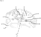
- FIG. 1 represents a rotating electrical machine 1 comprising a stator unit 2 comprising a position measuring device 3 according to one embodiment.
- the rotating electrical machine 1 may for example be an electric motor for an electric or hybrid motor vehicle.
- the invention also applies to other types of rotating electrical machine such as an alternator or a motor vehicle alternator-starter.
- the stator unit 2 includes a stator in which a winding is arranged.
- winding is meant a coil or several coils, for example based on copper.
- the rotating electrical machine 1 also comprises a rotor mounted for rotation with respect to the stator unit 2 along an axis of rotation X inside the winding.
- the stator unit 2 comprises a casing 4 surrounding the stator and the rotor to protect them.
- the casing 4 comprises at least one flange positioned at an axial end 6 of the rotary electrical machine 1 and which forms a bearing 5 guiding the shaft of the rotor in rotation.
- the bearing 5 extends generally in a plane perpendicular to the axis of rotation X.
- the position measuring device 3 is arranged in such a way as to be able to be rotated with respect to the bearing 5 and to the target of the rotor around the axis of rotation X of the rotor before its final fixing on the bearing 5.
- This calibration step is carried out using a calibration tool 7 cooperating with the position measuring device 3 so that the rotation of the calibration tool 7 causes the rotation of the position measuring device 3 in order to correct the angular position of the position sensor relative to the rotor target.
- the electrical phase difference between the position sensor signals and the motor voltages is measured.
- the position sensor is thus rotated until the desired phase shift is obtained.
- the electric motor is driven in rotation.
- the position measuring device 3 and the calibration tool 7 will be more particularly described subsequently with regard in particular to the figures 2 to 6 .
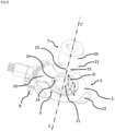
- FIG. 2 represents in particular the position measuring device 3 and the calibration tool 7 before their coupling, according to one embodiment.
- the position measuring device 3 comprises a sensor compartment 8 housing at least one position sensor measuring the position of the rotor with respect to the stator unit 2.
- the position measuring device 3 can comprise several position sensors for measuring rotor position and speed.
- the position sensors can be Hall effect sensors detecting the position and measuring the speed of the rotor by means of magnets forming part of the target attached to the rotor, for example.
- Other types of position sensor can be used such as optical sensors or inductive sensors.
- the position measuring device 3 is positioned at the level of the axial end 6 of the stator unit 2 so as to allow the position sensor to detect a rotating target connected to the rotor.
- the position measuring device 3 is thus located between the rotor and the bearing 5 and radially inside the stator unit 2.
- the position measuring device 3 comprises a fixing arm 9 projecting perpendicularly from the sensor compartment 8 towards the axis of rotation X, as shown in figure 1 And 2 .
- the fixing arm 9 further comprises a main portion 10 comprising an orifice 11 having a central axis C intended to be aligned with the axis of rotation X of the rotor when the position measuring device 3 is mounted on the bearing 5. orifice 11 is intended to receive the shaft of the rotor.
- the fixing arm 9 also comprises a peripheral portion 12 located around the main portion 10 and fixed to the main portion 10.
- the sensor compartment 8 and the main portion 10 of the fixing arm 9 are for example made of a polymer material while that the peripheral portion 12 is made of metal.
- the peripheral portion 12 can for example be overmolded in the main portion 10 during an overmolding operation so as to obtain a peripheral portion 12 integrated into the main portion 10.
- the peripheral portion 12 comprises in this embodiment three fixing holes 13 regularly distributed all around the orifice 11.
- Fixing means, such as screws 25, pass through the fixing holes 13 so as to fix the arm of fixing 9 on the bearing 5 of the stator unit 2.
- Each fixing hole 13 has an oblong and curved shape whose curvature has as its center the central axis C. The shape of the fixing holes 13 makes it possible to authorize the rotation of the position measuring device 3 during the calibration of the position sensors with the target of the rotor.
- the calibration step is carried out using a calibration tool 7 cooperating with the position measuring device 3, the calibration step being carried out after the positioning of the position measuring device 3 on the stator unit 2 and before its final fixing.
- the main portion 10 of the fixing arm 9 comprises three notches 14 made on the periphery of the orifice 11 and regularly distributed around the latter.
- Each notch 14 is advantageously spaced from the adjacent notches 14 by a protrusion 16 projecting axially from the main portion 10.
- the notches 14 have a depth, in the direction of the central axis C up to a wall bottom 17, equal to about 4 mm.
- Each notch 14 thus has two side walls 18 and a radially outer wall 19.
- the side walls 18 are arranged circumferentially on either side of the radially outer wall 19.
- the calibration tool 7 comprises a cylindrical body 20 of revolution around a central axis C′, and having at one end 21 three teeth 15 distributed regularly all around the periphery of the end 21.
- the number of teeth 15 and the number of notches 14 can vary as needed as long as there remains a match between the positioning of the teeth 15 and the positioning of the notches 14.
- each tooth 15 has a length in the direction of the central axis C', equal to approximately 4 mm. Each tooth 15 is thus configured to engage in one of the notches 14 of the position measuring device 3.
- Each tooth 15 has an axial end surface 22 located opposite the bottom wall 17 of a notch 14 when the calibration tool 7 is coupled with the position measuring device 3.
- Each tooth 15 also has a surface radially outer surface 23 located in the extension of the cylindrical body 20, and two side surfaces 24 located on either side of the radially outer surface 23.
- each side surface 24 of a tooth 15 is located opposite a side wall 18 of a notch 14.
- the radially outer surface 23 of the tooth 15 is located opposite the radially outer wall 19 of the notch 14.
- the central axis C of the orifice 11 coincides with the central axis C' of the cylindrical body 20.
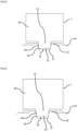
- THE figures 3 to 6 show different embodiments of the position measuring device 3 and the calibration tool 7, highlighting the coupling between a tooth 15 and a notch 14.
- the side walls 18 of the notch 14 and the side surfaces 24 of the tooth 15 are formed in radial planes passing through the central axis C of the orifice 11 or through the central axis C' of the cylindrical body 20 respectively so that each side wall 18 is parallel to a side surface 24.
- the side walls 18 are thus perpendicular to the bottom wall 17 while the side surfaces 24 are perpendicular to the axial end surface 22.
- the embodiment of the figure 4 differs from the embodiment of the picture 3 in that the side surfaces 24 of the tooth 15 are inclined at an angle, of 10° in the example shown, with respect to a radial plane passing through the central axis C′ of the cylindrical body 20.
- the inclination d one side surface 24 is opposite to the inclination of the other side surface 24.
- the inclination of the side surfaces 24 is made such that the tooth 15 has a circumferential dimension which narrows towards the surface of the tooth. axial end 22.
- the side surfaces 24 present an angle of 100° with the axial end surface 22.
- the embodiment of the figure 5 differs from the embodiment of the picture 3 in that the side walls 18 of the notch 14 are inclined at an angle, of 10° in the example shown, with respect to a radial plane passing through the central axis C of the orifice 11.
- the inclination of one side wall 18 is opposite to the inclination of the other side wall 18.
- the inclination of the side walls 18 is made so that the notch 14 has a circumferential dimension that narrows towards the wall bottom 17.
- the side walls 18 have an angle of 100° with the bottom wall 17.
- the embodiment of the figure 6 corresponds to a combination of the characteristics of the embodiment of the figure 4 and those of the embodiment of the figure 5 . Indeed, in this mode, the side walls 18 of the notch 14 and the side surfaces 24 of the tooth 15 are inclined at an angle of 10° in the example shown. Thus, each side surface 24 is parallel to a side wall 18.
- the inclination of the side walls 18 and/or the inclination of the side surfaces 24 makes it possible to guarantee contact between the notch 14 and the tooth 15 on either side of the notch 14, without worrying about a possible backlash. This increases the accuracy of the calibration.
- the radially outer wall 19 has the shape of an angular sector of a truncated cone of revolution around the central axis C and having a non-zero half-angle at the apex, for example of 10°.
- the inclination of the radially outer wall 19 is made so that the notch 14 has a radial dimension that narrows towards the bottom wall 17.
- the radially outer surface 23 has the shape of an angular sector of a truncated cone of revolution around the central axis C′ and having a half-angle at the non-zero vertex, for example 10°.
- the inclination of the radially outer surface 23 is made so that the tooth 15 has a radial dimension which tapers towards the axial end surface 22.
Landscapes
- Physics & Mathematics (AREA)
- General Physics & Mathematics (AREA)
- Engineering & Computer Science (AREA)
- Microelectronics & Electronic Packaging (AREA)
- Power Engineering (AREA)
Abstract
Description
- La présente invention concerne un dispositif de mesure de position pour unité de stator de machine électrique tournante, une unité de stator comprenant un tel dispositif de mesure de position et une machine électrique tournante comprenant cette unité de stator. La présence invention concerne également un outil de calibrage pour un tel dispositif de mesure de position ainsi qu'un procédé de calibrage d'un tel dispositif de mesure de position avec un outil de calibrage.
- L'invention se rapporte notamment au domaine des machines électriques tournantes telles que les moteurs électriques, les alternateurs, ou les alterno-démarreurs pour les véhicules automobiles.
- Il est connu du document
FR3108974 - Les machines électriques tournantes comprennent une unité de stator comportant un stator muni d'au moins un bobinage en cuivre. Les machines électriques tournantes comprennent également un rotor monté en rotation dans l'unité de stator et par rapport à celle-ci. L'unité de stator comprend un carter entourant et protégeant le stator.
- La machine électrique comprend un dispositif de mesure de position comportant un compartiment de capteur destiné à loger au moins un capteur de position mesurant la position du rotor par rapport au stator. L'utilisation de plusieurs capteurs de position permet également de mesurer la position et la vitesse du rotor.
- Le dispositif de mesure de position est positionné radialement à l'intérieur du bobinage, et en regard d'une cible en rotation fixée au rotor, de façon à permettre au capteur de position de détecter la cible. Par exemple, le capteur de position peut être un capteur à effet Hall détectant des aimants faisant partie de la cible, ou un capteur optique.
- Le dispositif de mesure de position comprend un bras de fixation faisant saillie perpendiculairement par rapport au compartiment de capteur vers l'axe de rotation du rotor.
- Le carter de l'unité de stator comprend un palier ou flasque positionné à une extrémité axiale de la machine électrique tournante. Le bras de fixation comprend une portion principale et une portion d'extrémité fixée sur ce palier.
- La portion principale comprend un orifice présentant un axe central aligné avec l'axe de rotation du rotor et au travers duquel passe l'arbre du rotor.
- Le dispositif de mesure de position est agencé de façon à pouvoir être tourné à l'aide d'un outil de calibrage par rapport au palier et à la cible du rotor autour de l'axe de rotation du rotor, avant sa fixation définitive sur le palier.
- Ceci permet de calibrer ou synchroniser manuellement le signal de la cible du rotor avec les capteurs de position. Le dispositif de mesure de position présente des encoches coopérant chacune avec une dent de l'outil de calibrage de sorte que la rotation de l'outil de calibrage entraine la rotation du dispositif de mesure de position afin de corriger la position angulaire du capteur de position par rapport à la cible du rotor.
- Toutefois, la conception des dispositifs de mesure de position du document
FR3108974 - Une idée à la base de l'invention est d'améliorer l'accouplement entre le dispositif de mesure de position et l'outil de calibrage afin d'améliorer la précision du positionnement a angulaire du dispositif de mesure de position par rapport à l'unité de stator.
- Selon un mode de réalisation, l'invention fournit un dispositif de mesure de position destinée à une machine électrique tournante comportant une unité de stator et un rotor monté en rotation dans et par rapport à l'unité de stator suivant un axe de rotation, le dispositif de mesure de position comprenant un capteur de position destiné à mesurer la position du rotor par rapport à l'unité de stator et logé dans un compartiment de capteur, le dispositif de mesure de position étant destiné à être positionné dans une zone d'extrémité axiale de l'unité de stator de façon à permettre au capteur de position de détecter une cible en rotation reliée au rotor, le dispositif de mesure de position comprenant un bras de fixation faisant saillie par rapport au compartiment de capteur vers l'axe de rotation,
- dans lequel le bras de fixation comporte un orifice destiné à recevoir un arbre du rotor et présentant un axe central destiné à être aligné avec l'axe de rotation du rotor,
- et dans lequel le bras de fixation comporte au moins une encoche réalisée sur la périphérie de l'orifice, l'encoche présentant une profondeur, dans la direction de l'axe central jusqu'à une paroi de fond, supérieure ou égale à 2 mm, l'encoche étant configurée pour accueillir une dent d'un outil de calibrage.
- Grâce à ces caractéristiques, la profondeur de l'encoche du dispositif de mesure de position permet d'améliorer l'accouplement entre le dispositif de mesure de position et l'outil de calibrage ce qui a pour avantage de limiter fortement des désaccouplements inopinés lors du calibrage. En effet, il a été constaté par les inventeurs qu'une encoche ayant une profondeur inférieure ou égale à 1,5 mm ne permettait pas d'avoir un accouplement suffisamment fiable.
- Selon des modes de réalisation, un tel dispositif de mesure de position peut comporter une ou plusieurs des caractéristiques suivantes.
- Selon un mode de réalisation, l'encoche présente une profondeur comprise entre 2 et 5 mm, par exemple égale à 4 mm.
- Selon un mode de réalisation, l'encoche comporte deux parois latérales et une paroi radialement externe, les parois latérales étant disposées de manière circonférentielle de part et d'autre de la paroi radialement externe.
- Selon un mode de réalisation, les parois latérales comportent une première paroi latérale et une deuxième paroi latérale, la première paroi latérale étant formée dans un plan incliné d'un premier angle non nul par rapport à un plan radial passant par l'axe central de l'orifice, la deuxième paroi latérale étant formée dans un plan incliné d'un deuxième angle non nul par rapport à un plan radial passant par l'axe central de l'orifice, le premier angle et le deuxième angle étant opposées, l'inclinaison des parois latérales étant configurée pour que l'encoche ait une dimension circonférentielle se rétrécissant en allant vers la paroi de fond.
- Ainsi, l'inclinaison des parois latérales de l'encoche permet de garantir un contact entre l'encoche et la dent de part et d'autre de l'encoche, sans se soucier d'un éventuel jeu, comme lorsque les parois latérales ne sont pas inclinées. Cela permet ainsi d'augmenter la précision du calibrage.
- Selon un mode de réalisation, le premier angle et le deuxième angle sont compris en valeur absolue entre 5 et 35°, de préférence entre 5 et 15°, par exemple égal à 10°.
- Selon un mode de réalisation, la paroi radialement externe présente la forme d'un secteur angulaire d'un tronc de cône de révolution autour de l'axe central et ayant un demi-angle au sommet non nul, l'inclinaison de la paroi radialement externe étant configurée pour que l'encoche ait une dimension radiale se rétrécissant en allant vers la paroi de fond.
- Ainsi, l'inclinaison de la paroi radialement externe, due à la forme tronconique, de l'encoche permet de garantir un contact entre l'encoche et la dent, sans se soucier d'un éventuel jeu, comme lorsque la paroi radialement externe n'est pas inclinée. Cela permet ainsi d'augmenter la précision du calibrage.
- Selon un mode de réalisation, le demi-angle au sommet est compris entre 5 et 35°, de préférence entre 5 et 15°, par exemple égal à 10°.
- Selon un mode de réalisation, le bras de fixation comporte une pluralité d'encoches, par exemple deux, trois ou quatre.
- Selon un mode de réalisation, les encoches sont réparties régulièrement tout autour de la périphérie de l'orifice, par exemple au nombre de trois.
- Selon un mode de réalisation, le bras de fixation comporte une portion principale, dans laquelle est réalisée l'orifice, et une portion périphérique située autour de la portion principale et fixée à la portion principale.
- Selon un mode de réalisation, le compartiment de capteur et la portion principale du bras de fixation sont réalisés dans un matériau polymère.
- Selon un mode de réalisation, la portion périphérique est réalisée en métal.
- Selon un mode de réalisation, la portion périphérique comprend une pluralité de trous de fixation, des moyens de fixation étant destinés à traverser les trous de fixations du bras de fixation de sorte à fixer le bras de fixation sur un palier de l'unité de stator.
- Selon un mode de réalisation, la portion périphérique est surmoulée dans la portion principale du bras de fixation lors d'une opération de surmoulage de façon à obtenir une portion périphérique intégré à la portion principale.
- Ceci permet de simplifier le processus de fabrication du dispositif de mesure de position. Une seule étape de moulage est nécessaire. Il y a moins de pièces à assembler et à gérer.
- Selon un mode de réalisation, chaque trou de fixation présente une forme oblongue et incurvée, la courbure des trous de fixation ayant pour centre de courbure l'axe central.
- Selon un mode de réalisation, les trous de fixation sont répartis régulièrement tout autour de l'orifice, les trous de fixation étant par exemple au nombre de 3.
- Selon un mode de réalisation, chaque encoche débouche radialement dans l'orifice.
- Selon un mode de réalisation, l'invention fournit aussi un outil de calibrage destiné à calibrer un dispositif de mesure de position pour unité de stator de machine électrique tournante comprenant un stator dans lequel est disposé un bobinage, la machine électrique tournante comprenant un rotor monté en rotation dans et par rapport à l'unité de stator suivant un axe de rotation,
dans lequel l'outil de calibrage comporte un corps cylindrique de révolution autour d'un axe central présentant à une extrémité au moins une dent, la dent présentant une longueur dans la direction de l'axe central supérieure ou égale à 2 mm, la dent étant configurée pour s'engager dans une encoche d'un dispositif de mesure de position. - Grâce à ces caractéristiques, et de manière analogue à la profondeur de l'encoche, la longueur de la dent de l'outil de calibrage permet d'améliorer l'accouplement entre le dispositif de mesure de position et l'outil de calibrage ce qui a pour avantage de limiter fortement des désaccouplements inopinés lors du calibrage.
- Selon un mode de réalisation, la dent présente une longueur comprise entre 2 et 5 mm, par exemple égale à 4 mm.
- Selon un mode de réalisation, la dent comporte une surface d'extrémité axiale destinée à être en regard d'une paroi de fond d'une encoche de dispositif de mesure de position, une surface radialement externe située dans le prolongement du corps cylindrique, et deux surfaces latérales située de part et d'autre de la surface radialement externe.
- Selon un mode de réalisation, les surfaces latérales comportent une première surface latérale et une deuxième surface latérale, la première surface latérale étant formée dans un plan incliné d'un premier angle non nul par rapport à un plan radial passant par l'axe central du corps cylindrique, la deuxième surface latérale étant formée dans un plan incliné d'un deuxième angle non nul par rapport à un plan radial passant par l'axe central de l'orifice, le premier angle et le deuxième angle étant opposées, l'inclinaison des surfaces latérales étant configurée pour que la dent ait une dimension circonférentielle se rétrécissant en allant vers la surface d'extrémité axiale.
- Selon un mode de réalisation, le premier angle et le deuxième angle sont compris en valeur absolue entre 5 et 35°, de préférence entre 5 et 15°, par exemple égal à 10°.
- Selon un mode de réalisation, la surface radialement externe présente la forme d'un secteur angulaire d'un tronc de cône de révolution autour de l'axe central et ayant un demi-angle au sommet non nul, l'inclinaison de la surface radialement externe étant configurée pour que la dent ait une dimension radiale se rétrécissant en allant vers la surface d'extrémité axiale.
- Selon un mode de réalisation, le demi-angle au sommet est compris entre 5 et 35°, de préférence entre 5 et 15°, par exemple égal à 10°.
- Selon un mode de réalisation, la dent est réalisée à une périphérie de l'extrémité du corps cylindrique.
- Selon un mode de réalisation, le bras de fixation comporte une pluralité de dents, par exemple deux, trois ou quatre.
- Selon un mode de réalisation, les dents sont réparties régulièrement tout autour d'une périphérie de l'extrémité du corps cylindrique.
- Selon un mode de réalisation, l'invention fournit aussi un ensemble comportant un dispositif de mesure de position précité et un outil de calibrage précité.
- Selon un mode de réalisation, l'invention fournit aussi une unité de stator de machine électrique tournante comprenant un stator, dans laquelle l'unité de stator comprend un dispositif de mesure de position précité, le dispositif de mesure de position étant positionné dans une zone d'extrémité axiale de l'unité de stator de façon à permettre au capteur de position de détecter une cible en rotation reliée au rotor.
- Selon un mode de réalisation, l'invention fournit aussi une machine électrique tournante comprenant une unité de stator précitée, et un rotor monté en rotation dans et par rapport à l'unité de stator suivant l'axe de rotation.
- Selon un mode de réalisation, l'invention fournit aussi un procédé de calibrage d'un dispositif de mesure de position dans une machine électrique tournante, dans lequel le procédé comprend les étapes suivantes :
- fournir une machine électrique tournante comprenant une unité de stator, et un rotor monté en rotation dans et par rapport à l'unité de stator suivant un axe de rotation, l'unité de stator comprenant un stator muni d'un bobinage, et un dispositif de mesure de position précité,
- fournir un outil de calibrage précité,
- mettre en position le dispositif de mesure de position dans une zone d'extrémité axiale de l'unité de stator,
- accoupler l'outil de calibrage avec le dispositif de mesure de position en positionnant l'au moins une dent dans l'au moins une encoche,
- calibrer le dispositif de mesure de position avec la cible reliée au rotor à l'aide de l'outil de calibrage,
- fixer le dispositif de mesure de position à l'unité de stator et désaccoupler l'outil de calibrage du dispositif de mesure de position.
- L'invention sera mieux comprise, et d'autres buts, détails, caractéristiques et avantages de celle-ci apparaîtront plus clairement au cours de la description suivante de plusieurs modes de réalisation particuliers de l'invention, donnés uniquement à titre illustratif et non limitatif, en référence aux dessins annexés.
- [
Fig. 1 ] Lafigure 1 représente une vue en perspective partielle d'une machine électrique tournante comprenant une unité de stator et un dispositif de mesure de position selon un mode de réalisation - [
Fig. 2 ] Lafigure 2 est une vue en perspective d'un dispositif de mesure de position et d'un outil de calibrage avant accouplement, selon un mode de réalisation. - [
Fig. 3 ] Lafigure 3 est une vue en coupe selon le plan III de lafigure 2 lorsque l'outil de calibrage est accouplé avec le dispositif de mesure de position, selon un premier mode de réalisation. - [
Fig. 4 ] Lafigure 4 est une vue en coupe selon le plan III de lafigure 2 lorsque l'outil de calibrage est accouplé avec le dispositif de mesure de position, selon un deuxième mode de réalisation. - [
Fig. 5 ] Lafigure 5 est une vue en coupe selon le plan III de lafigure 2 lorsque l'outil de calibrage est accouplé avec le dispositif de mesure de position, selon un troisième mode de réalisation. - [
Fig. 6 ] Lafigure 6 est une vue en coupe selon le plan III de lafigure 2 lorsque l'outil de calibrage est accouplé avec le dispositif de mesure de position, selon un quatrième mode de réalisation. - Dans la description et les revendications, on utilisera, les orientations « axiale » et « radiale » pour désigner, selon les définitions données dans la description, des éléments du dispositif de mesure de position et de l'outil de calibrage. Par convention, l'axe central de l'orifice du bras de fixation ou de l'outil de calibrage définit l'orientation « axiale ». L'orientation « radiale » est dirigée orthogonalement à l'axe X et, de l'intérieur vers l'extérieur en s'éloignant dudit axe et l'orientation « circonférentielle » est dirigée orthogonalement à l'axe central et orthogonalement à la direction radiale. Les termes « externe » sont utilisés pour définir la position relative d'un élément par rapport à un autre, par référence à l'axe central, un élément éloigné de l'axe central est ainsi qualifié d'externe par opposition à un élément interne situé radialement plus proche de l'axe central.
- La
figure 1 représente une machine électrique tournante 1 comprenant une unité de stator 2 comportant un dispositif de mesure de position 3 selon un mode de réalisation. - La machine électrique tournante 1 peut être par exemple un moteur électrique pour véhicule automobile électrique ou hybride. L'invention s'applique également à d'autres types de machine électrique tournante tel qu'un alternateur ou un alterno-démarreur de véhicule automobile.
- L'unité de stator 2 comprend un stator dans lequel est disposé un bobinage. On entend par bobinage, une bobine ou plusieurs bobines, par exemple à base de cuivre. La machine électrique tournante 1 comprend également un rotor monté en rotation par rapport à l'unité de stator 2 suivant un axe de rotation X à l'intérieur du bobinage.
- L'unité de stator 2 comprend un carter 4 entourant le stator et le rotor pour les protéger. Le carter 4 comprend au moins un flasque positionné à une extrémité axiale 6 de la machine électrique tournante 1 et qui forme un palier 5 guidant en rotation l'arbre du rotor. Le palier 5 s'étend de manière générale dans un plan perpendiculaire à l'axe de rotation X.
- Le dispositif de mesure de position 3 est agencé de façon à pouvoir être tourné par rapport au palier 5 et à la cible du rotor autour de l'axe de rotation X du rotor avant sa fixation définitive sur le palier 5.
- Ceci permet de calibrer le signal de la cible du rotor avec les capteurs de position. Cette étape de calibrage est réalisée à l'aide d'un outil de calibrage 7 coopérant avec le dispositif de mesure de position 3 de sorte que la rotation de l'outil de calibrage 7 entraine la rotation du dispositif de mesure de position 3 afin de corriger la position angulaire du capteur de position par rapport à la cible du rotor. En effet, lors du calibrage, le déphasage électrique entre les signaux du capteur de position et les tensions du moteur est mesuré. Le capteur de position est ainsi tourné jusqu'à obtenir le déphasage voulu. Pour le calibrage, le moteur électrique est entrainé en rotation.
- Le dispositif de mesure de position 3 et l'outil de calibrage 7 seront plus particulièrement décrits par la suite au regard notamment des
figures 2 à 6 . - La
figure 2 représente notamment le dispositif de mesure de position 3 et l'outil de calibrage 7 avant leur accouplement, selon un mode de réalisation. - Le dispositif de mesure de position 3 comprend un compartiment de capteur 8 logeant au moins un capteur de position mesurant la position du rotor par rapport à l'unité de stator 2. Le dispositif de mesure de position 3 peut comprendre plusieurs capteurs de position pour mesurer la position et la vitesse du rotor. Les capteurs de position peuvent être des capteurs à effet Hall détectant la position et mesurant la vitesse du rotor au moyen d'aimants faisant partie de la cible fixée au rotor, par exemple. D'autres types de capteur de position peuvent être utilisés comme des capteurs optiques ou des capteurs inductifs.
- Le dispositif de mesure de position 3 est positionné au niveau de l'extrémité axiale 6 de l'unité de stator 2 de façon à permettre au capteur de position de détecter une cible en rotation reliée au rotor. Le dispositif de mesure de position 3 est ainsi situé entre le rotor et le palier 5 et radialement à l'intérieur de l'unité de stator 2.
- Le dispositif de mesure de position 3 comprend un bras de fixation 9 faisant saillie perpendiculairement du compartiment de capteur 8 vers l'axe de rotation X, comme représenté en
figures 1 et2 . - Le bras de fixation 9 comporte en outre une portion principale 10 comprenant un orifice 11 présentant un axe central C destiné à être aligné avec l'axe de rotation X du rotor lorsque le dispositif de mesure de position 3 est monté sur le palier 5. L'orifice 11 est destiné à recevoir l'arbre du rotor.
- Le bras de fixation 9 comporte également une portion périphérique 12 située autour de la portion principale 10 et fixée à la portion principale 10. Le compartiment de capteur 8 et la portion principale 10 du bras de fixation 9 sont par exemple réalisés dans un matériau polymère tandis que la portion périphérique 12 est réalisée en métal.
- La portion périphérique 12 peut par exemple être surmoulé dans la portion principale 10 lors d'une opération de surmoulage de façon à obtenir une portion périphérique 12 intégré à la portion principale 10.
- Comme visible en
figure 2 , la portion périphérique 12 comprend dans ce mode de réalisation trois trous de fixation 13 répartis régulièrement tout autour de l'orifice 11. Des moyens de fixation, tels que des vis 25, traversent les trous de fixations 13 de sorte à fixer le bras de fixation 9 sur le palier 5 de l'unité de stator 2. Chaque trou de fixation 13 présente une forme oblongue et incurvée dont la courbure a pour centre l'axe central C. La forme des trous de fixation 13 permet d'autoriser la rotation du dispositif de mesure de position 3 lors du calibrage des capteurs de position avec la cible du rotor. - Comme énoncé précédemment, l'étape de calibrage est réalisée à l'aide d'un outil de calibrage 7 coopérant avec le dispositif de mesure de position 3, l'étape de calibrage étant réalisée après la mise en position du dispositif de mesure de position 3 sur l'unité de stator 2 et avant sa fixation définitive.
- Cette coopération est réalisée à l'aide d'encoches 14 réalisées sur le dispositif de mesure de position 3 et de dents 15 réalisées sur l'outil de calibrage 7.
- En effet, comme représenté sur la
figure 2 , la portion principale 10 du bras de fixation 9 comporte trois encoches 14 réalisées sur la périphérie de l'orifice 11 et régulièrement réparties autour de celui-ci. Chaque encoche 14 est avantageusement espacée des encoches 14 adjacentes par une protubérance 16 faisant saillie axialement de la portion principale 10. Dans l'exemple représenté, les encoches 14 présentent une profondeur, dans la direction de l'axe central C jusqu'à une paroi de fond 17, égale à environ 4 mm. - Chaque encoche 14 comporte ainsi deux parois latérales 18 et une paroi radialement externe 19. Les parois latérales 18 sont disposées de manière circonférentielle de part et d'autre de la paroi radialement externe 19.
- L'outil de calibrage 7 comporte un corps cylindre 20 de révolution autour d'un axe central C', et présentant à une extrémité 21 trois dents 15 réparties régulièrement tout autour de la périphérie de l'extrémité 21. Dans d'autres modes de réalisation non représentés, le nombre de dents 15 et le nombre d'encoches 14 peuvent varier au besoin tant qu'il reste une concordance entre le positionnement des dents 15 avec le positionnement des encoches 14.
- De la même manière que pour les encoches 14, dans l'exemple représenté, chaque dent 15 présente une longueur dans la direction de l'axe central C', égale à environ 4 mm. Chaque dent 15 est ainsi configurée pour s'engager dans l'une des encoches 14 du dispositif de mesure de position 3.
- Chaque dent 15 comporte une surface d'extrémité axiale 22 située en regard de la paroi de fond 17 d'une encoche 14 lorsque l'outil de calibrage 7 est accouplé avec le dispositif de mesure de position 3. Chaque dent 15 comporte également une surface radialement externe 23 située dans le prolongement du corps cylindrique 20, et deux surface latérales 24 située de part et d'autre de la surface radialement externe 23.
- Lors de l'accouplement, chaque surface latérale 24 d'une dent 15 est située en regard d'une paroi latérale 18 d'une encoche 14. De la même manière, la surface radialement externe 23 de la dent 15 est située en regard de la paroi radialement externe 19 de l'encoche 14. Lors de l'accouplement, l'axe central C de l'orifice 11 coïncide avec l'axe central C' du corps cylindrique 20.
- Les
figures 3 à 6 montrent différents modes de réalisation du dispositif de mesure de position 3 et de l'outil de calibrage 7, en mettant en évidence l'accouplement entre une dent 15 et une encoche 14. - Dans le mode de réalisation de la
figure 3 , les parois latérales 18 de l'encoche 14 et les surfaces latérales 24 de la dent 15 sont formés dans des plans radiaux passant par l'axe central C de l'orifice 11 ou par l'axe central C' du corps cylindrique 20 respectivement de sorte que chaque paroi latérale 18 est parallèle à une surface latérale 24. Les parois latérales 18 sont ainsi perpendiculaires à la paroi de fond 17 tandis que les surfaces latérales 24 sont perpendiculaires à la surface d'extrémité axiale 22. - Le mode de réalisation de la
figure 4 diffère du mode de réalisation de lafigure 3 en ce que les surfaces latérales 24 de la dent 15 sont inclinés d'un angle, de 10° dans l'exemple représenté, par rapport à un plan radial passant par l'axe central C' du corps cylindrique 20. L'inclinaison d'une surface latérale 24 est opposée à l'inclinaison de l'autre surface latérale 24. De plus, l'inclinaison des surfaces latérales 24 est réalisée de sorte que la dent 15 présente une dimension circonférentielle se rétrécissant en allant vers la surface d'extrémité axiale 22. Ainsi, les surfaces latérales 24 présentent un angle de 100° avec la surface d'extrémité axiale 22. - Le mode de réalisation de la
figure 5 diffère du mode de réalisation de lafigure 3 en ce que les parois latérales 18 de l'encoche 14 sont inclinés d'un angle, de 10° dans l'exemple représenté, par rapport à un plan radial passant par l'axe central C de l'orifice 11. L'inclinaison d'une paroi latérale 18 est opposée à l'inclinaison de l'autre paroi latérale 18. De plus, l'inclinaison des parois latérales 18 est réalisée de sorte que l'encoche 14 présente une dimension circonférentielle se rétrécissant en allant vers la paroi de fond 17. Ainsi, les parois latérales 18 présentent un angle de 100° avec la paroi de fond 17. - Le mode de réalisation de la
figure 6 correspond à une combinaison des caractéristiques du mode de réalisation de lafigure 4 et de celles du mode de réalisation de lafigure 5 . En effet, dans ce mode, les parois latérales 18 de l'encoche 14 et les surfaces latérales 24 de la dent 15 sont inclinés d'un angle de 10° dans l'exemple représenté. Ainsi, chaque surface latérale 24 est parallèle à une paroi latérale 18. - L'inclinaison des parois latérales 18 et/ou l'inclinaison des surfaces latérales 24 permet de garantir un contact entre l'encoche 14 et la dent 15 de part et d'autre de l'encoche 14, sans se soucier d'un éventuel jeu. Cela permet ainsi d'augmenter la précision du calibrage.
- De plus, avantageusement, la paroi radialement externe 19 présente la forme d'un secteur angulaire d'un tronc de cône de révolution autour de l'axe central C et ayant un demi-angle au sommet non nul, par exemple de 10°. L'inclinaison de la paroi radialement externe19 est réalisée de sorte que l'encoche 14 ait une dimension radiale se rétrécissant en allant vers la paroi de fond 17.
- De la même manière, avantageusement, la surface radialement externe 23 présente la forme d'un secteur angulaire d'un tronc de cône de révolution autour de l'axe central C' et ayant un demi-angle au sommet non nul, par exemple de 10°. L'inclinaison de la surface radialement externe 23 est réalisée de sorte que la dent 15 ait une dimension radiale se rétrécissant en allant vers la surface d'extrémité axiale 22.
- L'inclinaison de la paroi radialement externe 19 et/ou de la surface radialement externe 23, due à la forme tronconique, de l'encoche 14 et/ou de la dent 15 permet de garantir un contact entre l'encoche 14 et la dent 15, sans se soucier d'un éventuel jeu. Cela permet ainsi d'augmenter la précision du calibrage.
- Bien que l'invention ait été décrite en liaison avec plusieurs modes de réalisation particuliers, il est bien évident qu'elle n'y est nullement limitée et qu'elle comprend tous les équivalents techniques des moyens décrits ainsi que leurs combinaisons si celles-ci entrent dans le cadre de l'invention.
- L'usage du verbe « comporter », « comprendre » ou « inclure » et de ses formes conjuguées n'exclut pas la présence d'autres éléments ou d'autres étapes que ceux énoncés dans une revendication.
- Dans les revendications, tout signe de référence entre parenthèses ne saurait être interprété comme une limitation de la revendication.
Claims (14)
- Dispositif de mesure de position (3) destinée à une machine électrique tournante (1) comportant une unité de stator (2) et un rotor monté en rotation dans et par rapport à l'unité de stator (2) suivant un axe de rotation (X), le dispositif de mesure de position (3) comprenant un capteur de position destiné à mesurer la position du rotor par rapport à l'unité de stator (2) et logé dans un compartiment de capteur (8) , le dispositif de mesure de position (3) étant destiné à être positionné dans une zone d'extrémité axiale (6) de l'unité de stator (2) de façon à permettre au capteur de position de détecter une cible en rotation reliée au rotor, le dispositif de mesure de position (3) comprenant un bras de fixation (9) faisant saillie par rapport au compartiment de capteur (8) vers l'axe de rotation (X),dans lequel le bras de fixation (9) comporte un orifice (11) destiné à recevoir un arbre du rotor et présentant un axe central (C) destiné à être aligné avec l'axe de rotation (X) du rotor,et dans lequel le bras de fixation (9) comporte au moins une encoche (14) réalisées sur la périphérie de l'orifice (11), l'encoche (14) présentant une profondeur, dans la direction de l'axe central jusqu'à une paroi de fond (17), supérieure ou égale à 2 mm, l'encoche (14) étant configurée pour accueillir une dent (15) d'un outil de calibrage (7).
- Dispositif de mesure de position (3) selon la revendication 1, dans lequel l'encoche (14) comporte deux parois latérales (18) et une paroi radialement externe (19), les parois latérales (18) étant disposées de manière circonférentielle de part et d'autre de la paroi radialement externe (19).
- Dispositif de mesure de position (3) selon la revendication 1 ou la revendication 2, dans lequel les parois latérales (18) comportent une première paroi latérale et une deuxième paroi latérale, la première paroi latérale étant formée dans un plan incliné d'un premier angle non nul par rapport à un plan radial passant par l'axe central de l'orifice (11), la deuxième paroi latérale étant formée dans un plan incliné d'un deuxième angle non nul par rapport à un plan radial passant par l'axe central de l'orifice (11), le premier angle et le deuxième angle étant opposées, l'inclinaison des parois latérales (18) étant configurée pour que l'encoche ait une dimension circonférentielle se rétrécissant en allant vers la paroi de fond (17).
- Dispositif de mesure de position (3) selon la revendication 3, dans lequel le premier angle et le deuxième angle sont compris en valeur absolue entre 5 et 35°.
- Dispositif de mesure de position (3) selon l'une des revendications 2 à 4, dans lequel la paroi radialement externe (19) présente la forme d'un secteur angulaire d'un tronc de cône de révolution autour de l'axe central et ayant un demi-angle au sommet non nul, l'inclinaison de la paroi radialement externe (19) étant configurée pour que l'encoche (14) ait une dimension radiale se rétrécissant en allant vers la paroi de fond (17).
- Dispositif de mesure de position (3) selon l'une des revendications 1 à 5, dans lequel le bras de fixation (9) comporte une portion principale (10), dans laquelle est réalisée l'orifice (11), et une portion périphérique (12) située autour de la portion principale (10) et fixée à la portion principale (10).
- Outil de calibrage (7) destiné à calibrer un dispositif de mesure de position (3) pour unité de stator (2) de machine électrique tournante (1) comprenant un stator dans lequel est disposé un bobinage, la machine électrique tournante (1) comprenant un rotor monté en rotation dans et par rapport à l'unité de stator (2) suivant un axe de rotation,
dans lequel l'outil de calibrage (7) comporte un corps cylindrique (20) de révolution autour d'un axe central (C') présentant à une extrémité (21) au moins une dent (15), la dent (15) présentant une longueur dans la direction de l'axe central supérieur ou égal à 2 mm, la dent (15) étant configurée pour s'engager dans une encoche d'un dispositif de mesure de position (3). - Outil de calibrage (7) selon la revendication 7, dans lequel la dent (15) comporte une surface d'extrémité axiale (22) destinée à être en regard d'une paroi de fond (17) d'une encoche de dispositif de mesure de position (3), une surface radialement externe (23) située dans le prolongement du corps cylindrique (20), et deux surfaces latérales (24) située de part et d'autre de la surface radialement externe (23).
- Outil de calibrage (7) selon la revendication 8, dans lequel les surfaces latérales (24) comportent une première surface latérale et une deuxième surface latérale, la première surface latérale étant formée dans un plan incliné d'un premier angle non nul par rapport à un plan radial passant par l'axe central du corps cylindrique (20), la deuxième surface latérale étant formée dans un plan incliné d'un deuxième angle non nul par rapport à un plan radial passant par l'axe central de l'orifice (11), le premier angle et le deuxième angle étant opposées, l'inclinaison des surfaces latérales (24) étant configurée pour que la dent (15) ait une dimension circonférentielle se rétrécissant en allant vers la surface d'extrémité axiale (22).
- Outil de calibrage (7) selon la revendication 9, dans lequel le premier angle et le deuxième angle sont compris en valeur absolue entre 5 et 35°.
- Outil de calibrage (7) selon l'une des revendications 8 à 10, dans lequel la surface radialement externe (23) présente la forme d'un secteur angulaire d'un tronc de cône de révolution autour de l'axe central et ayant un demi-angle au sommet non nul, l'inclinaison de la surface radialement externe (23) étant configurée pour que la dent ait une dimension radiale se rétrécissant en allant vers la surface d'extrémité axiale (22).
- Outil de calibrage (7) selon l'une des revendications 7 à 11, dans lequel la dent (15) est réalisée à une périphérie de l'extrémité (21) du corps cylindrique (20).
- Ensemble comportant un dispositif de mesure de position (3) selon l'une des revendications 1 à 6 et un outil de calibrage (7) selon l'une des revendications 7 à 12.
- Procédé de calibrage (7) d'un dispositif de mesure de position (3) dans une machine électrique tournante (1), dans lequel le procédé comprend les étapes suivantes :- fournir une machine électrique tournante (1) comprenant une unité de stator (2), et un rotor monté en rotation dans et par rapport à l'unité de stator (2) suivant un axe de rotation, l'unité de stator (2) comprenant un stator muni d'un bobinage, et un dispositif de mesure de position (3) selon l'une des revendications 1 à 6,- fournir un outil de calibrage (7) selon l'une des revendications 7 à 12,- mettre en position le dispositif de mesure de position (3) dans une zone d'extrémité axiale (6) de l'unité de stator (2),- accoupler l'outil de calibrage (7) avec le dispositif de mesure de position (3) en positionnant l'au moins une dent (15) dans l'au moins une encoche (14),- calibrer le dispositif de mesure de position (3) avec la cible reliée au rotor à l'aide de l'outil de calibrage (7),- fixer le dispositif de mesure de position (3) à l'unité de stator (2) et désaccoupler l'outil de calibrage (7) du dispositif de mesure de position (3).
Applications Claiming Priority (1)
| Application Number | Priority Date | Filing Date | Title |
|---|---|---|---|
| FR2113854A FR3130961B1 (fr) | 2021-12-17 | 2021-12-17 | Dispositif de mesure de position pour unité de stator de machine électrique tournante |
Publications (2)
| Publication Number | Publication Date |
|---|---|
| EP4198459A1 true EP4198459A1 (fr) | 2023-06-21 |
| EP4198459B1 EP4198459B1 (fr) | 2024-12-04 |
Family
ID=80735419
Family Applications (1)
| Application Number | Title | Priority Date | Filing Date |
|---|---|---|---|
| EP22206421.4A Active EP4198459B1 (fr) | 2021-12-17 | 2022-11-09 | Dispositif de mesure de position pour unité de stator de machine électrique tournante |
Country Status (4)
| Country | Link |
|---|---|
| US (1) | US20230194316A1 (fr) |
| EP (1) | EP4198459B1 (fr) |
| CN (1) | CN116266728A (fr) |
| FR (1) | FR3130961B1 (fr) |
Citations (2)
| Publication number | Priority date | Publication date | Assignee | Title |
|---|---|---|---|---|
| FR3051999A1 (fr) * | 2016-05-31 | 2017-12-01 | Valeo Equip Electr Moteur | Machine electrique tournante munie d'une plaque de maintien d'un capteur de position angulaire du rotor |
| FR3108974A1 (fr) | 2020-04-06 | 2021-10-08 | Valeo Equipements Electriques Moteur | Dispositif de mesure de position de rotor pour unité de stator de machine électrique tournante |
-
2021
- 2021-12-17 FR FR2113854A patent/FR3130961B1/fr active Active
-
2022
- 2022-11-09 EP EP22206421.4A patent/EP4198459B1/fr active Active
- 2022-12-16 US US18/067,351 patent/US20230194316A1/en not_active Abandoned
- 2022-12-16 CN CN202211622764.5A patent/CN116266728A/zh active Pending
Patent Citations (2)
| Publication number | Priority date | Publication date | Assignee | Title |
|---|---|---|---|---|
| FR3051999A1 (fr) * | 2016-05-31 | 2017-12-01 | Valeo Equip Electr Moteur | Machine electrique tournante munie d'une plaque de maintien d'un capteur de position angulaire du rotor |
| FR3108974A1 (fr) | 2020-04-06 | 2021-10-08 | Valeo Equipements Electriques Moteur | Dispositif de mesure de position de rotor pour unité de stator de machine électrique tournante |
Also Published As
| Publication number | Publication date |
|---|---|
| CN116266728A (zh) | 2023-06-20 |
| FR3130961A1 (fr) | 2023-06-23 |
| US20230194316A1 (en) | 2023-06-22 |
| FR3130961B1 (fr) | 2023-12-22 |
| EP4198459B1 (fr) | 2024-12-04 |
Similar Documents
| Publication | Publication Date | Title |
|---|---|---|
| EP2160819B1 (fr) | Systeme de support d'arbre pour moteur electrique, moteur electrique et procede de montage | |
| FR3077880A1 (fr) | Capteur de couple integrant un capteur de position angulaire d'un element en rotation | |
| FR3049323B1 (fr) | "couronne de differentiel equipee d'une cible de mesure de sa vitesse de rotation et agencement dans une boite de vitesses" | |
| FR2645276A1 (fr) | Capteur de la vitesse des roues d'un vehicule pour un essieu-moteur | |
| FR2844877A1 (fr) | Procede pour l'equilibrage rotatif d'un rotor de turbocompresseur avec machine electrique rotative | |
| EP1196787B1 (fr) | Palier a roulement instrumente | |
| EP4198459B1 (fr) | Dispositif de mesure de position pour unité de stator de machine électrique tournante | |
| WO2001055730A1 (fr) | Dispositif de palier a roulement instrumente avec pre-indexation angulaire temporaire du codeur par rapport au capteur | |
| EP0153887B1 (fr) | Dispositif et outillage de correction de balourd d'un rotor de turbomachine et procédé pour la mise en oeuvre | |
| FR2685568A1 (fr) | Rotor a aimants permanents et machine magneto-dynamique, comme un moteur sans collecteur, equipee d'un tel rotor. | |
| EP4133237B1 (fr) | Dispositif de mesure de position de rotor pour unité de stator de machine électrique tournante | |
| EP0443937B1 (fr) | Capteur de vitesse pour sortie de transmission | |
| EP0906558B1 (fr) | Arbre tournant incorporant un dispositif de mesure de couple de torsion | |
| EP3244167A1 (fr) | Composant magnetique pour capteur a effet hall, ensemble electrique et compresseur de suralimentation electrique comprenant un tel composant magnetique | |
| FR3059202B1 (fr) | Procede de fabrication sur une plaque de maintien d'un module electronique avec des formes de positionnement depassant du surmoulage final | |
| EP4271976B1 (fr) | Ensemble de transmission et de mesure de couple pour une turbomachine | |
| FR2769767A1 (fr) | Etage de transmission | |
| FR2882139A1 (fr) | Dispositif de detection des parametres de rotation de deux elements | |
| EP1029226B1 (fr) | Dispositif de mesure d'un couple de torsion sur un element mecanique | |
| EP4379324A1 (fr) | Procédé de réglage d'un dispositif de mesure comprenant au moins un capteur de position | |
| FR2783483A1 (fr) | Systeme a capteur d'angle, notamment pour colonne de direction de vehicule automobile | |
| FR3149086A1 (fr) | Ensemble comprenant un arbre et un aimant | |
| EP0119123A1 (fr) | Equilibreuse, notamment pour roues de véhicules automobiles | |
| FR3060897A1 (fr) | Procede de fixation coaxiale d'un codeur sur la face d'extremite d'un arbre tournant | |
| FR3152875A1 (fr) | Cible surmoulée pour véhicule automobile |
Legal Events
| Date | Code | Title | Description |
|---|---|---|---|
| PUAI | Public reference made under article 153(3) epc to a published international application that has entered the european phase |
Free format text: ORIGINAL CODE: 0009012 |
|
| STAA | Information on the status of an ep patent application or granted ep patent |
Free format text: STATUS: THE APPLICATION HAS BEEN PUBLISHED |
|
| AK | Designated contracting states |
Kind code of ref document: A1 Designated state(s): AL AT BE BG CH CY CZ DE DK EE ES FI FR GB GR HR HU IE IS IT LI LT LU LV MC ME MK MT NL NO PL PT RO RS SE SI SK SM TR |
|
| STAA | Information on the status of an ep patent application or granted ep patent |
Free format text: STATUS: REQUEST FOR EXAMINATION WAS MADE |
|
| 17P | Request for examination filed |
Effective date: 20231211 |
|
| GRAP | Despatch of communication of intention to grant a patent |
Free format text: ORIGINAL CODE: EPIDOSNIGR1 |
|
| STAA | Information on the status of an ep patent application or granted ep patent |
Free format text: STATUS: GRANT OF PATENT IS INTENDED |
|
| RIC1 | Information provided on ipc code assigned before grant |
Ipc: G01D 18/00 20060101ALI20240522BHEP Ipc: G01D 11/30 20060101ALI20240522BHEP Ipc: G01D 5/244 20060101AFI20240522BHEP |
|
| INTG | Intention to grant announced |
Effective date: 20240612 |
|
| RAP1 | Party data changed (applicant data changed or rights of an application transferred) |
Owner name: VALEO ELECTRIFICATION |
|
| GRAS | Grant fee paid |
Free format text: ORIGINAL CODE: EPIDOSNIGR3 |
|
| GRAA | (expected) grant |
Free format text: ORIGINAL CODE: 0009210 |
|
| STAA | Information on the status of an ep patent application or granted ep patent |
Free format text: STATUS: THE PATENT HAS BEEN GRANTED |
|
| AK | Designated contracting states |
Kind code of ref document: B1 Designated state(s): AL AT BE BG CH CY CZ DE DK EE ES FI FR GB GR HR HU IE IS IT LI LT LU LV MC ME MK MT NL NO PL PT RO RS SE SI SK SM TR |
|
| REG | Reference to a national code |
Ref country code: CH Ref legal event code: EP |
|
| REG | Reference to a national code |
Ref country code: DE Ref legal event code: R096 Ref document number: 602022008385 Country of ref document: DE |
|
| REG | Reference to a national code |
Ref country code: IE Ref legal event code: FG4D Free format text: LANGUAGE OF EP DOCUMENT: FRENCH |
|
| REG | Reference to a national code |
Ref country code: LT Ref legal event code: MG9D |
|
| REG | Reference to a national code |
Ref country code: NL Ref legal event code: MP Effective date: 20241204 |
|
| PG25 | Lapsed in a contracting state [announced via postgrant information from national office to epo] |
Ref country code: HR Free format text: LAPSE BECAUSE OF FAILURE TO SUBMIT A TRANSLATION OF THE DESCRIPTION OR TO PAY THE FEE WITHIN THE PRESCRIBED TIME-LIMIT Effective date: 20241204 |
|
| PG25 | Lapsed in a contracting state [announced via postgrant information from national office to epo] |
Ref country code: FI Free format text: LAPSE BECAUSE OF FAILURE TO SUBMIT A TRANSLATION OF THE DESCRIPTION OR TO PAY THE FEE WITHIN THE PRESCRIBED TIME-LIMIT Effective date: 20241204 |
|
| PG25 | Lapsed in a contracting state [announced via postgrant information from national office to epo] |
Ref country code: BG Free format text: LAPSE BECAUSE OF FAILURE TO SUBMIT A TRANSLATION OF THE DESCRIPTION OR TO PAY THE FEE WITHIN THE PRESCRIBED TIME-LIMIT Effective date: 20241204 |
|
| PG25 | Lapsed in a contracting state [announced via postgrant information from national office to epo] |
Ref country code: ES Free format text: LAPSE BECAUSE OF FAILURE TO SUBMIT A TRANSLATION OF THE DESCRIPTION OR TO PAY THE FEE WITHIN THE PRESCRIBED TIME-LIMIT Effective date: 20241204 |
|
| PG25 | Lapsed in a contracting state [announced via postgrant information from national office to epo] |
Ref country code: NO Free format text: LAPSE BECAUSE OF FAILURE TO SUBMIT A TRANSLATION OF THE DESCRIPTION OR TO PAY THE FEE WITHIN THE PRESCRIBED TIME-LIMIT Effective date: 20250304 |
|
| PG25 | Lapsed in a contracting state [announced via postgrant information from national office to epo] |
Ref country code: LV Free format text: LAPSE BECAUSE OF FAILURE TO SUBMIT A TRANSLATION OF THE DESCRIPTION OR TO PAY THE FEE WITHIN THE PRESCRIBED TIME-LIMIT Effective date: 20241204 Ref country code: GR Free format text: LAPSE BECAUSE OF FAILURE TO SUBMIT A TRANSLATION OF THE DESCRIPTION OR TO PAY THE FEE WITHIN THE PRESCRIBED TIME-LIMIT Effective date: 20250305 |
|
| PG25 | Lapsed in a contracting state [announced via postgrant information from national office to epo] |
Ref country code: RS Free format text: LAPSE BECAUSE OF FAILURE TO SUBMIT A TRANSLATION OF THE DESCRIPTION OR TO PAY THE FEE WITHIN THE PRESCRIBED TIME-LIMIT Effective date: 20250304 |
|
| PG25 | Lapsed in a contracting state [announced via postgrant information from national office to epo] |
Ref country code: NL Free format text: LAPSE BECAUSE OF FAILURE TO SUBMIT A TRANSLATION OF THE DESCRIPTION OR TO PAY THE FEE WITHIN THE PRESCRIBED TIME-LIMIT Effective date: 20241204 |
|
| REG | Reference to a national code |
Ref country code: AT Ref legal event code: MK05 Ref document number: 1748605 Country of ref document: AT Kind code of ref document: T Effective date: 20241204 |
|
| PG25 | Lapsed in a contracting state [announced via postgrant information from national office to epo] |
Ref country code: SM Free format text: LAPSE BECAUSE OF FAILURE TO SUBMIT A TRANSLATION OF THE DESCRIPTION OR TO PAY THE FEE WITHIN THE PRESCRIBED TIME-LIMIT Effective date: 20241204 |
|
| PG25 | Lapsed in a contracting state [announced via postgrant information from national office to epo] |
Ref country code: PL Free format text: LAPSE BECAUSE OF FAILURE TO SUBMIT A TRANSLATION OF THE DESCRIPTION OR TO PAY THE FEE WITHIN THE PRESCRIBED TIME-LIMIT Effective date: 20241204 |
|
| PG25 | Lapsed in a contracting state [announced via postgrant information from national office to epo] |
Ref country code: IS Free format text: LAPSE BECAUSE OF FAILURE TO SUBMIT A TRANSLATION OF THE DESCRIPTION OR TO PAY THE FEE WITHIN THE PRESCRIBED TIME-LIMIT Effective date: 20250404 |
|
| PG25 | Lapsed in a contracting state [announced via postgrant information from national office to epo] |
Ref country code: PT Free format text: LAPSE BECAUSE OF FAILURE TO SUBMIT A TRANSLATION OF THE DESCRIPTION OR TO PAY THE FEE WITHIN THE PRESCRIBED TIME-LIMIT Effective date: 20250404 |
|
| PG25 | Lapsed in a contracting state [announced via postgrant information from national office to epo] |
Ref country code: EE Free format text: LAPSE BECAUSE OF FAILURE TO SUBMIT A TRANSLATION OF THE DESCRIPTION OR TO PAY THE FEE WITHIN THE PRESCRIBED TIME-LIMIT Effective date: 20241204 |
|
| PG25 | Lapsed in a contracting state [announced via postgrant information from national office to epo] |
Ref country code: RO Free format text: LAPSE BECAUSE OF FAILURE TO SUBMIT A TRANSLATION OF THE DESCRIPTION OR TO PAY THE FEE WITHIN THE PRESCRIBED TIME-LIMIT Effective date: 20241204 Ref country code: AT Free format text: LAPSE BECAUSE OF FAILURE TO SUBMIT A TRANSLATION OF THE DESCRIPTION OR TO PAY THE FEE WITHIN THE PRESCRIBED TIME-LIMIT Effective date: 20241204 |
|
| PG25 | Lapsed in a contracting state [announced via postgrant information from national office to epo] |
Ref country code: SK Free format text: LAPSE BECAUSE OF FAILURE TO SUBMIT A TRANSLATION OF THE DESCRIPTION OR TO PAY THE FEE WITHIN THE PRESCRIBED TIME-LIMIT Effective date: 20241204 |
|
| PG25 | Lapsed in a contracting state [announced via postgrant information from national office to epo] |
Ref country code: CZ Free format text: LAPSE BECAUSE OF FAILURE TO SUBMIT A TRANSLATION OF THE DESCRIPTION OR TO PAY THE FEE WITHIN THE PRESCRIBED TIME-LIMIT Effective date: 20241204 |
|
| PG25 | Lapsed in a contracting state [announced via postgrant information from national office to epo] |
Ref country code: IT Free format text: LAPSE BECAUSE OF FAILURE TO SUBMIT A TRANSLATION OF THE DESCRIPTION OR TO PAY THE FEE WITHIN THE PRESCRIBED TIME-LIMIT Effective date: 20241204 |
|
| REG | Reference to a national code |
Ref country code: DE Ref legal event code: R097 Ref document number: 602022008385 Country of ref document: DE |
|
| PG25 | Lapsed in a contracting state [announced via postgrant information from national office to epo] |
Ref country code: SE Free format text: LAPSE BECAUSE OF FAILURE TO SUBMIT A TRANSLATION OF THE DESCRIPTION OR TO PAY THE FEE WITHIN THE PRESCRIBED TIME-LIMIT Effective date: 20241204 |
|
| PG25 | Lapsed in a contracting state [announced via postgrant information from national office to epo] |
Ref country code: DK Free format text: LAPSE BECAUSE OF FAILURE TO SUBMIT A TRANSLATION OF THE DESCRIPTION OR TO PAY THE FEE WITHIN THE PRESCRIBED TIME-LIMIT Effective date: 20241204 |
|
| PLBE | No opposition filed within time limit |
Free format text: ORIGINAL CODE: 0009261 |
|
| STAA | Information on the status of an ep patent application or granted ep patent |
Free format text: STATUS: NO OPPOSITION FILED WITHIN TIME LIMIT |
|
| 26N | No opposition filed |
Effective date: 20250905 |
|
| PGFP | Annual fee paid to national office [announced via postgrant information from national office to epo] |
Ref country code: DE Payment date: 20251117 Year of fee payment: 4 |
|
| PGFP | Annual fee paid to national office [announced via postgrant information from national office to epo] |
Ref country code: FR Payment date: 20251128 Year of fee payment: 4 |