EP4198438A1 - Heat exchange structure - Google Patents
Heat exchange structure Download PDFInfo
- Publication number
- EP4198438A1 EP4198438A1 EP20949545.6A EP20949545A EP4198438A1 EP 4198438 A1 EP4198438 A1 EP 4198438A1 EP 20949545 A EP20949545 A EP 20949545A EP 4198438 A1 EP4198438 A1 EP 4198438A1
- Authority
- EP
- European Patent Office
- Prior art keywords
- fins
- flow channel
- fin structure
- heat exchange
- fin
- Prior art date
- Legal status (The legal status is an assumption and is not a legal conclusion. Google has not performed a legal analysis and makes no representation as to the accuracy of the status listed.)
- Pending
Links
- 239000003054 catalyst Substances 0.000 claims description 7
- 239000012530 fluid Substances 0.000 description 90
- 238000012546 transfer Methods 0.000 description 70
- 238000005192 partition Methods 0.000 description 49
- 238000006243 chemical reaction Methods 0.000 description 43
- 229910052751 metal Inorganic materials 0.000 description 8
- 239000002184 metal Substances 0.000 description 8
- VNWKTOKETHGBQD-UHFFFAOYSA-N methane Chemical compound C VNWKTOKETHGBQD-UHFFFAOYSA-N 0.000 description 7
- 238000005452 bending Methods 0.000 description 6
- XEEYBQQBJWHFJM-UHFFFAOYSA-N iron Substances [Fe] XEEYBQQBJWHFJM-UHFFFAOYSA-N 0.000 description 6
- PXHVJJICTQNCMI-UHFFFAOYSA-N nickel Substances [Ni] PXHVJJICTQNCMI-UHFFFAOYSA-N 0.000 description 6
- 239000007789 gas Substances 0.000 description 5
- 239000007788 liquid Substances 0.000 description 5
- 238000000034 method Methods 0.000 description 5
- 230000008569 process Effects 0.000 description 5
- 230000003197 catalytic effect Effects 0.000 description 4
- 239000000463 material Substances 0.000 description 3
- 150000002739 metals Chemical class 0.000 description 3
- 238000012986 modification Methods 0.000 description 3
- 230000004048 modification Effects 0.000 description 3
- KDLHZDBZIXYQEI-UHFFFAOYSA-N palladium Substances [Pd] KDLHZDBZIXYQEI-UHFFFAOYSA-N 0.000 description 3
- BASFCYQUMIYNBI-UHFFFAOYSA-N platinum Substances [Pt] BASFCYQUMIYNBI-UHFFFAOYSA-N 0.000 description 3
- 230000001737 promoting effect Effects 0.000 description 3
- 238000004080 punching Methods 0.000 description 3
- 239000002994 raw material Substances 0.000 description 3
- 239000012495 reaction gas Substances 0.000 description 3
- 238000003786 synthesis reaction Methods 0.000 description 3
- 239000000956 alloy Substances 0.000 description 2
- 229910045601 alloy Inorganic materials 0.000 description 2
- 238000013459 approach Methods 0.000 description 2
- 230000015572 biosynthetic process Effects 0.000 description 2
- 239000011651 chromium Substances 0.000 description 2
- 229910017052 cobalt Inorganic materials 0.000 description 2
- 239000010941 cobalt Substances 0.000 description 2
- GUTLYIVDDKVIGB-UHFFFAOYSA-N cobalt atom Chemical compound [Co] GUTLYIVDDKVIGB-UHFFFAOYSA-N 0.000 description 2
- 239000004020 conductor Substances 0.000 description 2
- 230000006872 improvement Effects 0.000 description 2
- 229910052742 iron Inorganic materials 0.000 description 2
- 238000003754 machining Methods 0.000 description 2
- 239000011777 magnesium Substances 0.000 description 2
- 229910052759 nickel Inorganic materials 0.000 description 2
- 239000010955 niobium Substances 0.000 description 2
- 239000010948 rhodium Substances 0.000 description 2
- 239000000126 substance Substances 0.000 description 2
- 239000010936 titanium Substances 0.000 description 2
- VYZAMTAEIAYCRO-UHFFFAOYSA-N Chromium Chemical compound [Cr] VYZAMTAEIAYCRO-UHFFFAOYSA-N 0.000 description 1
- FYYHWMGAXLPEAU-UHFFFAOYSA-N Magnesium Chemical compound [Mg] FYYHWMGAXLPEAU-UHFFFAOYSA-N 0.000 description 1
- ZOKXTWBITQBERF-UHFFFAOYSA-N Molybdenum Chemical compound [Mo] ZOKXTWBITQBERF-UHFFFAOYSA-N 0.000 description 1
- KJTLSVCANCCWHF-UHFFFAOYSA-N Ruthenium Chemical compound [Ru] KJTLSVCANCCWHF-UHFFFAOYSA-N 0.000 description 1
- RTAQQCXQSZGOHL-UHFFFAOYSA-N Titanium Chemical compound [Ti] RTAQQCXQSZGOHL-UHFFFAOYSA-N 0.000 description 1
- 229910052782 aluminium Inorganic materials 0.000 description 1
- XAGFODPZIPBFFR-UHFFFAOYSA-N aluminium Chemical compound [Al] XAGFODPZIPBFFR-UHFFFAOYSA-N 0.000 description 1
- 230000008859 change Effects 0.000 description 1
- 229910052804 chromium Inorganic materials 0.000 description 1
- 239000000567 combustion gas Substances 0.000 description 1
- 238000001816 cooling Methods 0.000 description 1
- 238000013461 design Methods 0.000 description 1
- 230000000694 effects Effects 0.000 description 1
- 230000004907 flux Effects 0.000 description 1
- 230000017525 heat dissipation Effects 0.000 description 1
- 238000010438 heat treatment Methods 0.000 description 1
- 239000003779 heat-resistant material Substances 0.000 description 1
- 239000012774 insulation material Substances 0.000 description 1
- 230000002452 interceptive effect Effects 0.000 description 1
- 235000015250 liver sausages Nutrition 0.000 description 1
- 229910052749 magnesium Inorganic materials 0.000 description 1
- 238000004519 manufacturing process Methods 0.000 description 1
- 239000000203 mixture Substances 0.000 description 1
- 229910052750 molybdenum Inorganic materials 0.000 description 1
- 239000011733 molybdenum Substances 0.000 description 1
- 238000000465 moulding Methods 0.000 description 1
- 229910052758 niobium Inorganic materials 0.000 description 1
- GUCVJGMIXFAOAE-UHFFFAOYSA-N niobium atom Chemical compound [Nb] GUCVJGMIXFAOAE-UHFFFAOYSA-N 0.000 description 1
- 229910052763 palladium Inorganic materials 0.000 description 1
- 229910052697 platinum Inorganic materials 0.000 description 1
- 238000012545 processing Methods 0.000 description 1
- 238000006057 reforming reaction Methods 0.000 description 1
- 229910052703 rhodium Inorganic materials 0.000 description 1
- MHOVAHRLVXNVSD-UHFFFAOYSA-N rhodium atom Chemical compound [Rh] MHOVAHRLVXNVSD-UHFFFAOYSA-N 0.000 description 1
- 229910052707 ruthenium Inorganic materials 0.000 description 1
- 238000000629 steam reforming Methods 0.000 description 1
- 229910052715 tantalum Inorganic materials 0.000 description 1
- GUVRBAGPIYLISA-UHFFFAOYSA-N tantalum atom Chemical compound [Ta] GUVRBAGPIYLISA-UHFFFAOYSA-N 0.000 description 1
- 229910052719 titanium Inorganic materials 0.000 description 1
- WFKWXMTUELFFGS-UHFFFAOYSA-N tungsten Chemical compound [W] WFKWXMTUELFFGS-UHFFFAOYSA-N 0.000 description 1
- 229910052721 tungsten Inorganic materials 0.000 description 1
- 239000010937 tungsten Substances 0.000 description 1
- 238000011144 upstream manufacturing Methods 0.000 description 1
- XLYOFNOQVPJJNP-UHFFFAOYSA-N water Substances O XLYOFNOQVPJJNP-UHFFFAOYSA-N 0.000 description 1
- 238000003466 welding Methods 0.000 description 1
- 229910052727 yttrium Inorganic materials 0.000 description 1
- VWQVUPCCIRVNHF-UHFFFAOYSA-N yttrium atom Chemical compound [Y] VWQVUPCCIRVNHF-UHFFFAOYSA-N 0.000 description 1
Images









Classifications
-
- F—MECHANICAL ENGINEERING; LIGHTING; HEATING; WEAPONS; BLASTING
- F28—HEAT EXCHANGE IN GENERAL
- F28F—DETAILS OF HEAT-EXCHANGE AND HEAT-TRANSFER APPARATUS, OF GENERAL APPLICATION
- F28F3/00—Plate-like or laminated elements; Assemblies of plate-like or laminated elements
- F28F3/08—Elements constructed for building-up into stacks, e.g. capable of being taken apart for cleaning
- F28F3/086—Elements constructed for building-up into stacks, e.g. capable of being taken apart for cleaning having one or more openings therein forming tubular heat-exchange passages
-
- F—MECHANICAL ENGINEERING; LIGHTING; HEATING; WEAPONS; BLASTING
- F28—HEAT EXCHANGE IN GENERAL
- F28D—HEAT-EXCHANGE APPARATUS, NOT PROVIDED FOR IN ANOTHER SUBCLASS, IN WHICH THE HEAT-EXCHANGE MEDIA DO NOT COME INTO DIRECT CONTACT
- F28D7/00—Heat-exchange apparatus having stationary tubular conduit assemblies for both heat-exchange media, the media being in contact with different sides of a conduit wall
- F28D7/0008—Heat-exchange apparatus having stationary tubular conduit assemblies for both heat-exchange media, the media being in contact with different sides of a conduit wall the conduits for one medium being in heat conductive contact with the conduits for the other medium
- F28D7/0025—Heat-exchange apparatus having stationary tubular conduit assemblies for both heat-exchange media, the media being in contact with different sides of a conduit wall the conduits for one medium being in heat conductive contact with the conduits for the other medium the conduits for one medium or the conduits for both media being flat tubes or arrays of tubes
-
- B—PERFORMING OPERATIONS; TRANSPORTING
- B01—PHYSICAL OR CHEMICAL PROCESSES OR APPARATUS IN GENERAL
- B01J—CHEMICAL OR PHYSICAL PROCESSES, e.g. CATALYSIS OR COLLOID CHEMISTRY; THEIR RELEVANT APPARATUS
- B01J19/00—Chemical, physical or physico-chemical processes in general; Their relevant apparatus
- B01J19/0006—Controlling or regulating processes
- B01J19/0013—Controlling the temperature of the process
-
- B—PERFORMING OPERATIONS; TRANSPORTING
- B01—PHYSICAL OR CHEMICAL PROCESSES OR APPARATUS IN GENERAL
- B01J—CHEMICAL OR PHYSICAL PROCESSES, e.g. CATALYSIS OR COLLOID CHEMISTRY; THEIR RELEVANT APPARATUS
- B01J19/00—Chemical, physical or physico-chemical processes in general; Their relevant apparatus
- B01J19/0053—Details of the reactor
- B01J19/006—Baffles
-
- B—PERFORMING OPERATIONS; TRANSPORTING
- B01—PHYSICAL OR CHEMICAL PROCESSES OR APPARATUS IN GENERAL
- B01J—CHEMICAL OR PHYSICAL PROCESSES, e.g. CATALYSIS OR COLLOID CHEMISTRY; THEIR RELEVANT APPARATUS
- B01J19/00—Chemical, physical or physico-chemical processes in general; Their relevant apparatus
- B01J19/24—Stationary reactors without moving elements inside
- B01J19/2415—Tubular reactors
- B01J19/243—Tubular reactors spirally, concentrically or zigzag wound
-
- F—MECHANICAL ENGINEERING; LIGHTING; HEATING; WEAPONS; BLASTING
- F28—HEAT EXCHANGE IN GENERAL
- F28D—HEAT-EXCHANGE APPARATUS, NOT PROVIDED FOR IN ANOTHER SUBCLASS, IN WHICH THE HEAT-EXCHANGE MEDIA DO NOT COME INTO DIRECT CONTACT
- F28D7/00—Heat-exchange apparatus having stationary tubular conduit assemblies for both heat-exchange media, the media being in contact with different sides of a conduit wall
- F28D7/0008—Heat-exchange apparatus having stationary tubular conduit assemblies for both heat-exchange media, the media being in contact with different sides of a conduit wall the conduits for one medium being in heat conductive contact with the conduits for the other medium
-
- F—MECHANICAL ENGINEERING; LIGHTING; HEATING; WEAPONS; BLASTING
- F28—HEAT EXCHANGE IN GENERAL
- F28D—HEAT-EXCHANGE APPARATUS, NOT PROVIDED FOR IN ANOTHER SUBCLASS, IN WHICH THE HEAT-EXCHANGE MEDIA DO NOT COME INTO DIRECT CONTACT
- F28D9/00—Heat-exchange apparatus having stationary plate-like or laminated conduit assemblies for both heat-exchange media, the media being in contact with different sides of a conduit wall
- F28D9/0031—Heat-exchange apparatus having stationary plate-like or laminated conduit assemblies for both heat-exchange media, the media being in contact with different sides of a conduit wall the conduits for one heat-exchange medium being formed by paired plates touching each other
-
- F—MECHANICAL ENGINEERING; LIGHTING; HEATING; WEAPONS; BLASTING
- F28—HEAT EXCHANGE IN GENERAL
- F28D—HEAT-EXCHANGE APPARATUS, NOT PROVIDED FOR IN ANOTHER SUBCLASS, IN WHICH THE HEAT-EXCHANGE MEDIA DO NOT COME INTO DIRECT CONTACT
- F28D9/00—Heat-exchange apparatus having stationary plate-like or laminated conduit assemblies for both heat-exchange media, the media being in contact with different sides of a conduit wall
- F28D9/0081—Heat-exchange apparatus having stationary plate-like or laminated conduit assemblies for both heat-exchange media, the media being in contact with different sides of a conduit wall the conduits for one heat-exchange medium being formed by a single plate-like element ; the conduits for one heat-exchange medium being integrated in one single plate-like element
-
- F—MECHANICAL ENGINEERING; LIGHTING; HEATING; WEAPONS; BLASTING
- F28—HEAT EXCHANGE IN GENERAL
- F28F—DETAILS OF HEAT-EXCHANGE AND HEAT-TRANSFER APPARATUS, OF GENERAL APPLICATION
- F28F1/00—Tubular elements; Assemblies of tubular elements
- F28F1/10—Tubular elements and assemblies thereof with means for increasing heat-transfer area, e.g. with fins, with projections, with recesses
- F28F1/40—Tubular elements and assemblies thereof with means for increasing heat-transfer area, e.g. with fins, with projections, with recesses the means being only inside the tubular element
-
- F—MECHANICAL ENGINEERING; LIGHTING; HEATING; WEAPONS; BLASTING
- F28—HEAT EXCHANGE IN GENERAL
- F28F—DETAILS OF HEAT-EXCHANGE AND HEAT-TRANSFER APPARATUS, OF GENERAL APPLICATION
- F28F13/00—Arrangements for modifying heat-transfer, e.g. increasing, decreasing
- F28F13/06—Arrangements for modifying heat-transfer, e.g. increasing, decreasing by affecting the pattern of flow of the heat-exchange media
-
- F—MECHANICAL ENGINEERING; LIGHTING; HEATING; WEAPONS; BLASTING
- F28—HEAT EXCHANGE IN GENERAL
- F28F—DETAILS OF HEAT-EXCHANGE AND HEAT-TRANSFER APPARATUS, OF GENERAL APPLICATION
- F28F13/00—Arrangements for modifying heat-transfer, e.g. increasing, decreasing
- F28F13/06—Arrangements for modifying heat-transfer, e.g. increasing, decreasing by affecting the pattern of flow of the heat-exchange media
- F28F13/12—Arrangements for modifying heat-transfer, e.g. increasing, decreasing by affecting the pattern of flow of the heat-exchange media by creating turbulence, e.g. by stirring, by increasing the force of circulation
-
- F—MECHANICAL ENGINEERING; LIGHTING; HEATING; WEAPONS; BLASTING
- F28—HEAT EXCHANGE IN GENERAL
- F28F—DETAILS OF HEAT-EXCHANGE AND HEAT-TRANSFER APPARATUS, OF GENERAL APPLICATION
- F28F3/00—Plate-like or laminated elements; Assemblies of plate-like or laminated elements
- F28F3/02—Elements or assemblies thereof with means for increasing heat-transfer area, e.g. with fins, with recesses, with corrugations
- F28F3/06—Elements or assemblies thereof with means for increasing heat-transfer area, e.g. with fins, with recesses, with corrugations the means being attachable to the element
-
- B—PERFORMING OPERATIONS; TRANSPORTING
- B01—PHYSICAL OR CHEMICAL PROCESSES OR APPARATUS IN GENERAL
- B01J—CHEMICAL OR PHYSICAL PROCESSES, e.g. CATALYSIS OR COLLOID CHEMISTRY; THEIR RELEVANT APPARATUS
- B01J2219/00—Chemical, physical or physico-chemical processes in general; Their relevant apparatus
- B01J2219/24—Stationary reactors without moving elements inside
- B01J2219/2401—Reactors comprising multiple separate flow channels
- B01J2219/245—Plate-type reactors
- B01J2219/2461—Heat exchange aspects
- B01J2219/2462—Heat exchange aspects the reactants being in indirect heat exchange with a non reacting heat exchange medium
-
- B—PERFORMING OPERATIONS; TRANSPORTING
- B01—PHYSICAL OR CHEMICAL PROCESSES OR APPARATUS IN GENERAL
- B01J—CHEMICAL OR PHYSICAL PROCESSES, e.g. CATALYSIS OR COLLOID CHEMISTRY; THEIR RELEVANT APPARATUS
- B01J2219/00—Chemical, physical or physico-chemical processes in general; Their relevant apparatus
- B01J2219/24—Stationary reactors without moving elements inside
- B01J2219/2401—Reactors comprising multiple separate flow channels
- B01J2219/245—Plate-type reactors
- B01J2219/2474—Mixing means, e.g. fins or baffles attached to the plates
-
- B—PERFORMING OPERATIONS; TRANSPORTING
- B01—PHYSICAL OR CHEMICAL PROCESSES OR APPARATUS IN GENERAL
- B01J—CHEMICAL OR PHYSICAL PROCESSES, e.g. CATALYSIS OR COLLOID CHEMISTRY; THEIR RELEVANT APPARATUS
- B01J2219/00—Chemical, physical or physico-chemical processes in general; Their relevant apparatus
- B01J2219/24—Stationary reactors without moving elements inside
- B01J2219/2401—Reactors comprising multiple separate flow channels
- B01J2219/245—Plate-type reactors
- B01J2219/2476—Construction materials
- B01J2219/2477—Construction materials of the catalysts
- B01J2219/2479—Catalysts coated on the surface of plates or inserts
-
- F—MECHANICAL ENGINEERING; LIGHTING; HEATING; WEAPONS; BLASTING
- F28—HEAT EXCHANGE IN GENERAL
- F28D—HEAT-EXCHANGE APPARATUS, NOT PROVIDED FOR IN ANOTHER SUBCLASS, IN WHICH THE HEAT-EXCHANGE MEDIA DO NOT COME INTO DIRECT CONTACT
- F28D21/00—Heat-exchange apparatus not covered by any of the groups F28D1/00 - F28D20/00
- F28D2021/0019—Other heat exchangers for particular applications; Heat exchange systems not otherwise provided for
- F28D2021/0022—Other heat exchangers for particular applications; Heat exchange systems not otherwise provided for for chemical reactors
-
- F—MECHANICAL ENGINEERING; LIGHTING; HEATING; WEAPONS; BLASTING
- F28—HEAT EXCHANGE IN GENERAL
- F28F—DETAILS OF HEAT-EXCHANGE AND HEAT-TRANSFER APPARATUS, OF GENERAL APPLICATION
- F28F2215/00—Fins
Definitions
- the present disclosure relates to a heat exchange structure that performs a heat exchange between two fluids.
- the heat-exchange catalytic reactor includes a heat-exchange structure that performs a heat exchange between two fluids.
- the heat exchange structure includes a heat medium flow channel and a reaction flow channel, which are adjacent to each other.
- a heat medium flows in the heat medium flow channel.
- a reaction fluid which contains a reactive raw material, flows in the reaction flow channel.
- the heat medium flow channel and the reaction flow channel are thermally coupled to each other through a partition. Therefore, the heat exchange occurs between the heat medium and the reaction fluid between which there is a temperature difference, and the reaction of the reactive raw material is promoted.
- a fin structure may be installed in at least one of the heat medium flow channel and the reaction flow channel to improve the overall heat transfer coefficient between the heat medium and the reaction fluid.
- the fin structure is called corrugated fins or waving fins. It is formed, for example, by bending a metal plate.
- the fin structure has a number of fins (side surfaces) that are stretched or curved in the longitudinal direction of the channel in which the fin structure is installed.
- Patent Literature 1 discloses a heat transfer promoter as the fin structure. When the aforementioned fin structure is installed in the reaction flow channel, the catalyst may be supported on the fin structure.
- the present disclosure has been made to provide a heat exchange structure capable of improving the overall heat transfer coefficient between two fluids in a space with a limited length.
- An aspect of the present disclosure is a heat exchange structure including: two channels stacked in a stacking direction and thermally coupled to each other; and a fin structure detachably installed in at least one flow channel of the two flow channels, wherein the fin structure includes fins arranged in a longitudinal direction of the at least one flow channel in which the fin structure is installed, the fins configured to form openings alternately arranged along the at least one flow channel on one side and the other side of the at least one flow channel in the stacking direction.
- the fins may be perpendicular to the longitudinal direction of the at least one flow channel in which the fin structure is installed.
- the fins may be inclined with respect to the longitudinal direction of the at least one flow channel in which the fin structure is installed. Some of the fins may be arranged at a different pitch from the other of the fins.
- the fin structure may include a pair of strips configured to support the fins, provided on both sides of the arrangement of the fins in a direction intersecting the stacking direction.
- the fin structure may include: a pair of strips provided on both sides of the arrangement of the fins in a direction intersecting the stacking direction; and support portions configured to link the pair of strips, provided between the pair of strips, and connected to a corresponding one of the fins.
- the fin structure may be integrally formed of a single plate member.
- the fin structure may include connection portions supported by the pair of strips, configured to connect the fins so that the fins meanders in a direction intersecting the stacking direction.
- the fins and the connection portions may be integrally formed of a single plate member.
- a catalyst may be supported on the fin structure.
- X, Y and Z directions are defined as three directions perpendicular to each other.
- the Y direction is a stacking direction of two flow channels 51 and 52.
- the Z direction is a longitudinal direction (extending direction) of each channel.
- the X direction is a width direction of each channel and is also an arrangement direction when multiple channels are provided in parallel.
- FIGs. 1(a) and 1(b) are views illustrating a basic configuration of a heat exchange structure 50 according to the present embodiment.
- FIG. 1(a) is the view illustrating a cross section of the heat exchange structure 50 in the Y-Z plane.
- FIG. 1(b) is a cross section along the line IB-IB shown in FIG. 1(a) .
- FIG. 2 is a view illustrating a modification of the basic configuration of the heat exchange structure 50.
- the heat exchange structure 50 includes at least one flow channel 51 and at least one flow channel 52.
- the flow channels 51 and 52 have a width w3 along the X direction and extend in the Z direction, which is the longitudinal direction.
- the flow channels 51 and 52 are stacked along the Y direction (i.e., the stacking direction).
- the flow channel 51 and the flow channel 52 are provided parallel and thermally connected to each other through a partition 55.
- the flow channel 51 is applied as one of a first flow channel 11 and a second flow channel 21 described later, and the flow channel 52 is applied as the other of the first flow channel 11 and the second flow channel 21.
- the partition 55 between the flow channel 51 and the flow channel 52 corresponds to a first partition 13 or a second partition 23, which will be described later.
- the heat exchange structure 50 may be provided with multiple flow channels 51 and multiple flow channels 52.
- the flow channels 51 are parallel to each other on a plane parallel to the X-Z plane
- the flow channels 52 are parallel to each other on the plane parallel to the X-Z plane.
- the longitudinal directions of the flow channel 51 and the flow channel 52 may be parallel to each other or may intersect with each other. That is, the latter may have a skewed relationship.
- one of the flow channels 51 and 52 is thermally connected to the other of the flow channels 51 and 52 through the partition 55 in most of the sections in the longitudinal directions of the channels.
- fluid 53 flows in the flow channel 51 and fluid 54 flows in the flow channel 52.
- the fluid 53 is one of a heat medium M and the reaction fluid R described later.
- the fluid 54 is the other of the heat medium M and the reaction fluid R.
- the flow of the fluid 53 and the fluid 54 may be countercurrent or parallel (cocurrent).
- the heat transfer area A is constant. Since the fluid 53 and the fluid 54 flow steadily, the change in the temperature difference ⁇ T is small. Therefore, it is found that the increase in amount of heat Q is obtained by increasing the overall heat transfer coefficient U.
- the heat transfer coefficient H1 increases by accelerating the fluid 53 near the partition 55. This trend is the same for the heat transfer coefficient H2.
- a main flow of at least one of the fluids 53 and 54 is directed to the partition 55. This allows a portion of the main flow to approach or enter the temperature boundary layer near the partition 55, thereby promoting the heat transfer between the main flow and the partition 55. That is, at least one of the heat transfer coefficient H1 and the heat transfer coefficient H2 increases.
- the overall heat transfer coefficient U increases, and eventually the amount of heat Q increases. That is, the overall heat transfer coefficient between two fluids can be improved in a space with a limited length.
- the fin structure 60 according to the present embodiment is detachably installed in at least one of the flow channels 51 and 52.
- the fin structure 60 is described below using an example shown in FIG. 1(a) and FIG. 1(b) . That is, the fin structure 60 is installed in the flow channel 51, but it is not installed in the flow channel 52.
- the fin structure 60 has a width w1 in the X direction and a height h1 in the Y direction.
- the width w1 of the fin structure 60 is set to a value approximately equal to the width w3 of the flow channel 51.
- the height h1 of the fin structure 60 is set to a value less than or equal to a height h3 of the flow channel 51.
- the width w1 is set to a value that minimizes leakage between the inner and outer surfaces of the flow channel 51.
- the height h1 may be set to such a value that a clearance for preventing stagnation of the fluid 53 is formed.
- the depth d1 of the fin structure 60 is appropriately set according to the dimensions of the flow channel 51 and the usage condition thereof. For example, depth d1 is set to a value less than or equal to depth d3 of flow channel 51.
- the fin structure 60 includes multiple fins (deflection plates, partition plates) 61.
- the fin 61 is a substantially rectangular piece of a thin metal plate.
- the metal plate faces in the Z direction and extends in the X direction.
- the pitch (interval) P between the two fins 61 and 61 adjacent to each other may be constant or varied. That is, some of the fins 61 may be arranged at a different pitch P from the other of the fins 61. By varying the pitch P, it is possible to vary the local overall heat transfer coefficient along the Z direction.
- the fin 61 has an edge 61a which extends in the X direction. At the edge 61a, the fin 61 has a height h2 in the Y direction.
- the height h2 is set to a value less than the height h3 of the flow channel 51 and greater than or equal to a half of the height h3.
- the difference between the height h3 of the flow channel 51 and the height h2 of the fin 61 forms an opening 62 inside the flow channel 51. That is, the fins 61 form the openings 62 between the edges 61a and the inner circumferential surface (i.e., the partition 55) of the flow channel 51. As described later, the fluid 53 flows in the flow channel 51 through the openings 62.
- the edge 61a may be formed over the entire range in the X direction. Otherwise, the edge 61a may be formed in a partial range in the X direction (see FIGs. 10(a) and 10(b) ).
- the fins 61 are alternately arranged along the Z direction on one side and the other side of the flow channel 51 in the Y direction.
- the fins 61 are arranged along the Z direction so that the positions of the edges 61a are alternately located along the Z direction on one side and the other side of the flow channel 51 in the Y direction.
- the fins 61 may be perpendicular to the longitudinal direction (i.e., the Z direction) of the flow channel 51.
- the fin 61 may be inclined with respect to the longitudinal direction of the flow channel 51. In the latter case, the fin 61 may be inclined so that the edge 61a forming the opening 62 is located upstream of the flow channel 51 from the opposite edge 61b, or vice versa.
- FIGs. 3(a) to 3(c) are views illustrating examples of arrangements of the fins 61.
- the fin 61 may be inclined with respect to the X direction.
- the fin 61 may be perpendicular to the longitudinal direction of the flow channel 51 as shown in FIG. 3(a) or inclined with respect to the longitudinal direction of the flow channel 51 as shown in FIG. 3 (b) and FIG. 3 (c) .
- the flow channel 51 may include a mixture of the perpendicular or inclined fins 61 described above.
- the fin structure 60 includes a pair of strips 63 and 63.
- Each of the pair of strips 63 and 63 is provided on both sides of the arrangement of the multiple fins 61 in the direction intersecting the Z direction (e.g., the X direction).
- the pair of strips 63 and 63 support the multiple fins 61 located between them.
- the fins 61 may be supported by a member linking the pair of strips 63 and 63 (e.g., a support portion 66 shown in FIG. 8(a) ) or a member having the pair of strips 63 and 63 as the side surfaces (e.g., a square tube 64 shown in FIG. 4(a) ).
- the openings 62 open toward the Z direction (longitudinal direction) of the flow channel 51 and are alternately arranged along the flow channel 51 on one side and the other side of the flow channel 51 in the Y direction (stacking direction). That is, the openings 62 are arranged zigzag along the Z direction so as to reciprocate in the Y direction. Therefore, the fluid 53 flows in the Z direction while repeating the reciprocation in the Y direction. In other words, the fluid 53 flows in the Z direction with meandering in the Y direction.
- the fin structure 60 has no structure interfering with heat transfer at least in part between the path of the meandering fluid 53 and the partition 55.
- the fin structure 60 has a portion (i.e., an opening) which exposes the fluid 53 to the partition 55 in each interval in which the fluid 53 reciprocates in the Y direction. Therefore, part of the fluid 53 can directly approach or enter the temperature boundary layer TB near the partition 55. Accordingly, it is possible to increase the heat transfer coefficient H1 and to improve the heat transfer coefficient between the fluid 53 and the fluid 54. For example, if the temperature of the fluid 53 is higher than the temperature of the fluid 54, the heat flow HF shown in FIG. 1(b) can be promoted.
- a similar improvement in overall heat transfer coefficient can also be obtained by placing the fin structure 60 in the flow channel 52. That is, the heat transfer coefficient H2 can be increased by installing the fin structure 60 in the flow channel 52. Further, by installing a fin structure 60 in each of the flow channels 51 and 52, the heat transfer coefficient between the fluid 53 and the fluid 54 can be further improved. In any cases, the overall heat transfer coefficient between the fluid 53 and the fluid 54 can be improved by placing the fin structure 60 in a space with a limited length.
- the fin structure 60 is formed of a heat-resistant material that can support a catalyst.
- Such materials include heat-resistant alloys mainly composed of one or more kinds of metals such as Fe (iron), Cr (chromium), Al (aluminum), Y (yttrium), Co (cobalt), Ni (nickel), Mg (magnesium), Ti (titanium), Mo (molybdenum), W (tungsten), Nb (niobium), and Ta (tantalum).
- the fin structure 60 may be formed by molding a thin-plate structural material made of a heat-resistant alloy such as Fecralloy (R) or the like.
- the catalyst When a catalyst is supported on the fin structure 60, the catalyst contains as a main component an active metal effective for promoting the progress of chemical reactions.
- the active metal is, for example, Ni (nickel), Co (cobalt), Fe (iron), Pt (platinum), Ru (ruthenium), Rh (rhodium), Pd (palladium). Only one of these metals may be used, or a combination of several of these metals may be used as long as they are effective in promoting the reaction.
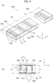
- FIGs. 4(a) and 4(b) are views illustrating the fin structure 0A as a first configuration example of the fin structure 60.
- FIG. 4(a) is a perspective view of the first configuration example
- FIG. 4(b) is a cross-sectional view in a plane IVB shown in FIG. 4(a) .
- the fin structure 60A is formed of a square tube 64 having a height h1, a width w1 and a depth d1.
- the square tube 64 has an upper surface 64U and a lower surface 64L that are spaced apart in the Y direction by the height h1.
- the square tube 64 has two side surfaces 64S and 64S that are spaced apart in the X direction by the width w1. These two side surfaces 64S and 64S constitute the pair of strips 63 and 63 described above, and the upper surface 64U and the lower surface 64L function as linking members between the side surfaces 64S and 64S.
- the upper surface 64U and the lower surface 64L are cut and bent toward the inside of the square tube 64 to form multiple fins 61. That is, the multiple fins 61 are bent from the upper surface 64U or the lower surface 64L to be perpendicular to the Z direction while being supported by the upper surface 64U or the lower surface 64L. Note that a height h2 of the fin 61 is approximately equal to a length L1 of an exposed portion 65A in the Z direction.
- an exposed portion 65A opens on the upper surface 64U.
- the exposed portion 65A is located behind (or in front of) the fin 61 in the Z direction and exposes the internal space of the square tube 64, through which the fluid 53 flows, to the partition 55. With this exposure, the overall heat transfer coefficient between the fluid 53 and the fluid 54 is improved.
- the fin structure 60A is formed by the lancing process for the square tube 64. That is, the multiple fins 61 are integrally formed with the square tube 64. Since the main processing is only the lancing process, the fin structure 60A can be easily manufactured.
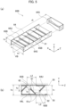
- FIGs. 5(a) and 5(b) are views illustrating a fin structure 60B as a second configuration example of the fin structure 60.
- FIG. 5(a) is a perspective view of the second configuration example
- FIG. 5(b) is a cross-sectional view in a plane VB shown in FIG. 5(a) .
- the difference of the second configuration from the first configuration is that the fins 61 of the fin structure 60B is inclined with respect to the Z direction.
- Other configurations in the second configuration example are the same as those in the first configuration example.
- a height of the fin 61 as seen from the Z direction is set to the height h2 described above. Therefore, by tilting the fin 61 with respect to the Z direction, it is possible to set a length L2 of the exposed portion 65B in the Z direction longer than the length L1. That is, it is possible to increase the opening area of the exposed portion 65B than the opening area of the exposed portion 65A. Therefore, at least the overall heat transfer coefficient in the exposed portion 65B can be improved.
- FIGs. 6(a) and 6(b) are views illustrating a fin structure 60C as a third configuration example of the fin structure 60.
- FIG. 6(a) is a perspective view of the third configuration example
- FIG. 6(b) is a cross-sectional view in a plane VIB shown in FIG. 6(a) .
- the fin 61 of the fin structure 60C as the third configuration example is perpendicular to the Z direction and has an edge 61a formed over the entire range in the X direction. That is, the fin 61 has the height h2 over the entire range in the X direction and forms the opening 62 between the fin 61 and the inner circumferential surface (i.e., the partition 55) of the flow channel 51.
- the fin structure 60C includes the pair of strips 63 and 63. That is, each of the pair of strips 63 and 63 is provided on both sides of the arrangement of the multiple fins 61 in the direction (e.g., the X direction) intersecting the Z direction.
- the pair of strips 63 and 63 connect to both ends of the fins 61 in the X direction and support the fins 61 located between the pair of strips 63 and 63.
- FIGs. 7(a) and 7(b) are views illustrating a fin structure 60D as a fourth configuration example of the fin structure 60.
- FIG. 7(a) is a perspective view of the fourth configuration example
- FIG. 7(b) is a cross-sectional view in a plane VIIB shown in FIG. 7(a) .
- the fin 61 of the fin structure 60D is inclined with respect to the Z direction and has an edge 61a formed over the entire range in the X direction. That is, the fin 61 has the height h2 as seen from the Z direction in the entire X direction and forms an opening 62 between the fin 61 and the inner circumferential surface (i.e., the partition 55) of the flow channel 51.
- the fin structure 60D includes the pair of strips 63 and 63. That is, each of the pair of strips 63 and 63 is provided on both sides of the arrangement of the multiple fins 61 in the direction (e.g., the X direction) intersecting the Z direction.
- the pair of strips 63 and 63 connect to both ends of each fin 61 in the X direction and support the fins 61located between the pair of strips 63 and 63.
- the fin structures 60C and 60D of the third and fourth configuration examples do not have a structure that separates the inner space of the flow channel 51, through which the fluid 53 flows, from the partition 55.
- the partition 55 is exposed to the fluid 53 almost throughout the Z direction. Therefore, it is possible to improve the overall heat transfer coefficient between the fluid 53 and the fluid 54 than that in the first and second configuration examples.
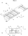
- FIGs. 8(a) and 8(b) are views illustrating a fin structure 60E as a fifth configuration example of the fin structure 60
- FIG. 8(a) is a perspective view of the fifth configuration example
- FIG. 8(b) is a cross-sectional view in a VIIIB shown in FIG. 8(a)
- the fin structure 60E also includes the pair of strips 63 and 63.
- the pair of strips 63 and 63 do not directly support the fins 61. Instead, multiple support portion 66 supports the fins 61.
- the fin structure 60E includes the support portions 66 described above.
- the support portions 66 are provided between the pair of strips 63 and 63 and link the pair of strips 63 and 63.
- the support portion 66 is also connected to the corresponding one of the multiple fins 61.
- the connection between the fin 61 and the support portion 66 constitutes an edge 61a forming the opening 62.
- the support portion 66 is located at the center of the flow channel 51 in the Y direction, for example.
- the multiple fins 61 extend alternately toward one side and the other side in the Y direction from the support portions 66 as the starting points.
- FIGs. 9(a) and 9(b) are views illustrating a fin structure 60F as a sixth configuration example of the fin structure 60.
- FIG. 9(a) is a perspective view of the sixth configuration example
- FIG. 9(b) is a cross-sectional view in a plane IXB shown in FIG. 9(a) .
- the fins 61 of the fin structure 60D are inclined with respect to the Z direction.
- Other configurations are identical to those of the fin structure 60E.
- the fin structures 60E and 60F of the fifth and sixth configuration examples do not have a structure that separates the inner space of the flow channel 51, through which the fluid 53 flows, from the partition 55.
- the partition 55 is exposed to the fluid 53 almost throughout the Z direction. Therefore, it is possible to improve the overall heat transfer coefficient between the fluid 53 and the fluid 54 than that in the first and second configuration examples.
- the connection between the fin 61 and the support portion 66 serves as the fulcrum of the fin 61. Therefore, when the fin structures 60E and 60F are attached to or detached from the flow channel 51, even if the fin 61 contacts with the inner circumferential surface (i.e., the partition 55) of the flow channel 51 (in other words, even if the friction increases), the fin 61 can be bent around the fulcrum. That is, it becomes easier to attach and detach the fin structure.
- the height h2 of the fins 61 can be set as high as possible to suppress leakage between the fin structures 60E and 60F and the inner circumferential surface (i.e., the partition 55) of the flow channel 51 as much as possible.
- the fins 61 may contact the inner circumferential surface (i.e., the partition 55) of the flow channel 51, it is also possible to partially achieve a heat conduction between the fins 61 and the inner circumferential surface (i.e., the partition 55) of the flow channel 51.
- the fin structure 60E of the fifth configuration example and the fin structure 60F of the sixth configuration example are structurally capable of being formed by punching and bending a single plate member without a connecting process such as welding.
- the fins 61 and strip 63 are formed by bending a part of a single plate member that becomes the support portion 66. With the aforementioned formation of such a single plate member, the number of components and the number of the machining processes can be reduced.
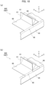
- FIGs. 10(a) and 10(b) are perspective views illustrating a bent portion 68 in the fifth and sixth configuration examples.
- FIG. 10(a) is a view illustrating the first example of the bent portion 68.
- FIG. 10(b) is a view illustrating the second example of the bent portion 68.
- the fin structure 60E and the fin structure 60F can be formed by punching and bending a single plate member. In this case, the strip 63 and the support portion 66 are connected to each other via the bent portion 68 formed by bending the plate member.
- the bent portion 68 may be formed over the entire range in the Z direction as shown in FIG. 10(a) . Otherwise, it may be formed only at a position between the strip 63 and the support portion 66 in the Z direction as shown in FIG. 10(b) .
- the former is easier to process than the latter.
- the latter makes it easier than the former to keep the width of the fin 61 constant across the Y direction and to reduce the leakage from between the fin 61 and the flow channel 51.
- the dash-dotted line in FIG. 10(b) illustrates part of the outlines of the fin 61 and the bent portion 68 shown in FIG. 10(a) .
- FIGs. 11 and 12 are views illustrating a fin structure 60G as a seventh configuration example of the fin structure 60.
- the fin 61 of the fin structure 60G includes an edge 61a having the height h2 in a partial range in the X direction. In other range, an edge 61c is formed.
- the edges 61c has a height similar to the height h1 of the flow channel 51.
- the edge 61a forms the opening 62 between the edge 61a and the inner circumferential surface (i.e., the partition 55) of flow channel 51.
- the fins 61 are arranged along the Z direction so that the edges 61a are located alternately on one side and the other side of the flow channel 51 in the Y direction.
- the fin structure 60G includes a pair of strips 63 and 63. That is, each of the pair of strips 63 and 63 is provided on both sides of the arrangement of the multiple fins 61 in the direction (e.g., the X direction) intersecting the Z direction.
- the pair of strips 63 and 63 connect to both ends of the fins 61 in the X direction and support the fins 61 located between the pair of strips 63 and 63.
- the fin structure 60G may include multiple connection portions 67 connecting the multiple fins 61.
- the connection portions 67 are supported by the pair of strips 63 and 63.
- the connection portions 67 connect the fins 61 so that the fins 61 meanders in a direction (e.g., X direction) intersecting the Y direction.
- the connection portions 67 and the fins 61 may be integrally formed from a single plate member. That is, the connection portions 67 and the fins 61 may be integrally formed by punching and bending a single pate member formed into a strip. With this integral formation, the number of components and the number of the machining processes can be reduced.
- the fin structure 60 can efficiently transfer heat in the direction in which the fluid meanders. For example, assuming a configuration in which an assembly of parallel flow channels 51 and an assembly of parallel flow channels 52 are stacked to each other, heat moves mainly along the Y direction between fluids 53 and 54. Therefore, heat exchange can be improved by using the fin structure 60.
- the reactor (catalytic reactor) described below is designed with taking into consideration this point.
- the reactor 1 includes a heat exchange section 2 as the heat exchange structure 50.
- first heat transfer bodies 10 and second heat transfer bodies 20 are stacked in the Y direction, and first flow channels (channels) 11 and second flow channels (channels) 21 extend in the Z direction.
- the width direction of each channel is taken as the X direction described above.
- the X direction is also the alignment direction when multiple first flow channels 11 (second flow channels 21) are provided in parallel.
- FIG. 13 is a side view illustrating the reactor (catalytic reactor) 1 including the heat exchange structure 50 according to the present embodiment.
- FIG. 14 is a cross-sectional view taken along the line XIV-XIV in FIG. 13 .
- FIG. 15 is a cross-sectional view taken along the line XV-XV in FIG. 13 .
- FIG. 16 is a three-dimensional view with a cross section illustrating a part of the heat exchange section 2 as the heat exchange structure 50.
- the reactor 1 heats or cools the reaction fluid R containing a reactive raw material to progress (promote) the reaction of the reaction fluid R.
- the reactor 1 includes the heat exchange section 2 as the heat exchange structure 50 (see FIGs. 1(a) and 1(b) ) that exchanges (transfers) heat between the heat medium M and the reaction fluid R.
- the heat exchange section 2 includes the first heat transfer bodies 10, the second heat transfer bodies 20, and a lid plate 30.
- the first heat transfer body 10, the second heat transfer body 20 and the lid plate 30 are flat plate members formed of heat-resistant and thermally conductive materials. They have sufficient thickness to withstand a high internal pressure generated while the reaction fluid R flows.
- the first heat transfer body 10 includes channels (hereafter referred to as first channels) 11 through which the heat medium M flows.
- the second heat transfer body 20 includes channels (hereafter referred to as second channels) 21 through which the reaction fluid R flows.
- the first heat transfer bodies 10 and the second heat transfer bodies 20 are stacked alternately in the Y direction (i.e., the stacking direction).
- the lid plate 30 is set on the top of them.
- the first flow channels 11 and the second flow channels 21 are adjacent to each other thorough a first partition 13 or a second partition 23 (see FIG. 16 ).
- the first flow channels 11 and the second flow channels 21 are stacked in a non-contact state in the stacking direction of the first heat transfer bodies 10 and the second heat transfer bodies 20.
- the first heat transfer body 10 and the second heat transfer body 20 are formed of a thermally conductive material. Therefore, the first flow channel 11 and the second flow channel 21 are thermally coupled to each other.
- the heat exchange section 2 has a counter-flow type structure in which the reaction fluid R and the heat medium M flow in opposite directions.
- the fin structure 60 (see FIGs. 1(a) to 12 ) is detachably installed in the first flow channels 11, the second flow channels 21, or both.
- the fin structure 60 on which a catalyst is supported may be detachably installed in the second flow channel 21 through which the reaction fluid R flows.
- the heat exchange section 2 is formed of at least one set of the first heat transfer body 10 and the second heat transfer body 20.
- the number of each heat transfer body may also be increased to improve the heat exchange performance.
- the number of channels formed in each heat transfer body is set depending on the design conditions of the heat exchange section 2, heat transfer efficiency, etc.
- a housing or insulation material may cover the heat exchange section 2 to reduce heat loss due to heat dissipation from the heat exchange section 2.
- Both ends of the heat exchange section 2, which is a laminated body, are held by fixing members 32, 33.
- a heat medium introduction section 34 is attached to the fixing member 32.
- the heat medium introduction section 34 is a concavely curved lid and forms a space S1 between the section 34 and the heat exchange section 2.
- First inlet ports 12 of the first flow channels 11 are opened toward the space S1 (see FIG. 14 ).
- the first inlet ports 12 are opened on the side surface (end face) 2a of the heat exchange section 2 facing the heat medium introduction section 34.
- the heat medium introduction section 34 has a first introduction tube 36 to introduce the heat medium M.
- the heat medium M flows into each first flow channel 11 through the first introduction tube 36.
- the heat medium introduction section 34 is detachably or openably set on the fixing member 32. By this attachment and detachment, for example, the operator can insert and remove the fin structures 60 from the first flow channels 11.
- the heat medium discharge section 41 is a box-shaped member having one opened face.
- the heat medium discharge section 41 is attached to the heat exchange section 2 so that the opened face faces the first discharge ports 18 of the first heat transfer bodies 10.
- the heat medium discharge section 41 includes a first discharge pipe 42.
- the first discharge pipe 42 discharges the heat medium M that has passed through the heat exchange section 2.
- a reaction fluid introduction section 35 is attached to the fixing member 33.
- the reaction fluid introduction section 35 is a concavely curved lid and forms a space S2 between the section 35 and the heat exchange section 2.
- Second inlet ports 22 of the second flow channels 21 are opened toward the space S2 (see FIG. 15 ).
- the second inlet ports 22 are opened on the side surface (end face) 2b of the heat exchange section 2 facing the reaction fluid introduction section 35.
- the reaction fluid introduction section 35 has a second introduction tube 37 to introduce the reaction fluid R. The reaction fluid R flows into each second flow channel 21 through the second introduction tube 37.
- the reaction fluid introduction section 35 is detachably or openably set on the fixing member 33. By this attachment and detachment, for example, the operator can insert and remove the fin structures 60 from the second flow channels 21.
- the product discharge section 43 is a box-shaped member having one opened face.
- the product discharge section 43 is attached to the heat exchange section 2 so that the opened face faces the second discharge port 28 of the second heat transfer body 20.
- the product discharge section 43 includes a second discharge pipe 44.
- the second discharge pipe 44 discharges the reaction gas G containing products derived from the reaction fluid R.
- the first heat transfer body 10 includes multiple first flow channels 11.
- the first flow channels 11 extend in the Z direction and are arranged in the X direction (the width direction) .
- the first flow channels 11 supply the heat of the heat medium M to the first heat transfer body 10.
- the first flow channels 11 are grooves formed on one surface (e.g., the upper surface in the present embodiment) of the first heat transfer body 10.
- Each groove has a rectangular cross section having a width w3 and a height h3 (see FIG. 16 ) and extends in one direction with a length of a depth d3 (see FIG. 15 ).
- the width w3 has a value greater than or equal to the width w1 of the fin structure 60.
- the height h3 also has a value greater than or equal to the height h1 of the fin structure 60.
- the depth d3 is greater than the depth d1 of the fin structure 60.
- the first flow channels 11 linearly extend from the first inlet port 12 located on the side of the fixing member 32 toward the fixing member 33. As shown in FIG. 14 , the multiple first flow channels 11 are arranged in parallel. The first flow channels 11 may be different in the width, height and length.
- the first heat transfer body 10 includes a first partition 13, two first sidewalls 14, multiple first intermediate walls 15, and a first end wall 16.
- the first sidewall 14, the first intermediate walls 15 and the first end wall 16 are provided on one side of the first partition 13. That is, they are provided on the same surface as the surface on which the first sidewall 14, etc. is provided for the first partition 13.
- the first partition 13 is a rectangular wall and defines the overall shape of the first heat transfer body 10.
- the first sidewalls 14 are wall parts provided on both sides of the extending direction of the first flow channels 11.
- the first intermediate walls 15 are located between the two first sidewalls 14 and are wall parts provided in parallel with each first sidewall 14.
- the first end wall 16 is provided on the opposite side of the first inlet ports 12 across the first flow channels 11.
- the first end wall 16 is a wall extending in the alignment direction of the first flow channels 11. The first end wall 16 blocks the inflow of the heat medium M toward the space S2.
- the first heat transfer body 10 includes a first connection flow channel 17 extending along the first end wall 16.
- the first connection flow channel 17 is connected with all the first flow channels 11 and the first discharge port 18.
- the second heat transfer body 20 includes multiple second flow channels 21 including reaction regions.
- the middle section of the second flow channel 21 is the main reaction region.
- the second flow channels 21 extend in the Z direction and are arranged in the X direction (the width direction).
- the second flow channel 21 receives the heat of the heat medium M flowing through the first flow channel 11 in the first heat transfer body 10 to react the reaction fluid R to produce the reaction gas G containing the products derived from the reaction fluid R.
- the second flow channels 21 are grooves formed on one surface (the upper surface in the present embodiment) of the second heat transfer body 20. Each groove has a rectangular cross section having a width w3 and a height h3 (see FIG. 16 ) and extends in one direction with a length of a depth d3 (see FIG. 15 ).
- the second flow channels 21 linearly extend from the second inlet port 22 located on the side of the fixing member 33 toward the fixing member 32. As shown in FIG. 15 , the multiple second flow channels 21 are arranged in parallel.
- the second heat transfer body 20 includes a second partition 23, two second sidewalls 24, multiple second intermediate walls 25, and a second end wall 26.
- the second sidewall 24, the second intermediate walls 25 and the second end wall 26 are provided on one side of the second partition 23.
- the second partition 23 is a rectangular wall and defines the overall shape of the second heat transfer body 20.
- the second sidewalls 24 are wall parts provided on both sides of the extending direction of the second flow channels 21.
- the second intermediate walls 25 are located between the two second sidewalls 24 and are wall parts provided in parallel with each second sidewall 24.
- the second end wall 26 is provided on the opposite side of the second inlet ports 22 across the second flow channel 21.
- the second end wall 26 is a wall extending in the alignment direction of the second flow channels 21.
- the second end wall 26 blocks the inflow of the reaction gas G toward the space S1.
- the second heat transfer body 20 includes a second connection flow channel 27 extending along the second end wall 26.
- the second connection flow channel 27 is connected with all the second flow channels 21 and the second discharge port 28.
- the second connection flow channel 27 is a fluid channel, and there is no substantial difference between the two.
- the heat exchange section 2 can be used as any of a liquid-liquid heat exchanger, a gas-gas heat exchanger and a gas-liquid heat exchanger.
- the reaction fluid R may be any of a gas and a liquid.
- the heat medium M may be any of a gas and a liquid.
- the reactor 1 of the present embodiment enables chemical synthesis through various thermal reactions such as endothermic and exothermic reactions. Examples of such syntheses by thermal reactions include endothermic reactions such as the steam reforming reaction of methane represented by formula (3), the dry reforming reaction of methane represented by formula (4), the shift reaction represented by formula (5), the methanation reaction represented by formula (6), and the Fischer Tropsch synthesis reaction represented by formula (7).
- reaction fluid R in these reactions is a gas.
- the heat medium M is a substance that does not corrode the components of the reactor 1.
- gaseous materials such as a combustion gas and a heated air can be used.
- the heat medium M may be a liquid substance such as water or oil, for example.
Landscapes
- Engineering & Computer Science (AREA)
- Physics & Mathematics (AREA)
- Mechanical Engineering (AREA)
- Thermal Sciences (AREA)
- General Engineering & Computer Science (AREA)
- Chemical & Material Sciences (AREA)
- Chemical Kinetics & Catalysis (AREA)
- Organic Chemistry (AREA)
- Geometry (AREA)
- Heat-Exchange Devices With Radiators And Conduit Assemblies (AREA)
- Cooling Or The Like Of Semiconductors Or Solid State Devices (AREA)
- Cooling Or The Like Of Electrical Apparatus (AREA)
- Physical Or Chemical Processes And Apparatus (AREA)
Abstract
Description
- The present disclosure relates to a heat exchange structure that performs a heat exchange between two fluids.
- The heat-exchange catalytic reactor includes a heat-exchange structure that performs a heat exchange between two fluids. The heat exchange structure includes a heat medium flow channel and a reaction flow channel, which are adjacent to each other. A heat medium flows in the heat medium flow channel. A reaction fluid, which contains a reactive raw material, flows in the reaction flow channel. The heat medium flow channel and the reaction flow channel are thermally coupled to each other through a partition. Therefore, the heat exchange occurs between the heat medium and the reaction fluid between which there is a temperature difference, and the reaction of the reactive raw material is promoted.
- A fin structure may be installed in at least one of the heat medium flow channel and the reaction flow channel to improve the overall heat transfer coefficient between the heat medium and the reaction fluid. The fin structure is called corrugated fins or waving fins. It is formed, for example, by bending a metal plate. The fin structure has a number of fins (side surfaces) that are stretched or curved in the longitudinal direction of the channel in which the fin structure is installed. In this regard, Patent Literature 1 (PTL 1) discloses a heat transfer promoter as the fin structure. When the aforementioned fin structure is installed in the reaction flow channel, the catalyst may be supported on the fin structure.
- [PTL 1]
JP 2017-140591 A - Conventional fin structures deflect or disperse fluid along a surface on which the fins are placed. Therefore, when such a fin structure is installed in the heat exchange structure described above, the fluid generally flows along the partition. On the other hand, heat to be exchanged between the heat medium and the reaction fluid is transferred through this partition. The heat flux is proportional to the temperature difference (temperature gradient). Therefore, the heat transfer between the fluids is larger closer to the partition where the temperature boundary layer is generated, and is smaller farther from the partition. Accordingly, the farther the fluid is from the partition, the less likely it is to be heated (or cooled). This situation hinders the improvement of the heat transfer rate. In order to sufficiently heat (cool) the fluid everywhere, it can be dealt with by lengthening the flow path of the fluid. In this case, however, the equipment becomes larger, and the manufacturing cost increases.
- The present disclosure has been made to provide a heat exchange structure capable of improving the overall heat transfer coefficient between two fluids in a space with a limited length.
- An aspect of the present disclosure is a heat exchange structure including: two channels stacked in a stacking direction and thermally coupled to each other; and a fin structure detachably installed in at least one flow channel of the two flow channels, wherein the fin structure includes fins arranged in a longitudinal direction of the at least one flow channel in which the fin structure is installed, the fins configured to form openings alternately arranged along the at least one flow channel on one side and the other side of the at least one flow channel in the stacking direction.
- The fins may be perpendicular to the longitudinal direction of the at least one flow channel in which the fin structure is installed. The fins may be inclined with respect to the longitudinal direction of the at least one flow channel in which the fin structure is installed. Some of the fins may be arranged at a different pitch from the other of the fins. The fin structure may include a pair of strips configured to support the fins, provided on both sides of the arrangement of the fins in a direction intersecting the stacking direction.
- The fin structure may include: a pair of strips provided on both sides of the arrangement of the fins in a direction intersecting the stacking direction; and support portions configured to link the pair of strips, provided between the pair of strips, and connected to a corresponding one of the fins. The fin structure may be integrally formed of a single plate member.
- The fin structure may include connection portions supported by the pair of strips, configured to connect the fins so that the fins meanders in a direction intersecting the stacking direction. The fins and the connection portions may be integrally formed of a single plate member. A catalyst may be supported on the fin structure.
- According to the present disclosure, it is possible to provide a heat exchange structure capable of improving the overall heat transfer coefficient between two fluids in a space with a limited length.
-
-
FIGs. 1(a) and 1(b) are views illustrating a basic configuration of a heat exchange structure according to the present disclosure.FIG. 1(a) is the view illustrating a cross section of the heat exchange structure in a Y-Z plane.FIG. 1(b) is a cross section along the line IB-IB shown inFIG. 1(a) . -
FIG. 2 is a view illustrating a modification of the basic configuration of the heat exchange structure. -
FIGs. 3(a) to 3(c) are views illustrating examples of fin arrangements according to the present disclosure. -
FIGs. 4(a) and 4(b) are views illustrating a first configuration example of the fin structure according to the present disclosure.FIG. 4(a) is a perspective view of the first configuration example, andFIG. 4(b) is a cross-sectional view in a plane IVB shown inFIG. 4(a) . -
FIGs. 5(a) and 5(b) are views illustrating a first configuration example of the fin structure according to the present disclosure.FIG. 5(a) is a perspective view of the first configuration example, andFIG. 5(b) is a cross-sectional view in a plane VB shown inFIG. 5(a) . -
FIGs. 6(a) and 6(b) are views illustrating a first configuration example of the fin structure according to the present disclosure.FIG. 6(a) is a perspective view of the first configuration example, andFIG. 6(b) is a cross-sectional view in a plane VIB shown inFIG. 6(a) . -
FIGs. 7(a) and 7(b) are views illustrating a first configuration example of the fin structure according to the present disclosure.FIG. 7(a) is a perspective view of the first configuration example, andFIG. 7(b) is a cross-sectional view in a plane VIIB shown inFIG. 7(a) . -
FIGs. 8(a) and 8(b) are views illustrating a first configuration example of the fin structure according to the present disclosure.FIG. 8(a) is a perspective view of the first configuration example, andFIG. 8(b) is a cross-sectional view in a plane VIIIB shown inFIG. 8(a) . -
FIGs. 9(a) and 9(b) are views illustrating a first configuration example of the fin structure according to the present disclosure.FIG. 9(a) is a perspective view of the first configuration example, andFIG. 9(b) is a cross-sectional view in a plane IXB shown inFIG. 9(a) . -
FIGs. 10(a) and 10(b) are perspective views illustrating a bent portion in the fifth and sixth configuration examples.FIG. 10(a) is a perspective view of the first example of the bent portion, andFIG. 10(b) is a perspective view of the second example of the bent portion. -
FIG. 11 is a view illustrating a seventh configuration example of the fin structure according to the present disclosure. -
FIG. 12 is a view illustrating a seventh configuration example of the fin structure according to the present disclosure. -
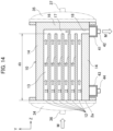
FIG. 13 is a side view illustrating a reactor including the heat exchange structure according to the present embodiment. -
FIG. 14 is a cross-sectional view along the line XIV-XIV inFIG. 13 . -
FIG. 15 is a cross-sectional view along the XV-XV line inFIG. 13 . -
FIG. 16 is a three-dimensional view with a cross section illustrating a part of the heat exchange section according to the present embodiment. - Embodiments according to the present disclosure are described below with reference to the drawings. In the drawings, common parts are denoted by the same symbols and redundant explanations thereof will be omitted.
- A basic configuration of a
heat exchange structure 50 according to the present embodiment will be described. Hereafter, for convenience of explanation, X, Y and Z directions are defined as three directions perpendicular to each other. As described later, the Y direction is a stacking direction of twoflow channels -
FIGs. 1(a) and 1(b) are views illustrating a basic configuration of aheat exchange structure 50 according to the present embodiment.FIG. 1(a) is the view illustrating a cross section of theheat exchange structure 50 in the Y-Z plane.FIG. 1(b) is a cross section along the line IB-IB shown inFIG. 1(a) .FIG. 2 is a view illustrating a modification of the basic configuration of theheat exchange structure 50. - As shown in
FIG. 1(a) , theheat exchange structure 50 includes at least oneflow channel 51 and at least oneflow channel 52. Theflow channels flow channels flow channel 51 and theflow channel 52 are provided parallel and thermally connected to each other through apartition 55. Theflow channel 51 is applied as one of afirst flow channel 11 and asecond flow channel 21 described later, and theflow channel 52 is applied as the other of thefirst flow channel 11 and thesecond flow channel 21. Thepartition 55 between theflow channel 51 and theflow channel 52 corresponds to afirst partition 13 or asecond partition 23, which will be described later. - The
heat exchange structure 50 may be provided withmultiple flow channels 51 andmultiple flow channels 52. For example, theflow channels 51 are parallel to each other on a plane parallel to the X-Z plane, and theflow channels 52 are parallel to each other on the plane parallel to the X-Z plane. The longitudinal directions of theflow channel 51 and theflow channel 52 may be parallel to each other or may intersect with each other. That is, the latter may have a skewed relationship. In both cases, one of theflow channels flow channels partition 55 in most of the sections in the longitudinal directions of the channels. - As shown in
FIG. 1(a) ,fluid 53 flows in theflow channel 51 andfluid 54 flows in theflow channel 52. The fluid 53 is one of a heat medium M and the reaction fluid R described later. The fluid 54 is the other of the heat medium M and the reaction fluid R. The flow of the fluid 53 and the fluid 54 may be countercurrent or parallel (cocurrent). - There is a temperature difference ΔT, between
fluid 53 andfluid 54. Therefore, when fluid 53 flows throughflow channel 51 andfluid 54 flows throughflow channel 52, heat is transferred between the fluid 53 and the fluid 54. Specifically, the heat is transferred between the fluid 53 and the fluid 54 due to convection between the fluid 53 and thepartition 55, thermal conduction within thepartition 55, and convection between thepartition 55 and the fluid 54. - In this case, the amount of heat Q per unit time is proportional to the product of the overall heat transfer coefficient (heat transfer rate) U, the heat transfer area A of the
partition 55, and the temperature difference ΔT between the fluid 53 and the fluid 54. That is, the relationship among these values is expressed by the following formula (1):
- Here, the heat transfer area A is constant. Since the fluid 53 and the fluid 54 flow steadily, the change in the temperature difference ΔT is small. Therefore, it is found that the increase in amount of heat Q is obtained by increasing the overall heat transfer coefficient U.
- There is also the following relationship among the overall heat transfer coefficient U, the heat transfer coefficient H1 between the fluid 53 and the
partition 55, the heat transfer coefficient H2 between thepartition 55 and the fluid 54, and the thermal conductivity K of thepartition 55.
partition 55. - From the formula (2), it is found that the overall heat transfer coefficient U increases when at least one of the heat transfer coefficients H1 and H2 increases.
- The heat transfer coefficient H1 increases by accelerating the fluid 53 near the
partition 55. This trend is the same for the heat transfer coefficient H2. In the present embodiment, using afin structure 60, a main flow of at least one of thefluids partition 55. This allows a portion of the main flow to approach or enter the temperature boundary layer near thepartition 55, thereby promoting the heat transfer between the main flow and thepartition 55. That is, at least one of the heat transfer coefficient H1 and the heat transfer coefficient H2 increases. As a result, the overall heat transfer coefficient U increases, and eventually the amount of heat Q increases. That is, the overall heat transfer coefficient between two fluids can be improved in a space with a limited length. - The
fin structure 60 according to the present embodiment is detachably installed in at least one of theflow channels fin structure 60 is described below using an example shown inFIG. 1(a) and FIG. 1(b) . That is, thefin structure 60 is installed in theflow channel 51, but it is not installed in theflow channel 52. - As shown in
FIG. 1(b) , thefin structure 60 has a width w1 in the X direction and a height h1 in the Y direction. The width w1 of thefin structure 60 is set to a value approximately equal to the width w3 of theflow channel 51. Also, the height h1 of thefin structure 60 is set to a value less than or equal to a height h3 of theflow channel 51. The width w1 is set to a value that minimizes leakage between the inner and outer surfaces of theflow channel 51. The height h1 may be set to such a value that a clearance for preventing stagnation of the fluid 53 is formed. The depth d1 of thefin structure 60 is appropriately set according to the dimensions of theflow channel 51 and the usage condition thereof. For example, depth d1 is set to a value less than or equal to depth d3 offlow channel 51. - The
fin structure 60 includes multiple fins (deflection plates, partition plates) 61. Thefin 61 is a substantially rectangular piece of a thin metal plate. The metal plate faces in the Z direction and extends in the X direction. The pitch (interval) P between the twofins fins 61 may be arranged at a different pitch P from the other of thefins 61. By varying the pitch P, it is possible to vary the local overall heat transfer coefficient along the Z direction. - As shown in
FIG. 1(b) , thefin 61 has anedge 61a which extends in the X direction. At theedge 61a, thefin 61 has a height h2 in the Y direction. The height h2 is set to a value less than the height h3 of theflow channel 51 and greater than or equal to a half of the height h3. The difference between the height h3 of theflow channel 51 and the height h2 of thefin 61 forms anopening 62 inside theflow channel 51. That is, thefins 61 form theopenings 62 between theedges 61a and the inner circumferential surface (i.e., the partition 55) of theflow channel 51. As described later, the fluid 53 flows in theflow channel 51 through theopenings 62. - As shown in
FIG. 1(b) , theedge 61a may be formed over the entire range in the X direction. Otherwise, theedge 61a may be formed in a partial range in the X direction (seeFIGs. 10(a) and 10(b) ). In the former case, thefins 61 are alternately arranged along the Z direction on one side and the other side of theflow channel 51 in the Y direction. In the latter case, thefins 61 are arranged along the Z direction so that the positions of theedges 61a are alternately located along the Z direction on one side and the other side of theflow channel 51 in the Y direction. - As shown in
FIG. 1(a) , thefins 61 may be perpendicular to the longitudinal direction (i.e., the Z direction) of theflow channel 51. Alternatively, as shown inFIG. 2 , thefin 61 may be inclined with respect to the longitudinal direction of theflow channel 51. In the latter case, thefin 61 may be inclined so that theedge 61a forming theopening 62 is located upstream of theflow channel 51 from theopposite edge 61b, or vice versa. -
FIGs. 3(a) to 3(c) are views illustrating examples of arrangements of thefins 61. As shown in these figures, thefin 61 may be inclined with respect to the X direction. When thefin 61 is inclined with respect to the X direction, thefin 61 may be perpendicular to the longitudinal direction of theflow channel 51 as shown inFIG. 3(a) or inclined with respect to the longitudinal direction of theflow channel 51 as shown inFIG. 3 (b) and FIG. 3 (c) . In addition, theflow channel 51 may include a mixture of the perpendicular orinclined fins 61 described above. - The
fin structure 60 includes a pair ofstrips strips multiple fins 61 in the direction intersecting the Z direction (e.g., the X direction). The pair ofstrips multiple fins 61 located between them. However, thefins 61 may be supported by a member linking the pair ofstrips 63 and 63 (e.g., asupport portion 66 shown inFIG. 8(a) ) or a member having the pair ofstrips square tube 64 shown inFIG. 4(a) ). - As described above, the
openings 62 open toward the Z direction (longitudinal direction) of theflow channel 51 and are alternately arranged along theflow channel 51 on one side and the other side of theflow channel 51 in the Y direction (stacking direction). That is, theopenings 62 are arranged zigzag along the Z direction so as to reciprocate in the Y direction. Therefore, the fluid 53 flows in the Z direction while repeating the reciprocation in the Y direction. In other words, the fluid 53 flows in the Z direction with meandering in the Y direction. - The
fin structure 60 has no structure interfering with heat transfer at least in part between the path of the meanderingfluid 53 and thepartition 55. In other words, thefin structure 60 has a portion (i.e., an opening) which exposes the fluid 53 to thepartition 55 in each interval in which the fluid 53 reciprocates in the Y direction. Therefore, part of the fluid 53 can directly approach or enter the temperature boundary layer TB near thepartition 55. Accordingly, it is possible to increase the heat transfer coefficient H1 and to improve the heat transfer coefficient between the fluid 53 and the fluid 54. For example, if the temperature of the fluid 53 is higher than the temperature of the fluid 54, the heat flow HF shown inFIG. 1(b) can be promoted. - A similar improvement in overall heat transfer coefficient can also be obtained by placing the
fin structure 60 in theflow channel 52. That is, the heat transfer coefficient H2 can be increased by installing thefin structure 60 in theflow channel 52. Further, by installing afin structure 60 in each of theflow channels fin structure 60 in a space with a limited length. - The
fin structure 60 is formed of a heat-resistant material that can support a catalyst. Such materials include heat-resistant alloys mainly composed of one or more kinds of metals such as Fe (iron), Cr (chromium), Al (aluminum), Y (yttrium), Co (cobalt), Ni (nickel), Mg (magnesium), Ti (titanium), Mo (molybdenum), W (tungsten), Nb (niobium), and Ta (tantalum). For example, thefin structure 60 may be formed by molding a thin-plate structural material made of a heat-resistant alloy such as Fecralloy (R) or the like. - When a catalyst is supported on the
fin structure 60, the catalyst contains as a main component an active metal effective for promoting the progress of chemical reactions. The active metal is, for example, Ni (nickel), Co (cobalt), Fe (iron), Pt (platinum), Ru (ruthenium), Rh (rhodium), Pd (palladium). Only one of these metals may be used, or a combination of several of these metals may be used as long as they are effective in promoting the reaction. - Next, a configuration example of the
fin structure 60 will be described.FIGs. 4(a) and 4(b) are views illustrating the fin structure 0A as a first configuration example of thefin structure 60.FIG. 4(a) is a perspective view of the first configuration example, andFIG. 4(b) is a cross-sectional view in a plane IVB shown inFIG. 4(a) . - As shown in
FIG. 4(a) , thefin structure 60A is formed of asquare tube 64 having a height h1, a width w1 and a depth d1. Thesquare tube 64 has anupper surface 64U and alower surface 64L that are spaced apart in the Y direction by the height h1. Thesquare tube 64 has twoside surfaces side surfaces strips upper surface 64U and thelower surface 64L function as linking members between the side surfaces 64S and 64S. - The
upper surface 64U and thelower surface 64L are cut and bent toward the inside of thesquare tube 64 to formmultiple fins 61. That is, themultiple fins 61 are bent from theupper surface 64U or thelower surface 64L to be perpendicular to the Z direction while being supported by theupper surface 64U or thelower surface 64L. Note that a height h2 of thefin 61 is approximately equal to a length L1 of an exposedportion 65A in the Z direction. - As a result of the lancing process described above, an exposed
portion 65A opens on theupper surface 64U. The exposedportion 65A is located behind (or in front of) thefin 61 in the Z direction and exposes the internal space of thesquare tube 64, through which the fluid 53 flows, to thepartition 55. With this exposure, the overall heat transfer coefficient between the fluid 53 and the fluid 54 is improved. - The
fin structure 60A is formed by the lancing process for thesquare tube 64. That is, themultiple fins 61 are integrally formed with thesquare tube 64. Since the main processing is only the lancing process, thefin structure 60A can be easily manufactured. -
FIGs. 5(a) and 5(b) are views illustrating afin structure 60B as a second configuration example of thefin structure 60.FIG. 5(a) is a perspective view of the second configuration example, andFIG. 5(b) is a cross-sectional view in a plane VB shown inFIG. 5(a) . The difference of the second configuration from the first configuration is that thefins 61 of thefin structure 60B is inclined with respect to the Z direction. Other configurations in the second configuration example are the same as those in the first configuration example. - A height of the
fin 61 as seen from the Z direction is set to the height h2 described above. Therefore, by tilting thefin 61 with respect to the Z direction, it is possible to set a length L2 of the exposedportion 65B in the Z direction longer than the length L1. That is, it is possible to increase the opening area of the exposedportion 65B than the opening area of the exposedportion 65A. Therefore, at least the overall heat transfer coefficient in the exposedportion 65B can be improved. -
FIGs. 6(a) and 6(b) are views illustrating afin structure 60C as a third configuration example of thefin structure 60.FIG. 6(a) is a perspective view of the third configuration example, andFIG. 6(b) is a cross-sectional view in a plane VIB shown inFIG. 6(a) . Thefin 61 of thefin structure 60C as the third configuration example is perpendicular to the Z direction and has anedge 61a formed over the entire range in the X direction. That is, thefin 61 has the height h2 over the entire range in the X direction and forms theopening 62 between thefin 61 and the inner circumferential surface (i.e., the partition 55) of theflow channel 51. - The
fin structure 60C includes the pair ofstrips strips multiple fins 61 in the direction (e.g., the X direction) intersecting the Z direction. The pair ofstrips fins 61 in the X direction and support thefins 61 located between the pair ofstrips -
FIGs. 7(a) and 7(b) are views illustrating afin structure 60D as a fourth configuration example of thefin structure 60.FIG. 7(a) is a perspective view of the fourth configuration example, andFIG. 7(b) is a cross-sectional view in a plane VIIB shown inFIG. 7(a) . Thefin 61 of thefin structure 60D is inclined with respect to the Z direction and has anedge 61a formed over the entire range in the X direction. That is, thefin 61 has the height h2 as seen from the Z direction in the entire X direction and forms anopening 62 between thefin 61 and the inner circumferential surface (i.e., the partition 55) of theflow channel 51. - As same as the third configuration, the
fin structure 60D includes the pair ofstrips strips multiple fins 61 in the direction (e.g., the X direction) intersecting the Z direction. The pair ofstrips fin 61 in the X direction and support the fins 61located between the pair ofstrips - The
fin structures flow channel 51, through which the fluid 53 flows, from thepartition 55. Thus, thepartition 55 is exposed to the fluid 53 almost throughout the Z direction. Therefore, it is possible to improve the overall heat transfer coefficient between the fluid 53 and the fluid 54 than that in the first and second configuration examples. -
FIGs. 8(a) and 8(b) are views illustrating afin structure 60E as a fifth configuration example of thefin structure 60,FIG. 8(a) is a perspective view of the fifth configuration example, andFIG. 8(b) is a cross-sectional view in a VIIIB shown inFIG. 8(a) . As same as the configuration examples described above, thefin structure 60E also includes the pair ofstrips strips fins 61. Instead,multiple support portion 66 supports thefins 61. - The
fin structure 60E includes thesupport portions 66 described above. Thesupport portions 66 are provided between the pair ofstrips strips support portion 66 is also connected to the corresponding one of themultiple fins 61. The connection between thefin 61 and thesupport portion 66 constitutes anedge 61a forming theopening 62. - As shown in
FIG. 8(b) , thesupport portion 66 is located at the center of theflow channel 51 in the Y direction, for example. Themultiple fins 61 extend alternately toward one side and the other side in the Y direction from thesupport portions 66 as the starting points. -
FIGs. 9(a) and 9(b) are views illustrating afin structure 60F as a sixth configuration example of thefin structure 60.FIG. 9(a) is a perspective view of the sixth configuration example, andFIG. 9(b) is a cross-sectional view in a plane IXB shown inFIG. 9(a) . Thefins 61 of thefin structure 60D are inclined with respect to the Z direction. Other configurations are identical to those of thefin structure 60E. - As similar to the third and fourth configuration examples, the
fin structures flow channel 51, through which the fluid 53 flows, from thepartition 55. Thus, thepartition 55 is exposed to the fluid 53 almost throughout the Z direction. Therefore, it is possible to improve the overall heat transfer coefficient between the fluid 53 and the fluid 54 than that in the first and second configuration examples. - In the
fin structures fin 61 and thesupport portion 66 serves as the fulcrum of thefin 61. Therefore, when thefin structures flow channel 51, even if thefin 61 contacts with the inner circumferential surface (i.e., the partition 55) of the flow channel 51 (in other words, even if the friction increases), thefin 61 can be bent around the fulcrum. That is, it becomes easier to attach and detach the fin structure. - In addition, since the
fins 61 can be bent during the attachment and the detachment, the height h2 of thefins 61 can be set as high as possible to suppress leakage between thefin structures flow channel 51 as much as possible. In this case, since thefins 61 may contact the inner circumferential surface (i.e., the partition 55) of theflow channel 51, it is also possible to partially achieve a heat conduction between thefins 61 and the inner circumferential surface (i.e., the partition 55) of theflow channel 51. - The
fin structure 60E of the fifth configuration example and thefin structure 60F of the sixth configuration example are structurally capable of being formed by punching and bending a single plate member without a connecting process such as welding. For example, thefins 61 andstrip 63 are formed by bending a part of a single plate member that becomes thesupport portion 66. With the aforementioned formation of such a single plate member, the number of components and the number of the machining processes can be reduced. -
FIGs. 10(a) and 10(b) are perspective views illustrating abent portion 68 in the fifth and sixth configuration examples.FIG. 10(a) is a view illustrating the first example of thebent portion 68.FIG. 10(b) is a view illustrating the second example of thebent portion 68. As described above, thefin structure 60E and thefin structure 60F can be formed by punching and bending a single plate member. In this case, thestrip 63 and thesupport portion 66 are connected to each other via thebent portion 68 formed by bending the plate member. - The
bent portion 68 may be formed over the entire range in the Z direction as shown inFIG. 10(a) . Otherwise, it may be formed only at a position between thestrip 63 and thesupport portion 66 in the Z direction as shown inFIG. 10(b) . The former is easier to process than the latter. On the other hand, the latter makes it easier than the former to keep the width of thefin 61 constant across the Y direction and to reduce the leakage from between thefin 61 and theflow channel 51. The dash-dotted line inFIG. 10(b) illustrates part of the outlines of thefin 61 and thebent portion 68 shown inFIG. 10(a) . -
FIGs. 11 and12 are views illustrating afin structure 60G as a seventh configuration example of thefin structure 60. Thefin 61 of thefin structure 60G includes anedge 61a having the height h2 in a partial range in the X direction. In other range, anedge 61c is formed. Theedges 61c has a height similar to the height h1 of theflow channel 51. - As same as other configuration examples, the
edge 61a forms theopening 62 between theedge 61a and the inner circumferential surface (i.e., the partition 55) offlow channel 51. As shown inFIG. 11 , thefins 61 are arranged along the Z direction so that theedges 61a are located alternately on one side and the other side of theflow channel 51 in the Y direction. - As shown in
FIG. 11 , thefin structure 60G includes a pair ofstrips strips multiple fins 61 in the direction (e.g., the X direction) intersecting the Z direction. The pair ofstrips fins 61 in the X direction and support thefins 61 located between the pair ofstrips - As shown in
FIG. 12 , thefin structure 60G may includemultiple connection portions 67 connecting themultiple fins 61. Theconnection portions 67 are supported by the pair ofstrips connection portions 67 connect thefins 61 so that thefins 61 meanders in a direction (e.g., X direction) intersecting the Y direction. In this case, theconnection portions 67 and thefins 61 may be integrally formed from a single plate member. That is, theconnection portions 67 and thefins 61 may be integrally formed by punching and bending a single pate member formed into a strip. With this integral formation, the number of components and the number of the machining processes can be reduced. - The
fin structure 60 can efficiently transfer heat in the direction in which the fluid meanders. For example, assuming a configuration in which an assembly ofparallel flow channels 51 and an assembly ofparallel flow channels 52 are stacked to each other, heat moves mainly along the Y direction betweenfluids fin structure 60. The reactor (catalytic reactor) described below is designed with taking into consideration this point. - Hereinafter, a reactor (catalytic reactor) 1 is described as an example to which the
heat exchange structure 50 is applied. The reactor 1 includes aheat exchange section 2 as theheat exchange structure 50. As described later, firstheat transfer bodies 10 and secondheat transfer bodies 20 are stacked in the Y direction, and first flow channels (channels) 11 and second flow channels (channels) 21 extend in the Z direction. In addition, the width direction of each channel is taken as the X direction described above. The X direction is also the alignment direction when multiple first flow channels 11 (second flow channels 21) are provided in parallel. -
FIG. 13 is a side view illustrating the reactor (catalytic reactor) 1 including theheat exchange structure 50 according to the present embodiment.FIG. 14 is a cross-sectional view taken along the line XIV-XIV inFIG. 13 .FIG. 15 is a cross-sectional view taken along the line XV-XV inFIG. 13 .FIG. 16 is a three-dimensional view with a cross section illustrating a part of theheat exchange section 2 as theheat exchange structure 50. - The reactor 1 heats or cools the reaction fluid R containing a reactive raw material to progress (promote) the reaction of the reaction fluid R. For the heating or cooling, the reactor 1 includes the
heat exchange section 2 as the heat exchange structure 50 (seeFIGs. 1(a) and 1(b) ) that exchanges (transfers) heat between the heat medium M and the reaction fluid R. Theheat exchange section 2 includes the firstheat transfer bodies 10, the secondheat transfer bodies 20, and alid plate 30. The firstheat transfer body 10, the secondheat transfer body 20 and thelid plate 30 are flat plate members formed of heat-resistant and thermally conductive materials. They have sufficient thickness to withstand a high internal pressure generated while the reaction fluid R flows. - The first
heat transfer body 10 includes channels (hereafter referred to as first channels) 11 through which the heat medium M flows. The secondheat transfer body 20 includes channels (hereafter referred to as second channels) 21 through which the reaction fluid R flows. The firstheat transfer bodies 10 and the secondheat transfer bodies 20 are stacked alternately in the Y direction (i.e., the stacking direction). Thelid plate 30 is set on the top of them. - With the stacking described above, the
first flow channels 11 and thesecond flow channels 21 are adjacent to each other thorough afirst partition 13 or a second partition 23 (seeFIG. 16 ). In other words, thefirst flow channels 11 and thesecond flow channels 21 are stacked in a non-contact state in the stacking direction of the firstheat transfer bodies 10 and the secondheat transfer bodies 20. As described above, the firstheat transfer body 10 and the secondheat transfer body 20 are formed of a thermally conductive material. Therefore, thefirst flow channel 11 and thesecond flow channel 21 are thermally coupled to each other. - The
heat exchange section 2 has a counter-flow type structure in which the reaction fluid R and the heat medium M flow in opposite directions. The fin structure 60 (seeFIGs. 1(a) to 12 ) is detachably installed in thefirst flow channels 11, thesecond flow channels 21, or both. Thefin structure 60 on which a catalyst is supported may be detachably installed in thesecond flow channel 21 through which the reaction fluid R flows. - The
heat exchange section 2 is formed of at least one set of the firstheat transfer body 10 and the secondheat transfer body 20. The number of each heat transfer body may also be increased to improve the heat exchange performance. The number of channels formed in each heat transfer body is set depending on the design conditions of theheat exchange section 2, heat transfer efficiency, etc. In addition, a housing or insulation material may cover theheat exchange section 2 to reduce heat loss due to heat dissipation from theheat exchange section 2. - Both ends of the
heat exchange section 2, which is a laminated body, are held by fixingmembers - A heat
medium introduction section 34 is attached to the fixingmember 32. The heatmedium introduction section 34 is a concavely curved lid and forms a space S1 between thesection 34 and theheat exchange section 2.First inlet ports 12 of thefirst flow channels 11 are opened toward the space S1 (seeFIG. 14 ). In other words, thefirst inlet ports 12 are opened on the side surface (end face) 2a of theheat exchange section 2 facing the heatmedium introduction section 34. The heatmedium introduction section 34 has afirst introduction tube 36 to introduce the heat medium M. The heat medium M flows into eachfirst flow channel 11 through thefirst introduction tube 36. - The heat
medium introduction section 34 is detachably or openably set on the fixingmember 32. By this attachment and detachment, for example, the operator can insert and remove thefin structures 60 from thefirst flow channels 11. - The heat
medium discharge section 41 is a box-shaped member having one opened face. The heatmedium discharge section 41 is attached to theheat exchange section 2 so that the opened face faces thefirst discharge ports 18 of the firstheat transfer bodies 10. The heatmedium discharge section 41 includes afirst discharge pipe 42. Thefirst discharge pipe 42 discharges the heat medium M that has passed through theheat exchange section 2. - A reaction
fluid introduction section 35 is attached to the fixingmember 33. As similar to the heatmedium introduction section 34, the reactionfluid introduction section 35 is a concavely curved lid and forms a space S2 between thesection 35 and theheat exchange section 2.Second inlet ports 22 of thesecond flow channels 21 are opened toward the space S2 (seeFIG. 15 ).
In other words, thesecond inlet ports 22 are opened on the side surface (end face) 2b of theheat exchange section 2 facing the reactionfluid introduction section 35. The reactionfluid introduction section 35 has asecond introduction tube 37 to introduce the reaction fluid R. The reaction fluid R flows into eachsecond flow channel 21 through thesecond introduction tube 37. - The reaction
fluid introduction section 35 is detachably or openably set on the fixingmember 33. By this attachment and detachment, for example, the operator can insert and remove thefin structures 60 from thesecond flow channels 21. - As similar to the heat
medium discharge section 41, theproduct discharge section 43 is a box-shaped member having one opened face. Theproduct discharge section 43 is attached to theheat exchange section 2 so that the opened face faces thesecond discharge port 28 of the secondheat transfer body 20. Theproduct discharge section 43 includes asecond discharge pipe 44. Thesecond discharge pipe 44 discharges the reaction gas G containing products derived from the reaction fluid R. - As shown in
FIG. 14 , the firstheat transfer body 10 includes multiplefirst flow channels 11. Thefirst flow channels 11 extend in the Z direction and are arranged in the X direction (the width direction) . Thefirst flow channels 11 supply the heat of the heat medium M to the firstheat transfer body 10. - The
first flow channels 11 are grooves formed on one surface (e.g., the upper surface in the present embodiment) of the firstheat transfer body 10. Each groove has a rectangular cross section having a width w3 and a height h3 (seeFIG. 16 ) and extends in one direction with a length of a depth d3 (seeFIG. 15 ). The width w3 has a value greater than or equal to the width w1 of thefin structure 60. Similarly, the height h3 also has a value greater than or equal to the height h1 of thefin structure 60. The depth d3 is greater than the depth d1 of thefin structure 60. - The
first flow channels 11 linearly extend from thefirst inlet port 12 located on the side of the fixingmember 32 toward the fixingmember 33. As shown inFIG. 14 , the multiplefirst flow channels 11 are arranged in parallel. Thefirst flow channels 11 may be different in the width, height and length. - The first
heat transfer body 10 includes afirst partition 13, twofirst sidewalls 14, multiple firstintermediate walls 15, and afirst end wall 16. thefirst sidewall 14, the firstintermediate walls 15 and thefirst end wall 16 are provided on one side of thefirst partition 13. That is, they are provided on the same surface as the surface on which thefirst sidewall 14, etc. is provided for thefirst partition 13. Thefirst partition 13 is a rectangular wall and defines the overall shape of the firstheat transfer body 10. Thefirst sidewalls 14 are wall parts provided on both sides of the extending direction of thefirst flow channels 11. The firstintermediate walls 15 are located between the twofirst sidewalls 14 and are wall parts provided in parallel with eachfirst sidewall 14. - The
first end wall 16 is provided on the opposite side of thefirst inlet ports 12 across thefirst flow channels 11. Thefirst end wall 16 is a wall extending in the alignment direction of thefirst flow channels 11. Thefirst end wall 16 blocks the inflow of the heat medium M toward the space S2. - The first
heat transfer body 10 includes a first connection flow channel 17 extending along thefirst end wall 16. The first connection flow channel 17 is connected with all thefirst flow channels 11 and thefirst discharge port 18. - As shown in
FIG. 15 , the secondheat transfer body 20 includes multiplesecond flow channels 21 including reaction regions. The middle section of thesecond flow channel 21 is the main reaction region. Thesecond flow channels 21 extend in the Z direction and are arranged in the X direction (the width direction). Thesecond flow channel 21 receives the heat of the heat medium M flowing through thefirst flow channel 11 in the firstheat transfer body 10 to react the reaction fluid R to produce the reaction gas G containing the products derived from the reaction fluid R. - The
second flow channels 21 are grooves formed on one surface (the upper surface in the present embodiment) of the secondheat transfer body 20. Each groove has a rectangular cross section having a width w3 and a height h3 (seeFIG. 16 ) and extends in one direction with a length of a depth d3 (seeFIG. 15 ). Thesecond flow channels 21 linearly extend from thesecond inlet port 22 located on the side of the fixingmember 33 toward the fixingmember 32. As shown inFIG. 15 , the multiplesecond flow channels 21 are arranged in parallel. - The second
heat transfer body 20 includes asecond partition 23, twosecond sidewalls 24, multiple secondintermediate walls 25, and asecond end wall 26. Thesecond sidewall 24, the secondintermediate walls 25 and thesecond end wall 26 are provided on one side of thesecond partition 23. Thesecond partition 23 is a rectangular wall and defines the overall shape of the secondheat transfer body 20. Thesecond sidewalls 24 are wall parts provided on both sides of the extending direction of thesecond flow channels 21. The secondintermediate walls 25 are located between the twosecond sidewalls 24 and are wall parts provided in parallel with eachsecond sidewall 24. - The
second end wall 26 is provided on the opposite side of thesecond inlet ports 22 across thesecond flow channel 21. Thesecond end wall 26 is a wall extending in the alignment direction of thesecond flow channels 21. Thesecond end wall 26 blocks the inflow of the reaction gas G toward the space S1. - The second
heat transfer body 20 includes a secondconnection flow channel 27 extending along thesecond end wall 26. The secondconnection flow channel 27 is connected with all thesecond flow channels 21 and thesecond discharge port 28. As similar to thefirst flow channel 11, the secondconnection flow channel 27 is a fluid channel, and there is no substantial difference between the two. - The
heat exchange section 2 can be used as any of a liquid-liquid heat exchanger, a gas-gas heat exchanger and a gas-liquid heat exchanger. The reaction fluid R may be any of a gas and a liquid. The heat medium M may be any of a gas and a liquid. In addition, the reactor 1 of the present embodiment enables chemical synthesis through various thermal reactions such as endothermic and exothermic reactions. Examples of such syntheses by thermal reactions include endothermic reactions such as the steam reforming reaction of methane represented by formula (3), the dry reforming reaction of methane represented by formula (4), the shift reaction represented by formula (5), the methanation reaction represented by formula (6), and the Fischer Tropsch synthesis reaction represented by formula (7). Note that the reaction fluid R in these reactions is a gas.
CH4 + H2O → 3H2 + CO ··· (3)
CH4 + CO2 → 2H2 + 2CO ··· (4)
CO + H2O → CO2 + H2 ··· (5)
CO + 3H2 → CH4 + H2O ··· (6)
(2n+1)H2 + nCO → CnH2n+2 + nH2O ··· (7)
- It is desirable that the heat medium M is a substance that does not corrode the components of the reactor 1. When a heated gas is used as the heat medium M, gaseous materials such as a combustion gas and a heated air can be used. The heat medium M may be a liquid substance such as water or oil, for example.
- It should be noted that the present disclosure is not limited to the embodiments described above, but is indicated by the claims, and further includes all modifications within and meaning equivalent to the scope of claims.
Claims (9)
- A heat exchange structure comprising:two channels stacked in a stacking direction and thermally coupled to each other; anda fin structure detachably installed in at least one flow channel of the two flow channels, whereinthe fin structure includes fins arranged in a longitudinal direction of the at least one flow channel in which the fin structure is installed, the fins configured to form openings alternately arranged along the at least one flow channel on one side and the other side of the at least one flow channel in the stacking direction.
- The heat exchange structure according to claim 1, wherein
the fins are perpendicular to the longitudinal direction of the at least one flow channel in which the fin structure is installed. - The heat exchange structure according to claim 1, wherein
the fins are inclined with respect to the longitudinal direction of the at least one flow channel in which the fin structure is installed. - The heat exchange structure according to any one of claims 1 to 3, wherein
some of the fins are arranged at a different pitch from the other of the fins. - The heat exchange structure according to any one of claims 1 to 4, wherein
the fin structure includes a pair of strips configured to support the fins, provided on both sides of the arrangement of the fins in a direction intersecting the stacking direction. - The heat exchange structure according to any one of claims 1 to 4, wherein
the fin structure includes:a pair of strips provided on both sides of the arrangement of the fins in a direction intersecting the stacking direction; andsupport portions configured to link the pair of strips, provided between the pair of strips, and connected to a corresponding one of the fins. - The heat exchange structure according to claim 6, wherein
the fin structure is integrally formed of a single plate member. - The heat exchange structure according to claim 5, whereinthe fin structure includes connection portions supported by the pair of strips, configured to connect the fins so that the fins meanders in a direction intersecting the stacking direction, andthe fins and the connection portions are integrally formed of a single plate member.
- The heat exchange structure according to any one of claims 1 to 8, wherein
a catalyst is supported on the fin structure.
Applications Claiming Priority (1)
| Application Number | Priority Date | Filing Date | Title |
|---|---|---|---|
| PCT/JP2020/030883 WO2022034683A1 (en) | 2020-08-14 | 2020-08-14 | Heat exchange structure |
Publications (2)
| Publication Number | Publication Date |
|---|---|
| EP4198438A1 true EP4198438A1 (en) | 2023-06-21 |
| EP4198438A4 EP4198438A4 (en) | 2024-04-10 |
Family
ID=80247088
Family Applications (1)
| Application Number | Title | Priority Date | Filing Date |
|---|---|---|---|
| EP20949545.6A Pending EP4198438A4 (en) | 2020-08-14 | 2020-08-14 | Heat exchange structure |
Country Status (4)
| Country | Link |
|---|---|
| US (1) | US20230130165A1 (en) |
| EP (1) | EP4198438A4 (en) |
| CN (1) | CN115917240A (en) |
| WO (1) | WO2022034683A1 (en) |
Families Citing this family (3)
| Publication number | Priority date | Publication date | Assignee | Title |
|---|---|---|---|---|
| DE112020007377T5 (en) * | 2020-08-24 | 2023-04-27 | Nvidia Corporation | SMART ADJUSTABLE FINS FOR COOLING DATA CENTER DEVICES |
| WO2024025999A1 (en) * | 2022-07-27 | 2024-02-01 | Blue Frontier Inc. | Plate-fin heat exchanger |
| CN118149609A (en) * | 2024-04-10 | 2024-06-07 | 浙江金菱制冷工程有限公司 | Novel evaporative condenser |
Family Cites Families (28)
| Publication number | Priority date | Publication date | Assignee | Title |
|---|---|---|---|---|
| US2091274A (en) * | 1932-06-20 | 1937-08-31 | Blanche G Eggleston | Heat radiating system |
| US3769959A (en) * | 1972-03-02 | 1973-11-06 | Chicken Unlimited Inc | Heating tube and baffle for deep fat fryers |
| JPS4987753U (en) * | 1972-11-20 | 1974-07-30 | ||
| JPS5141353U (en) * | 1974-09-24 | 1976-03-27 | ||
| JPS525352U (en) * | 1975-06-26 | 1977-01-14 | ||
| JPS5315656A (en) * | 1976-07-28 | 1978-02-13 | Hitachi Ltd | Baffle plate of heat exchanger |
| JPS53103961U (en) * | 1977-01-27 | 1978-08-22 | ||
| FR2608745B1 (en) * | 1986-12-17 | 1989-04-28 | Rylewski Eugeniusz | INDEPENDENT HEAT EXCHANGE UNIT BETWEEN A PRIMARY FLUID AND A SECONDARY FLUID, PARTICULARLY AIR FOR VENTILATION AND AIR CONDITIONING OF A PREMISES |
| DE68912636D1 (en) * | 1988-04-13 | 1994-03-10 | Mitsubishi Aluminium | Heat exchanger core. |
| US5125451A (en) * | 1991-04-02 | 1992-06-30 | Microunity Systems Engineering, Inc. | Heat exchanger for solid-state electronic devices |
| US5738493A (en) * | 1997-01-03 | 1998-04-14 | General Electric Company | Turbulator configuration for cooling passages of an airfoil in a gas turbine engine |
| US5797726A (en) * | 1997-01-03 | 1998-08-25 | General Electric Company | Turbulator configuration for cooling passages or rotor blade in a gas turbine engine |
| US6273183B1 (en) * | 1997-08-29 | 2001-08-14 | Long Manufacturing Ltd. | Heat exchanger turbulizers with interrupted convolutions |
| US20060162919A1 (en) * | 2002-08-09 | 2006-07-27 | Showa Denko K.K. | Flat tube and process for producing heat exchanger with use of the flat tube |
| JP2004233013A (en) * | 2003-01-31 | 2004-08-19 | Toyo Radiator Co Ltd | Heat exchanger |
| JP2007178010A (en) * | 2005-12-27 | 2007-07-12 | Calsonic Kansei Corp | Inner fin for heat exchanger |
| US20080105413A1 (en) * | 2006-10-16 | 2008-05-08 | Yu-Huang Peng | Manufacturing Method of Water Block |
| NL1035654C2 (en) * | 2008-07-03 | 2010-01-12 | Intergas Heating Assets B V | Heat exchanger. |
| EP2638961A1 (en) * | 2012-03-14 | 2013-09-18 | Alfa Laval Corporate AB | Residence time plate |
| NL2009680C2 (en) * | 2012-10-23 | 2014-04-29 | Dejatech Ges B V | Heat exchanger and method for manufacturing such. |
| JP2015159254A (en) * | 2014-02-25 | 2015-09-03 | 三桜工業株式会社 | Cooling device and manufacturing method of the same |
| JP6659374B2 (en) * | 2016-01-22 | 2020-03-04 | 株式会社神戸製鋼所 | Heat exchanger and heat exchange method |
| JP6728739B2 (en) * | 2016-02-12 | 2020-07-22 | 株式会社Ihi | Reactor |
| JP6728781B2 (en) * | 2016-03-03 | 2020-07-22 | 株式会社Ihi | Reactor |
| JP6919274B2 (en) * | 2017-03-31 | 2021-08-18 | 株式会社Ihi | Catalytic reactor |
| US20190310031A1 (en) * | 2018-04-05 | 2019-10-10 | United Technologies Corporation | Secondarily applied cold side features for cast heat exchanger |
| CN208911740U (en) * | 2018-09-15 | 2019-05-31 | 山东巨润建材有限公司 | A kind of float glass waste gas residual heat processing unit |
| US11175102B1 (en) * | 2021-04-15 | 2021-11-16 | Chilldyne, Inc. | Liquid-cooled cold plate |
-
2020
- 2020-08-14 EP EP20949545.6A patent/EP4198438A4/en active Pending
- 2020-08-14 WO PCT/JP2020/030883 patent/WO2022034683A1/en not_active Ceased
- 2020-08-14 CN CN202080102346.6A patent/CN115917240A/en active Pending
-
2022
- 2022-12-22 US US18/087,123 patent/US20230130165A1/en active Pending
Also Published As
| Publication number | Publication date |
|---|---|
| EP4198438A4 (en) | 2024-04-10 |
| US20230130165A1 (en) | 2023-04-27 |
| CN115917240A (en) | 2023-04-04 |
| WO2022034683A1 (en) | 2022-02-17 |
Similar Documents
| Publication | Publication Date | Title |
|---|---|---|
| US20230130165A1 (en) | Heat exchange structure | |
| CN108698016B (en) | Reactor | |
| CN108472623B (en) | Reaction device | |
| US12253316B2 (en) | Heat exchange structure | |
| JP7263833B2 (en) | heat exchange structure | |
| US20240219129A1 (en) | Heat exchange structure | |
| JP7263834B2 (en) | heat exchange structure | |
| JP7070176B2 (en) | Reactor | |
| JP7271865B2 (en) | Reactor | |
| JP2020073856A (en) | Heat treatment apparatus | |
| US12251676B2 (en) | Jig for inserting filling member into reactor | |
| US10981140B2 (en) | Catalytic reactor | |
| JP7107387B2 (en) | Reactor | |
| JP6834183B2 (en) | Heat treatment equipment |
Legal Events
| Date | Code | Title | Description |
|---|---|---|---|
| STAA | Information on the status of an ep patent application or granted ep patent |
Free format text: STATUS: THE INTERNATIONAL PUBLICATION HAS BEEN MADE |
|
| PUAI | Public reference made under article 153(3) epc to a published international application that has entered the european phase |
Free format text: ORIGINAL CODE: 0009012 |
|
| STAA | Information on the status of an ep patent application or granted ep patent |
Free format text: STATUS: REQUEST FOR EXAMINATION WAS MADE |
|
| 17P | Request for examination filed |
Effective date: 20230110 |
|
| AK | Designated contracting states |
Kind code of ref document: A1 Designated state(s): AL AT BE BG CH CY CZ DE DK EE ES FI FR GB GR HR HU IE IS IT LI LT LU LV MC MK MT NL NO PL PT RO RS SE SI SK SM TR |
|
| DAV | Request for validation of the european patent (deleted) | ||
| DAX | Request for extension of the european patent (deleted) | ||
| A4 | Supplementary search report drawn up and despatched |
Effective date: 20240311 |
|
| RIC1 | Information provided on ipc code assigned before grant |
Ipc: F28F 13/06 20060101ALI20240304BHEP Ipc: B01J 19/24 20060101ALI20240304BHEP Ipc: F28F 3/06 20060101ALI20240304BHEP Ipc: F28D 9/02 20060101AFI20240304BHEP |