EP4198407B1 - Heizungsinstallation - Google Patents
Heizungsinstallation Download PDFInfo
- Publication number
- EP4198407B1 EP4198407B1 EP21216044.4A EP21216044A EP4198407B1 EP 4198407 B1 EP4198407 B1 EP 4198407B1 EP 21216044 A EP21216044 A EP 21216044A EP 4198407 B1 EP4198407 B1 EP 4198407B1
- Authority
- EP
- European Patent Office
- Prior art keywords
- circuit
- medium
- heat
- heating installation
- heat exchanger
- Prior art date
- Legal status (The legal status is an assumption and is not a legal conclusion. Google has not performed a legal analysis and makes no representation as to the accuracy of the status listed.)
- Active
Links
Images


Classifications
-
- F—MECHANICAL ENGINEERING; LIGHTING; HEATING; WEAPONS; BLASTING
- F24—HEATING; RANGES; VENTILATING
- F24D—DOMESTIC- OR SPACE-HEATING SYSTEMS, e.g. CENTRAL HEATING SYSTEMS; DOMESTIC HOT-WATER SUPPLY SYSTEMS; ELEMENTS OR COMPONENTS THEREFOR
- F24D11/00—Central heating systems using heat accumulated in storage masses
- F24D11/02—Central heating systems using heat accumulated in storage masses using heat pumps
- F24D11/0214—Central heating systems using heat accumulated in storage masses using heat pumps water heating system
- F24D11/0235—Central heating systems using heat accumulated in storage masses using heat pumps water heating system with recuperation of waste energy
-
- F—MECHANICAL ENGINEERING; LIGHTING; HEATING; WEAPONS; BLASTING
- F24—HEATING; RANGES; VENTILATING
- F24D—DOMESTIC- OR SPACE-HEATING SYSTEMS, e.g. CENTRAL HEATING SYSTEMS; DOMESTIC HOT-WATER SUPPLY SYSTEMS; ELEMENTS OR COMPONENTS THEREFOR
- F24D17/00—Domestic hot-water supply systems
- F24D17/02—Domestic hot-water supply systems using heat pumps
-
- F—MECHANICAL ENGINEERING; LIGHTING; HEATING; WEAPONS; BLASTING
- F24—HEATING; RANGES; VENTILATING
- F24D—DOMESTIC- OR SPACE-HEATING SYSTEMS, e.g. CENTRAL HEATING SYSTEMS; DOMESTIC HOT-WATER SUPPLY SYSTEMS; ELEMENTS OR COMPONENTS THEREFOR
- F24D19/00—Details
- F24D19/10—Arrangement or mounting of control or safety devices
- F24D19/1006—Arrangement or mounting of control or safety devices for water heating systems
- F24D19/1066—Arrangement or mounting of control or safety devices for water heating systems for the combination of central heating and domestic hot water
- F24D19/1072—Arrangement or mounting of control or safety devices for water heating systems for the combination of central heating and domestic hot water the system uses a heat pump
-
- F—MECHANICAL ENGINEERING; LIGHTING; HEATING; WEAPONS; BLASTING
- F24—HEATING; RANGES; VENTILATING
- F24D—DOMESTIC- OR SPACE-HEATING SYSTEMS, e.g. CENTRAL HEATING SYSTEMS; DOMESTIC HOT-WATER SUPPLY SYSTEMS; ELEMENTS OR COMPONENTS THEREFOR
- F24D3/00—Hot-water central heating systems
- F24D3/08—Hot-water central heating systems in combination with systems for domestic hot-water supply
-
- F—MECHANICAL ENGINEERING; LIGHTING; HEATING; WEAPONS; BLASTING
- F24—HEATING; RANGES; VENTILATING
- F24D—DOMESTIC- OR SPACE-HEATING SYSTEMS, e.g. CENTRAL HEATING SYSTEMS; DOMESTIC HOT-WATER SUPPLY SYSTEMS; ELEMENTS OR COMPONENTS THEREFOR
- F24D3/00—Hot-water central heating systems
- F24D3/18—Hot-water central heating systems using heat pumps
-
- F—MECHANICAL ENGINEERING; LIGHTING; HEATING; WEAPONS; BLASTING
- F24—HEATING; RANGES; VENTILATING
- F24D—DOMESTIC- OR SPACE-HEATING SYSTEMS, e.g. CENTRAL HEATING SYSTEMS; DOMESTIC HOT-WATER SUPPLY SYSTEMS; ELEMENTS OR COMPONENTS THEREFOR
- F24D2200/00—Heat sources or energy sources
- F24D2200/11—Geothermal energy
-
- F—MECHANICAL ENGINEERING; LIGHTING; HEATING; WEAPONS; BLASTING
- F24—HEATING; RANGES; VENTILATING
- F24D—DOMESTIC- OR SPACE-HEATING SYSTEMS, e.g. CENTRAL HEATING SYSTEMS; DOMESTIC HOT-WATER SUPPLY SYSTEMS; ELEMENTS OR COMPONENTS THEREFOR
- F24D2200/00—Heat sources or energy sources
- F24D2200/12—Heat pump
- F24D2200/123—Compression type heat pumps
-
- F—MECHANICAL ENGINEERING; LIGHTING; HEATING; WEAPONS; BLASTING
- F24—HEATING; RANGES; VENTILATING
- F24D—DOMESTIC- OR SPACE-HEATING SYSTEMS, e.g. CENTRAL HEATING SYSTEMS; DOMESTIC HOT-WATER SUPPLY SYSTEMS; ELEMENTS OR COMPONENTS THEREFOR
- F24D2200/00—Heat sources or energy sources
- F24D2200/16—Waste heat
-
- F—MECHANICAL ENGINEERING; LIGHTING; HEATING; WEAPONS; BLASTING
- F24—HEATING; RANGES; VENTILATING
- F24D—DOMESTIC- OR SPACE-HEATING SYSTEMS, e.g. CENTRAL HEATING SYSTEMS; DOMESTIC HOT-WATER SUPPLY SYSTEMS; ELEMENTS OR COMPONENTS THEREFOR
- F24D2220/00—Components of central heating installations excluding heat sources
- F24D2220/08—Storage tanks
Definitions
- the object of the present invention is to provide a heating installation of the above-mentioned type that is capable of efficiently utilizing waste heat from a cooling circuit in a new a favourable manner.
- the heating installation according to the invention comprises:
- the first heat pump is configured to satisfy a heating demand by utilizing heat energy stored in the thermal energy store
- the second heat pump is configured to satisfy a heating demand by utilizing heat energy from the medium in the cooling circuit
- heat energy from the medium in the cooling circuit is transferred to the input side of the second heat pump via the second heat exchanger and the second circuit.
- heat energy from the medium in the cooling circuit may also be transferred to the thermal energy store in order to increase the temperature of the thermal energy store and thereby increase the amount of heat energy stored therein.
- the medium in the cooling circuit is heated by waste heat of a cooling process and used as an energy source by the heating installation.
- the waste heat of the cooling process may be utilized for suitable heating purposes instead of being wasted.
- a cooling process such as for instance a cooling process associated with the cooling of a data centre or hospital equipment or with the cooling of foodstuffs in a supermarket, is often producing waste heat continuously with low variations in temperature and quantity, wherein the temperature of the medium in a cooling circuit included in a cooling system configured to perform such a cooling process often has a temperature in the range of 20-30°C.
- the waste heat of such a cooling process is favourable for use as an energy source in a heating installation, for instance in a heating installation configured to satisfy heating demands in a building.
- the waste heat of the cooling process may be used as an energy source by the second heat pump in order to heat a medium in a circuit connected to the output side of the second heat pump.
- heat energy derived from the waste heat of the cooling process may be stored in the thermal energy store for later use by the first heat pump during periods with higher heating demands. In this manner, heat energy derived from the waste heat of the cooling process may for instance be stored in the summer for later use in the winter, or stored at night for later use in the daytime.
- the first and second heat exchangers are connected to the cooling circuit in series with each other, preferably with the first heat exchanger arranged in the cooling circuit downstream of the second heat exchanger.
- heat energy of higher temperature quality may be transferred from the medium in the cooling circuit to the second circuit via the second heat exchanger in a first step, whereupon heat energy of lower temperature quality may be transferred from the medium in the cooling circuit to the thermal energy store via the first heat exchanger and the first circuit in a subsequent second step.
- the thermal energy store is with advantage a ground heat exchanger.
- the thermal energy supplied to the thermal energy store from the cooling circuit is stored in the ground and/or in groundwater.
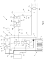
- a heating installation 1 is schematically illustrated in Figs 1-7 .
- the heating installation 1 is configured to heat a house or other building and to heat tap hot-water in the building.
- the heating installation according to the invention may as an alternative be configured to satisfy any other types of heating demands.
- the heating installation 1 comprises a first circuit C1 containing a first liquid medium, for instance in the form of water, and a second circuit C2 containing a second liquid medium, for instance in the form of water.
- the heating installation 1 comprises a thermal energy store 2, which is connected to the first circuit C1 in order to allow heat exchange between the thermal energy store 2 and the medium in the first circuit C1.
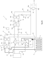
- the thermal energy store 2 is with advantage a vertical or horizontal ground heat exchanger, as illustrated in Figs 2-7 .
- a ground heat exchanger comprises collector pipes 3 installed in the ground, wherein a heat-carrier fluid is circulated through the collector pipes in order to absorb heat from the ground or discharge heat to the ground.
- the medium in the first circuit C1 is circulated through collector pipes 3 of the thermal energy store 2 and used as heat-carrier fluid.
- the collector pipes 3 are installed in vertical or inclined boreholes in the ground, wherein the space around the collector pipes 3 may be filled with groundwater or backfilled with thermally conductive grout in order to achieve good thermal contact between the ground material and the collector pipes.
- the collector pipes 3 are installed horizontally at a suitable depth in the ground.
- thermal energy store 2 in the form of a ground heat exchanger, heat energy may for instance be stored in the summer for later use in the winter.
- any other suitable type of thermal energy store 2 may also be used, such as for instance a thermal energy store formed by one or more accumulator tanks 4 of larger size, as illustrated in Fig 1 .
- heat energy may for instance be stored at night for later use in the daytime.
- the heating installation 1 comprises a first heat pump 5, which has an input side 5a connected to the first circuit C1 and which is configured to heat a medium by absorbing heat energy from the medium in the first circuit C1.
- the first heat pump 5 is configured to heat said medium by utilizing heat energy stored in the thermal energy store 2.
- the first heat pump 5 comprises an evaporator 5c, a condenser 5d, a compressor 5e and an expansion valve 5f, preferably an electromechanical expansion valve.
- the evaporator 5c of the first heat pump 5 is connected to the first circuit C1.
- the working medium of the first heat pump 5 absorbs heat energy via the evaporator 5c.
- Work is added via the compressor 5e, whereby the pressure and the temperature of the working medium is increased.
- heat energy is then, by heat exchange, emitted to a medium in a circuit C3 connected to the condenser 5d and the working medium of the heat pump is then returned to the evaporator 5c via the expansion valve 5f, the pressure and the temperature of the working medium being lowered when passing the expansion valve.
- the heating installation 1 comprises a first circulation pump 6, which is arranged in the first circuit C1 for controlling the flow of medium in the first circuit between the first heat pump 5 and the thermal energy store 2.
- the heating installation 1 further comprises cooling circuit CC containing a medium, a first heat exchanger 8 and a second heat exchanger 9.
- the first heat exchanger 8 has a first side 8a connected to the cooling circuit CC and a second side 8b connected to the first circuit C1 and is configured to transfer heat from the medium in the cooling circuit CC to the medium in the first circuit C1.
- the second heat exchanger 9 has a first side 9a connected to the cooling circuit CC and a second side 9b connected to the second circuit C2 and is configured to transfer heat from the medium in the cooling circuit CC to the medium in the second circuit C2.
- the cooling circuit CC is connected to a cooling system CS, which may be configured to cool an industrial process, a data centre, a server room, hospital equipment or any other type of heat emitting equipment.
- the cooling circuit CC may also be connected to a cooling system CS in the form of a refrigeration and/or freezing system.
- the heating installation 1 also comprises a second heat pump 10, which has an input side 10a connected to the second circuit C2 and which is configured to heat a medium by absorbing heat energy from the medium in the second circuit C2.
- the second heat pump 10 is configured to heat said medium by utilizing heat energy from the medium circulating in the cooling circuit CC.
- a circulation pump 11 is arranged in the second circuit C2 for controlling the flow of medium in the second circuit through the second side 9b of the second heat exchanger 9.
- the second heat pump 10 comprises an evaporator 10c, a condenser 10d, a compressor 10e and an expansion valve 10f, preferably an electromechanical expansion valve.
- the evaporator 10c of the second heat pump 10 is connected to the second circuit C2.
- the working medium of the second heat pump 10 absorbs heat energy via the evaporator 10c.
- Work is added via the compressor 10e, whereby the pressure and the temperature of the working medium is increased.
- heat energy is then, by heat exchange, emitted to a medium in a circuit C3, C4 connected to the condenser 10d and the working medium of the heat pump is then returned to the evaporator 10c via the expansion valve 10f, the pressure and the temperature of the working medium being lowered when passing the expansion valve.
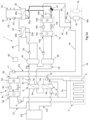
- a second circulation pump 12 is arranged in the first circuit C1 for controlling the flow of medium in the first circuit C1 between the first heat exchanger 8 and the thermal energy store 2.
- the second circulation pump 12 is operated in cooperation with the first circulation pump 6 in order to make the medium in the first circuit C1 flow through the second side 8b of the first heat exchanger 8 while absorbing heat energy from the medium circulating in the cooling circuit CC, and thereafter through the thermal energy store 2 in order to discharge heat energy to the thermal energy store 2 and thereby increase the temperature thereof.
- the medium in the first circuit C1 is directed directly from the first heat pump 5 to the thermal energy store 2 via a bypass line 14 without passing through the first heat exchanger 8.
- the medium circulating in the first circuit C1 may absorb heat energy from the thermal energy store 2 for use by the first heat pump 5.
- a circulation pump 13 is arranged in the cooling circuit CC for circulating the medium in this circuit, wherein the flow of medium through the first side 8a of the first heat exchanger 8 and through the first side 9a of the second heat exchanger 9 is controlled by means of this circulation pump 13.
- the above-mentioned heat emitting device 20 has the form of a heat exchanger, wherein this heat exchanger has a first side 20a connected to the fourth circuit C4 and a second side 20b connected to the tap hot-water circuit C5 and is configured to transfer heat from the medium in the fourth circuit C4 to the water in the tap hot-water circuit C5.
- the heating installation 1 comprises a heat exchanger 33, in the following referred to as third heat exchanger, which has a first side 33a connected to the second circuit C2 and a second side 33b connected to the water supply line 26 upstream of the heat emitting device 20, wherein this heat exchanger 33 is configured to preheat tap hot-water by transferring heat from the medium in the second circuit C2 to water in the water supply line 26.
- the heating installation 1 also comprises a second accumulator tank 34 arranged in the second circuit C2 for accumulating a part of the medium in the second circuit.
- the heating installation 1 comprises a third accumulator tank 40 arranged in the second circuit C2 for accumulating a part of the medium in the second circuit, wherein the first, second and third accumulator tanks 30, 34, 40 are arranged in series with each other in the second circuit C2 with the first accumulator tank 30 downstream of the second accumulator tank 34 and upstream of the third accumulator tank 40 as seen in the above-mentioned flow direction FD.
- the third accumulator tank 40 is arranged in the second circuit C2 downstream of the first accumulator tank 30 as seen in said flow direction FD.
- the heating installation 1 comprises a further heat exchanger 41, in the following referred to as fourth heat exchanger, which has a first side 41a connected to the third accumulator tank 40 in order to allow medium in the second circuit C2 to circulate between the third accumulator tank 40 and the fourth heat exchanger 41 and a second side 41b connected to the water supply line 26.
- a further circulation pump 42 is arranged in a conduit between the third accumulator tank 40 and the fourth heat exchanger 41 in order to control the circulation of medium between the third accumulator tank 40 and the fourth heat exchanger 41.
- the fourth heat exchanger 41 is configured to preheat tap hot-water by transferring heat from the medium in the second circuit C2 to the water in the water supply line 26.
- the third and fourth heat exchangers 33, 41 are arranged in series with each other in the water supply line 26, wherein the fourth heat exchanger 41 is connected to the water supply line 26 upstream of the third heat exchanger 33 to thereby allow the fourth heat exchanger 41 to preheat the tap hot-water in a first step and the third heat exchanger 33 to preheat the tap hot-water in a subsequent second step.
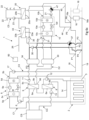
- the second heat pump 10 has its output side 10b connected to the third circuit C3 so that heat exchange between the working medium of the second heat pump 10 and the medium in the third circuit C3 is possible via the condenser 10d of the second heat pump 10.
- Heat energy extracted from the medium in the cooling circuit CC may hereby be utilized by the second heat pump 10 in order to increase the temperature of the medium flowing through the third circuit C3 and thereby contribute to the heating of the air in the building in question via the heat emitting devices 16 arranged in the third circuit C3.
- an inlet of the condenser 10d of the second heat pump is connected to the third circuit C3 via a first connecting conduit 44
- an outlet of the condenser 10d of the second heat pump is connected to the third circuit C3 via a second connecting conduit 45.
- Medium may flow from the third circuit C3 to the condenser 10d of the second heat pump via the first connecting conduit 44, through the condenser 10d of the second heat pump while absorbing heat from the working medium of the second heat pump 10, and then back to the third circuit C3 via the second connecting conduit 45.
- the first connecting conduit 44 is connected to the third circuit C3 at a point P5 located in the feed conduit 18, and the second connecting conduit 45 is connected to the third circuit C3 at another point P6 located in the feed conduit 18 downstream of the first-mentioned point P5.
- the circulation of medium between the feed conduit 18 and the condenser 10d of the second heat pump 10 is controlled by means of a circulation pump 46 arranged in the first connecting conduit 44.
- This circulation pump 46 could as an alternative be arranged in the second connecting conduit 45.
- the flow of medium between the second heat pump 10 and the third circuit C3 is controlled by means of the circulation pump 21 and a control valve 47 in the form of a three-way valve.
- the circulation pump 21 is in operation with the control valve 47 in a first setting position, medium is made to circulate between the condenser 10d of the second heat pump 10 and the heat emitting device 20, as illustrated with thick lines in Fig 5a .
- the second heat pump 10 is configured to emit heat energy for final heating of tap hot-water and/or in order to give an addition of heat to the medium in the third circuit C3.
- the second heat pump 10 could as an alternative be configured to emit heat energy for any other suitable heating purpose.
- the heating installation 1 comprises an electronic control device 50, which is configured to control the circulation of medium in the different circuits C1-C4 of the heating installation by controlling the circulation pumps 6, 11, 12, 17, 21, 31, 35, 36, 42, 46 and control valves 15, 37, 47 provided in these circuits.
- the electronic control device 50 is configured to control said circulation in dependence on temperature values representing the temperature of the medium at different places in the circuits C1-C4, wherein these temperature values are established by means of temperature sensors 51 connected to the electronic control device 50. Temperature sensors 51 included in the heating installation 1 are illustrated in Fig 1 , but have been omitted in the other figures.
Landscapes
- Engineering & Computer Science (AREA)
- Physics & Mathematics (AREA)
- Thermal Sciences (AREA)
- Chemical & Material Sciences (AREA)
- Combustion & Propulsion (AREA)
- Mechanical Engineering (AREA)
- General Engineering & Computer Science (AREA)
- Water Supply & Treatment (AREA)
- Steam Or Hot-Water Central Heating Systems (AREA)
- Central Heating Systems (AREA)
Claims (15)
- Heizungsanlage, umfassend:- einen ersten Kreislauf (C1), der ein Medium enthält;- eine erste Wärmepumpe (5), die eine mit dem ersten Kreislauf (C1) verbundene Eingangsseite (5a) aufweist und dazu ausgebildet ist, ein Medium durch Absorption von Wärmeenergie aus dem Medium in dem ersten Kreislauf (C1) zu erwärmen;- einen mit dem ersten Kreislauf (C1) verbundenen thermischen Energiespeicher (2), um einen Wärmeaustausch zwischen dem thermischen Energiespeicher (2) und dem Medium in dem ersten Kreislauf (C1) zu ermöglichen;- einen zweiten Kreislauf (C2), der ein Medium enthält; und- einen Kühlkreislauf (CC), der ein Medium enthält,wobei die Heizungsanlage (1) ferner umfasst:- eine zweite Wärmepumpe (10), die eine mit dem zweiten Kreislauf (C2) verbundene Eingangsseite aufweist und dazu ausgebildet ist, ein Medium durch Absorption von Wärmeenergie aus dem Medium in dem zweiten Kreislauf (C2) zu erwärmen;- einen ersten Wärmetauscher (8), der eine erste Seite (8a) aufweist, die mit dem Kühlkreislauf (CC) verbunden ist, und eine zweite Seite (8b), die mit dem ersten Kreislauf (C1) verbunden ist, und der dazu ausgebildet ist, Wärme von dem Medium in dem Kühlkreislauf (CC) zu dem Medium in dem ersten Kreislauf (C1) zu übertragen; und- einen zweiten Wärmetauscher (9), der eine erste Seite (9a) aufweist, die mit dem Kühlkreislauf (CC) verbunden ist, und eine zweite Seite (9b), die mit dem zweiten Kreislauf (C2) verbunden ist, und der dazu ausgebildet ist, Wärme von dem Medium in dem Kühlkreislauf (CC) zu dem Medium in dem zweiten Kreislauf (C2) zu übertragen.
- Heizungsanlage nach Anspruch 1, dadurch gekennzeichnet, dass der erste und der zweite Wärmetauscher (8, 9) in Reihe miteinander mit dem Kühlkreislauf (CC) verbunden sind.
- Heizungsanlage nach Anspruch 2, dadurch gekennzeichnet, dass der erste Wärmetauscher (8) im Kühlkreislauf (CC) stromabwärts des zweiten Wärmetauschers (9) angeordnet ist.
- Heizungsanlage gemäß einem der Ansprüche 1 bis 3, dadurch gekennzeichnet, dass die Heizungsanlage (1) eine erste Zirkulationspumpe (6) umfasst, die in dem ersten Kreislauf (C1) angeordnet ist, um den Fluss des Mediums in dem ersten Kreislauf (C1) zwischen der ersten Wärmepumpe (5) und dem thermischen Energiespeicher (2) zu steuern.
- Heizungsanlage nach Anspruch 4, dadurch gekennzeichnet, dass die Heizungsanlage (1) eine im ersten Kreislauf (C1) angeordnete zweite Zirkulationspumpe (12) oder ein im ersten Kreislauf (C1) angeordnetes Steuerventil (15) umfasst, um den Fluss des Mediums im ersten Kreislauf (C1) zwischen dem ersten Wärmetauscher (8) und dem thermischen Energiespeicher (2) zu steuern.
- Heizungsanlage gemäß einem der Ansprüche 1 bis 5, dadurch gekennzeichnet, dass die Heizungsanlage (1) umfasst:- einen ersten Speicherbehälter (30), der in dem zweiten Kreislauf (C2) angeordnet ist, um einen Teil des Mediums in dem zweiten Kreislauf zu speichern, wobei der erste Speicherbehälter (30) mit einem Verdampfer (10c) der zweiten Wärmepumpe (10) verbunden ist, um es dem Medium im zweiten Kreislauf (C2) zu ermöglichen, zwischen dem ersten Speicherbehälter (80) und dem Verdampfer (10c) der zweiten Wärmepumpe zu zirkulieren;- eine dritte Zirkulationspumpe (11), die in dem zweiten Kreislauf (C2) angeordnet ist, um den Fluss des Mediums in dem zweiten Kreislauf durch die zweite Seite (9b) des zweiten Wärmetauschers (9) hindurch und durch den ersten Sammeltank (30) hindurch zu steuern; und- eine vierte Zirkulationspumpe (31), die in einer Leitung zwischen dem ersten Speicherbehälter (30) und dem Verdampfer (10c) der zweiten Wärmepumpe (10) angeordnet ist und dazu ausgebildet ist, die Zirkulation des Mediums zwischen dem ersten Speicherbehälter (30) und dem Verdampfer (10c) der zweiten Wärmepumpe (10) zu steuern.
- Heizungsanlage gemäß einem der Ansprüche 1 bis 6, dadurch gekennzeichnet,- dass die Heizungsanlage (1) einen dritten Kreislauf (C3) umfasst, der ein Medium enthält;- dass die erste Wärmepumpe (5) mit ihrer Ausgangsseite (5b) mit dem dritten Kreislauf (C3) verbunden ist, so dass ein Wärmeaustausch zwischen dem Arbeitsmedium der ersten Wärmepumpe (5) und dem Medium im dritten Kreislauf (C3) über einen Kondensator (5d) der ersten Wärmepumpe (5) möglich ist; und- dass die Heizungsanlage (1) eine oder mehrere Wärmeabgabevorrichtungen (16) umfasst, die im dritten Kreislauf (C3) angeordnet sind, um Wärme vom Medium im dritten Kreislauf (C3) an Luft in einem Gebäude zu übertragen.
- Heizungsanlage nach Anspruch 7, dadurch gekennzeichnet, dass die zweite Wärmepumpe (10) mit ihrer Ausgangsseite (10b) mit dem dritten Kreislauf (C3) verbunden ist, so dass ein Wärmeaustausch zwischen dem Arbeitsmedium der zweiten Wärmepumpe (10) und dem Medium im dritten Kreislauf (C3) über einen Kondensator (10d) der zweiten Wärmepumpe (10) möglich ist.
- Heizungsanlage nach einem der Ansprüche 1-8, dadurch gekennzeichnet:- dass die Heizungsanlage (1) einen vierten Kreislauf (C4) umfasst, der ein Medium enthält;- dass die zweite Wärmepumpe (10) mit ihrer Ausgangsseite mit dem vierten Kreislauf (C4) verbunden ist, so dass ein Wärmeaustausch zwischen dem Arbeitsmedium der zweiten Wärmepumpe (10) und dem Medium im vierten Kreislauf (C4) über einen Kondensator (10d) der zweiten Wärmepumpe (10) möglich ist; und- dass die Heizungsanlage (1) eine im vierten Kreislauf (C4) angeordnete Wärmeabgabevorrichtung (20, 20') zur Erwärmung von Leitungswarmwasser durch Übertragung von Wärme aus dem Medium im vierten Kreislauf (C4) auf zu erwärmendes Wasser umfasst, um Leitungswarmwasser bereitzustellen.
- Heizungsanlage nach Anspruch 9, dadurch gekennzeichnet, dass die Heizungsanlage (1) einen dritten Wärmetauscher (33) umfasst, der eine erste Seite (83a) aufweist, die mit dem zweiten Kreislauf (C2) verbunden ist, und der eine zweite Seite (33b) aufweist, die mit einer Wasserversorgungsleitung (26) verbunden ist, und der dazu ausgebildet ist, Leitungswarmwasser durch Übertragung von Wärme vom Medium im zweiten Kreislauf (C2) zu Wasser in der Wasserversorgungsleitung (26) vorzuwärmen.
- Heizungsanlage nach Anspruch 10 in Verbindung mit Anspruch 6, dadurch gekennzeichnet:- dass die Heizungsanlage (1) einen zweiten Speicherbehälter (34) umfasst, der in dem zweiten Kreislauf (C2) angeordnet ist, um einen Teil des Mediums in dem zweiten Kreislauf zu speichern, wobei der erste und der zweite Speicherbehälter (30, 34) in dem zweiten Kreislauf (C2) in Reihe zueinander angeordnet sind;- dass der dritte Wärmetauscher (33) mit seiner ersten Seite (33a) mit dem zweiten Speicherbehälter (34) verbunden ist, damit das Medium im zweiten Kreislauf (C2) zwischen dem zweiten Speicherbehälter (34) und dem dritten Wärmetauscher (33) zirkulieren kann; und- dass die Heizungsanlage (1) eine fünfte Zirkulationspumpe (35) umfasst, die in einer Leitung zwischen dem zweiten Speicherbehälter (34) und dem dritten Wärmetauscher (33) angeordnet ist und die dazu ausgebildet ist, die Zirkulation des Mediums zwischen dem zweiten Speicherbehälter (34) und dem dritten Wärmetauscher (33) zu steuern.
- Heizungsanlage nach Anspruch 11, dadurch gekennzeichnet, dass der zweite Speicherbehälter (34), bei Betrachtung in einer Flussrichtung (FD) von einem Auslass (9c) des zweiten Wärmetauschers (9) zu einem Einlass (9d) desselben, im zweiten Kreislauf (C2) stromaufwärts des ersten Speicherbehälters (30) angeordnet ist.
- Heizungsanlage nach Anspruch 11 oder 12, dadurch gekennzeichnet, dass der zweite Speicherbehälter (34) mit dem dritten Kreislauf (C3) verbunden ist, um Medium zu gestatten, zwischen dem zweiten Speicherbehälter (34) und dem dritten Kreislauf (C3) zu zirkulieren.
- Heizungsanlage nach einem der Ansprüche 11-13, dadurch gekennzeichnet:- dass die Heizungsanlage (1) einen dritten Speicherbehälter (40) umfasst, der im zweiten Kreislauf (C2) angeordnet ist, um einen Teil des Mediums im zweiten Kreislauf zu speichern, wobei der erste, der zweite und der dritte Speicherbehälter (30, 34, 40) im zweiten Kreislauf (C2) in Reihe zueinander angeordnet sind, wobei der dritte Speicherbehälter (40) im zweiten Kreislauf (C2), bei Betrachtung in der Flussrichtung (FD), stromabwärts des ersten Speicherbehälters (30) angeordnet ist;- dass die Heizungsanlage (1) einen vierten Wärmetauscher (41) umfasst, der eine erste Seite (41a) aufweist, die mit dem dritten Speicherbehälter (40) verbunden ist, um Medium im zweiten Kreislauf (C2) zu gestatten, zwischen dem dritten Speicherbehälter (40) und dem vierten Wärmetauscher (41) zu zirkulieren, und der eine zweite Seite (41b) aufweist, die mit der Wasserversorgungsleitung (26) verbunden ist, wobei der vierte Wärmetauscher (41) dazu ausgebildet ist, Leitungswarmwasser vorzuwärmen, indem er Wärme von dem Medium in dem zweiten Kreislauf (C2) zu dem Wasser in der Wasserzufuhrleitung (26) überträgt;- dass die Heizungsanlage (1) eine sechste Zirkulationspumpe (42) umfasst, die in einer Leitung zwischen dem dritten Speicherbehälter (40) und dem vierten Wärmetauscher (41) angeordnet ist und die dazu ausgebildet ist, die Zirkulation des Mediums zwischen dem dritten Pufferspeicher (40) und dem vierten Wärmetauscher (41) zu steuern; und- dass der dritte und der vierte Wärmetauscher (33, 41) in der Wasserzufuhrleitung (26) in Reihe zueinander angeordnet sind, wobei der vierte Wärmetauscher (41) mit der Wasserversorgungsleitung (26) stromaufwärts des dritten Wärmetauschers (33) verbunden ist, um dadurch dem vierten Wärmetauscher (41) zu gestatten, das Leitungswarmwasser in einem ersten Schritt vorzuwärmen und dem dritte Wärmetauscher (33) zu gestatten, das Leitungswarmwasser in einem nachfolgenden zweiten Schritt vorzuwärmen.
- Heizungsanlage nach einem der Ansprüche 1 bis 14, dadurch gekennzeichnet, dass der thermische Energiespeicher (2) ein Erdwärmetauscher ist.
Priority Applications (5)
| Application Number | Priority Date | Filing Date | Title |
|---|---|---|---|
| EP21216044.4A EP4198407B1 (de) | 2021-12-20 | 2021-12-20 | Heizungsinstallation |
| US18/718,650 US20250043962A1 (en) | 2021-12-20 | 2022-12-15 | Heating installation |
| CN202280080080.9A CN118355234A (zh) | 2021-12-20 | 2022-12-15 | 加热设备 |
| CA3236795A CA3236795A1 (en) | 2021-12-20 | 2022-12-15 | Heating installation |
| PCT/EP2022/086117 WO2023117677A1 (en) | 2021-12-20 | 2022-12-15 | Heating installation |
Applications Claiming Priority (1)
| Application Number | Priority Date | Filing Date | Title |
|---|---|---|---|
| EP21216044.4A EP4198407B1 (de) | 2021-12-20 | 2021-12-20 | Heizungsinstallation |
Publications (3)
| Publication Number | Publication Date |
|---|---|
| EP4198407A1 EP4198407A1 (de) | 2023-06-21 |
| EP4198407C0 EP4198407C0 (de) | 2025-06-11 |
| EP4198407B1 true EP4198407B1 (de) | 2025-06-11 |
Family
ID=79021779
Family Applications (1)
| Application Number | Title | Priority Date | Filing Date |
|---|---|---|---|
| EP21216044.4A Active EP4198407B1 (de) | 2021-12-20 | 2021-12-20 | Heizungsinstallation |
Country Status (5)
| Country | Link |
|---|---|
| US (1) | US20250043962A1 (de) |
| EP (1) | EP4198407B1 (de) |
| CN (1) | CN118355234A (de) |
| CA (1) | CA3236795A1 (de) |
| WO (1) | WO2023117677A1 (de) |
Families Citing this family (2)
| Publication number | Priority date | Publication date | Assignee | Title |
|---|---|---|---|---|
| EP4495489B1 (de) * | 2023-07-18 | 2025-10-01 | Energy Machines ApS | Lokale heizungsanlage und heizungssystem mit solch einer lokalen heizungsanlage |
| WO2025054633A1 (en) | 2023-10-23 | 2025-03-13 | Schlumberger Technology Corporation | Thermal system with exhaust heat exchanger |
Family Cites Families (3)
| Publication number | Priority date | Publication date | Assignee | Title |
|---|---|---|---|---|
| KR100998483B1 (ko) * | 2010-04-26 | 2010-12-06 | 주식회사 제이앤지 | 지열히트펌프를 이용한 모듈멀티형 냉난방시스템 |
| SE539398C2 (sv) * | 2014-11-10 | 2017-09-12 | Energy Machines S A | Värmeanläggning innefattande värmepump med växelvis anslutbara ackumulatortankar |
| KR101623746B1 (ko) * | 2015-11-05 | 2016-05-24 | 주식회사 제이앤지 | 지열 에너지를 활용한 2단 가열식 지열 시스템 |
-
2021
- 2021-12-20 EP EP21216044.4A patent/EP4198407B1/de active Active
-
2022
- 2022-12-15 CA CA3236795A patent/CA3236795A1/en active Pending
- 2022-12-15 US US18/718,650 patent/US20250043962A1/en active Pending
- 2022-12-15 WO PCT/EP2022/086117 patent/WO2023117677A1/en not_active Ceased
- 2022-12-15 CN CN202280080080.9A patent/CN118355234A/zh active Pending
Also Published As
| Publication number | Publication date |
|---|---|
| CN118355234A (zh) | 2024-07-16 |
| EP4198407A1 (de) | 2023-06-21 |
| US20250043962A1 (en) | 2025-02-06 |
| CA3236795A1 (en) | 2023-06-29 |
| EP4198407C0 (de) | 2025-06-11 |
| WO2023117677A1 (en) | 2023-06-29 |
Similar Documents
| Publication | Publication Date | Title |
|---|---|---|
| CN111425915B (zh) | 区域热能分配系统 | |
| US10612796B2 (en) | Heating installation | |
| US11624510B2 (en) | District energy distributing system | |
| EP3885657B1 (de) | Verfahren zur verteilung von energie auf mehrere gebäude | |
| US20120272948A1 (en) | Heat storage system | |
| EP3726146B1 (de) | Kombiniertes heiz- und kühlsystem | |
| CN101821562A (zh) | 热泵装置 | |
| EP4198407B1 (de) | Heizungsinstallation | |
| US10274207B2 (en) | Heating installation | |
| CN102483243A (zh) | 用于向主系统中循环排水的热泵的对称中间蓄水箱 | |
| EP3803217B1 (de) | Heiz- und kühlsystem, entsprechendes verfahren und verwendung des systems | |
| EP4464944B1 (de) | Heizungsanlage | |
| EP4495489B1 (de) | Lokale heizungsanlage und heizungssystem mit solch einer lokalen heizungsanlage | |
| WO2023111291A1 (en) | Heating network with heating and cooling applicability | |
| EP3862637A1 (de) | Wärmespeicheranordnung und zur steuerung solch einer anordnung konfiguriertes steuergerät | |
| EP3207314B1 (de) | Verfahren und system zum aufwärmen von leitungswasser | |
| GB2187272A (en) | Heat exchange apparatus |
Legal Events
| Date | Code | Title | Description |
|---|---|---|---|
| PUAI | Public reference made under article 153(3) epc to a published international application that has entered the european phase |
Free format text: ORIGINAL CODE: 0009012 |
|
| STAA | Information on the status of an ep patent application or granted ep patent |
Free format text: STATUS: THE APPLICATION HAS BEEN PUBLISHED |
|
| AK | Designated contracting states |
Kind code of ref document: A1 Designated state(s): AL AT BE BG CH CY CZ DE DK EE ES FI FR GB GR HR HU IE IS IT LI LT LU LV MC MK MT NL NO PL PT RO RS SE SI SK SM TR |
|
| STAA | Information on the status of an ep patent application or granted ep patent |
Free format text: STATUS: REQUEST FOR EXAMINATION WAS MADE |
|
| 17P | Request for examination filed |
Effective date: 20231212 |
|
| RBV | Designated contracting states (corrected) |
Designated state(s): AL AT BE BG CH CY CZ DE DK EE ES FI FR GB GR HR HU IE IS IT LI LT LU LV MC MK MT NL NO PL PT RO RS SE SI SK SM TR |
|
| RAP3 | Party data changed (applicant data changed or rights of an application transferred) |
Owner name: ENERGY MACHINES APS |
|
| GRAP | Despatch of communication of intention to grant a patent |
Free format text: ORIGINAL CODE: EPIDOSNIGR1 |
|
| STAA | Information on the status of an ep patent application or granted ep patent |
Free format text: STATUS: GRANT OF PATENT IS INTENDED |
|
| INTG | Intention to grant announced |
Effective date: 20250224 |
|
| GRAS | Grant fee paid |
Free format text: ORIGINAL CODE: EPIDOSNIGR3 |
|
| GRAA | (expected) grant |
Free format text: ORIGINAL CODE: 0009210 |
|
| STAA | Information on the status of an ep patent application or granted ep patent |
Free format text: STATUS: THE PATENT HAS BEEN GRANTED |
|
| AK | Designated contracting states |
Kind code of ref document: B1 Designated state(s): AL AT BE BG CH CY CZ DE DK EE ES FI FR GB GR HR HU IE IS IT LI LT LU LV MC MK MT NL NO PL PT RO RS SE SI SK SM TR |
|
| REG | Reference to a national code |
Ref country code: GB Ref legal event code: FG4D |
|
| REG | Reference to a national code |
Ref country code: CH Ref legal event code: EP |
|
| REG | Reference to a national code |
Ref country code: DE Ref legal event code: R096 Ref document number: 602021032069 Country of ref document: DE |
|
| REG | Reference to a national code |
Ref country code: IE Ref legal event code: FG4D |
|
| U01 | Request for unitary effect filed |
Effective date: 20250618 |
|
| U07 | Unitary effect registered |
Designated state(s): AT BE BG DE DK EE FI FR IT LT LU LV MT NL PT RO SE SI Effective date: 20250630 |
|
| PG25 | Lapsed in a contracting state [announced via postgrant information from national office to epo] |
Ref country code: ES Free format text: LAPSE BECAUSE OF FAILURE TO SUBMIT A TRANSLATION OF THE DESCRIPTION OR TO PAY THE FEE WITHIN THE PRESCRIBED TIME-LIMIT Effective date: 20250611 |
|
| PG25 | Lapsed in a contracting state [announced via postgrant information from national office to epo] |
Ref country code: GR Free format text: LAPSE BECAUSE OF FAILURE TO SUBMIT A TRANSLATION OF THE DESCRIPTION OR TO PAY THE FEE WITHIN THE PRESCRIBED TIME-LIMIT Effective date: 20250912 Ref country code: NO Free format text: LAPSE BECAUSE OF FAILURE TO SUBMIT A TRANSLATION OF THE DESCRIPTION OR TO PAY THE FEE WITHIN THE PRESCRIBED TIME-LIMIT Effective date: 20250911 |
|
| PG25 | Lapsed in a contracting state [announced via postgrant information from national office to epo] |
Ref country code: HR Free format text: LAPSE BECAUSE OF FAILURE TO SUBMIT A TRANSLATION OF THE DESCRIPTION OR TO PAY THE FEE WITHIN THE PRESCRIBED TIME-LIMIT Effective date: 20250611 |
|
| PG25 | Lapsed in a contracting state [announced via postgrant information from national office to epo] |
Ref country code: RS Free format text: LAPSE BECAUSE OF FAILURE TO SUBMIT A TRANSLATION OF THE DESCRIPTION OR TO PAY THE FEE WITHIN THE PRESCRIBED TIME-LIMIT Effective date: 20250911 |