EP4198407B1 - Heating installation - Google Patents
Heating installation Download PDFInfo
- Publication number
- EP4198407B1 EP4198407B1 EP21216044.4A EP21216044A EP4198407B1 EP 4198407 B1 EP4198407 B1 EP 4198407B1 EP 21216044 A EP21216044 A EP 21216044A EP 4198407 B1 EP4198407 B1 EP 4198407B1
- Authority
- EP
- European Patent Office
- Prior art keywords
- circuit
- medium
- heat
- heating installation
- heat exchanger
- Prior art date
- Legal status (The legal status is an assumption and is not a legal conclusion. Google has not performed a legal analysis and makes no representation as to the accuracy of the status listed.)
- Active
Links
Images






Classifications
-
- F—MECHANICAL ENGINEERING; LIGHTING; HEATING; WEAPONS; BLASTING
- F24—HEATING; RANGES; VENTILATING
- F24D—DOMESTIC- OR SPACE-HEATING SYSTEMS, e.g. CENTRAL HEATING SYSTEMS; DOMESTIC HOT-WATER SUPPLY SYSTEMS; ELEMENTS OR COMPONENTS THEREFOR
- F24D11/00—Central heating systems using heat accumulated in storage masses
- F24D11/02—Central heating systems using heat accumulated in storage masses using heat pumps
- F24D11/0214—Central heating systems using heat accumulated in storage masses using heat pumps water heating system
- F24D11/0235—Central heating systems using heat accumulated in storage masses using heat pumps water heating system with recuperation of waste energy
-
- F—MECHANICAL ENGINEERING; LIGHTING; HEATING; WEAPONS; BLASTING
- F24—HEATING; RANGES; VENTILATING
- F24D—DOMESTIC- OR SPACE-HEATING SYSTEMS, e.g. CENTRAL HEATING SYSTEMS; DOMESTIC HOT-WATER SUPPLY SYSTEMS; ELEMENTS OR COMPONENTS THEREFOR
- F24D17/00—Domestic hot-water supply systems
- F24D17/02—Domestic hot-water supply systems using heat pumps
-
- F—MECHANICAL ENGINEERING; LIGHTING; HEATING; WEAPONS; BLASTING
- F24—HEATING; RANGES; VENTILATING
- F24D—DOMESTIC- OR SPACE-HEATING SYSTEMS, e.g. CENTRAL HEATING SYSTEMS; DOMESTIC HOT-WATER SUPPLY SYSTEMS; ELEMENTS OR COMPONENTS THEREFOR
- F24D19/00—Details
- F24D19/10—Arrangement or mounting of control or safety devices
- F24D19/1006—Arrangement or mounting of control or safety devices for water heating systems
- F24D19/1066—Arrangement or mounting of control or safety devices for water heating systems for the combination of central heating and domestic hot water
- F24D19/1072—Arrangement or mounting of control or safety devices for water heating systems for the combination of central heating and domestic hot water the system uses a heat pump
-
- F—MECHANICAL ENGINEERING; LIGHTING; HEATING; WEAPONS; BLASTING
- F24—HEATING; RANGES; VENTILATING
- F24D—DOMESTIC- OR SPACE-HEATING SYSTEMS, e.g. CENTRAL HEATING SYSTEMS; DOMESTIC HOT-WATER SUPPLY SYSTEMS; ELEMENTS OR COMPONENTS THEREFOR
- F24D3/00—Hot-water central heating systems
- F24D3/08—Hot-water central heating systems in combination with systems for domestic hot-water supply
-
- F—MECHANICAL ENGINEERING; LIGHTING; HEATING; WEAPONS; BLASTING
- F24—HEATING; RANGES; VENTILATING
- F24D—DOMESTIC- OR SPACE-HEATING SYSTEMS, e.g. CENTRAL HEATING SYSTEMS; DOMESTIC HOT-WATER SUPPLY SYSTEMS; ELEMENTS OR COMPONENTS THEREFOR
- F24D3/00—Hot-water central heating systems
- F24D3/18—Hot-water central heating systems using heat pumps
-
- F—MECHANICAL ENGINEERING; LIGHTING; HEATING; WEAPONS; BLASTING
- F24—HEATING; RANGES; VENTILATING
- F24D—DOMESTIC- OR SPACE-HEATING SYSTEMS, e.g. CENTRAL HEATING SYSTEMS; DOMESTIC HOT-WATER SUPPLY SYSTEMS; ELEMENTS OR COMPONENTS THEREFOR
- F24D2200/00—Heat sources or energy sources
- F24D2200/11—Geothermal energy
-
- F—MECHANICAL ENGINEERING; LIGHTING; HEATING; WEAPONS; BLASTING
- F24—HEATING; RANGES; VENTILATING
- F24D—DOMESTIC- OR SPACE-HEATING SYSTEMS, e.g. CENTRAL HEATING SYSTEMS; DOMESTIC HOT-WATER SUPPLY SYSTEMS; ELEMENTS OR COMPONENTS THEREFOR
- F24D2200/00—Heat sources or energy sources
- F24D2200/12—Heat pump
- F24D2200/123—Compression type heat pumps
-
- F—MECHANICAL ENGINEERING; LIGHTING; HEATING; WEAPONS; BLASTING
- F24—HEATING; RANGES; VENTILATING
- F24D—DOMESTIC- OR SPACE-HEATING SYSTEMS, e.g. CENTRAL HEATING SYSTEMS; DOMESTIC HOT-WATER SUPPLY SYSTEMS; ELEMENTS OR COMPONENTS THEREFOR
- F24D2200/00—Heat sources or energy sources
- F24D2200/16—Waste heat
-
- F—MECHANICAL ENGINEERING; LIGHTING; HEATING; WEAPONS; BLASTING
- F24—HEATING; RANGES; VENTILATING
- F24D—DOMESTIC- OR SPACE-HEATING SYSTEMS, e.g. CENTRAL HEATING SYSTEMS; DOMESTIC HOT-WATER SUPPLY SYSTEMS; ELEMENTS OR COMPONENTS THEREFOR
- F24D2220/00—Components of central heating installations excluding heat sources
- F24D2220/08—Storage tanks
Definitions
- the object of the present invention is to provide a heating installation of the above-mentioned type that is capable of efficiently utilizing waste heat from a cooling circuit in a new a favourable manner.
- the heating installation according to the invention comprises:
- the first heat pump is configured to satisfy a heating demand by utilizing heat energy stored in the thermal energy store
- the second heat pump is configured to satisfy a heating demand by utilizing heat energy from the medium in the cooling circuit
- heat energy from the medium in the cooling circuit is transferred to the input side of the second heat pump via the second heat exchanger and the second circuit.
- heat energy from the medium in the cooling circuit may also be transferred to the thermal energy store in order to increase the temperature of the thermal energy store and thereby increase the amount of heat energy stored therein.
- the medium in the cooling circuit is heated by waste heat of a cooling process and used as an energy source by the heating installation.
- the waste heat of the cooling process may be utilized for suitable heating purposes instead of being wasted.
- a cooling process such as for instance a cooling process associated with the cooling of a data centre or hospital equipment or with the cooling of foodstuffs in a supermarket, is often producing waste heat continuously with low variations in temperature and quantity, wherein the temperature of the medium in a cooling circuit included in a cooling system configured to perform such a cooling process often has a temperature in the range of 20-30°C.
- the waste heat of such a cooling process is favourable for use as an energy source in a heating installation, for instance in a heating installation configured to satisfy heating demands in a building.
- the waste heat of the cooling process may be used as an energy source by the second heat pump in order to heat a medium in a circuit connected to the output side of the second heat pump.
- heat energy derived from the waste heat of the cooling process may be stored in the thermal energy store for later use by the first heat pump during periods with higher heating demands. In this manner, heat energy derived from the waste heat of the cooling process may for instance be stored in the summer for later use in the winter, or stored at night for later use in the daytime.
- the first and second heat exchangers are connected to the cooling circuit in series with each other, preferably with the first heat exchanger arranged in the cooling circuit downstream of the second heat exchanger.
- heat energy of higher temperature quality may be transferred from the medium in the cooling circuit to the second circuit via the second heat exchanger in a first step, whereupon heat energy of lower temperature quality may be transferred from the medium in the cooling circuit to the thermal energy store via the first heat exchanger and the first circuit in a subsequent second step.
- the thermal energy store is with advantage a ground heat exchanger.
- the thermal energy supplied to the thermal energy store from the cooling circuit is stored in the ground and/or in groundwater.
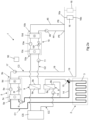
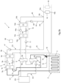
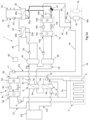
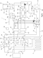
- a heating installation 1 is schematically illustrated in Figs 1-7 .
- the heating installation 1 is configured to heat a house or other building and to heat tap hot-water in the building.
- the heating installation according to the invention may as an alternative be configured to satisfy any other types of heating demands.
- the heating installation 1 comprises a first circuit C1 containing a first liquid medium, for instance in the form of water, and a second circuit C2 containing a second liquid medium, for instance in the form of water.
- the heating installation 1 comprises a thermal energy store 2, which is connected to the first circuit C1 in order to allow heat exchange between the thermal energy store 2 and the medium in the first circuit C1.
- the thermal energy store 2 is with advantage a vertical or horizontal ground heat exchanger, as illustrated in Figs 2-7 .
- a ground heat exchanger comprises collector pipes 3 installed in the ground, wherein a heat-carrier fluid is circulated through the collector pipes in order to absorb heat from the ground or discharge heat to the ground.
- the medium in the first circuit C1 is circulated through collector pipes 3 of the thermal energy store 2 and used as heat-carrier fluid.
- the collector pipes 3 are installed in vertical or inclined boreholes in the ground, wherein the space around the collector pipes 3 may be filled with groundwater or backfilled with thermally conductive grout in order to achieve good thermal contact between the ground material and the collector pipes.
- the collector pipes 3 are installed horizontally at a suitable depth in the ground.
- thermal energy store 2 in the form of a ground heat exchanger, heat energy may for instance be stored in the summer for later use in the winter.
- any other suitable type of thermal energy store 2 may also be used, such as for instance a thermal energy store formed by one or more accumulator tanks 4 of larger size, as illustrated in Fig 1 .
- heat energy may for instance be stored at night for later use in the daytime.
- the heating installation 1 comprises a first heat pump 5, which has an input side 5a connected to the first circuit C1 and which is configured to heat a medium by absorbing heat energy from the medium in the first circuit C1.
- the first heat pump 5 is configured to heat said medium by utilizing heat energy stored in the thermal energy store 2.
- the first heat pump 5 comprises an evaporator 5c, a condenser 5d, a compressor 5e and an expansion valve 5f, preferably an electromechanical expansion valve.
- the evaporator 5c of the first heat pump 5 is connected to the first circuit C1.
- the working medium of the first heat pump 5 absorbs heat energy via the evaporator 5c.
- Work is added via the compressor 5e, whereby the pressure and the temperature of the working medium is increased.
- heat energy is then, by heat exchange, emitted to a medium in a circuit C3 connected to the condenser 5d and the working medium of the heat pump is then returned to the evaporator 5c via the expansion valve 5f, the pressure and the temperature of the working medium being lowered when passing the expansion valve.
- the heating installation 1 comprises a first circulation pump 6, which is arranged in the first circuit C1 for controlling the flow of medium in the first circuit between the first heat pump 5 and the thermal energy store 2.
- the heating installation 1 further comprises cooling circuit CC containing a medium, a first heat exchanger 8 and a second heat exchanger 9.
- the first heat exchanger 8 has a first side 8a connected to the cooling circuit CC and a second side 8b connected to the first circuit C1 and is configured to transfer heat from the medium in the cooling circuit CC to the medium in the first circuit C1.
- the second heat exchanger 9 has a first side 9a connected to the cooling circuit CC and a second side 9b connected to the second circuit C2 and is configured to transfer heat from the medium in the cooling circuit CC to the medium in the second circuit C2.
- the cooling circuit CC is connected to a cooling system CS, which may be configured to cool an industrial process, a data centre, a server room, hospital equipment or any other type of heat emitting equipment.
- the cooling circuit CC may also be connected to a cooling system CS in the form of a refrigeration and/or freezing system.
- the heating installation 1 also comprises a second heat pump 10, which has an input side 10a connected to the second circuit C2 and which is configured to heat a medium by absorbing heat energy from the medium in the second circuit C2.
- the second heat pump 10 is configured to heat said medium by utilizing heat energy from the medium circulating in the cooling circuit CC.
- a circulation pump 11 is arranged in the second circuit C2 for controlling the flow of medium in the second circuit through the second side 9b of the second heat exchanger 9.
- the second heat pump 10 comprises an evaporator 10c, a condenser 10d, a compressor 10e and an expansion valve 10f, preferably an electromechanical expansion valve.
- the evaporator 10c of the second heat pump 10 is connected to the second circuit C2.
- the working medium of the second heat pump 10 absorbs heat energy via the evaporator 10c.
- Work is added via the compressor 10e, whereby the pressure and the temperature of the working medium is increased.
- heat energy is then, by heat exchange, emitted to a medium in a circuit C3, C4 connected to the condenser 10d and the working medium of the heat pump is then returned to the evaporator 10c via the expansion valve 10f, the pressure and the temperature of the working medium being lowered when passing the expansion valve.
- a second circulation pump 12 is arranged in the first circuit C1 for controlling the flow of medium in the first circuit C1 between the first heat exchanger 8 and the thermal energy store 2.
- the second circulation pump 12 is operated in cooperation with the first circulation pump 6 in order to make the medium in the first circuit C1 flow through the second side 8b of the first heat exchanger 8 while absorbing heat energy from the medium circulating in the cooling circuit CC, and thereafter through the thermal energy store 2 in order to discharge heat energy to the thermal energy store 2 and thereby increase the temperature thereof.
- the medium in the first circuit C1 is directed directly from the first heat pump 5 to the thermal energy store 2 via a bypass line 14 without passing through the first heat exchanger 8.
- the medium circulating in the first circuit C1 may absorb heat energy from the thermal energy store 2 for use by the first heat pump 5.
- a circulation pump 13 is arranged in the cooling circuit CC for circulating the medium in this circuit, wherein the flow of medium through the first side 8a of the first heat exchanger 8 and through the first side 9a of the second heat exchanger 9 is controlled by means of this circulation pump 13.
- the above-mentioned heat emitting device 20 has the form of a heat exchanger, wherein this heat exchanger has a first side 20a connected to the fourth circuit C4 and a second side 20b connected to the tap hot-water circuit C5 and is configured to transfer heat from the medium in the fourth circuit C4 to the water in the tap hot-water circuit C5.
- the heating installation 1 comprises a heat exchanger 33, in the following referred to as third heat exchanger, which has a first side 33a connected to the second circuit C2 and a second side 33b connected to the water supply line 26 upstream of the heat emitting device 20, wherein this heat exchanger 33 is configured to preheat tap hot-water by transferring heat from the medium in the second circuit C2 to water in the water supply line 26.
- the heating installation 1 also comprises a second accumulator tank 34 arranged in the second circuit C2 for accumulating a part of the medium in the second circuit.
- the heating installation 1 comprises a third accumulator tank 40 arranged in the second circuit C2 for accumulating a part of the medium in the second circuit, wherein the first, second and third accumulator tanks 30, 34, 40 are arranged in series with each other in the second circuit C2 with the first accumulator tank 30 downstream of the second accumulator tank 34 and upstream of the third accumulator tank 40 as seen in the above-mentioned flow direction FD.
- the third accumulator tank 40 is arranged in the second circuit C2 downstream of the first accumulator tank 30 as seen in said flow direction FD.
- the heating installation 1 comprises a further heat exchanger 41, in the following referred to as fourth heat exchanger, which has a first side 41a connected to the third accumulator tank 40 in order to allow medium in the second circuit C2 to circulate between the third accumulator tank 40 and the fourth heat exchanger 41 and a second side 41b connected to the water supply line 26.
- a further circulation pump 42 is arranged in a conduit between the third accumulator tank 40 and the fourth heat exchanger 41 in order to control the circulation of medium between the third accumulator tank 40 and the fourth heat exchanger 41.
- the fourth heat exchanger 41 is configured to preheat tap hot-water by transferring heat from the medium in the second circuit C2 to the water in the water supply line 26.
- the third and fourth heat exchangers 33, 41 are arranged in series with each other in the water supply line 26, wherein the fourth heat exchanger 41 is connected to the water supply line 26 upstream of the third heat exchanger 33 to thereby allow the fourth heat exchanger 41 to preheat the tap hot-water in a first step and the third heat exchanger 33 to preheat the tap hot-water in a subsequent second step.
- the second heat pump 10 has its output side 10b connected to the third circuit C3 so that heat exchange between the working medium of the second heat pump 10 and the medium in the third circuit C3 is possible via the condenser 10d of the second heat pump 10.
- Heat energy extracted from the medium in the cooling circuit CC may hereby be utilized by the second heat pump 10 in order to increase the temperature of the medium flowing through the third circuit C3 and thereby contribute to the heating of the air in the building in question via the heat emitting devices 16 arranged in the third circuit C3.
- an inlet of the condenser 10d of the second heat pump is connected to the third circuit C3 via a first connecting conduit 44
- an outlet of the condenser 10d of the second heat pump is connected to the third circuit C3 via a second connecting conduit 45.
- Medium may flow from the third circuit C3 to the condenser 10d of the second heat pump via the first connecting conduit 44, through the condenser 10d of the second heat pump while absorbing heat from the working medium of the second heat pump 10, and then back to the third circuit C3 via the second connecting conduit 45.
- the first connecting conduit 44 is connected to the third circuit C3 at a point P5 located in the feed conduit 18, and the second connecting conduit 45 is connected to the third circuit C3 at another point P6 located in the feed conduit 18 downstream of the first-mentioned point P5.
- the circulation of medium between the feed conduit 18 and the condenser 10d of the second heat pump 10 is controlled by means of a circulation pump 46 arranged in the first connecting conduit 44.
- This circulation pump 46 could as an alternative be arranged in the second connecting conduit 45.
- the flow of medium between the second heat pump 10 and the third circuit C3 is controlled by means of the circulation pump 21 and a control valve 47 in the form of a three-way valve.
- the circulation pump 21 is in operation with the control valve 47 in a first setting position, medium is made to circulate between the condenser 10d of the second heat pump 10 and the heat emitting device 20, as illustrated with thick lines in Fig 5a .
- the second heat pump 10 is configured to emit heat energy for final heating of tap hot-water and/or in order to give an addition of heat to the medium in the third circuit C3.
- the second heat pump 10 could as an alternative be configured to emit heat energy for any other suitable heating purpose.
- the heating installation 1 comprises an electronic control device 50, which is configured to control the circulation of medium in the different circuits C1-C4 of the heating installation by controlling the circulation pumps 6, 11, 12, 17, 21, 31, 35, 36, 42, 46 and control valves 15, 37, 47 provided in these circuits.
- the electronic control device 50 is configured to control said circulation in dependence on temperature values representing the temperature of the medium at different places in the circuits C1-C4, wherein these temperature values are established by means of temperature sensors 51 connected to the electronic control device 50. Temperature sensors 51 included in the heating installation 1 are illustrated in Fig 1 , but have been omitted in the other figures.
Landscapes
- Engineering & Computer Science (AREA)
- Physics & Mathematics (AREA)
- Thermal Sciences (AREA)
- Chemical & Material Sciences (AREA)
- Combustion & Propulsion (AREA)
- Mechanical Engineering (AREA)
- General Engineering & Computer Science (AREA)
- Water Supply & Treatment (AREA)
- Steam Or Hot-Water Central Heating Systems (AREA)
- Central Heating Systems (AREA)
Description
- The present invention relates to a heating installation.
- Heating installations with a heat pump that utilizes heat energy stored in a ground heat exchanger or other type of thermal energy store in order to satisfy different types of heating demands are previously known in various configurations. Such a heating installation may for instance be used in order to heat air and tap hot-water in a building. During periods with higher heating demands, heat energy may be extracted from the thermal energy store by means of a heat-carrier fluid that circulates between the thermal energy store and the heat pump. During periods with lower heating demands, heat energy may instead be transferred to the thermal energy store by means of the circulating heat-carrier fluid in order to increase the amount of heat energy stored in the thermal energy store. A heating installation of this type is previously known from
US 2017/0370622 A1 . - The object of the present invention is to provide a heating installation of the above-mentioned type that is capable of efficiently utilizing waste heat from a cooling circuit in a new a favourable manner.
- According to the invention, said object is achieved by means of a heating installation having the features defined in
claim 1. - The heating installation according to the invention comprises:
- a first circuit containing a medium;
- a first heat pump, which has an input side connected to the first circuit and which is configured to heat a medium by absorbing heat energy from the medium in the first circuit;
- a thermal energy store connected to the first circuit in order to allow heat exchange between the thermal energy store and the medium in the first circuit;
- a second circuit containing a medium;
- a cooling circuit containing a medium;
- a second heat pump, which has an input side connected to the second circuit and which is configured to heat a medium by absorbing heat energy from the medium in the second circuit;
- a first heat exchanger, which has a first side connected to said cooling circuit and a second side connected to the first circuit and which is configured to transfer waste heat from the medium in the cooling circuit to the medium in the first circuit; and
- a second heat exchanger, which has a first side connected to the cooling circuit and a second side connected to the second circuit and which is configured to transfer waste heat from the medium in the cooling circuit to the medium in the second circuit.
- In the heating installation according to the invention, the first heat pump is configured to satisfy a heating demand by utilizing heat energy stored in the thermal energy store, whereas the second heat pump is configured to satisfy a heating demand by utilizing heat energy from the medium in the cooling circuit, wherein heat energy from the medium in the cooling circuit is transferred to the input side of the second heat pump via the second heat exchanger and the second circuit. Via the first heat exchanger and the first circuit, heat energy from the medium in the cooling circuit may also be transferred to the thermal energy store in order to increase the temperature of the thermal energy store and thereby increase the amount of heat energy stored therein. The medium in the cooling circuit is heated by waste heat of a cooling process and used as an energy source by the heating installation. Hereby, the waste heat of the cooling process may be utilized for suitable heating purposes instead of being wasted. A cooling process, such as for instance a cooling process associated with the cooling of a data centre or hospital equipment or with the cooling of foodstuffs in a supermarket, is often producing waste heat continuously with low variations in temperature and quantity, wherein the temperature of the medium in a cooling circuit included in a cooling system configured to perform such a cooling process often has a temperature in the range of 20-30°C. Thus, the waste heat of such a cooling process is favourable for use as an energy source in a heating installation, for instance in a heating installation configured to satisfy heating demands in a building. During periods with higher heating demands, the waste heat of the cooling process may be used as an energy source by the second heat pump in order to heat a medium in a circuit connected to the output side of the second heat pump. During periods with lower heating demands, heat energy derived from the waste heat of the cooling process may be stored in the thermal energy store for later use by the first heat pump during periods with higher heating demands. In this manner, heat energy derived from the waste heat of the cooling process may for instance be stored in the summer for later use in the winter, or stored at night for later use in the daytime.
- According to an embodiment of the invention, the first and second heat exchangers are connected to the cooling circuit in series with each other, preferably with the first heat exchanger arranged in the cooling circuit downstream of the second heat exchanger. Hereby, heat energy of higher temperature quality may be transferred from the medium in the cooling circuit to the second circuit via the second heat exchanger in a first step, whereupon heat energy of lower temperature quality may be transferred from the medium in the cooling circuit to the thermal energy store via the first heat exchanger and the first circuit in a subsequent second step.
- The thermal energy store is with advantage a ground heat exchanger. In this case, the thermal energy supplied to the thermal energy store from the cooling circuit is stored in the ground and/or in groundwater.
- Other favourable features of the heating installation according to the invention will appear from the dependent claims and the description following below.
- The invention will in the following be more closely described by means of embodiment examples, with reference to the appended drawings. It is shown in:
- Fig 1
- a schematic illustration of a heating installation according to a first embodiment of the present invention,
- Figs 2a and 2b
- a schematic illustration of a heating installation according to a second embodiment of the invention,
- Fig 3
- a schematic illustration of a heating installation according to a third embodiment of the invention,
- Fig 4
- a schematic illustration of a heating installation according to a fourth embodiment of the invention,
- Figs 5a and 5b
- a schematic illustration of a heating installation according to a fifth embodiment of the invention,
- Fig 6a-6c
- a schematic illustration of a heating installation according to a sixth embodiment of the invention, and
- Fig 7
- a schematic illustration of a heating installation according to a seventh embodiment of the invention.
- Different embodiments of a
heating installation 1 according to the invention are schematically illustrated inFigs 1-7 . In the illustrated embodiments, theheating installation 1 is configured to heat a house or other building and to heat tap hot-water in the building. However, the heating installation according to the invention may as an alternative be configured to satisfy any other types of heating demands. - The
heating installation 1 according to the invention comprises a first circuit C1 containing a first liquid medium, for instance in the form of water, and a second circuit C2 containing a second liquid medium, for instance in the form of water. - The
heating installation 1 comprises athermal energy store 2, which is connected to the first circuit C1 in order to allow heat exchange between thethermal energy store 2 and the medium in the first circuit C1. Thethermal energy store 2 is with advantage a vertical or horizontal ground heat exchanger, as illustrated inFigs 2-7 . A ground heat exchanger comprisescollector pipes 3 installed in the ground, wherein a heat-carrier fluid is circulated through the collector pipes in order to absorb heat from the ground or discharge heat to the ground. In the embodiments illustrated inFigs 2-7 , the medium in the first circuit C1 is circulated throughcollector pipes 3 of thethermal energy store 2 and used as heat-carrier fluid. In a vertical ground heat exchanger, thecollector pipes 3 are installed in vertical or inclined boreholes in the ground, wherein the space around thecollector pipes 3 may be filled with groundwater or backfilled with thermally conductive grout in order to achieve good thermal contact between the ground material and the collector pipes. In a horizontal ground heat exchanger, thecollector pipes 3 are installed horizontally at a suitable depth in the ground. In athermal energy store 2 in the form of a ground heat exchanger, heat energy may for instance be stored in the summer for later use in the winter. However, any other suitable type ofthermal energy store 2 may also be used, such as for instance a thermal energy store formed by one ormore accumulator tanks 4 of larger size, as illustrated inFig 1 . In athermal energy store 2 consisting of one ormore accumulator tanks 4, heat energy may for instance be stored at night for later use in the daytime. - The
heating installation 1 comprises afirst heat pump 5, which has aninput side 5a connected to the first circuit C1 and which is configured to heat a medium by absorbing heat energy from the medium in the first circuit C1. Thus, thefirst heat pump 5 is configured to heat said medium by utilizing heat energy stored in thethermal energy store 2. - The
first heat pump 5 comprises anevaporator 5c, acondenser 5d, acompressor 5e and anexpansion valve 5f, preferably an electromechanical expansion valve. Theevaporator 5c of thefirst heat pump 5 is connected to the first circuit C1. By heat exchange with the medium in the first circuit C1, the working medium of thefirst heat pump 5 absorbs heat energy via theevaporator 5c. Work is added via thecompressor 5e, whereby the pressure and the temperature of the working medium is increased. In thecondenser 5d, heat energy is then, by heat exchange, emitted to a medium in a circuit C3 connected to thecondenser 5d and the working medium of the heat pump is then returned to theevaporator 5c via theexpansion valve 5f, the pressure and the temperature of the working medium being lowered when passing the expansion valve. - The
heating installation 1 comprises afirst circulation pump 6, which is arranged in the first circuit C1 for controlling the flow of medium in the first circuit between thefirst heat pump 5 and thethermal energy store 2. - The
heating installation 1 further comprises cooling circuit CC containing a medium, afirst heat exchanger 8 and asecond heat exchanger 9. Thefirst heat exchanger 8 has afirst side 8a connected to the cooling circuit CC and asecond side 8b connected to the first circuit C1 and is configured to transfer heat from the medium in the cooling circuit CC to the medium in the first circuit C1. Thesecond heat exchanger 9 has afirst side 9a connected to the cooling circuit CC and asecond side 9b connected to the second circuit C2 and is configured to transfer heat from the medium in the cooling circuit CC to the medium in the second circuit C2. - The cooling circuit CC is connected to a cooling system CS, which may be configured to cool an industrial process, a data centre, a server room, hospital equipment or any other type of heat emitting equipment. The cooling circuit CC may also be connected to a cooling system CS in the form of a refrigeration and/or freezing system.
- The
heating installation 1 also comprises asecond heat pump 10, which has aninput side 10a connected to the second circuit C2 and which is configured to heat a medium by absorbing heat energy from the medium in the second circuit C2. Thus, thesecond heat pump 10 is configured to heat said medium by utilizing heat energy from the medium circulating in the cooling circuit CC. Acirculation pump 11 is arranged in the second circuit C2 for controlling the flow of medium in the second circuit through thesecond side 9b of thesecond heat exchanger 9. - The
second heat pump 10 comprises an evaporator 10c, acondenser 10d, acompressor 10e and anexpansion valve 10f, preferably an electromechanical expansion valve. The evaporator 10c of thesecond heat pump 10 is connected to the second circuit C2. By heat exchange with the medium in the second circuit C2, the working medium of thesecond heat pump 10 absorbs heat energy via theevaporator 10c. Work is added via thecompressor 10e, whereby the pressure and the temperature of the working medium is increased. In thecondenser 10d, heat energy is then, by heat exchange, emitted to a medium in a circuit C3, C4 connected to thecondenser 10d and the working medium of the heat pump is then returned to the evaporator 10c via theexpansion valve 10f, the pressure and the temperature of the working medium being lowered when passing the expansion valve. - In the embodiments illustrated in
Fig 1 andFigs 3-7 , asecond circulation pump 12 is arranged in the first circuit C1 for controlling the flow of medium in the first circuit C1 between thefirst heat exchanger 8 and thethermal energy store 2. When heat energy is to be transferred from the cooling circuit CC to thethermal energy store 2 via thefirst heat exchanger 8 and the firs circuit C1, thesecond circulation pump 12 is operated in cooperation with thefirst circulation pump 6 in order to make the medium in the first circuit C1 flow through thesecond side 8b of thefirst heat exchanger 8 while absorbing heat energy from the medium circulating in the cooling circuit CC, and thereafter through thethermal energy store 2 in order to discharge heat energy to thethermal energy store 2 and thereby increase the temperature thereof. When thefirst circulation pump 6 is in operation with thesecond circulation pump 12 turned off, the medium in the first circuit C1 is directed directly from thefirst heat pump 5 to thethermal energy store 2 via abypass line 14 without passing through thefirst heat exchanger 8. In the latter case, the medium circulating in the first circuit C1 may absorb heat energy from thethermal energy store 2 for use by thefirst heat pump 5. - As an alternative, the
second circulation pump 12 may be replaced by acontrol valve 15 that is arranged in the first circuit C1 and configured to control the flow of medium in the first circuit between thefirst heat exchanger 8 and thethermal energy store 2, as illustrated inFigs 2a and2b . In the example illustrated inFigs 2a and2b , thecontrol valve 15 is a three-way valve, which in a first setting position is configured to direct the fluid flow in the first circuit C1 directly from thefirst heat pump 5 to thethermal energy store 2 via thebypass line 14, as illustrated with thick lines inFig 2a , and in a second setting position is configured to direct the fluid flow in the first circuit C1 through thesecond side 8b of thefirst heat exchanger 8, as illustrated with thick lines inFig 2b . - The
first heat exchanger 8 and thesecond heat exchanger 9 are with advantage connected to the cooling circuit CC in series with each other, wherein thefirst heat exchanger 8 preferably is arranged in the cooling circuit CC downstream of thesecond heat exchanger 9 such that the medium in the cooling circuit CC will first flow through thefirst side 9a of thesecond heat exchanger 9 and thereafter through thefirst side 8a of thefirst heat exchanger 8. However, the first andsecond heat exchangers - A
circulation pump 13 is arranged in the cooling circuit CC for circulating the medium in this circuit, wherein the flow of medium through thefirst side 8a of thefirst heat exchanger 8 and through thefirst side 9a of thesecond heat exchanger 9 is controlled by means of thiscirculation pump 13. - In the illustrated embodiments, the
first heat pump 5 is configured to heat a medium in the form of a third liquid medium, for instance in the form of water, that circulates in a third circuit C3 included in theheating installation 1. Thefirst heat pump 5 has itsoutput side 5b connected to the third circuit C3 so that heat exchange between the working medium of thefirst heat pump 5 and the medium in the third circuit C3 is possible via thecondenser 5d of the first heat pump. Theheating installation 1 may comprise one or moreheat emitting devices 16 arranged in the third circuit C3 in order to transfer heat from the medium in the third circuit C3 to air within a building. Theheat emitting devices 16 may for instance have the form of conventional radiators. An outlet of thecondenser 5d of thefirst heat pump 5 is by means of afeed conduit 18 connected to theinlet 16a of saidheat emitting devices 16. Anoutlet 16b of theheat emitting devices 16 is by means of areturn conduit 19 connected to an inlet of thecondenser 5d of the first heat pump. In the illustrated embodiments, thefirst heat pump 5 is consequently configured to heat a medium by utilizing heat energy extracted from thethermal energy store 2 for the purpose of heating the air within a building. However, thefirst heat pump 5 may as an alternative be configured to heat a medium by utilizing heat energy extracted from thethermal energy store 2 for any other suitable purpose. - A
circulation pump 17 is arranged in the third circuit C3 for controlling the flow of medium in the third circuit between thefirst heat pump 5 and theheat emitting devices 16. In the illustrated embodiments, thiscirculation pump 17 is arranged in thefeed conduit 18, but it could as an alternative be arranged in thereturn conduit 19. - In the embodiments illustrated in
Fig 1 andFigs 3-7 , thesecond heat pump 10 is configured to heat a medium in the form of a fourth liquid medium, for instance in the form of water, that circulates in a fourth circuit C4 included in theheating installation 1. Thesecond heat pump 10 has itsoutput side 10b connected to the fourth circuit C4 so that heat exchange between the working medium of thesecond heat pump 10 and the medium in the fourth circuit C4 is possible via thecondenser 10d of the second heat pump. In these embodiments, theheating installation 1 comprises aheat emitting device 20, 20' arranged in the fourth circuit C4 for heating tap hot-water by transferring heat from the medium in the fourth circuit C4 to water that is to be heated in order to provide tap hot-water. Acirculation pump 21 is arranged in the fourth circuit C4 for circulating the medium in this circuit. - In the embodiments illustrated in
Fig 1 andFigs 3-7 , the tap hot-water final-heated by theheat emitting device 20, 20' is conveyed via a tap hot-water circuit C5 to one or more tapping points 22, which for instance may be provided with hot-water taps. Tap hot-water that has passed the tapping points 22 without being tapped is conveyed back to theheat emitting device 20, 20'. Acirculation pump 23 is arranged in the tap hot-water circuit C5 for circulating the medium in this circuit. - In the embodiment illustrated in
Fig 1 , the tap hot-water final-heated by the heat emitting device 20' is stored in anaccumulator tank 24. In this case, the heat emitting device 20' comprises aheating coil 25, which is arranged in theaccumulator tank 24 and through which the medium in the fourth circuit C4 is allowed to flow in order to transfer heat from the medium in the fourth circuit C4 to the water in theaccumulator tank 24. Via the tap hot-water circuit C5, tap hot-water is conveyed from anoutlet 24a of theaccumulator tank 24 to the tapping points 22. Tap hot-water that has passed the tapping points 22 without being tapped is conveyed back to theaccumulator tank 24. In the embodiment illustrated inFig 1 , no preheating of the tap hot-water takes place, wherein theaccumulator tank 24 is arranged to receive cold water directly from a coldwater supply line 26. - In the embodiments illustrated in
Figs 3-7 , the above-mentionedheat emitting device 20 has the form of a heat exchanger, wherein this heat exchanger has afirst side 20a connected to the fourth circuit C4 and asecond side 20b connected to the tap hot-water circuit C5 and is configured to transfer heat from the medium in the fourth circuit C4 to the water in the tap hot-water circuit C5. - In the embodiments illustrated in
Figs 3-7 , afirst accumulator tank 30 arranged in the second circuit C2 for accumulating a part of the medium in the second circuit, wherein thisfirst accumulator tank 30 is connected to the evaporator 10c of thesecond heat pump 10 in order to allow medium in the second circuit C2 to circulate between thefirst accumulator tank 30 and the evaporator 10c of the second heat pump. By means of thefirst accumulator tank 30, rapid changes in the temperature of the medium supplied to theinput side 10a of thesecond heat pump 10 is prevented. In this case, the above-mentionedcirculation pump 11 in the second circuit C2 is configured to control the flow of medium in the second circuit through thesecond side 9b of thesecond heat exchanger 9 and through thefirst accumulator tank 30, wherein afurther circulation pump 31 is arranged in a conduit between thefirst accumulator tank 30 and the evaporator 10c of thesecond heat pump 10 in order to control the circulation of medium between thefirst accumulator tank 30 and the evaporator 10c of the second heat pump. - In the embodiments illustrated in
Figs 3-7 , theheating installation 1 comprises aheat exchanger 33, in the following referred to as third heat exchanger, which has afirst side 33a connected to the second circuit C2 and asecond side 33b connected to thewater supply line 26 upstream of theheat emitting device 20, wherein thisheat exchanger 33 is configured to preheat tap hot-water by transferring heat from the medium in the second circuit C2 to water in thewater supply line 26. In these embodiments, theheating installation 1 also comprises asecond accumulator tank 34 arranged in the second circuit C2 for accumulating a part of the medium in the second circuit. The first andsecond accumulator tanks second accumulator tank 34 arranged in the second circuit C2 upstream of thefirst accumulator tank 30 as seen in a flow direction FD from anoutlet 9c of thesecond side 9b of thesecond heat exchanger 9 to aninlet 9d thereof. Thethird heat exchanger 33 has itsfirst side 33a connected to thesecond accumulator tank 34 in order to allow medium in the second circuit C2 to circulate between thesecond accumulator tank 34 and thethird heat exchanger 33. In this case, afurther circulation pump 35 is arranged in a conduit between thesecond accumulator tank 34 and thethird heat exchanger 33 in order to control the circulation of medium between thesecond accumulator tank 34 and thethird heat exchanger 33. - In the embodiments illustrated in
Figs 6a-6c andFig 7 , thesecond accumulator tank 34 is connected to the third circuit C3 in order to allow medium to circulate between thesecond accumulator tank 34 and the third circuit C3 to thereby increase the temperature of the medium flowing through thefeed conduit 18 or through thereturn conduit 19 of the third circuit C3 by means of heat energy stored in thesecond accumulator tank 34 and thereby contribute to the heating of the air in the building in question via theheat emitting devices 16 arranged in the third circuit C3. In the illustrated examples, the flow of medium between thesecond accumulator tank 34 and the third circuit C3 is controlled by means of acirculation pump 36 and acontrol valve 37 in the form of a three-way valve. When thecirculation pump 35 is in operation with thecirculation pump 36 turned off, medium is made to circulate between thesecond accumulator tank 34 and thethird heat exchanger 33, as illustrated with thick lines inFig 6a . When thecirculation pump 36 is in operation with thecirculation pump 35 turned off and with thecontrol valve 37 in a first setting position, medium is made to flow from a first point P1 in thefeed conduit 18 of the third circuit C3 into thesecond accumulator tank 34 and from thesecond accumulator tank 34 to a second point P2 in thefeed conduit 18 downstream of the first point P1, as illustrated with thick lines inFig 6b , to thereby achieve a circulation of medium between thesecond accumulator tank 34 and thefeed conduit 18 of the third circuit C3. When thecirculation pump 36 is in operation with thecirculation pump 35 turned off and with thecontrol valve 37 in a second setting position, medium is made to flow from a third point P3 in thereturn conduit 19 of the third circuit C3 into thesecond accumulator tank 34 and from thesecond accumulator tank 34 to a fourth point P4 in thereturn conduit 19 downstream of the third point P3, as illustrated with thick lines inFig 6c , to thereby achieve a circulation of medium between thesecond accumulator tank 34 and thereturn conduit 19 of the third circuit C3. - In the embodiments illustrated in
Figs 4 and7 , theheating installation 1 comprises athird accumulator tank 40 arranged in the second circuit C2 for accumulating a part of the medium in the second circuit, wherein the first, second andthird accumulator tanks first accumulator tank 30 downstream of thesecond accumulator tank 34 and upstream of thethird accumulator tank 40 as seen in the above-mentioned flow direction FD. Thus, thethird accumulator tank 40 is arranged in the second circuit C2 downstream of thefirst accumulator tank 30 as seen in said flow direction FD. In this case, theheating installation 1 comprises afurther heat exchanger 41, in the following referred to as fourth heat exchanger, which has afirst side 41a connected to thethird accumulator tank 40 in order to allow medium in the second circuit C2 to circulate between thethird accumulator tank 40 and thefourth heat exchanger 41 and asecond side 41b connected to thewater supply line 26. In this case, afurther circulation pump 42 is arranged in a conduit between thethird accumulator tank 40 and thefourth heat exchanger 41 in order to control the circulation of medium between thethird accumulator tank 40 and thefourth heat exchanger 41. Thefourth heat exchanger 41 is configured to preheat tap hot-water by transferring heat from the medium in the second circuit C2 to the water in thewater supply line 26. The third andfourth heat exchangers water supply line 26, wherein thefourth heat exchanger 41 is connected to thewater supply line 26 upstream of thethird heat exchanger 33 to thereby allow thefourth heat exchanger 41 to preheat the tap hot-water in a first step and thethird heat exchanger 33 to preheat the tap hot-water in a subsequent second step. - In the embodiments illustrated in
Figs 2a and2b ,Figs 5a and5b ,Figs 6a-6c andFig 7 , thesecond heat pump 10 has itsoutput side 10b connected to the third circuit C3 so that heat exchange between the working medium of thesecond heat pump 10 and the medium in the third circuit C3 is possible via thecondenser 10d of thesecond heat pump 10. Heat energy extracted from the medium in the cooling circuit CC may hereby be utilized by thesecond heat pump 10 in order to increase the temperature of the medium flowing through the third circuit C3 and thereby contribute to the heating of the air in the building in question via theheat emitting devices 16 arranged in the third circuit C3. In this case, an inlet of thecondenser 10d of the second heat pump is connected to the third circuit C3 via a first connectingconduit 44, and an outlet of thecondenser 10d of the second heat pump is connected to the third circuit C3 via a second connectingconduit 45. Medium may flow from the third circuit C3 to thecondenser 10d of the second heat pump via the first connectingconduit 44, through thecondenser 10d of the second heat pump while absorbing heat from the working medium of thesecond heat pump 10, and then back to the third circuit C3 via the second connectingconduit 45. In the illustrated examples, the first connectingconduit 44 is connected to the third circuit C3 at a point P5 located in thefeed conduit 18, and the second connectingconduit 45 is connected to the third circuit C3 at another point P6 located in thefeed conduit 18 downstream of the first-mentioned point P5. - In the embodiment illustrated in
Figs 2a and2b , the circulation of medium between thefeed conduit 18 and thecondenser 10d of thesecond heat pump 10 is controlled by means of acirculation pump 46 arranged in the first connectingconduit 44. Thiscirculation pump 46 could as an alternative be arranged in the second connectingconduit 45. - In the embodiments illustrated in
Figs 5a and5b ,Figs 6a-6c andFig 7 , the flow of medium between thesecond heat pump 10 and the third circuit C3 is controlled by means of thecirculation pump 21 and acontrol valve 47 in the form of a three-way valve. When thecirculation pump 21 is in operation with thecontrol valve 47 in a first setting position, medium is made to circulate between thecondenser 10d of thesecond heat pump 10 and theheat emitting device 20, as illustrated with thick lines inFig 5a . When thecirculation pump 21 is in operation with thecontrol valve 47 in a second setting position, medium is made to flow from thefeed conduit 18 of the third circuit C3 to thecondenser 10d of thesecond heat pump 10 via the first connectingconduit 44, through thecondenser 10d of the second heat pump and then back to feedconduit 18 of the third circuit C3 via the second connectingconduit 45, as illustrated with thick lines inFig 5b . - In the illustrated embodiments, the
second heat pump 10 is configured to emit heat energy for final heating of tap hot-water and/or in order to give an addition of heat to the medium in the third circuit C3. However, thesecond heat pump 10 could as an alternative be configured to emit heat energy for any other suitable heating purpose. - The
heating installation 1 comprises anelectronic control device 50, which is configured to control the circulation of medium in the different circuits C1-C4 of the heating installation by controlling the circulation pumps 6, 11, 12, 17, 21, 31, 35, 36, 42, 46 andcontrol valves - The
electronic control device 50 is configured to control said circulation in dependence on temperature values representing the temperature of the medium at different places in the circuits C1-C4, wherein these temperature values are established by means oftemperature sensors 51 connected to theelectronic control device 50.Temperature sensors 51 included in theheating installation 1 are illustrated inFig 1 , but have been omitted in the other figures. - The invention is of course not in any way restricted to the embodiments described above. On the contrary, many possibilities to modifications thereof will be apparent to a person with ordinary skill in the art without departing from the basic idea of the invention which is defined in the appended claims.
Claims (15)
- A heating installation comprising:- a first circuit (C1) containing a medium;- a first heat pump (5), which has an input side (5a) connected to the first circuit (C1) and which is configured to heat a medium by absorbing heat energy from the medium in the first circuit (C1);- a thermal energy store (2) connected to the first circuit (C1) in order to allow heat exchange between the thermal energy store (2) and the medium in the first circuit (C1);- a second circuit (C2) containing a medium; and- a cooling circuit (CC) containing a medium,wherein the heating installation (1) further comprises:- a second heat pump (10), which has an input side connected to the second circuit (C2) and which is configured to heat a medium by absorbing heat energy from the medium in the second circuit (C2);- a first heat exchanger (8), which has a first side (8a) connected to said cooling circuit (CC) and a second side (8b) connected to the first circuit (C1) and which is configured to transfer heat from the medium in the cooling circuit (CC) to the medium in the first circuit (C1); and- a second heat exchanger (9), which has a first side (9a) connected to the cooling circuit (CC) and a second side (9b) connected to the second circuit (C2) and which is configured to transfer heat from the medium in the cooling circuit (CC) to the medium in the second circuit (C2).
- A heating installation according to claim 1, characterized in that the first and second heat exchangers (8, 9) are connected to the cooling circuit (CC) in series with each other.
- A heating installation according to claim 2, characterized in that the first heat exchanger (8) is arranged in the cooling circuit (CC) downstream of the second heat exchanger (9).
- A heating installation according to any of claims 1-3, characterized in that the heating installation (1) comprises a first circulation pump (6) arranged in the first circuit (C1) for controlling the flow of medium in the first circuit (C1) between the first heat pump (5) and the thermal energy store (2).
- A heating installation according to claim 4, characterized in that the heating installation (1) comprises a second circulation pump (12) or a control valve (15) arranged in the first circuit (C1) for controlling the flow of medium in the first circuit (C1) between the first heat exchanger (8) and the thermal energy store (2).
- A heating installation according to any of claims 1-5, characterized in that the heating installation (1) comprises:- a first accumulator tank (30) arranged in the second circuit (C2) for accumulating a part of the medium in the second circuit, wherein the first accumulator tank (30) is connected to an evaporator (10c) of the second heat pump (10) in order to allow medium in the second circuit (C2) to circulate between the first accumulator tank (30) and the evaporator (10c) of the second heat pump;- a third circulation pump (11), which is arranged in the second circuit (C2) for controlling the flow of medium in the second circuit through the second side (9b) of the second heat exchanger (9) and through the first accumulator tank (30); and- a fourth circulation pump (31), which is arranged in a conduit between the first accumulator tank (30) and the evaporator (10c) of the second heat pump (10) and which is configured to control the circulation of medium between the first accumulator tank (30) and the evaporator (10c) of the second heat pump (10).
- A heating installation according to any of claims 1-6, characterized in:- that the heating installation (1) comprises a third circuit (C3) containing a medium;- that the first heat pump (5) has its output side (5b) connected to the third circuit (C3) so that heat exchange between the working medium of the first heat pump (5) and the medium in the third circuit (C3) is possible via a condenser (5d) of the first heat pump (5); and- that the heating installation (1) comprises one or more heat emitting devices (16) arranged in the third circuit (C3) in order to transfer heat from the medium in the third circuit (C3) to air within a building.
- A heating installation according to claim 7, characterized in that the second heat pump (10) has its output side (10b) connected to the third circuit (C3) so that heat exchange between the working medium of the second heat pump (10) and the medium in the third circuit (C3) is possible via a condenser (10d) of the second heat pump (10).
- A heating installation according to any of claims 1-8, characterized in:- that the heating installation (1) comprises a fourth circuit (C4) containing a medium;- that the second heat pump (10) has its output side connected to the fourth circuit (C4) so that heat exchange between the working medium of the second heat pump (10) and the medium in the fourth circuit (C4) is possible via a condenser (10d) of the second heat pump (10); and- that the heating installation (1) comprises a heat emitting device (20, 20') arranged in the fourth circuit (C4) for heating tap hot-water by transferring heat from the medium in the fourth circuit (C4) to water that is to be heated in order to provide tap hot-water.
- A heating installation according to claim 9, characterized in that the heating installation (1) comprises a third heat exchanger (33), which has a first side (33a) connected to the second circuit (C2) and a second side (33b) connected to a water supply line (26) and which is configured to preheat tap hot-water by transferring heat from the medium in the second circuit (C2) to water in the water supply line (26).
- A heating installation according to claim 10 in combination with claim 6, characterized in:- that the heating installation (1) comprises a second accumulator tank (34) arranged in the second circuit (C2) for accumulating a part of the medium in the second circuit, wherein the first and second accumulator tanks (30, 34) are arranged in series with each other in the second circuit (C2);- that the third heat exchanger (33) has its first side (33a) connected to the second accumulator tank (34) in order to allow medium in the second circuit (C2) to circulate between the second accumulator tank (34) and the third heat exchanger (33); and- that the heating installation (1) comprises a fifth circulation pump (35), which is arranged in a conduit between the second accumulator tank (34) and the third heat exchanger (33) and which is configured to control the circulation of medium between the second accumulator tank (34) and the third heat exchanger (33).
- A heating installation according to claim 11, characterized in that the second accumulator tank (34) is arranged in the second circuit (C2) upstream of the first accumulator tank (30) as seen in a flow direction (FD) from an outlet (9c) of the second heat exchanger (9) to an inlet (9d) thereof.
- A heating installation according to claim 11 or 12, characterized in that the second accumulator tank (34) is connected to the third circuit (C3) in order to allow medium to circulate between the second accumulator tank (34) and the third circuit (C3).
- A heating installation according to any of claims 11-13, characterized in:- that the heating installation (1) comprises a third accumulator tank (40) arranged in the second circuit (C2) for accumulating a part of the medium in the second circuit, wherein the first, second and third accumulator tanks (30, 34, 40) are arranged in series with each other in the second circuit (C2), and wherein the third accumulator tank (40) is arranged in the second circuit (C2) downstream of the first accumulator tank (30) as seen in said flow direction (FD);- that the heating installation (1) comprises a fourth heat exchanger (41), which has a first side (41a) connected to the third accumulator tank (40) in order to allow medium in the second circuit (C2) to circulate between the third accumulator tank (40) and the fourth heat exchanger (41) and a second side (41b) connected to said water supply line (26), wherein the fourth heat exchanger (41) is configured to preheat tap hot-water by transferring heat from the medium in the second circuit (C2) to the water in the water supply line (26);- that the heating installation (1) comprises a sixth circulation pump (42), which is arranged in a conduit between the third accumulator tank (40) and the fourth heat exchanger (41) and which is configured to control the circulation of medium between the third accumulator tank (40) and the fourth heat exchanger (41); and- that the third and fourth heat exchangers (33, 41) are arranged in series with each other in said water supply line (26), wherein the fourth heat exchanger (41) is connected to the water supply line (26) upstream of the third heat exchanger (33) to thereby allow the fourth heat exchanger (41) to preheat the tap hot-water in a first step and the third heat exchanger (33) to preheat the tap hot-water in a subsequent second step.
- A heating installation according to any of claims 1-14, characterized in that the thermal energy store (2) is a ground heat exchanger.
Priority Applications (5)
| Application Number | Priority Date | Filing Date | Title |
|---|---|---|---|
| EP21216044.4A EP4198407B1 (en) | 2021-12-20 | 2021-12-20 | Heating installation |
| CA3236795A CA3236795A1 (en) | 2021-12-20 | 2022-12-15 | Heating installation |
| US18/718,650 US20250043962A1 (en) | 2021-12-20 | 2022-12-15 | Heating installation |
| PCT/EP2022/086117 WO2023117677A1 (en) | 2021-12-20 | 2022-12-15 | Heating installation |
| CN202280080080.9A CN118355234A (en) | 2021-12-20 | 2022-12-15 | Heating equipment |
Applications Claiming Priority (1)
| Application Number | Priority Date | Filing Date | Title |
|---|---|---|---|
| EP21216044.4A EP4198407B1 (en) | 2021-12-20 | 2021-12-20 | Heating installation |
Publications (3)
| Publication Number | Publication Date |
|---|---|
| EP4198407A1 EP4198407A1 (en) | 2023-06-21 |
| EP4198407C0 EP4198407C0 (en) | 2025-06-11 |
| EP4198407B1 true EP4198407B1 (en) | 2025-06-11 |
Family
ID=79021779
Family Applications (1)
| Application Number | Title | Priority Date | Filing Date |
|---|---|---|---|
| EP21216044.4A Active EP4198407B1 (en) | 2021-12-20 | 2021-12-20 | Heating installation |
Country Status (5)
| Country | Link |
|---|---|
| US (1) | US20250043962A1 (en) |
| EP (1) | EP4198407B1 (en) |
| CN (1) | CN118355234A (en) |
| CA (1) | CA3236795A1 (en) |
| WO (1) | WO2023117677A1 (en) |
Families Citing this family (4)
| Publication number | Priority date | Publication date | Assignee | Title |
|---|---|---|---|---|
| EP4495489B1 (en) * | 2023-07-18 | 2025-10-01 | Energy Machines ApS | Local heating installation and heating system comprising such a local heating installation |
| WO2025054633A1 (en) | 2023-10-23 | 2025-03-13 | Schlumberger Technology Corporation | Thermal system with exhaust heat exchanger |
| WO2025059693A1 (en) * | 2023-10-23 | 2025-03-20 | Schlumberger Technology Corporation | Dual source heat pump system |
| EP4707683A1 (en) * | 2024-09-10 | 2026-03-11 | Wolfgang Jaske und Dr. Peter Wolf GbR | Method for providing thermal energy in a thermal network and thermal network |
Family Cites Families (3)
| Publication number | Priority date | Publication date | Assignee | Title |
|---|---|---|---|---|
| KR100998483B1 (en) * | 2010-04-26 | 2010-12-06 | 주식회사 제이앤지 | Modular multi-cooling heating system using geothermal heat pump |
| SE539398C2 (en) * | 2014-11-10 | 2017-09-12 | Energy Machines S A | Heating system including heat pump with alternately connectable accumulator tanks |
| KR101623746B1 (en) * | 2015-11-05 | 2016-05-24 | 주식회사 제이앤지 | Second stage heating type geothermal heat system using geothermal energy |
-
2021
- 2021-12-20 EP EP21216044.4A patent/EP4198407B1/en active Active
-
2022
- 2022-12-15 CA CA3236795A patent/CA3236795A1/en active Pending
- 2022-12-15 CN CN202280080080.9A patent/CN118355234A/en active Pending
- 2022-12-15 US US18/718,650 patent/US20250043962A1/en active Pending
- 2022-12-15 WO PCT/EP2022/086117 patent/WO2023117677A1/en not_active Ceased
Also Published As
| Publication number | Publication date |
|---|---|
| CA3236795A1 (en) | 2023-06-29 |
| US20250043962A1 (en) | 2025-02-06 |
| EP4198407A1 (en) | 2023-06-21 |
| WO2023117677A1 (en) | 2023-06-29 |
| CN118355234A (en) | 2024-07-16 |
| EP4198407C0 (en) | 2025-06-11 |
Similar Documents
| Publication | Publication Date | Title |
|---|---|---|
| EP4198407A1 (en) | Heating installation | |
| US11629863B2 (en) | District energy distribution system and method of providing mechanical work and heating heat transfer fluid of a district thermal energy circuit | |
| US11624510B2 (en) | District energy distributing system | |
| US10612796B2 (en) | Heating installation | |
| EP3885657B1 (en) | Method for distributing energy to a plurality of buildings | |
| US20120272948A1 (en) | Heat storage system | |
| CN102483243B (en) | Symmetrical intermediate storage tanks for heat pumps that circulate water into the main system | |
| EP3726146B1 (en) | Combined heating and cooling system | |
| US10274207B2 (en) | Heating installation | |
| US20180172287A1 (en) | Heating installation | |
| CN101821562A (en) | Heat pump assembly | |
| EP3803217B1 (en) | Heating and cooling system, corresponding method and use of the system | |
| WO2023111291A1 (en) | Heating network with heating and cooling applicability | |
| CN212362257U (en) | Multi-zone air conditioning system | |
| EP4464944B1 (en) | Heating installation | |
| EP3207314B1 (en) | Method and system for heating tap water | |
| EP4495489B1 (en) | Local heating installation and heating system comprising such a local heating installation | |
| EP3862637A1 (en) | A thermal storage assembly and a controller configured to control such an assembly | |
| GB2187272A (en) | Heat exchange apparatus |
Legal Events
| Date | Code | Title | Description |
|---|---|---|---|
| PUAI | Public reference made under article 153(3) epc to a published international application that has entered the european phase |
Free format text: ORIGINAL CODE: 0009012 |
|
| STAA | Information on the status of an ep patent application or granted ep patent |
Free format text: STATUS: THE APPLICATION HAS BEEN PUBLISHED |
|
| AK | Designated contracting states |
Kind code of ref document: A1 Designated state(s): AL AT BE BG CH CY CZ DE DK EE ES FI FR GB GR HR HU IE IS IT LI LT LU LV MC MK MT NL NO PL PT RO RS SE SI SK SM TR |
|
| STAA | Information on the status of an ep patent application or granted ep patent |
Free format text: STATUS: REQUEST FOR EXAMINATION WAS MADE |
|
| 17P | Request for examination filed |
Effective date: 20231212 |
|
| RBV | Designated contracting states (corrected) |
Designated state(s): AL AT BE BG CH CY CZ DE DK EE ES FI FR GB GR HR HU IE IS IT LI LT LU LV MC MK MT NL NO PL PT RO RS SE SI SK SM TR |
|
| RAP3 | Party data changed (applicant data changed or rights of an application transferred) |
Owner name: ENERGY MACHINES APS |
|
| GRAP | Despatch of communication of intention to grant a patent |
Free format text: ORIGINAL CODE: EPIDOSNIGR1 |
|
| STAA | Information on the status of an ep patent application or granted ep patent |
Free format text: STATUS: GRANT OF PATENT IS INTENDED |
|
| INTG | Intention to grant announced |
Effective date: 20250224 |
|
| GRAS | Grant fee paid |
Free format text: ORIGINAL CODE: EPIDOSNIGR3 |
|
| GRAA | (expected) grant |
Free format text: ORIGINAL CODE: 0009210 |
|
| STAA | Information on the status of an ep patent application or granted ep patent |
Free format text: STATUS: THE PATENT HAS BEEN GRANTED |
|
| AK | Designated contracting states |
Kind code of ref document: B1 Designated state(s): AL AT BE BG CH CY CZ DE DK EE ES FI FR GB GR HR HU IE IS IT LI LT LU LV MC MK MT NL NO PL PT RO RS SE SI SK SM TR |
|
| REG | Reference to a national code |
Ref country code: GB Ref legal event code: FG4D |
|
| REG | Reference to a national code |
Ref country code: CH Ref legal event code: EP |
|
| REG | Reference to a national code |
Ref country code: DE Ref legal event code: R096 Ref document number: 602021032069 Country of ref document: DE |
|
| REG | Reference to a national code |
Ref country code: IE Ref legal event code: FG4D |
|
| U01 | Request for unitary effect filed |
Effective date: 20250618 |
|
| U07 | Unitary effect registered |
Designated state(s): AT BE BG DE DK EE FI FR IT LT LU LV MT NL PT RO SE SI Effective date: 20250630 |
|
| PG25 | Lapsed in a contracting state [announced via postgrant information from national office to epo] |
Ref country code: ES Free format text: LAPSE BECAUSE OF FAILURE TO SUBMIT A TRANSLATION OF THE DESCRIPTION OR TO PAY THE FEE WITHIN THE PRESCRIBED TIME-LIMIT Effective date: 20250611 |
|
| PG25 | Lapsed in a contracting state [announced via postgrant information from national office to epo] |
Ref country code: GR Free format text: LAPSE BECAUSE OF FAILURE TO SUBMIT A TRANSLATION OF THE DESCRIPTION OR TO PAY THE FEE WITHIN THE PRESCRIBED TIME-LIMIT Effective date: 20250912 Ref country code: NO Free format text: LAPSE BECAUSE OF FAILURE TO SUBMIT A TRANSLATION OF THE DESCRIPTION OR TO PAY THE FEE WITHIN THE PRESCRIBED TIME-LIMIT Effective date: 20250911 |
|
| PG25 | Lapsed in a contracting state [announced via postgrant information from national office to epo] |
Ref country code: HR Free format text: LAPSE BECAUSE OF FAILURE TO SUBMIT A TRANSLATION OF THE DESCRIPTION OR TO PAY THE FEE WITHIN THE PRESCRIBED TIME-LIMIT Effective date: 20250611 |
|
| PG25 | Lapsed in a contracting state [announced via postgrant information from national office to epo] |
Ref country code: RS Free format text: LAPSE BECAUSE OF FAILURE TO SUBMIT A TRANSLATION OF THE DESCRIPTION OR TO PAY THE FEE WITHIN THE PRESCRIBED TIME-LIMIT Effective date: 20250911 |
|
| PG25 | Lapsed in a contracting state [announced via postgrant information from national office to epo] |
Ref country code: IS Free format text: LAPSE BECAUSE OF FAILURE TO SUBMIT A TRANSLATION OF THE DESCRIPTION OR TO PAY THE FEE WITHIN THE PRESCRIBED TIME-LIMIT Effective date: 20251011 |
|
| PGFP | Annual fee paid to national office [announced via postgrant information from national office to epo] |
Ref country code: GB Payment date: 20251211 Year of fee payment: 5 |
|
| PG25 | Lapsed in a contracting state [announced via postgrant information from national office to epo] |
Ref country code: SM Free format text: LAPSE BECAUSE OF FAILURE TO SUBMIT A TRANSLATION OF THE DESCRIPTION OR TO PAY THE FEE WITHIN THE PRESCRIBED TIME-LIMIT Effective date: 20250611 |
|
| U20 | Renewal fee for the european patent with unitary effect paid |
Year of fee payment: 5 Effective date: 20251211 |
|
| PG25 | Lapsed in a contracting state [announced via postgrant information from national office to epo] |
Ref country code: CZ Free format text: LAPSE BECAUSE OF FAILURE TO SUBMIT A TRANSLATION OF THE DESCRIPTION OR TO PAY THE FEE WITHIN THE PRESCRIBED TIME-LIMIT Effective date: 20250611 |
|
| PG25 | Lapsed in a contracting state [announced via postgrant information from national office to epo] |
Ref country code: PL Free format text: LAPSE BECAUSE OF FAILURE TO SUBMIT A TRANSLATION OF THE DESCRIPTION OR TO PAY THE FEE WITHIN THE PRESCRIBED TIME-LIMIT Effective date: 20250611 |
|
| PG25 | Lapsed in a contracting state [announced via postgrant information from national office to epo] |
Ref country code: SK Free format text: LAPSE BECAUSE OF FAILURE TO SUBMIT A TRANSLATION OF THE DESCRIPTION OR TO PAY THE FEE WITHIN THE PRESCRIBED TIME-LIMIT Effective date: 20250611 |
|
| REG | Reference to a national code |
Ref country code: GB Ref legal event code: 746 Effective date: 20260201 |
|
| PLBE | No opposition filed within time limit |
Free format text: ORIGINAL CODE: 0009261 |
|
| STAA | Information on the status of an ep patent application or granted ep patent |
Free format text: STATUS: NO OPPOSITION FILED WITHIN TIME LIMIT |
|
| REG | Reference to a national code |
Ref country code: CH Ref legal event code: L10 Free format text: ST27 STATUS EVENT CODE: U-0-0-L10-L00 (AS PROVIDED BY THE NATIONAL OFFICE) Effective date: 20260423 |