EP4198334A1 - Self-sustaining shimmy damper system for landing gear shock strut assemblies - Google Patents
Self-sustaining shimmy damper system for landing gear shock strut assemblies Download PDFInfo
- Publication number
- EP4198334A1 EP4198334A1 EP22210937.3A EP22210937A EP4198334A1 EP 4198334 A1 EP4198334 A1 EP 4198334A1 EP 22210937 A EP22210937 A EP 22210937A EP 4198334 A1 EP4198334 A1 EP 4198334A1
- Authority
- EP
- European Patent Office
- Prior art keywords
- shimmy
- permanent magnet
- cylinder
- assembly
- piston head
- Prior art date
- Legal status (The legal status is an assumption and is not a legal conclusion. Google has not performed a legal analysis and makes no representation as to the accuracy of the status listed.)
- Pending
Links
- 230000035939 shock Effects 0.000 title claims description 33
- 230000000712 assembly Effects 0.000 title description 7
- 238000000429 assembly Methods 0.000 title description 7
- 210000004907 gland Anatomy 0.000 claims abstract description 28
- 239000012530 fluid Substances 0.000 claims description 24
- 238000000034 method Methods 0.000 claims description 24
- 230000008878 coupling Effects 0.000 claims description 6
- 238000010168 coupling process Methods 0.000 claims description 6
- 238000005859 coupling reaction Methods 0.000 claims description 6
- 238000004519 manufacturing process Methods 0.000 claims description 4
- 230000004044 response Effects 0.000 claims description 4
- 238000007789 sealing Methods 0.000 claims description 2
- 230000008901 benefit Effects 0.000 description 7
- 230000008569 process Effects 0.000 description 3
- IJGRMHOSHXDMSA-UHFFFAOYSA-N Atomic nitrogen Chemical compound N#N IJGRMHOSHXDMSA-UHFFFAOYSA-N 0.000 description 2
- 238000013016 damping Methods 0.000 description 2
- 230000007423 decrease Effects 0.000 description 2
- 230000003247 decreasing effect Effects 0.000 description 2
- 230000007935 neutral effect Effects 0.000 description 2
- 230000010355 oscillation Effects 0.000 description 2
- 230000006978 adaptation Effects 0.000 description 1
- 230000008859 change Effects 0.000 description 1
- 238000010276 construction Methods 0.000 description 1
- 239000007789 gas Substances 0.000 description 1
- 238000002955 isolation Methods 0.000 description 1
- 229910052757 nitrogen Inorganic materials 0.000 description 1
Images


Classifications
-
- F—MECHANICAL ENGINEERING; LIGHTING; HEATING; WEAPONS; BLASTING
- F16—ENGINEERING ELEMENTS AND UNITS; GENERAL MEASURES FOR PRODUCING AND MAINTAINING EFFECTIVE FUNCTIONING OF MACHINES OR INSTALLATIONS; THERMAL INSULATION IN GENERAL
- F16F—SPRINGS; SHOCK-ABSORBERS; MEANS FOR DAMPING VIBRATION
- F16F6/00—Magnetic springs; Fluid magnetic springs, i.e. magnetic spring combined with a fluid
- F16F6/005—Magnetic springs; Fluid magnetic springs, i.e. magnetic spring combined with a fluid using permanent magnets only
-
- B—PERFORMING OPERATIONS; TRANSPORTING
- B64—AIRCRAFT; AVIATION; COSMONAUTICS
- B64C—AEROPLANES; HELICOPTERS
- B64C25/00—Alighting gear
- B64C25/32—Alighting gear characterised by elements which contact the ground or similar surface
- B64C25/34—Alighting gear characterised by elements which contact the ground or similar surface wheeled type, e.g. multi-wheeled bogies
-
- B—PERFORMING OPERATIONS; TRANSPORTING
- B64—AIRCRAFT; AVIATION; COSMONAUTICS
- B64C—AEROPLANES; HELICOPTERS
- B64C25/00—Alighting gear
- B64C25/32—Alighting gear characterised by elements which contact the ground or similar surface
- B64C25/50—Steerable undercarriages; Shimmy-damping
- B64C25/505—Shimmy damping
-
- B—PERFORMING OPERATIONS; TRANSPORTING
- B64—AIRCRAFT; AVIATION; COSMONAUTICS
- B64C—AEROPLANES; HELICOPTERS
- B64C25/00—Alighting gear
- B64C25/32—Alighting gear characterised by elements which contact the ground or similar surface
- B64C25/58—Arrangements or adaptations of shock-absorbers or springs
-
- F—MECHANICAL ENGINEERING; LIGHTING; HEATING; WEAPONS; BLASTING
- F16—ENGINEERING ELEMENTS AND UNITS; GENERAL MEASURES FOR PRODUCING AND MAINTAINING EFFECTIVE FUNCTIONING OF MACHINES OR INSTALLATIONS; THERMAL INSULATION IN GENERAL
- F16F—SPRINGS; SHOCK-ABSORBERS; MEANS FOR DAMPING VIBRATION
- F16F9/00—Springs, vibration-dampers, shock-absorbers, or similarly-constructed movement-dampers using a fluid or the equivalent as damping medium
- F16F9/32—Details
- F16F9/53—Means for adjusting damping characteristics by varying fluid viscosity, e.g. electromagnetically
- F16F9/535—Magnetorheological [MR] fluid dampers
Definitions
- the present disclosure relates to landing gear shock strut assemblies, and more specifically to shock strut assemblies having self-sustaining shimmy damper systems.
- Aircraft landing gear assemblies generally include shock absorbing struts. These shock struts typically include a shock strut piston and a shock strut cylinder. Torque links are installed between the shock strut cylinder and the shock strut piston to restrain rotation of the axle (with the piston).
- the shimmy damper systems are generally incorporated as part of the torque links to increase landing gear stability and decreasing the chances of landing gear shimmy.
- the shimmy damper assembly may comprise: a damper piston including a piston head, the piston head comprising a first permanent magnet, a shimmy cylinder including a second permanent magnet disposed on an axial surface of the shimmy cylinder, and a gland nut coupled to the shimmy cylinder, the gland nut including a third permanent magnet spaced apart axially from the second permanent magnet, the piston head disposed between the first permanent magnet and the second permanent magnet.
- the shimmy damper assembly further comprises a magnetorheological (MR) fluid disposed in a cavity of a shimmy cylinder assembly, the shimmy cylinder assembly including the shimmy cylinder and the gland nut.
- MR magnetorheological
- the shimmy damper assembly may further comprise a cavity of a shimmy cylinder assembly, the shimmy cylinder assembly including the shimmy cylinder and the gland nut, wherein the cavity is defined radially between a radially outer surface of the damper piston and a radially inner surface of the shimmy cylinder and the gland nut.
- the cavity may be defined axially between the second permanent magnet and the third permanent magnet.
- the first permanent magnet, the second permanent magnet, and the third permanent magnet may be oriented in a manner to form a Halbach array.
- the first permanent magnet, the second permanent magnet, and the third permanent magnet each comprise a first pole and a second pole, and wherein the first permanent magnet comprises the second pole spaced apart axially proximate the second pole of the second permanent magnet.
- the first pole of the first permanent magnet may be disposed on a first axial surface of the piston head and the second pole of the first permanent magnet is disposed on a second axial surface of the piston head, the first axial surface disposed axially opposite the second axial surface.
- the shimmy damper assembly further comprises an orifice disposed axially through the piston head.
- the shimmy damper assembly further comprises an annular orifice defined between a radially outer surface of the piston head and a radially inner surface of the gland nut and the shimmy cylinder.
- a landing gear is disclosed herein.
- the landing gear may comprise: an axle configured to support a tire; and a shock strut assembly coupled to the axle, the shock strut assembly including: a strut cylinder; a strut piston configured to telescope relative to the strut cylinder; and a shimmy damper system, comprising: a damper piston having a piston rod and a piston head, the piston head including a first permanent magnet disposed thereon, and a shimmy cylinder assembly at least partially defining a cavity, the shimmy cylinder assembly having a second permanent magnet and a third permanent magnet disposed within the cavity.
- the permanent magnets may be oriented in a manner to form a Halbach array.
- the shimmy damper system further comprises a magnetorheological (MR) fluid disposed in the cavity of the shimmy cylinder assembly.
- MR magnetorheological
- the piston head comprises an orifice disposed axially through the piston head.
- the shimmy damper system further comprises an annular orifice defined between a radially outer surface of the piston head and a radially inner surface of the shimmy cylinder assembly.
- the piston head is configured to self-center within the cavity in response to traveling axially towards one of the second permanent magnet and the third permanent magnet.
- the shimmy damper system is configured to passively dampen the damper piston.
- the shimmy damper system further comprises a torque link coupled to the shimmy cylinder assembly.
- the shimmy damper system may further comprise second torque link spaced apart axially from the torque link.
- a method of manufacturing a shimmy damper system is disclosed herein.
- the method may comprise: installing a permanent magnet on a piston head of a piston; installing a second permanent magnet on a shimmy cylinder of a shimmy cylinder assembly; installing a third permanent magnet on a gland nut of the shimmy cylinder assembly; and operably coupling the shimmy cylinder assembly to the piston, the shimmy cylinder assembly at least partially defining a cavity therein, the piston head disposed within the cavity.
- the method may further comprise filling the cavity with a magnetorheological (MR) fluid.
- the method may further comprise sealing the cavity from an external environment.
- MR magnetorheological
- the shock strut assembly includes a damper system operably coupled between the strut piston and the strut cylinder of the shock strut assembly.
- the damper system is configured to limit or eliminate shimmy during a landing event.
- "Shimmy,” as referred to herein includes side to side oscillations perpendicular to a direction of travel for an aircraft of the landing gear due to structural vibrations and/or tire forces. Shimmy may reduce a stability of the landing gear over time and cause additional fatigue to a landing gear structure.
- the damper system includes various permanent magnets and a magneto rheological fluid.
- the damper system disclosed herein is a passive damper system for reducing and/or eliminating shimmy, in accordance with various embodiments.
- aircraft 10 may include landing gear such as left (or first) landing gear 12, right (or second) landing gear 14, and nose (or third) landing gear 16.
- Left landing gear 12, right landing gear 14, and nose landing gear 16 may generally support aircraft 10 when aircraft 10 is not flying, allowing aircraft 10 to taxi, take off, and land without damage.
- Left landing gear 12 may include a shock strut assembly 30 and a pair of wheels 15 coupled by an axle 20.
- Right landing gear 14 may include a shock strut assembly 32 and a pair of wheels 17 coupled by an axle 22.
- Nose landing gear 16 may include a shock strut assembly 34 and a pair of nose wheels 19 coupled by an axle 24.
- nose wheels 19 may differ from main wheels 15 and main wheel 17 in that the nose wheels 19 may not include a brake. While left landing gear 12, right landing gear 14, and nose landing gear 16 are illustrated as each having two wheels, it should be understood that the shock strut assemblies described herein may be used with landing gear having any number and/or configuration of wheels.
- the weight of aircraft 10 may cause shock strut assemblies 30, 32, and/or 34 to compress.
- the shock strut assemblies compress, thereby decreasing a stroke length of the shock strut assembly and absorbing the kinetic energy of the aircraft.
- Shock strut assembly 30 may include a strut cylinder 102 and a strut piston 104.
- Axle 20 is coupled to an end 110 of strut piston 104 that is opposite strut cylinder 102.
- Strut piston 104 is telescopically coupled to strut cylinder 102.
- strut piston 104 is configured to telescope relative to strut cylinder 102, thereby causing shock strut assembly 30 to absorb and damp loads imposed on left landing gear 12. Stated differently, strut piston 104 translates in and out strut cylinder 102.
- fluid including hydraulic fluid, oil, and/or gas, such as nitrogen may be located within an internal cavity of strut cylinder 102.
- the internal cavity of strut cylinder 102 may consist of a single cavity or separate cavities containing one or more different fluids within the cavities.
- Strut piston 104 translating relative to strut cylinder 102 may change the internal cavity pressure of strut cylinder 102 and/or may cause fluid to flow in and out shock strut assembly 30.
- Strut piston 104 extends from strut cylinder 102 by a length.
- the length decreases.
- the length increases.
- the length corresponds to a distance between axle 20 and a lower surface 108 of strut cylinder 102.
- Lower surface 108 of strut cylinder 102 defines a piston opening 109, in strut cylinder 102, through which strut piston 104 translates.
- shock strut assembly 30 may include a torque link 120 coupled to the strut cylinder 102 and strut piston 104.
- Torque link 120 provides torsion stiffness for left landing gear 12 and decreases rotation of strut piston 104 relative to strut cylinder 102.
- torque link 120 may be coupled to the strut cylinder 102 and axle 20.
- Torque link 120 includes an upper (or first) arm 122 and a lower (or second) arm 124.
- Upper arm 122 may be coupled to strut cylinder 102.
- Lower arm 124 may be coupled to strut piston 104 and/or to axle 20.
- Upper arm 122 is pivotably coupled to lower arm 124 via a damper piston 126 (e.g., an apex pin).
- Upper arm 122 and lower arm 124 may pivot relative to one another and about damper piston 126.
- upper arm 122 and lower arm 124 may pivot relative to one another and about damper piston 126 in response to translation of strut piston in and out strut cylinder 102.
- pivot joint 126 is configured to allow upper arm 122 and lower arm 124 to rotate relative to one as strut piston 104 telescopes relative to (i.e., translates in and out) strut cylinder 102.
- shock strut assembly 30 may be part of an articulated landing gear.
- a torque link similar to torque link 120, may be pivotably coupled between shock strut assembly 30 (e.g., strut cylinder 102) and aircraft 10 (with momentary reference to FIG. 1 ).
- a shimmy damper system 301 is integrated within the torque link 120.
- a shimmy damper assembly 300 may be located at the pivot joint of the upper arm 122 and the lower arm 124 as described further herein.
- the shimmy damper assembly 300 is configured to reduce horizontal rotation or "shimmy" of axle 20.
- horizontal rotation of axle 20 refers to rotation of axle 20 about an axis that is perpendicular to the axis of rotation of wheels 15 and parallel to the direction that strut piston 104 telescopes.
- shimmy damper assembly 300 comprises a damper piston 126 and a shimmy cylinder assembly 320.
- the damper piston 126 comprises a piston rod 312 and a piston head 314.
- the piston head 314 comprises a first permanent magnet 316 of the shimmy damper system 301.
- the permanent magnet comprises a north seeking ("N") pole 317 and a south seeking ("S") pole 315.
- the first permanent magnet 316 may be coupled to the piston head 314 or be integral with the piston head 314. The present disclosure is not limited in this regard.
- the piston head 314 may be magnetized to form the N pole 317 and the S pole 315, in accordance with various embodiments.
- the shimmy cylinder assembly 320 comprises a shimmy cylinder 322 and a gland nut 324.
- the shimmy cylinder 322 is configured to be coupled to the gland nut 324 to form a cavity 328 therein.
- the shimmy cylinder assembly 320 further comprises a second permanent magnet 325 and a third permanent magnet 327.
- the second permanent magnet 325 may comprise an S pole at least partially defining a cavity 328.
- the third permanent magnet 327 may comprise an N pole at least partially defining the cavity 328.
- the third permanent magnet 327 may be coupled to the gland nut 324 and the second permanent magnet 325 may be coupled to the shimmy cylinder 322.
- the third permanent magnet 327 may be integral with the gland nut 324 and the second permanent magnet 325 may be coupled to the shimmy cylinder 322.
- an axial surface of the gland nut 324 and an axial surface of the shimmy cylinder 322 may be magnetized to form opposing permanent magnets 325, 327.
- the third permanent magnet 327 is spaced apart axially from the N pole 317 of the first permanent magnet 316, which is spaced apart axially from the S pole 315 of the first permanent magnet 316, which is spaced apart axially from the second permanent magnet 325.
- the present disclosure is not limited in this regard.
- the N Pole of the third permanent magnet 327 may be oriented into the cavity 328 and the S pole of the second permanent magnet 325 may oriented into the cavity 328 as long as the N pole 317 of the first permanent magnet 316 is disposed between the N pole of the third permanent magnet 327 and the S pole 315 and the S pole 315 is disposed between the S pole of the second permanent magnet 325 and the N pole 317.
- the permanent magnets 316, 325, 327 may be oriented in a manner to form a Halbach array.
- the cavity 328 is defined axially (i.e., along an axis of a centerline of the shimmy cylinder 322 or the Y-direction) between the N pole of the third permanent magnet 327 and the S pole of the second permanent magnet 325.
- the cavity 328 is defined radially between a radially outer surface of the piston rod 312 and a radially inner surface of the shimmy cylinder 322 and the gland nut 324.
- a magnetorheological (MR) fluid 329 is disposed within the cavity 328.
- the MR fluid 329 is a "smart fluid" that, when subjected to a magnet field, increases in apparent viscosity.
- the shimmy damper system 301 provides a variable damping within the shimmy damper system 301.
- the piston head 314 further comprises an orifice 318 disposed axially therethrough.
- the piston head 314 may comprise a plurality of the orifice 318 disposed circumferentially about the piston head 314. Any number of orifices 318 are within the scope of this disclosure.
- the piston head may comprise two of the orifice 318, four of the orifice 318, eight of the orifice 318, or the like.
- an annular orifice 340 may be defined between a radially outer surface of piston head 314 and a radially inner surface of the shimmy cylinder 322 and the gland nut 324.
- the piston head travels axially towards either the S pole of the second permanent magnet 325 or the N pole of the third permanent magnet 327, the viscosity of the MR fluid 329 increases, the MR fluid travels through the orifice 318 and/or the annular orifice 340, thus resisting movement of the damper piston 126 and damping the damper piston 126, in accordance with various embodiments.
- the piston head 314 may comprise a cap disposed thereon.
- the cap may prevent contact between the MR fluid 329 and the piston head 314.
- the shimmy damper assembly 300 further comprises an upper arm 122 and a lower arm 124.
- the upper arm 122 is spaced apart axially (i.e., in the Y-direction) from the lower arm 124.
- a gap between the upper arm 122 and the lower arm 124 provided at an apex joint facilitates operation of the shimmy damper system 301, in accordance with various embodiments.
- the shimmy damper system 301 is further configured to provide self-centering of the piston head 314. For example, when piston head 314 travels towards the N pole of the third permanent magnet 327, the piston head 314 is repelled by an opposing force back towards a neutral position. Similarly, in response to the piston head 314 traveling towards the S pole of the second permanent magnet 325, the piston head 314 is repelled by an opposing force back towards the neutral position.
- springs and/or washers may be removed from the shimmy damper system 301, in accordance with various embodiments.
- a dynamic seal may be disposed radially between a radially inner surface of the gland nut 324 and a radially outer surface of the piston rod 312 and axially along the radially inner surface of the gland nut 324.
- a dynamic seal may be disposed radially between a radially inner surface of the shimmy cylinder 322 and the radially outer surface of the piston rod 312 and axially along the radially inner surface of the shimmy cylinder 322.
- the piston rod 312 may travel axially relative to the shimmy cylinder assembly 320 and maintain fluid isolation between the MR fluid 329 and an external environment.
- the method 400 comprises installing a first permanent magnet 316 on a piston head 314 (step 402).
- the first permanent magnet 316 may be coupled to the piston head 314 or the piston head 314 may be magnetized, in accordance with various embodiments.
- the method 400 may further comprise installing a cap around the piston head 314 to fluidly isolate the piston head 314 from an MR fluid (step 404).
- the method 400 further comprises installing a second permanent magnet (e.g., second permanent magnet 325) on an axial surface of a shimmy cylinder 322 (step 406).
- the method 400 further comprises installing a third permanent magnet (e.g., third permanent magnet 327) on an axial surface of a gland nut 324 (step 408).
- the permanent magnets may be oriented in a manner to form a Halbach array as described previously herein.
- the method 400 further comprises coupling a damper piston 126 including the piston head 314 and a piston rod 312 to the shimmy cylinder 322 (step 410).
- the method 400 further comprises coupling the gland nut 324 to the shimmy cylinder 322 to form a cavity 328 therein (step 412).
- the method 400 further comprises coupling the shimmy cylinder assembly 320 to an upper arm 122 (step 414).
- the method 400 further comprises filling the cavity 328 with an MR fluid 329.
- the MR fluid may be disposed through an aperture in the shimmy cylinder assembly 320 that is sealed after filling the cavity 328, in accordance with various embodiments.
- references to "various embodiments”, “one embodiment”, “an embodiment”, “an example embodiment”, etc. indicate that the embodiment described may include a particular feature, structure, or characteristic, but every embodiment may not necessarily include the particular feature, structure, or characteristic. Moreover, such phrases are not necessarily referring to the same embodiment. Further, when a particular feature, structure, or characteristic is described in connection with an embodiment, it is submitted that it is within the knowledge of one skilled in the art to affect such feature, structure, or characteristic in connection with other embodiments whether or not explicitly described. After reading the description, it will be apparent to one skilled in the relevant art(s) how to implement the disclosure in alternative embodiments.
Landscapes
- Engineering & Computer Science (AREA)
- Mechanical Engineering (AREA)
- General Engineering & Computer Science (AREA)
- Aviation & Aerospace Engineering (AREA)
- Physics & Mathematics (AREA)
- Electromagnetism (AREA)
- Fluid-Damping Devices (AREA)
Abstract
Description
- This application is a non-provisional of, and claims priority to, and the benefit of
India Provisional Application No. 202141058202 with DAS Code 2D9E, entitled "SELF-SUSTAINING SHIMMY DAMPER SYSTEM FOR LANDING GEAR SHOCK STRUT ASSEMBLIES," filed on December 14, 2021 - The present disclosure relates to landing gear shock strut assemblies, and more specifically to shock strut assemblies having self-sustaining shimmy damper systems.
- In aircraft landing gear systems, the phenomenon of wheel shimmy is a condition in which an aircraft wheel or wheels oscillate from side to side perpendicular to the direction of travel of the aircraft and/or rotates back and forth about the landing gear strut centerline, hence causing vibration. Shimmy damper systems are also used in aircraft landing gears for reducing these undesirable oscillations of the landing gear. These may also occur due to unbalanced or uncentered wheels, unequal pressure in the tires or uneven tires etc. Aircraft landing gear assemblies generally include shock absorbing struts. These shock struts typically include a shock strut piston and a shock strut cylinder. Torque links are installed between the shock strut cylinder and the shock strut piston to restrain rotation of the axle (with the piston). The shimmy damper systems are generally incorporated as part of the torque links to increase landing gear stability and decreasing the chances of landing gear shimmy.
- A shimmy damper assembly is disclosed herein. The shimmy damper assembly may comprise: a damper piston including a piston head, the piston head comprising a first permanent magnet, a shimmy cylinder including a second permanent magnet disposed on an axial surface of the shimmy cylinder, and a gland nut coupled to the shimmy cylinder, the gland nut including a third permanent magnet spaced apart axially from the second permanent magnet, the piston head disposed between the first permanent magnet and the second permanent magnet.
- In various embodiments, the shimmy damper assembly further comprises a magnetorheological (MR) fluid disposed in a cavity of a shimmy cylinder assembly, the shimmy cylinder assembly including the shimmy cylinder and the gland nut.
- In various embodiments, the shimmy damper assembly may further comprise a cavity of a shimmy cylinder assembly, the shimmy cylinder assembly including the shimmy cylinder and the gland nut, wherein the cavity is defined radially between a radially outer surface of the damper piston and a radially inner surface of the shimmy cylinder and the gland nut. The cavity may be defined axially between the second permanent magnet and the third permanent magnet.
- In various embodiments, the first permanent magnet, the second permanent magnet, and the third permanent magnet may be oriented in a manner to form a Halbach array.
- In various embodiments, the first permanent magnet, the second permanent magnet, and the third permanent magnet each comprise a first pole and a second pole, and wherein the first permanent magnet comprises the second pole spaced apart axially proximate the second pole of the second permanent magnet. The first pole of the first permanent magnet may be disposed on a first axial surface of the piston head and the second pole of the first permanent magnet is disposed on a second axial surface of the piston head, the first axial surface disposed axially opposite the second axial surface.
- In various embodiments, the shimmy damper assembly further comprises an orifice disposed axially through the piston head.
- In various embodiments, the shimmy damper assembly further comprises an annular orifice defined between a radially outer surface of the piston head and a radially inner surface of the gland nut and the shimmy cylinder.
- A landing gear is disclosed herein. The landing gear may comprise: an axle configured to support a tire; and a shock strut assembly coupled to the axle, the shock strut assembly including: a strut cylinder; a strut piston configured to telescope relative to the strut cylinder; and a shimmy damper system, comprising: a damper piston having a piston rod and a piston head, the piston head including a first permanent magnet disposed thereon, and a shimmy cylinder assembly at least partially defining a cavity, the shimmy cylinder assembly having a second permanent magnet and a third permanent magnet disposed within the cavity. The permanent magnets may be oriented in a manner to form a Halbach array.
- In various embodiments, the shimmy damper system further comprises a magnetorheological (MR) fluid disposed in the cavity of the shimmy cylinder assembly.
- In various embodiments, the piston head comprises an orifice disposed axially through the piston head.
- In various embodiments, the shimmy damper system further comprises an annular orifice defined between a radially outer surface of the piston head and a radially inner surface of the shimmy cylinder assembly.
- In various embodiments, the piston head is configured to self-center within the cavity in response to traveling axially towards one of the second permanent magnet and the third permanent magnet.
- In various embodiments, the shimmy damper system is configured to passively dampen the damper piston.
- In various embodiments, the shimmy damper system further comprises a torque link coupled to the shimmy cylinder assembly. The shimmy damper system may further comprise second torque link spaced apart axially from the torque link.
- A method of manufacturing a shimmy damper system is disclosed herein. The method may comprise: installing a permanent magnet on a piston head of a piston; installing a second permanent magnet on a shimmy cylinder of a shimmy cylinder assembly; installing a third permanent magnet on a gland nut of the shimmy cylinder assembly; and operably coupling the shimmy cylinder assembly to the piston, the shimmy cylinder assembly at least partially defining a cavity therein, the piston head disposed within the cavity.
- In various embodiments, the method may further comprise filling the cavity with a magnetorheological (MR) fluid. The method may further comprise sealing the cavity from an external environment.
- The foregoing features and elements may be combined in various combinations without exclusivity, unless expressly indicated herein otherwise. These features and elements as well as the operation of the disclosed embodiments will become more apparent in light of the following description and accompanying drawings.
- The subject matter of the present disclosure is particularly pointed out and distinctly claimed in the concluding portion of the specification. A more complete understanding of the present disclosure, however, may best be obtained by referring to the detailed description and claims when considered in connection with the figures, wherein like numerals denote like elements.
-
FIG. 1 illustrates an aircraft, in accordance with various embodiments; -
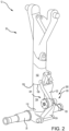
FIG. 2 illustrates a landing gear with the shock strut assembly, in accordance with various embodiments; -
FIG. 3 illustrates a cross-sectional view of a shimmy damper assembly, in accordance with various embodiments; and -
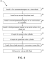
FIG. 4 illustrates a method of manufacturing a shimmy damper assembly, in accordance with various embodiments. - All ranges and ratio limits disclosed herein may be combined. It is to be understood that unless specifically stated otherwise, references to "a," "an," and/or "the" may include one or more than one and that reference to an item in the singular may also include the item in the plural.
- The detailed description of exemplary embodiments herein makes reference to the accompanying drawings, which show exemplary embodiments by way of illustration. While these exemplary embodiments are described in sufficient detail to enable those skilled in the art to practice the exemplary embodiments of the disclosure, it should be understood that other embodiments may be realized and that logical changes and adaptations in design and construction may be made in accordance with this disclosure and the teachings herein. Thus, the detailed description herein is presented for purposes of illustration only and not limitation. The steps recited in any of the method or process descriptions may be executed in any order and are not necessarily limited to the order presented. Furthermore, any reference to singular includes plural embodiments, and any reference to more than one component or step may include a singular embodiment or step. Also, any reference to attached, fixed, connected or the like may include permanent, removable, temporary, partial, full and/or any other possible attachment option. Additionally, any reference to without contact (or similar phrases) may also include reduced contact or minimal contact.
- Disclosed herein is a shimmy damper assembly for an aircraft landing gear. In accordance with various embodiments, the shock strut assembly includes a damper system operably coupled between the strut piston and the strut cylinder of the shock strut assembly. The damper system is configured to limit or eliminate shimmy during a landing event. "Shimmy," as referred to herein includes side to side oscillations perpendicular to a direction of travel for an aircraft of the landing gear due to structural vibrations and/or tire forces. Shimmy may reduce a stability of the landing gear over time and cause additional fatigue to a landing gear structure. In accordance with various embodiments, the damper system includes various permanent magnets and a magneto rheological fluid. In this regard, the damper system disclosed herein is a passive damper system for reducing and/or eliminating shimmy, in accordance with various embodiments.
- With reference to
FIG. 1 , anaircraft 10 is illustrated. In accordance with various embodiments,aircraft 10 may include landing gear such as left (or first)landing gear 12, right (or second)landing gear 14, and nose (or third)landing gear 16.Left landing gear 12,right landing gear 14, andnose landing gear 16 may generally supportaircraft 10 whenaircraft 10 is not flying, allowingaircraft 10 to taxi, take off, and land without damage.Left landing gear 12 may include ashock strut assembly 30 and a pair ofwheels 15 coupled by anaxle 20.Right landing gear 14 may include ashock strut assembly 32 and a pair ofwheels 17 coupled by anaxle 22.Nose landing gear 16 may include a shock strut assembly 34 and a pair ofnose wheels 19 coupled by anaxle 24. In various embodiments,nose wheels 19 may differ frommain wheels 15 andmain wheel 17 in that thenose wheels 19 may not include a brake. Whileleft landing gear 12,right landing gear 14, andnose landing gear 16 are illustrated as each having two wheels, it should be understood that the shock strut assemblies described herein may be used with landing gear having any number and/or configuration of wheels. - When supporting
aircraft 10 onground surface 11, the weight ofaircraft 10 may causeshock strut assemblies aircraft 10, the shock strut assemblies compress, thereby decreasing a stroke length of the shock strut assembly and absorbing the kinetic energy of the aircraft. - With reference to
FIG. 2 , a perspective view ofleft landing gear 12 is illustrated withshock strut assembly 30, in accordance with various embodiments.Shock strut assembly 30 may include astrut cylinder 102 and astrut piston 104.Axle 20 is coupled to anend 110 ofstrut piston 104 that isopposite strut cylinder 102.Strut piston 104 is telescopically coupled to strutcylinder 102. In this regard,strut piston 104 is configured to telescope relative to strutcylinder 102, thereby causingshock strut assembly 30 to absorb and damp loads imposed onleft landing gear 12. Stated differently,strut piston 104 translates in and outstrut cylinder 102. In various embodiments, fluid including hydraulic fluid, oil, and/or gas, such as nitrogen, may be located within an internal cavity ofstrut cylinder 102. The internal cavity ofstrut cylinder 102 may consist of a single cavity or separate cavities containing one or more different fluids within the cavities.Strut piston 104 translating relative to strutcylinder 102 may change the internal cavity pressure ofstrut cylinder 102 and/or may cause fluid to flow in and outshock strut assembly 30. -
Strut piston 104 extends fromstrut cylinder 102 by a length. In accordance with various embodiments, asshock strut assembly 30 compresses (i.e., asstrut piston 104 translates into strut cylinder 102), the length decreases. Conversely, asshock strut assembly 30 decompresses (i.e., asstrut piston 104 translates out strut cylinder 102), the length increases. In various embodiments, the length corresponds to a distance betweenaxle 20 and alower surface 108 ofstrut cylinder 102.Lower surface 108 ofstrut cylinder 102 defines apiston opening 109, instrut cylinder 102, through whichstrut piston 104 translates. - In various embodiments,
shock strut assembly 30 may include atorque link 120 coupled to thestrut cylinder 102 andstrut piston 104.Torque link 120 provides torsion stiffness forleft landing gear 12 and decreases rotation ofstrut piston 104 relative to strutcylinder 102. In various embodiments,torque link 120 may be coupled to thestrut cylinder 102 andaxle 20.Torque link 120 includes an upper (or first)arm 122 and a lower (or second)arm 124.Upper arm 122 may be coupled to strutcylinder 102.Lower arm 124 may be coupled to strutpiston 104 and/or toaxle 20.Upper arm 122 is pivotably coupled tolower arm 124 via a damper piston 126 (e.g., an apex pin).Upper arm 122 andlower arm 124 may pivot relative to one another and aboutdamper piston 126. For example,upper arm 122 andlower arm 124 may pivot relative to one another and aboutdamper piston 126 in response to translation of strut piston in and outstrut cylinder 102. Stated differently, pivot joint 126 is configured to allowupper arm 122 andlower arm 124 to rotate relative to one asstrut piston 104 telescopes relative to (i.e., translates in and out)strut cylinder 102. In various embodiments,shock strut assembly 30 may be part of an articulated landing gear. In this regard, a torque link, similar totorque link 120, may be pivotably coupled between shock strut assembly 30 (e.g., strut cylinder 102) and aircraft 10 (with momentary reference toFIG. 1 ). - In various embodiments, a
shimmy damper system 301 is integrated within thetorque link 120. In this regard, ashimmy damper assembly 300 may be located at the pivot joint of theupper arm 122 and thelower arm 124 as described further herein. In this regard, theshimmy damper assembly 300 is configured to reduce horizontal rotation or "shimmy" ofaxle 20. As used herein, "horizontal rotation" ofaxle 20 refers to rotation ofaxle 20 about an axis that is perpendicular to the axis of rotation ofwheels 15 and parallel to the direction that strutpiston 104 telescopes. - Referring now to
FIG. 3 , a cross sectional view of a portion of theshimmy damper assembly 300 with theshimmy damper system 301 is illustrated, in accordance with various embodiments. In various embodiments, shimmydamper assembly 300 comprises adamper piston 126 and ashimmy cylinder assembly 320. Thedamper piston 126 comprises apiston rod 312 and apiston head 314. - In various embodiments, the
piston head 314 comprises a firstpermanent magnet 316 of theshimmy damper system 301. The permanent magnet comprises a north seeking ("N")pole 317 and a south seeking ("S")pole 315. In various embodiments, the firstpermanent magnet 316 may be coupled to thepiston head 314 or be integral with thepiston head 314. The present disclosure is not limited in this regard. For example, thepiston head 314 may be magnetized to form theN pole 317 and theS pole 315, in accordance with various embodiments. - In various embodiments, the
shimmy cylinder assembly 320 comprises ashimmy cylinder 322 and agland nut 324. Theshimmy cylinder 322 is configured to be coupled to thegland nut 324 to form acavity 328 therein. Theshimmy cylinder assembly 320 further comprises a secondpermanent magnet 325 and a thirdpermanent magnet 327. The secondpermanent magnet 325 may comprise an S pole at least partially defining acavity 328. The thirdpermanent magnet 327 may comprise an N pole at least partially defining thecavity 328. In various embodiments, the thirdpermanent magnet 327 may be coupled to thegland nut 324 and the secondpermanent magnet 325 may be coupled to theshimmy cylinder 322. In various embodiments, the thirdpermanent magnet 327 may be integral with thegland nut 324 and the secondpermanent magnet 325 may be coupled to theshimmy cylinder 322. For example, an axial surface of thegland nut 324 and an axial surface of theshimmy cylinder 322 may be magnetized to form opposingpermanent magnets - In various embodiments, the third
permanent magnet 327 is spaced apart axially from theN pole 317 of the firstpermanent magnet 316, which is spaced apart axially from theS pole 315 of the firstpermanent magnet 316, which is spaced apart axially from the secondpermanent magnet 325. Although described as having the N Pole of the thirdpermanent magnet 327 disposed on thegland nut 324 and the S pole of the secondpermanent magnet 325 disposed on theshimmy cylinder 322, the present disclosure is not limited in this regard. For example, the N Pole of the thirdpermanent magnet 327 may be oriented into thecavity 328 and the S pole of the secondpermanent magnet 325 may oriented into thecavity 328 as long as theN pole 317 of the firstpermanent magnet 316 is disposed between the N pole of the thirdpermanent magnet 327 and theS pole 315 and theS pole 315 is disposed between the S pole of the secondpermanent magnet 325 and theN pole 317. In this regard, thepermanent magnets - The
cavity 328 is defined axially (i.e., along an axis of a centerline of theshimmy cylinder 322 or the Y-direction) between the N pole of the thirdpermanent magnet 327 and the S pole of the secondpermanent magnet 325. Thecavity 328 is defined radially between a radially outer surface of thepiston rod 312 and a radially inner surface of theshimmy cylinder 322 and thegland nut 324. - In various embodiments, a magnetorheological (MR)
fluid 329 is disposed within thecavity 328. TheMR fluid 329 is a "smart fluid" that, when subjected to a magnet field, increases in apparent viscosity. In this regard, the closer theN pole 317 off the firstpermanent magnet 316 and the N pole of the thirdpermanent magnet 327 become, the greater the viscosity of theMR fluid 329. Similarly, the closer theS pole 315 of the firstpermanent magnet 316 and the S pole of the secondpermanent magnet 325 become, the greater the viscosity of theMR fluid 329. Thus, theshimmy damper system 301 provides a variable damping within theshimmy damper system 301. - In various embodiments, the
piston head 314 further comprises anorifice 318 disposed axially therethrough. In various embodiments, thepiston head 314 may comprise a plurality of theorifice 318 disposed circumferentially about thepiston head 314. Any number oforifices 318 are within the scope of this disclosure. For example, the piston head may comprise two of theorifice 318, four of theorifice 318, eight of theorifice 318, or the like. In various embodiments, anannular orifice 340 may be defined between a radially outer surface ofpiston head 314 and a radially inner surface of theshimmy cylinder 322 and thegland nut 324. In this regard, as the piston head travels axially towards either the S pole of the secondpermanent magnet 325 or the N pole of the thirdpermanent magnet 327, the viscosity of theMR fluid 329 increases, the MR fluid travels through theorifice 318 and/or theannular orifice 340, thus resisting movement of thedamper piston 126 and damping thedamper piston 126, in accordance with various embodiments. - In various embodiments, the
piston head 314 may comprise a cap disposed thereon. In this regard, the cap may prevent contact between theMR fluid 329 and thepiston head 314. - In various embodiments, the
shimmy damper assembly 300 further comprises anupper arm 122 and alower arm 124. Theupper arm 122 is spaced apart axially (i.e., in the Y-direction) from thelower arm 124. Thus, a gap between theupper arm 122 and thelower arm 124 provided at an apex joint facilitates operation of theshimmy damper system 301, in accordance with various embodiments. - In various embodiments, the
shimmy damper system 301 is further configured to provide self-centering of thepiston head 314. For example, whenpiston head 314 travels towards the N pole of the thirdpermanent magnet 327, thepiston head 314 is repelled by an opposing force back towards a neutral position. Similarly, in response to thepiston head 314 traveling towards the S pole of the secondpermanent magnet 325, thepiston head 314 is repelled by an opposing force back towards the neutral position. Thus, springs and/or washers may be removed from theshimmy damper system 301, in accordance with various embodiments. - In various embodiments, a dynamic seal may be disposed radially between a radially inner surface of the
gland nut 324 and a radially outer surface of thepiston rod 312 and axially along the radially inner surface of thegland nut 324. Similarly, a dynamic seal may be disposed radially between a radially inner surface of theshimmy cylinder 322 and the radially outer surface of thepiston rod 312 and axially along the radially inner surface of theshimmy cylinder 322. In this regard, thepiston rod 312 may travel axially relative to theshimmy cylinder assembly 320 and maintain fluid isolation between theMR fluid 329 and an external environment. - Referring now to
FIGs. 3 and4 , a method 400 (FIG. 4 ) of manufacturing ashimmy damper system 301 for ashimmy damper assembly 300 fromFIG. 3 is illustrated, in accordance with various embodiments. Themethod 400 comprises installing a firstpermanent magnet 316 on a piston head 314 (step 402). The firstpermanent magnet 316 may be coupled to thepiston head 314 or thepiston head 314 may be magnetized, in accordance with various embodiments. - The
method 400 may further comprise installing a cap around thepiston head 314 to fluidly isolate thepiston head 314 from an MR fluid (step 404). Themethod 400 further comprises installing a second permanent magnet (e.g., second permanent magnet 325) on an axial surface of a shimmy cylinder 322 (step 406). Themethod 400 further comprises installing a third permanent magnet (e.g., third permanent magnet 327) on an axial surface of a gland nut 324 (step 408). The permanent magnets may be oriented in a manner to form a Halbach array as described previously herein. - The
method 400 further comprises coupling adamper piston 126 including thepiston head 314 and apiston rod 312 to the shimmy cylinder 322 (step 410). Themethod 400 further comprises coupling thegland nut 324 to theshimmy cylinder 322 to form acavity 328 therein (step 412). Themethod 400 further comprises coupling theshimmy cylinder assembly 320 to an upper arm 122 (step 414). Themethod 400 further comprises filling thecavity 328 with anMR fluid 329. The MR fluid may be disposed through an aperture in theshimmy cylinder assembly 320 that is sealed after filling thecavity 328, in accordance with various embodiments. - Benefits and other advantages have been described herein with regard to specific embodiments. Furthermore, the connecting lines shown in the various figures contained herein are intended to represent exemplary functional relationships and/or physical couplings between the various elements. It should be noted that many alternative or additional functional relationships or physical connections may be present in a practical system. However, the benefits, advantages, and any elements that may cause any benefit or advantage to occur or become more pronounced are not to be construed as critical, required, or essential features or elements of the disclosure. The scope of the disclosure is accordingly to be limited by nothing other than the appended claims, in which reference to an element in the singular is not intended to mean "one and only one" unless explicitly so stated, but rather "one or more." Moreover, where a phrase similar to "at least one of A, B, or C" is used in the claims, it is intended that the phrase be interpreted to mean that A alone may be present in an embodiment, B alone may be present in an embodiment, C alone may be present in an embodiment, or that any combination of the elements A, B and C may be present in a single embodiment; for example, A and B, A and C, B and C, or A and B and C.
- Systems, methods, and apparatus are provided herein. In the detailed description herein, references to "various embodiments", "one embodiment", "an embodiment", "an example embodiment", etc., indicate that the embodiment described may include a particular feature, structure, or characteristic, but every embodiment may not necessarily include the particular feature, structure, or characteristic. Moreover, such phrases are not necessarily referring to the same embodiment. Further, when a particular feature, structure, or characteristic is described in connection with an embodiment, it is submitted that it is within the knowledge of one skilled in the art to affect such feature, structure, or characteristic in connection with other embodiments whether or not explicitly described. After reading the description, it will be apparent to one skilled in the relevant art(s) how to implement the disclosure in alternative embodiments.
- Furthermore, no element, component, or method step in the present disclosure is intended to be dedicated to the public regardless of whether the element, component, or method step is explicitly recited in the claims. As used herein, the terms "comprises", "comprising", or any other variation thereof, are intended to cover a non-exclusive inclusion, such that a process, method, article, or apparatus that comprises a list of elements does not include only those elements but may include other elements not expressly listed or inherent to such process, method, article, or apparatus.
Claims (15)
- A shimmy damper assembly (300), comprising:a damper piston (126) including a piston head (314), the piston head comprising a first permanent magnet (316),a shimmy cylinder (322) including a second permanent magnet (325) disposed on an axial surface of the shimmy cylinder (322), anda gland nut (324) coupled to the shimmy cylinder (322), the gland nut (324) including a third permanent magnet (327) spaced apart axially from the second permanent magnet (325), the piston head (314) disposed between the first permanent magnet (316) and the second permanent magnet (325).
- The shimmy damper assembly of claim 1, further comprising a magnetorheological, MR, fluid (329) disposed in a cavity (328) of a shimmy cylinder assembly (300), the shimmy cylinder assembly including the shimmy cylinder (322) and the gland nut (324).
- The shimmy damper assembly of claim 1, further comprising a cavity (328) of a shimmy cylinder assembly (300), the shimmy cylinder assembly including the shimmy cylinder (322) and the gland nut (324), wherein the cavity (328) is defined radially between a radially outer surface of the damper piston (126) and a radially inner surface of the shimmy cylinder (322) and the gland nut (324), and preferably wherein the cavity (328) is defined axially between the second permanent magnet (325) and the third permanent magnet (327).
- The shimmy damper assembly of any preceding claim, wherein the first permanent magnet (316), the second permanent magnet (325), and the third permanent magnet (327) are oriented in a manner to form a Halbach array.
- The shimmy damper assembly of any preceding claim, wherein the first permanent magnet (316), the second permanent magnet (325), and the third permanent magnet (327) each comprise a first pole and a second pole, and wherein the first permanent magnet (316) comprises the second pole spaced apart axially proximate the second pole of the second permanent magnet (325), and preferably wherein the first pole of the first permanent magnet (316) is disposed on a first axial surface of the piston head (126) and the second pole of the first permanent magnet (316) is disposed on a second axial surface of the piston head (126), the first axial surface disposed axially opposite the second axial surface.
- The shimmy damper assembly of any preceding claim, further comprising an orifice (318) disposed axially through the piston head (126).
- The shimmy damper assembly of any preceding claim, further comprising an annular orifice (340) defined between a radially outer surface of the piston head and a radially inner surface of the gland nut (324) and the shimmy cylinder (322).
- A landing gear (12, 14, 16), comprising:an axle (20, 22, 24) configured to support a tire; anda shock strut assembly (30, 32, 34) coupled to the axle, the shock strut assembly including:a strut cylinder (102);a strut piston (104) configured to telescope relative to the strut cylinder; anda shimmy damper system (301), comprising:a damper piston (126) having a piston rod (312) and a piston head (314), the piston head including a first permanent magnet (316) disposed thereon, anda shimmy cylinder assembly (300) at least partially defining a cavity (328), the shimmy cylinder assembly having a second permanent magnet (325) and a third permanent magnet (327) disposed within the cavity (328), wherein the first permanent magnet (316), the second permanent magnet (325) and the third permanent magnet (327) are oriented in a manner to form a Halbach array.
- The landing gear of claim 8, wherein the shimmy damper system (301) further comprises a magnetorheological, MR, fluid (329) disposed in the cavity of the shimmy cylinder assembly.
- The landing gear of claim 8 or 9, wherein the piston head (126) comprises an orifice (318) disposed axially through the piston head.
- The landing gear of any of claims 8-10, wherein the shimmy damper system further comprises an annular orifice (340) defined between a radially outer surface of the piston head (126) and a radially inner surface of the shimmy cylinder assembly (300); and/orwherein the piston head (126) is configured to self-center within the cavity (328) in response to traveling axially towards one of the second permanent magnet (325) and the third permanent magnet (327); and/orwherein the shimmy damper system is configured to passively dampen the damper piston.
- The landing gear of any of claims 8-11, further comprising a torque link (120) coupled to the shimmy cylinder assembly (300), and preferably further comprising a second torque link spaced apart axially from the torque link.
- A method of manufacturing a shimmy damper system, the method comprising:installing a permanent magnet on a piston head of a piston;installing a second permanent magnet on a shimmy cylinder of a shimmy cylinder assembly;installing a third permanent magnet on a gland nut of the shimmy cylinder assembly; andoperably coupling the shimmy cylinder assembly to the piston, the shimmy cylinder assembly at least partially defining a cavity therein, the piston head disposed within the cavity.
- The method of claim 13, further comprising filling the cavity with a magnetorheological (MR) fluid.
- The method of claim 13 or 14, further comprising sealing the cavity from an external environment.
Applications Claiming Priority (2)
| Application Number | Priority Date | Filing Date | Title |
|---|---|---|---|
| IN202141058202 | 2021-12-14 | ||
| US17/673,941 US12384530B2 (en) | 2021-12-14 | 2022-02-17 | Self-sustaining shimmy damper system for landing gear shock strut assemblies |
Publications (1)
| Publication Number | Publication Date |
|---|---|
| EP4198334A1 true EP4198334A1 (en) | 2023-06-21 |
Family
ID=84369625
Family Applications (1)
| Application Number | Title | Priority Date | Filing Date |
|---|---|---|---|
| EP22210937.3A Pending EP4198334A1 (en) | 2021-12-14 | 2022-12-01 | Self-sustaining shimmy damper system for landing gear shock strut assemblies |
Country Status (2)
| Country | Link |
|---|---|
| EP (1) | EP4198334A1 (en) |
| CA (1) | CA3181180A1 (en) |
Citations (3)
| Publication number | Priority date | Publication date | Assignee | Title |
|---|---|---|---|---|
| DE102011113918A1 (en) * | 2011-09-21 | 2013-03-21 | Patrik Gallinnis | Shock absorbing property generating device i.e. magnetic field shock absorber for car, has permanent magnets whose magnetic fields cause compensation of active physical impact force, and piston implementing axial movement of piston rod |
| CN108980259A (en) * | 2018-07-10 | 2018-12-11 | 杭州电子科技大学 | A kind of adaptive shimmy-damper suitable for electric car |
| EP3882137A1 (en) * | 2020-03-19 | 2021-09-22 | Goodrich Corporation | Magnetic self-centering shimmy damper |
-
2022
- 2022-11-03 CA CA3181180A patent/CA3181180A1/en active Pending
- 2022-12-01 EP EP22210937.3A patent/EP4198334A1/en active Pending
Patent Citations (3)
| Publication number | Priority date | Publication date | Assignee | Title |
|---|---|---|---|---|
| DE102011113918A1 (en) * | 2011-09-21 | 2013-03-21 | Patrik Gallinnis | Shock absorbing property generating device i.e. magnetic field shock absorber for car, has permanent magnets whose magnetic fields cause compensation of active physical impact force, and piston implementing axial movement of piston rod |
| CN108980259A (en) * | 2018-07-10 | 2018-12-11 | 杭州电子科技大学 | A kind of adaptive shimmy-damper suitable for electric car |
| EP3882137A1 (en) * | 2020-03-19 | 2021-09-22 | Goodrich Corporation | Magnetic self-centering shimmy damper |
Also Published As
| Publication number | Publication date |
|---|---|
| CA3181180A1 (en) | 2023-06-14 |
Similar Documents
| Publication | Publication Date | Title |
|---|---|---|
| EP2397407B1 (en) | Torque link with shimmy damper | |
| US6926500B2 (en) | Fluid inertia drag damper for rotary wing aircraft rotor | |
| EP3498601A1 (en) | Latch assembly for shock strut | |
| US12384530B2 (en) | Self-sustaining shimmy damper system for landing gear shock strut assemblies | |
| EP3118479B1 (en) | Aircraft landing gear shock absorber | |
| EP3882137B1 (en) | Magnetic self-centering shimmy damper | |
| US12552522B2 (en) | Shock strut variable-area metering unit | |
| US9061759B2 (en) | Cam-operated bi-directional shock absorber damper | |
| US10589848B2 (en) | Landing-gear assembly for an aircraft, the landing-gear assembly including a secondary shimmy damper | |
| CN109229346B (en) | Buffer suitable for miniature unmanned vehicles oil gas shock attenuation formula undercarriage | |
| CA3181180A1 (en) | Self-sustaining shimmy damper system for landing gear shock strut assemblies | |
| EP3418190B1 (en) | Semi cantilevered landing gear actuated by an external articulating load damper for improved take-off | |
| US12404015B2 (en) | Energy absorption system for landing gear | |
| BR102022025025A2 (en) | SHIMMY DAMPER VIBRATION DAMPER ASSEMBLY, LANDING GEAR, AND METHOD OF MANUFACTURING A SHIMMY DAMPER VIBRATION DAMPER SYSTEM | |
| CN108820191B (en) | Landing gear shock absorption structure for solar unmanned aerial vehicle in near space and landing gear | |
| US11498666B2 (en) | Shock strut assemblies for landing gear | |
| EP3696431B1 (en) | Composite shock strut cylinder with integral metallic lower bearing carrier and sleeve | |
| EP4474673A1 (en) | Energy absorption system for landing gear | |
| US11608163B2 (en) | Rebound valve systems and methods | |
| EP3486521B1 (en) | Shock strut with integral shrink piston actuator | |
| EP3948010B1 (en) | Vibration damper and/or absorber | |
| CN207059769U (en) | Power transmission shaft torsional vibration damper and vehicle | |
| CN120685274A (en) | A composite support system for resonance testing |
Legal Events
| Date | Code | Title | Description |
|---|---|---|---|
| PUAI | Public reference made under article 153(3) epc to a published international application that has entered the european phase |
Free format text: ORIGINAL CODE: 0009012 |
|
| STAA | Information on the status of an ep patent application or granted ep patent |
Free format text: STATUS: THE APPLICATION HAS BEEN PUBLISHED |
|
| AK | Designated contracting states |
Kind code of ref document: A1 Designated state(s): AL AT BE BG CH CY CZ DE DK EE ES FI FR GB GR HR HU IE IS IT LI LT LU LV MC ME MK MT NL NO PL PT RO RS SE SI SK SM TR |
|
| P01 | Opt-out of the competence of the unified patent court (upc) registered |
Effective date: 20230922 |
|
| STAA | Information on the status of an ep patent application or granted ep patent |
Free format text: STATUS: REQUEST FOR EXAMINATION WAS MADE |
|
| 17P | Request for examination filed |
Effective date: 20231205 |
|
| RBV | Designated contracting states (corrected) |
Designated state(s): AL AT BE BG CH CY CZ DE DK EE ES FI FR GB GR HR HU IE IS IT LI LT LU LV MC ME MK MT NL NO PL PT RO RS SE SI SK SM TR |