EP3418190B1 - Semi cantilevered landing gear actuated by an external articulating load damper for improved take-off - Google Patents
Semi cantilevered landing gear actuated by an external articulating load damper for improved take-off Download PDFInfo
- Publication number
- EP3418190B1 EP3418190B1 EP18179663.2A EP18179663A EP3418190B1 EP 3418190 B1 EP3418190 B1 EP 3418190B1 EP 18179663 A EP18179663 A EP 18179663A EP 3418190 B1 EP3418190 B1 EP 3418190B1
- Authority
- EP
- European Patent Office
- Prior art keywords
- landing gear
- load damper
- strut
- link
- lever
- Prior art date
- Legal status (The legal status is an assumption and is not a legal conclusion. Google has not performed a legal analysis and makes no representation as to the accuracy of the status listed.)
- Active
Links
Images


Classifications
-
- B—PERFORMING OPERATIONS; TRANSPORTING
- B64—AIRCRAFT; AVIATION; COSMONAUTICS
- B64C—AEROPLANES; HELICOPTERS
- B64C25/00—Alighting gear
- B64C25/32—Alighting gear characterised by elements which contact the ground or similar surface
- B64C25/58—Arrangements or adaptations of shock-absorbers or springs
- B64C25/60—Oleo legs
-
- B—PERFORMING OPERATIONS; TRANSPORTING
- B64—AIRCRAFT; AVIATION; COSMONAUTICS
- B64C—AEROPLANES; HELICOPTERS
- B64C25/00—Alighting gear
- B64C25/001—Devices not provided for in the groups B64C25/02 - B64C25/68
- B64C2025/008—Comprising means for modifying their length, e.g. for kneeling, for jumping, or for leveling the aircraft
Definitions
- the present disclosure relates to aircraft landing gear, and more particularly, to systems and methods for extending landing gear.
- Pitch rotation of an airplane is limited by the length of the shock strut.
- the shock strut may be lengthened to achieve a greater angle of attack for the airplane during initial rotation of the aircraft during take-off.
- US 2013/119196 A1 describes a hydraulic strut assembly for a semi-levered landing gear.
- a landing gear arrangement is defined in claim 1, comprising a lever configured to be coupled between an axle and a strut piston of a shock strut, a load damper configured to be externally coupled between the shock strut and the lever, wherein the load damper is configured to increase a length of the landing gear arrangement in response to an extension force of the load damper increasing above a ground force reacted through the landing gear arrangement.
- the landing gear arrangement further comprises a first link configured to be rotatably coupled to a second link, wherein the first link is configured to be coupled to the load damper and the second link is configured to be coupled to the lever.
- the lever is configured to rotate with respect to the strut piston.
- the first link comprises a first attachment point whereby the first link is configured to be rotatably coupled to a strut cylinder of the shock strut, a second attachment point whereby the first link is configured to be rotatably coupled to the load damper, and a third attachment point whereby the first link is configured to be rotatably coupled to the second link.
- the load damper comprises a load damper cylinder, and a load damper piston operatively coupled to the load damper cylinder.
- the load damper passively transmits the extension force to the lever.
- the load damper is mechanically coupled to the strut piston.
- the load damper is mechanically coupled to the strut cylinder.
- the landing gear arrangement further comprises a first link, and a second link rotatably coupled to the first link, wherein the first link is coupled to the load damper and the second link is coupled to the lever.
- the first link comprises a first attachment point whereby the first link is rotatably coupled to the strut cylinder, a second attachment point whereby the first link is rotatably coupled to the load damper, and a third attachment point whereby the first link is rotatably coupled to the second link.
- the landing gear arrangement further comprises an axle mounted to the lever.
- the lever rotates away from the second end in response to the load damper extending.
- the lever engages the second end in response to the load damper compressing.
- a method for extending a landing gear for an airplane is disclosed in claim 14.
- the method further comprises rotating a lever in response to the load damper being extended.
- the load damper extends in response to the ground force decreasing below an extension force of the load damper.
- Pitch rotation of an airplane may be limited by the length of the shock strut.
- the shock strut may be lengthened to achieve a greater angle of attack for the airplane during initial rotation of the aircraft during take-off.
- An external articulating load damper as disclosed herein, may passively cause a lever to rotate with respect to a strut piston to extend a landing gear during take-off.
- the load damper may comprise a pressure vessel defined by a cylinder and a piston configured to retract and extend with respect to the cylinder.
- the piston may extend from the cylinder in response to an extension force of the load damper being greater than a ground force on the landing gear, causing the total length of the landing gear to increase and allowing greater airplane pitch rotation during take-off and thereby preventing tail-strike.
- the load damper may further dampen ground forces during take-off and/or landing.
- the external articulating load damper as disclosed herein, may comprise a passive system, thereby minimizing part count, reducing total weight of a landing gear arrangement, and/or increasing robustness of the landing gear.
- an aircraft 10 in accordance with various embodiments may include landing gear such as landing gear 12, landing gear 14 and landing gear 16.
- Landing gear 12, landing gear 14 and landing gear 16 may generally support aircraft 10 when aircraft is not flying, allowing aircraft 10 to taxi, take off and land without damage.
- Landing gear 12 may include shock strut 30 and wheel assembly 20.
- Landing gear 14 may include shock strut 32 and wheel assembly 22.
- Landing gear 16 may include shock strut 34 and nose wheel assembly 24.
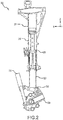
- Landing gear arrangement 200 is illustrated, in accordance with various examples (not forming part of the claimed invention).
- Landing gear 12 and landing gear 14 of FIG. 1 may be similar to landing gear arrangement 200.
- Landing gear arrangement 200 may comprise a shock strut 201.
- Shock strut 201 may comprise a strut cylinder 210 and a strut piston 220.
- Strut piston 220 may be operatively coupled to strut cylinder 210.
- Strut piston 220 may comprise a first end 221 disposed within strut cylinder 210 and a second end 222 extending from strut cylinder 210.
- Strut cylinder 210 may be configured to receive strut piston 220 in a manner that allows the two components to telescope together and absorb and dampen forces transmitted thereto.
- a liquid such as a hydraulic fluid and/or oil may be located within strut cylinder 210.
- a gas such as nitrogen or air, may be located within strut cylinder 210.
- Strut cylinder 210 and strut piston 220 may, for example, be configured to seal such that fluid contained within strut cylinder 210 is prevented from leaking as strut piston 220 translates relative to strut cylinder 210.
- load damper 250 may comprise a single-stage shock absorber. It is contemplated herein that components such as a metering pin, check valve, or other components associated with dampers may be used within load damper 250.
- Load damper 250 may comprise a pneumatic shock absorber.
- landing gear arrangement 200 may comprise a lever 230 and an external articulating load damper (load damper) 250.
- Lever 230 may be rotatably coupled to strut piston 220.
- lever 230 may be configured to rotate with respect to strut piston 220.
- Strut piston 220 may comprise a first lug 224, with momentary reference to FIG. 3A , whereby lever 230 is rotatably coupled to strut piston 220.
- Load damper 250 may be located externally from strut piston 220. In this regard, load damper 250 may be externally coupled between shock strut 201 and lever 230.
- load damper 250 may be coupled between strut piston 220 and lever 230.
- Strut piston 220 may comprise a second lug 226, with momentary reference to FIG. 3A , whereby load damper 250 is rotatably coupled to strut piston 220.
- load damper 250 may comprise a damper cylinder 252 and a damper piston 254.
- Damper piston 254 may be operatively coupled to damper cylinder 252.
- Damper cylinder 252 may be configured to receive damper piston 254 in a manner that allows the two components to telescope together and absorb and dampen forces transmitted thereto.
- a liquid such as an oil for example, may be located within damper cylinder 252.
- a gas such as nitrogen or air, may be located within damper cylinder 252.
- Damper cylinder 252 and damper piston 254 may, for example, be configured to seal such that fluid contained within damper cylinder 252 is prevented from leaking as damper piston 254 translates relative to damper cylinder 252.
- Load damper 250 may comprise a passive system, as described herein.
- load damper 250 and/or lever 230 may be made from a metal material, such as stainless steel for example.
- FIG. 3A depicts landing gear arrangement 200 in a static position, such as when an aircraft is on the ground, for example.
- FIG. 5A depicts an aircraft 500 in a static position, not moving relative to the ground.
- shock strut 201 may be in a compressed position when aircraft 500 is in the static position.
- An axle 260 may be mounted to lever 230.
- One or more tires 555 may be mounted to axle 260.
- a ground force 590 may be transmitted from the ground, through tire 555, through axle 260, into lever 230 and into both shock strut 201 and load damper 250. Stated differently, ground force 590 may be reacted through landing gear arrangement 200.
- Load damper 250 may transmit a force (also referred to herein as an extension force) 290 to lever 230.
- the extension force 290 may be a product of a pressure of a fluid within load damper 250 and a surface area acted upon by said pressurized fluid of damper piston 254.
- ground force 590 may be greater than extension force 290, causing load damper 250 to compress.
- lever 230 may be rotated against strut piston 220. Stated differently, lever 230 may engage strut piston 220 at contact surface 232. The length L1 of landing gear arrangement 200 may decrease in response to lever 230 rotating against strut piston 220.
- FIG. 3B depicts landing gear arrangement 200 in a take-off position, such as when an aircraft takes off for flight, for example.
- FIG. 5B depicts an aircraft 500 in a take-off position, rotated relative to the ground.
- shock strut 201 may be in an extended position when aircraft 500 is in the take-off position.
- ground force 591 may be transmitted from the ground, through tire 555, through axle 260, into lever 230 and into both shock strut 201 and load damper 250. Stated differently, ground force 591 may be reacted through landing gear arrangement 200.
- Load damper 250 may transmit a force (also referred to herein as an extension force) 291 to lever 230.
- aircraft 500 may generate a lift force 595. Therefore, ground force 591 may decrease and ground force 591 may be less than extension force 291, allowing load damper 250 to extend.
- lever 230 In the take-off position, lever 230 may be rotated away from strut piston 220.
- the length L2 of landing gear arrangement 200 may increase in response to lever 230 rotating away from strut piston 220. Stated differently, length L2 may be greater than length L1.
- Axle 260 may move away from shock strut 201 in response to lever 230 rotating away from strut piston 220.
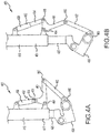
- Landing gear arrangement 400 may be similar to landing gear arrangement 200, with momentary reference to FIG. 3A and FIG. 3B , except that landing gear arrangement 400 further includes a linkage between load damper 450 and lever 430.
- the linkage may be capable of fitting between wheel assemblies located on either side of axle 460.
- landing gear arrangement 400 may include shock strut 401, lever 430, external articulating load damper (load damper) 450, first link 461, and second link 462.
- First link 461 may comprise a first attachment point 464 whereby first link 461 is rotatably coupled to strut cylinder 410.
- First link 461 may comprise a second attachment point 465 whereby first link 461 is rotatably coupled to load damper 450.
- First link 461 may comprise a third attachment point 466 whereby first link 461 is rotatably coupled to second link 462.
- Second link 462 may be rotatably coupled to lever 430.
- load damper may transmit an extension force into first link 461 which may cause first link 461 to rotate about first attachment point 464 with respect to strut cylinder 410, causing lever 430 to rotate away from strut piston 420.
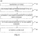
- Method 600 include generating a lift force (step 610).
- Method 600 includes decreasing a ground force in response to the lift force (step 620).
- Method 600 include extending a load damper in response to the ground force decreasing (step 630).
- Method 600 includes rotating a lever in response to the load damper extending (step 640).
- Method 600 includes extending a landing gear (step 650).
- step 610 may include generating a lift force 595.
- the lift force 595 may be generated by aircraft 500, such as via aerodynamic forces onto a wing of aircraft 500 for example.
- Step 620 may include decreasing ground force 590, such as decreasing from ground force 590 to ground force 591 for example, in response to lift force 595.
- Step 630 may include extending load damper 250 in response to ground force 591 being decreased.
- Step 640 may include rotating lever 230 in response to load damper 250 extending.
- Step 650 may include extending landing gear arrangement 200 (e.g., from length L1 to length L2) in response to the extension of load damper 250.
- Step 650 may include extending landing gear arrangement 200 (e.g., from length L1 to length L2) in response to the lever 230 rotating.
- any of the method or process descriptions may be executed in any order and are not necessarily limited to the order presented.
- any reference to singular includes plural embodiments, and any reference to more than one component or step may include a singular embodiment or step.
- Elements and steps in the figures are illustrated for simplicity and clarity and have not necessarily been rendered according to any particular sequence. For example, steps that may be performed concurrently or in different order are illustrated in the figures to help to improve understanding of embodiments of the present disclosure.
- references to "one embodiment,” “an embodiment,” “various embodiments,” etc. indicate that the embodiment described may include a particular feature, structure, or characteristic, but every embodiment may not necessarily include the particular feature, structure, or characteristic. Moreover, such phrases are not necessarily referring to the same embodiment. Further, when a particular feature, structure, or characteristic is described in connection with an embodiment, it is submitted that it is within the knowledge of one skilled in the art to affect such feature, structure, or characteristic in connection with other embodiments whether or not explicitly described. After reading the description, it will be apparent to one skilled in the relevant art(s) how to implement the disclosure in alternative embodiments.
- the terms “comprises”, “comprising”, or any other variation thereof, are intended to cover a non-exclusive inclusion, such that a process, method, article, or apparatus that comprises a list of elements does not include only those elements but may include other elements not expressly listed or inherent to such process, method, article, or apparatus.
Description
- The present disclosure relates to aircraft landing gear, and more particularly, to systems and methods for extending landing gear.
- Pitch rotation of an airplane is limited by the length of the shock strut. The shock strut may be lengthened to achieve a greater angle of attack for the airplane during initial rotation of the aircraft during take-off.
US 2013/119196 A1 describes a hydraulic strut assembly for a semi-levered landing gear. - A landing gear arrangement is defined in claim 1, comprising a lever configured to be coupled between an axle and a strut piston of a shock strut, a load damper configured to be externally coupled between the shock strut and the lever, wherein the load damper is configured to increase a length of the landing gear arrangement in response to an extension force of the load damper increasing above a ground force reacted through the landing gear arrangement. The landing gear arrangement further comprises a first link configured to be rotatably coupled to a second link, wherein the first link is configured to be coupled to the load damper and the second link is configured to be coupled to the lever.
- In various embodiments, the lever is configured to rotate with respect to the strut piston.
- DELETED
- In various embodiments, the first link comprises a first attachment point whereby the first link is configured to be rotatably coupled to a strut cylinder of the shock strut, a second attachment point whereby the first link is configured to be rotatably coupled to the load damper, and a third attachment point whereby the first link is configured to be rotatably coupled to the second link.
- In various embodiments, the load damper comprises a load damper cylinder, and a load damper piston operatively coupled to the load damper cylinder.
- In various embodiments, the load damper passively transmits the extension force to the lever.
- In various embodiments, the load damper is mechanically coupled to the strut piston.
- In various embodiments, the load damper is mechanically coupled to the strut cylinder.
- In various embodiments, the landing gear arrangement further comprises a first link, and a second link rotatably coupled to the first link, wherein the first link is coupled to the load damper and the second link is coupled to the lever.
- In various embodiments, the first link comprises a first attachment point whereby the first link is rotatably coupled to the strut cylinder, a second attachment point whereby the first link is rotatably coupled to the load damper, and a third attachment point whereby the first link is rotatably coupled to the second link.
- In various embodiments, the landing gear arrangement further comprises an axle mounted to the lever.
- In various embodiments, the lever rotates away from the second end in response to the load damper extending.
- In various embodiments, the lever engages the second end in response to the load damper compressing.
- A method for extending a landing gear for an airplane is disclosed in
claim 14. - In various embodiments, the method further comprises rotating a lever in response to the load damper being extended.
- In various embodiments, the load damper extends in response to the ground force decreasing below an extension force of the load damper.
- The forgoing features and elements may be combined in various combinations without exclusivity, unless expressly indicated herein otherwise. These features and elements as well as the operation of the disclosed embodiments will become more apparent in light of the following description and accompanying drawings.
-
-
FIG. 1 illustrates an aircraft, in accordance with various embodiments; -
FIG. 2 illustrates a schematic view of a landing gear arrangement; -
FIG. 3A illustrates a schematic view of a landing gear arrangement in a static position; -
FIG. 3B illustrates a schematic view of a landing gear arrangement in a take-off position; -
FIG. 4A illustrates a schematic view of a landing gear arrangement having a linkage in a static position, in accordance with various embodiments; -
FIG. 4B illustrates a schematic view of a landing gear arrangement having a linkage in a take-off position, in accordance with various embodiments; -
FIG. 5A illustrates a schematic view of an aircraft having a landing gear arrangement in a static position, in accordance with various embodiments; -
FIG. 5B illustrates a schematic view of an aircraft having a landing gear arrangement in a take-off position, in accordance with various embodiments; and -
FIG. 6 illustrates a method for method for extending a landing gear, in accordance with various embodiments. - The subject matter of the present disclosure is particularly pointed out and distinctly claimed in the concluding portion of the specification. A more complete understanding of the present disclosure, however, may best be obtained by referring to the detailed description and claims when considered in connection with the drawing figures, wherein like numerals denote like elements.
- The detailed description of exemplary embodiments herein makes reference to the accompanying drawings, which show exemplary embodiments by way of illustration. While these exemplary embodiments are described in sufficient detail to enable those skilled in the art to practice the disclosure, it should be understood that other embodiments may be realized and that logical changes and adaptations in design and construction may be made in accordance with this disclosure and the teachings herein without departing from the scope of the disclosure. Thus, the detailed description herein is presented for purposes of illustration only and not of limitation.
- Pitch rotation of an airplane may be limited by the length of the shock strut. The shock strut may be lengthened to achieve a greater angle of attack for the airplane during initial rotation of the aircraft during take-off. An external articulating load damper, as disclosed herein, may passively cause a lever to rotate with respect to a strut piston to extend a landing gear during take-off. The load damper may comprise a pressure vessel defined by a cylinder and a piston configured to retract and extend with respect to the cylinder. The piston may extend from the cylinder in response to an extension force of the load damper being greater than a ground force on the landing gear, causing the total length of the landing gear to increase and allowing greater airplane pitch rotation during take-off and thereby preventing tail-strike. The load damper may further dampen ground forces during take-off and/or landing. The external articulating load damper, as disclosed herein, may comprise a passive system, thereby minimizing part count, reducing total weight of a landing gear arrangement, and/or increasing robustness of the landing gear.
- With reference to
FIG. 1 , anaircraft 10 in accordance with various embodiments may include landing gear such aslanding gear 12,landing gear 14 andlanding gear 16.Landing gear 12,landing gear 14 andlanding gear 16 may generally supportaircraft 10 when aircraft is not flying, allowingaircraft 10 to taxi, take off and land without damage.Landing gear 12 may includeshock strut 30 andwheel assembly 20.Landing gear 14 may includeshock strut 32 andwheel assembly 22.Landing gear 16 may includeshock strut 34 andnose wheel assembly 24. - With reference to
FIG. 2 , alanding gear arrangement 200 is illustrated, in accordance with various examples (not forming part of the claimed invention).Landing gear 12 andlanding gear 14 ofFIG. 1 may be similar tolanding gear arrangement 200.Landing gear arrangement 200 may comprise ashock strut 201.Shock strut 201 may comprise astrut cylinder 210 and astrut piston 220.Strut piston 220 may be operatively coupled tostrut cylinder 210.Strut piston 220 may comprise afirst end 221 disposed withinstrut cylinder 210 and asecond end 222 extending fromstrut cylinder 210.Strut cylinder 210 may be configured to receivestrut piston 220 in a manner that allows the two components to telescope together and absorb and dampen forces transmitted thereto. In various embodiments, a liquid, such as a hydraulic fluid and/or oil may be located withinstrut cylinder 210. Further, a gas, such as nitrogen or air, may be located withinstrut cylinder 210.Strut cylinder 210 andstrut piston 220 may, for example, be configured to seal such that fluid contained withinstrut cylinder 210 is prevented from leaking asstrut piston 220 translates relative to strutcylinder 210. In various embodiments,load damper 250 may comprise a single-stage shock absorber. It is contemplated herein that components such as a metering pin, check valve, or other components associated with dampers may be used withinload damper 250.Load damper 250 may comprise a pneumatic shock absorber. - In various embodiments,
landing gear arrangement 200 may comprise alever 230 and an external articulating load damper (load damper) 250.Lever 230 may be rotatably coupled to strutpiston 220. In this regard,lever 230 may be configured to rotate with respect to strutpiston 220.Strut piston 220 may comprise afirst lug 224, with momentary reference toFIG. 3A , wherebylever 230 is rotatably coupled to strutpiston 220.Load damper 250 may be located externally fromstrut piston 220. In this regard,load damper 250 may be externally coupled betweenshock strut 201 andlever 230. In various examples (not forming part of the claimed invention),load damper 250 may be coupled betweenstrut piston 220 andlever 230.Strut piston 220 may comprise asecond lug 226, with momentary reference toFIG. 3A , wherebyload damper 250 is rotatably coupled to strutpiston 220. - With combined reference to
FIG. 2 ,FIG. 3A, and FIG. 3B ,load damper 250 may comprise adamper cylinder 252 and adamper piston 254.Damper piston 254 may be operatively coupled todamper cylinder 252.Damper cylinder 252 may be configured to receivedamper piston 254 in a manner that allows the two components to telescope together and absorb and dampen forces transmitted thereto. In various embodiments, a liquid, such as an oil for example, may be located withindamper cylinder 252. Further, a gas, such as nitrogen or air, may be located withindamper cylinder 252.Damper cylinder 252 anddamper piston 254 may, for example, be configured to seal such that fluid contained withindamper cylinder 252 is prevented from leaking asdamper piston 254 translates relative todamper cylinder 252.Load damper 250 may comprise a passive system, as described herein. In various embodiments,load damper 250 and/orlever 230 may be made from a metal material, such as stainless steel for example. -
FIG. 3A depicts landinggear arrangement 200 in a static position, such as when an aircraft is on the ground, for example.FIG. 5A depicts anaircraft 500 in a static position, not moving relative to the ground. With combined reference toFIG. 3A andFIG. 5A ,shock strut 201 may be in a compressed position whenaircraft 500 is in the static position. Anaxle 260 may be mounted tolever 230. One ormore tires 555 may be mounted toaxle 260. In the static position, aground force 590 may be transmitted from the ground, throughtire 555, throughaxle 260, intolever 230 and into bothshock strut 201 andload damper 250. Stated differently,ground force 590 may be reacted throughlanding gear arrangement 200.Load damper 250 may transmit a force (also referred to herein as an extension force) 290 to lever 230. In various embodiments, theextension force 290 may be a product of a pressure of a fluid withinload damper 250 and a surface area acted upon by said pressurized fluid ofdamper piston 254. In the static position,ground force 590 may be greater thanextension force 290, causingload damper 250 to compress. In the static position,lever 230 may be rotated againststrut piston 220. Stated differently,lever 230 may engagestrut piston 220 atcontact surface 232. The length L1 oflanding gear arrangement 200 may decrease in response to lever 230 rotating againststrut piston 220. -
FIG. 3B depictslanding gear arrangement 200 in a take-off position, such as when an aircraft takes off for flight, for example.FIG. 5B depicts anaircraft 500 in a take-off position, rotated relative to the ground. With combined reference toFIG. 3B andFIG. 5B ,shock strut 201 may be in an extended position whenaircraft 500 is in the take-off position. In the take-off position,ground force 591 may be transmitted from the ground, throughtire 555, throughaxle 260, intolever 230 and into bothshock strut 201 andload damper 250. Stated differently,ground force 591 may be reacted throughlanding gear arrangement 200.Load damper 250 may transmit a force (also referred to herein as an extension force) 291 to lever 230. In the take-off position,aircraft 500 may generate alift force 595. Therefore,ground force 591 may decrease andground force 591 may be less thanextension force 291, allowingload damper 250 to extend. In the take-off position,lever 230 may be rotated away fromstrut piston 220. The length L2 oflanding gear arrangement 200 may increase in response to lever 230 rotating away fromstrut piston 220. Stated differently, length L2 may be greater than length L1.Axle 260 may move away fromshock strut 201 in response to lever 230 rotating away fromstrut piston 220. - With reference to
FIG. 4A and FIG. 4B , alanding gear arrangement 400 is illustrated, in accordance with various embodiments.Landing gear arrangement 400 may be similar tolanding gear arrangement 200, with momentary reference toFIG. 3A and FIG. 3B , except thatlanding gear arrangement 400 further includes a linkage betweenload damper 450 andlever 430. By movingload damper 450 away fromaxle 460 andcoupling load damper 450 to lever 430 via a linkage, the linkage may be capable of fitting between wheel assemblies located on either side ofaxle 460. In this regard,landing gear arrangement 400 may includeshock strut 401,lever 430, external articulating load damper (load damper) 450,first link 461, andsecond link 462. First link 461 may comprise afirst attachment point 464 wherebyfirst link 461 is rotatably coupled to strutcylinder 410. First link 461 may comprise asecond attachment point 465 wherebyfirst link 461 is rotatably coupled to loaddamper 450. First link 461 may comprise athird attachment point 466 wherebyfirst link 461 is rotatably coupled tosecond link 462.Second link 462 may be rotatably coupled tolever 430. In this regard, load damper may transmit an extension force intofirst link 461 which may causefirst link 461 to rotate aboutfirst attachment point 464 with respect to strutcylinder 410, causinglever 430 to rotate away fromstrut piston 420. - With reference to
FIG. 6 , amethod 600 for extending a landing gear is provided, in accordance with various embodiments.Method 600 include generating a lift force (step 610).Method 600 includes decreasing a ground force in response to the lift force (step 620).Method 600 include extending a load damper in response to the ground force decreasing (step 630).Method 600 includes rotating a lever in response to the load damper extending (step 640).Method 600 includes extending a landing gear (step 650). - With combined reference to
FIG. 2 ,FIG. 5A ,FIG. 5B , andFIG. 6 , step 610 may include generating alift force 595. Thelift force 595 may be generated byaircraft 500, such as via aerodynamic forces onto a wing ofaircraft 500 for example. Step 620 may include decreasingground force 590, such as decreasing fromground force 590 toground force 591 for example, in response to liftforce 595. Step 630 may include extendingload damper 250 in response toground force 591 being decreased. Step 640 may includerotating lever 230 in response to loaddamper 250 extending. Step 650 may include extending landing gear arrangement 200 (e.g., from length L1 to length L2) in response to the extension ofload damper 250. Step 650 may include extending landing gear arrangement 200 (e.g., from length L1 to length L2) in response to thelever 230 rotating. - Benefits, other advantages, and solutions to problems have been described herein with regard to specific embodiments. Furthermore, the connecting lines shown in the various figures contained herein are intended to represent exemplary functional relationships and/or physical couplings between the various elements. It should be noted that many alternative or additional functional relationships or physical connections may be present in a practical system. However, the benefits, advantages, solutions to problems, and any elements that may cause any benefit, advantage, or solution to occur or become more pronounced are not to be construed as critical, required, or essential features or elements of the disclosure.
- The scope of the disclosure is accordingly to be limited by nothing other than the appended claims, in which reference to an element in the singular is not intended to mean "one and only one" unless explicitly so stated, but rather "one or more." It is to be understood that unless specifically stated otherwise, references to "a," "an," and/or "the" may include one or more than one and that reference to an item in the singular may also include the item in the plural. All ranges and ratio limits disclosed herein may be combined.
- Moreover, where a phrase similar to "at least one of A, B, and C" is used in the claims, it is intended that the phrase be interpreted to mean that A alone may be present in an embodiment, B alone may be present in an embodiment, C alone may be present in an embodiment, or that any combination of the elements A, B and C may be present in a single embodiment; for example, A and B, A and C, B and C, or A and B and C.
- The steps recited in any of the method or process descriptions may be executed in any order and are not necessarily limited to the order presented. Furthermore, any reference to singular includes plural embodiments, and any reference to more than one component or step may include a singular embodiment or step. Elements and steps in the figures are illustrated for simplicity and clarity and have not necessarily been rendered according to any particular sequence. For example, steps that may be performed concurrently or in different order are illustrated in the figures to help to improve understanding of embodiments of the present disclosure.
- Systems, methods and apparatus are provided herein. In the detailed description herein, references to "one embodiment," "an embodiment," "various embodiments," etc., indicate that the embodiment described may include a particular feature, structure, or characteristic, but every embodiment may not necessarily include the particular feature, structure, or characteristic. Moreover, such phrases are not necessarily referring to the same embodiment. Further, when a particular feature, structure, or characteristic is described in connection with an embodiment, it is submitted that it is within the knowledge of one skilled in the art to affect such feature, structure, or characteristic in connection with other embodiments whether or not explicitly described. After reading the description, it will be apparent to one skilled in the relevant art(s) how to implement the disclosure in alternative embodiments.
- As used herein, the terms "comprises", "comprising", or any other variation thereof, are intended to cover a non-exclusive inclusion, such that a process, method, article, or apparatus that comprises a list of elements does not include only those elements but may include other elements not expressly listed or inherent to such process, method, article, or apparatus.
Claims (15)
- A landing gear arrangement (200, 400, 500), comprising:a lever (230) configured to be coupled between an axle and a strut piston of a shock strut (201);a load damper (250, 450) configured to be externally coupled between the shock strut (201) and the lever (230),wherein the load damper (250, 450) is configured to increase a length of the landing gear arrangement (200) in response to an extension force of the load damper (250, 450) increasing above a ground force reacted through the landing gear arrangement (200, 400, 500) and characterized byfurther comprising a first link (461) configured to be rotatably coupled to a second link (462), wherein the first link (461) is configured to be coupled to the load damper (250) and the second link (462) is configured to be coupled to the lever.
- The landing gear arrangement of claim 1, wherein the lever (230) is configured to rotate with respect to the strut piston.
- The landing gear arrangement of claim 1 or 2, wherein the first link comprises:a first attachment point (464) whereby the first link (461) is configured to be rotatably coupled to a strut cylinder of the shock strut (201);a second attachment point (465) whereby the first link (461) is configured to be rotatably coupled to the load damper (250, 450); anda third attachment point whereby the first link is configured to be rotatably coupled to the second link.
- The landing gear arrangement of claim 2 or 3, wherein the load damper (250, 450) comprises:a load damper cylinder (252); anda load damper piston (254) operatively coupled to the load damper cylinder (252).
- The landing gear arrangement of any preceding claim, wherein the load damper (250, 450) passively transmits the extension force to the lever.
- The landing gear arrangement (200, 400, 500) of claim 1 for an airplane, comprising:a shock strut (201) comprising a strut cylinder and a strut piston, wherein the strut piston has a first end disposed within the strut cylinder and a second end extending from the strut cylinder;said lever (230) being coupled to the second end of the strut piston; andsaid load damper (250, 450) coupled between the shock strut (201) and the lever (230), wherein the load damper is located externally from the strut piston.
- The landing gear arrangement of claim 6, wherein the lever (230) rotates with respect to the strut piston.
- The landing gear arrangement of claim 6, wherein the load damper (250, 450) comprises:a load damper cylinder (252); anda load damper piston (254) operatively coupled to the load damper cylinder (252).
- The landing gear arrangement of claim 6, wherein the load damper (250, 450) passively transmits the extension force to the lever (230).
- The landing gear arrangement of claim 6, wherein the load damper (250, 450) is mechanically coupled to the strut piston.
- The landing gear arrangement of claim 6, wherein the load damper (250, 450) is mechanically coupled to the strut cylinder, and
wherein the first link comprises:a first attachment point (464) whereby the first link (461) is rotatably coupled to the strut cylinder;a second attachment point (465) whereby the first link (461) is rotatably coupled to the load damper; anda third attachment point whereby the first link (461) is rotatably coupled to the second link (462). - The landing gear arrangement of claim 6, further comprising an axle mounted to the lever (230).
- The landing gear arrangement of claim 8, wherein the lever (230) rotates away from the second end in response to the load damper extending, or
wherein the lever (230) engages the second end in response to the load damper compressing. - A method for extending a landing gear arrangement for an airplane, comprising:coupling a lever between an axle and a strut piston of a shock strut;externally coupling a load damper between the shock strut and the lever;increasing the length of the landing gear arrangement with the load damper in response to an extension force of the load damper increasing above a ground force reacted through the landing gear arrangement; and characterized byrotatably coupling a first link to a second link;coupling the first link to the load damper; andcoupling the second link to the lever .
- The method of claim 14, further comprising rotating the lever in response to the load damper being extended.
Applications Claiming Priority (2)
| Application Number | Priority Date | Filing Date | Title |
|---|---|---|---|
| US201762524073P | 2017-06-23 | 2017-06-23 | |
| US15/786,371 US10766606B2 (en) | 2017-10-17 | 2017-10-17 | Semi cantilevered landing gear actuated by an external articulating load damper for improved take-off |
Publications (2)
| Publication Number | Publication Date |
|---|---|
| EP3418190A1 EP3418190A1 (en) | 2018-12-26 |
| EP3418190B1 true EP3418190B1 (en) | 2021-04-28 |
Family
ID=62784032
Family Applications (1)
| Application Number | Title | Priority Date | Filing Date |
|---|---|---|---|
| EP18179663.2A Active EP3418190B1 (en) | 2017-06-23 | 2018-06-25 | Semi cantilevered landing gear actuated by an external articulating load damper for improved take-off |
Country Status (3)
| Country | Link |
|---|---|
| EP (1) | EP3418190B1 (en) |
| JP (1) | JP7027262B2 (en) |
| BR (1) | BR102018008986B1 (en) |
Families Citing this family (1)
| Publication number | Priority date | Publication date | Assignee | Title |
|---|---|---|---|---|
| CN112761810B (en) * | 2021-01-15 | 2021-10-22 | 中国航发沈阳发动机研究所 | Aero-engine spray pipe and expansion piece pull rod structure thereof |
Family Cites Families (7)
| Publication number | Priority date | Publication date | Assignee | Title |
|---|---|---|---|---|
| US2731218A (en) * | 1949-11-10 | 1956-01-17 | Dowty Equipment Ltd | Aircraft alighting gear |
| US6182925B1 (en) * | 1999-03-30 | 2001-02-06 | The Boeing Company | Semi-levered landing gear and auxiliary strut therefor |
| DE102005027385B4 (en) * | 2005-06-14 | 2011-08-18 | Airbus Operations GmbH, 21129 | Method and device for supporting the star rotation of an aircraft |
| GB2428650B (en) * | 2005-08-04 | 2011-01-12 | Messier Dowty Ltd | Landing gear |
| GB0517351D0 (en) * | 2005-08-24 | 2005-10-05 | Airbus Uk Ltd | Landing load monitor for aircraft landing gear |
| US8448900B2 (en) * | 2010-03-24 | 2013-05-28 | The Boeing Company | Semi-levered landing gear and associated method |
| US9481452B2 (en) * | 2010-11-22 | 2016-11-01 | The Boeing Company | Hydraulic actuator for semi levered landing gear |
-
2018
- 2018-05-03 BR BR102018008986-2A patent/BR102018008986B1/en active IP Right Grant
- 2018-06-15 JP JP2018114126A patent/JP7027262B2/en active Active
- 2018-06-25 EP EP18179663.2A patent/EP3418190B1/en active Active
Non-Patent Citations (1)
| Title |
|---|
| None * |
Also Published As
| Publication number | Publication date |
|---|---|
| JP2019006381A (en) | 2019-01-17 |
| EP3418190A1 (en) | 2018-12-26 |
| BR102018008986A2 (en) | 2019-03-26 |
| BR102018008986B1 (en) | 2023-12-26 |
| JP7027262B2 (en) | 2022-03-01 |
Similar Documents
| Publication | Publication Date | Title |
|---|---|---|
| EP3712060B1 (en) | Non-jamming shrink latch assembly for retractable aircraft landing gear | |
| EP3093237A1 (en) | Method of operating a hydraulic actuator for semi levered landing gear | |
| US9227724B2 (en) | Aircraft landing gear | |
| EP3498601B1 (en) | Latch assembly for shock strut | |
| EP3345828B1 (en) | Two stage strut allowing low initial compression load | |
| EP3012481B1 (en) | Z-head piston for dual chamber shock struts | |
| EP2937281B1 (en) | Bogie beam articulation mechanism | |
| EP3418190B1 (en) | Semi cantilevered landing gear actuated by an external articulating load damper for improved take-off | |
| US10766606B2 (en) | Semi cantilevered landing gear actuated by an external articulating load damper for improved take-off | |
| CN114340995A (en) | Aircraft multi-wheel bogie beam positioner | |
| US10829207B2 (en) | Non-jamming shrink latch mechanism | |
| US10239607B2 (en) | Retractable landing gear | |
| EP4040010A1 (en) | Shock strut assemblies for landing gear | |
| EP3486521B1 (en) | Shock strut with integral shrink piston actuator |
Legal Events
| Date | Code | Title | Description |
|---|---|---|---|
| PUAI | Public reference made under article 153(3) epc to a published international application that has entered the european phase |
Free format text: ORIGINAL CODE: 0009012 |
|
| STAA | Information on the status of an ep patent application or granted ep patent |
Free format text: STATUS: THE APPLICATION HAS BEEN PUBLISHED |
|
| AK | Designated contracting states |
Kind code of ref document: A1 Designated state(s): AL AT BE BG CH CY CZ DE DK EE ES FI FR GB GR HR HU IE IS IT LI LT LU LV MC MK MT NL NO PL PT RO RS SE SI SK SM TR |
|
| AX | Request for extension of the european patent |
Extension state: BA ME |
|
| STAA | Information on the status of an ep patent application or granted ep patent |
Free format text: STATUS: REQUEST FOR EXAMINATION WAS MADE |
|
| 17P | Request for examination filed |
Effective date: 20190626 |
|
| RBV | Designated contracting states (corrected) |
Designated state(s): AL AT BE BG CH CY CZ DE DK EE ES FI FR GB GR HR HU IE IS IT LI LT LU LV MC MK MT NL NO PL PT RO RS SE SI SK SM TR |
|
| STAA | Information on the status of an ep patent application or granted ep patent |
Free format text: STATUS: EXAMINATION IS IN PROGRESS |
|
| 17Q | First examination report despatched |
Effective date: 20190924 |
|
| GRAP | Despatch of communication of intention to grant a patent |
Free format text: ORIGINAL CODE: EPIDOSNIGR1 |
|
| STAA | Information on the status of an ep patent application or granted ep patent |
Free format text: STATUS: GRANT OF PATENT IS INTENDED |
|
| INTG | Intention to grant announced |
Effective date: 20201118 |
|
| RIN1 | Information on inventor provided before grant (corrected) |
Inventor name: SPINK, CHARLES J. Inventor name: LUCE, WILLIAM E. Inventor name: KOPP, IAN Inventor name: MARTIN, DENNIS W. |
|
| GRAS | Grant fee paid |
Free format text: ORIGINAL CODE: EPIDOSNIGR3 |
|
| GRAA | (expected) grant |
Free format text: ORIGINAL CODE: 0009210 |
|
| STAA | Information on the status of an ep patent application or granted ep patent |
Free format text: STATUS: THE PATENT HAS BEEN GRANTED |
|
| AK | Designated contracting states |
Kind code of ref document: B1 Designated state(s): AL AT BE BG CH CY CZ DE DK EE ES FI FR GB GR HR HU IE IS IT LI LT LU LV MC MK MT NL NO PL PT RO RS SE SI SK SM TR |
|
| REG | Reference to a national code |
Ref country code: GB Ref legal event code: FG4D |
|
| REG | Reference to a national code |
Ref country code: CH Ref legal event code: EP |
|
| REG | Reference to a national code |
Ref country code: AT Ref legal event code: REF Ref document number: 1386788 Country of ref document: AT Kind code of ref document: T Effective date: 20210515 |
|
| REG | Reference to a national code |
Ref country code: DE Ref legal event code: R096 Ref document number: 602018016083 Country of ref document: DE |
|
| REG | Reference to a national code |
Ref country code: IE Ref legal event code: FG4D |
|
| REG | Reference to a national code |
Ref country code: LT Ref legal event code: MG9D |
|
| REG | Reference to a national code |
Ref country code: AT Ref legal event code: MK05 Ref document number: 1386788 Country of ref document: AT Kind code of ref document: T Effective date: 20210428 |
|
| PG25 | Lapsed in a contracting state [announced via postgrant information from national office to epo] |
Ref country code: NL Free format text: LAPSE BECAUSE OF FAILURE TO SUBMIT A TRANSLATION OF THE DESCRIPTION OR TO PAY THE FEE WITHIN THE PRESCRIBED TIME-LIMIT Effective date: 20210428 Ref country code: AT Free format text: LAPSE BECAUSE OF FAILURE TO SUBMIT A TRANSLATION OF THE DESCRIPTION OR TO PAY THE FEE WITHIN THE PRESCRIBED TIME-LIMIT Effective date: 20210428 Ref country code: BG Free format text: LAPSE BECAUSE OF FAILURE TO SUBMIT A TRANSLATION OF THE DESCRIPTION OR TO PAY THE FEE WITHIN THE PRESCRIBED TIME-LIMIT Effective date: 20210728 Ref country code: HR Free format text: LAPSE BECAUSE OF FAILURE TO SUBMIT A TRANSLATION OF THE DESCRIPTION OR TO PAY THE FEE WITHIN THE PRESCRIBED TIME-LIMIT Effective date: 20210428 Ref country code: LT Free format text: LAPSE BECAUSE OF FAILURE TO SUBMIT A TRANSLATION OF THE DESCRIPTION OR TO PAY THE FEE WITHIN THE PRESCRIBED TIME-LIMIT Effective date: 20210428 Ref country code: FI Free format text: LAPSE BECAUSE OF FAILURE TO SUBMIT A TRANSLATION OF THE DESCRIPTION OR TO PAY THE FEE WITHIN THE PRESCRIBED TIME-LIMIT Effective date: 20210428 |
|
| PG25 | Lapsed in a contracting state [announced via postgrant information from national office to epo] |
Ref country code: PT Free format text: LAPSE BECAUSE OF FAILURE TO SUBMIT A TRANSLATION OF THE DESCRIPTION OR TO PAY THE FEE WITHIN THE PRESCRIBED TIME-LIMIT Effective date: 20210830 Ref country code: PL Free format text: LAPSE BECAUSE OF FAILURE TO SUBMIT A TRANSLATION OF THE DESCRIPTION OR TO PAY THE FEE WITHIN THE PRESCRIBED TIME-LIMIT Effective date: 20210428 Ref country code: NO Free format text: LAPSE BECAUSE OF FAILURE TO SUBMIT A TRANSLATION OF THE DESCRIPTION OR TO PAY THE FEE WITHIN THE PRESCRIBED TIME-LIMIT Effective date: 20210728 Ref country code: LV Free format text: LAPSE BECAUSE OF FAILURE TO SUBMIT A TRANSLATION OF THE DESCRIPTION OR TO PAY THE FEE WITHIN THE PRESCRIBED TIME-LIMIT Effective date: 20210428 Ref country code: RS Free format text: LAPSE BECAUSE OF FAILURE TO SUBMIT A TRANSLATION OF THE DESCRIPTION OR TO PAY THE FEE WITHIN THE PRESCRIBED TIME-LIMIT Effective date: 20210428 Ref country code: SE Free format text: LAPSE BECAUSE OF FAILURE TO SUBMIT A TRANSLATION OF THE DESCRIPTION OR TO PAY THE FEE WITHIN THE PRESCRIBED TIME-LIMIT Effective date: 20210428 Ref country code: GR Free format text: LAPSE BECAUSE OF FAILURE TO SUBMIT A TRANSLATION OF THE DESCRIPTION OR TO PAY THE FEE WITHIN THE PRESCRIBED TIME-LIMIT Effective date: 20210729 Ref country code: IS Free format text: LAPSE BECAUSE OF FAILURE TO SUBMIT A TRANSLATION OF THE DESCRIPTION OR TO PAY THE FEE WITHIN THE PRESCRIBED TIME-LIMIT Effective date: 20210828 |
|
| REG | Reference to a national code |
Ref country code: NL Ref legal event code: MP Effective date: 20210428 |
|
| PG25 | Lapsed in a contracting state [announced via postgrant information from national office to epo] |
Ref country code: SK Free format text: LAPSE BECAUSE OF FAILURE TO SUBMIT A TRANSLATION OF THE DESCRIPTION OR TO PAY THE FEE WITHIN THE PRESCRIBED TIME-LIMIT Effective date: 20210428 Ref country code: SM Free format text: LAPSE BECAUSE OF FAILURE TO SUBMIT A TRANSLATION OF THE DESCRIPTION OR TO PAY THE FEE WITHIN THE PRESCRIBED TIME-LIMIT Effective date: 20210428 Ref country code: ES Free format text: LAPSE BECAUSE OF FAILURE TO SUBMIT A TRANSLATION OF THE DESCRIPTION OR TO PAY THE FEE WITHIN THE PRESCRIBED TIME-LIMIT Effective date: 20210428 Ref country code: EE Free format text: LAPSE BECAUSE OF FAILURE TO SUBMIT A TRANSLATION OF THE DESCRIPTION OR TO PAY THE FEE WITHIN THE PRESCRIBED TIME-LIMIT Effective date: 20210428 Ref country code: RO Free format text: LAPSE BECAUSE OF FAILURE TO SUBMIT A TRANSLATION OF THE DESCRIPTION OR TO PAY THE FEE WITHIN THE PRESCRIBED TIME-LIMIT Effective date: 20210428 Ref country code: MC Free format text: LAPSE BECAUSE OF FAILURE TO SUBMIT A TRANSLATION OF THE DESCRIPTION OR TO PAY THE FEE WITHIN THE PRESCRIBED TIME-LIMIT Effective date: 20210428 Ref country code: DK Free format text: LAPSE BECAUSE OF FAILURE TO SUBMIT A TRANSLATION OF THE DESCRIPTION OR TO PAY THE FEE WITHIN THE PRESCRIBED TIME-LIMIT Effective date: 20210428 Ref country code: CZ Free format text: LAPSE BECAUSE OF FAILURE TO SUBMIT A TRANSLATION OF THE DESCRIPTION OR TO PAY THE FEE WITHIN THE PRESCRIBED TIME-LIMIT Effective date: 20210428 |
|
| REG | Reference to a national code |
Ref country code: DE Ref legal event code: R097 Ref document number: 602018016083 Country of ref document: DE Ref country code: CH Ref legal event code: PL |
|
| PLBE | No opposition filed within time limit |
Free format text: ORIGINAL CODE: 0009261 |
|
| STAA | Information on the status of an ep patent application or granted ep patent |
Free format text: STATUS: NO OPPOSITION FILED WITHIN TIME LIMIT |
|
| REG | Reference to a national code |
Ref country code: BE Ref legal event code: MM Effective date: 20210630 |
|
| PG25 | Lapsed in a contracting state [announced via postgrant information from national office to epo] |
Ref country code: LU Free format text: LAPSE BECAUSE OF NON-PAYMENT OF DUE FEES Effective date: 20210625 |
|
| 26N | No opposition filed |
Effective date: 20220131 |
|
| PG25 | Lapsed in a contracting state [announced via postgrant information from national office to epo] |
Ref country code: LI Free format text: LAPSE BECAUSE OF NON-PAYMENT OF DUE FEES Effective date: 20210630 Ref country code: IE Free format text: LAPSE BECAUSE OF NON-PAYMENT OF DUE FEES Effective date: 20210625 Ref country code: CH Free format text: LAPSE BECAUSE OF NON-PAYMENT OF DUE FEES Effective date: 20210630 |
|
| PG25 | Lapsed in a contracting state [announced via postgrant information from national office to epo] |
Ref country code: IS Free format text: LAPSE BECAUSE OF FAILURE TO SUBMIT A TRANSLATION OF THE DESCRIPTION OR TO PAY THE FEE WITHIN THE PRESCRIBED TIME-LIMIT Effective date: 20210828 Ref country code: AL Free format text: LAPSE BECAUSE OF FAILURE TO SUBMIT A TRANSLATION OF THE DESCRIPTION OR TO PAY THE FEE WITHIN THE PRESCRIBED TIME-LIMIT Effective date: 20210428 |
|
| PG25 | Lapsed in a contracting state [announced via postgrant information from national office to epo] |
Ref country code: IT Free format text: LAPSE BECAUSE OF FAILURE TO SUBMIT A TRANSLATION OF THE DESCRIPTION OR TO PAY THE FEE WITHIN THE PRESCRIBED TIME-LIMIT Effective date: 20210428 Ref country code: BE Free format text: LAPSE BECAUSE OF NON-PAYMENT OF DUE FEES Effective date: 20210630 |
|
| GBPC | Gb: european patent ceased through non-payment of renewal fee |
Effective date: 20220625 |
|
| PG25 | Lapsed in a contracting state [announced via postgrant information from national office to epo] |
Ref country code: GB Free format text: LAPSE BECAUSE OF NON-PAYMENT OF DUE FEES Effective date: 20220625 |
|
| P01 | Opt-out of the competence of the unified patent court (upc) registered |
Effective date: 20230521 |
|
| PG25 | Lapsed in a contracting state [announced via postgrant information from national office to epo] |
Ref country code: CY Free format text: LAPSE BECAUSE OF FAILURE TO SUBMIT A TRANSLATION OF THE DESCRIPTION OR TO PAY THE FEE WITHIN THE PRESCRIBED TIME-LIMIT Effective date: 20210428 |
|
| PG25 | Lapsed in a contracting state [announced via postgrant information from national office to epo] |
Ref country code: HU Free format text: LAPSE BECAUSE OF FAILURE TO SUBMIT A TRANSLATION OF THE DESCRIPTION OR TO PAY THE FEE WITHIN THE PRESCRIBED TIME-LIMIT; INVALID AB INITIO Effective date: 20180625 |
|
| PGFP | Annual fee paid to national office [announced via postgrant information from national office to epo] |
Ref country code: FR Payment date: 20230523 Year of fee payment: 6 Ref country code: DE Payment date: 20230523 Year of fee payment: 6 |