EP4197950B1 - Winding unit with improved tube locking pusher and plate centring pusher and the relative control method - Google Patents
Winding unit with improved tube locking pusher and plate centring pusher and the relative control method Download PDFInfo
- Publication number
- EP4197950B1 EP4197950B1 EP22202362.4A EP22202362A EP4197950B1 EP 4197950 B1 EP4197950 B1 EP 4197950B1 EP 22202362 A EP22202362 A EP 22202362A EP 4197950 B1 EP4197950 B1 EP 4197950B1
- Authority
- EP
- European Patent Office
- Prior art keywords
- tube
- pusher
- locking
- winding unit
- plate
- Prior art date
- Legal status (The legal status is an assumption and is not a legal conclusion. Google has not performed a legal analysis and makes no representation as to the accuracy of the status listed.)
- Active
Links
Images





Classifications
-
- B—PERFORMING OPERATIONS; TRANSPORTING
- B65—CONVEYING; PACKING; STORING; HANDLING THIN OR FILAMENTARY MATERIAL
- B65H—HANDLING THIN OR FILAMENTARY MATERIAL, e.g. SHEETS, WEBS, CABLES
- B65H67/00—Replacing or removing cores, receptacles, or completed packages at paying-out, winding, or depositing stations
- B65H67/04—Arrangements for removing completed take-up packages and or replacing by cores, formers, or empty receptacles at winding or depositing stations; Transferring material between adjacent full and empty take-up elements
- B65H67/0405—Arrangements for removing completed take-up packages or for loading an empty core
- B65H67/0417—Arrangements for removing completed take-up packages or for loading an empty core for loading an empty core
-
- B—PERFORMING OPERATIONS; TRANSPORTING
- B65—CONVEYING; PACKING; STORING; HANDLING THIN OR FILAMENTARY MATERIAL
- B65H—HANDLING THIN OR FILAMENTARY MATERIAL, e.g. SHEETS, WEBS, CABLES
- B65H67/00—Replacing or removing cores, receptacles, or completed packages at paying-out, winding, or depositing stations
- B65H67/08—Automatic end-finding and material-interconnecting arrangements
- B65H67/081—Automatic end-finding and material-interconnecting arrangements acting after interruption of the winding process, e.g. yarn breakage, yarn cut or package replacement
- B65H67/083—Automatic end-finding and material-interconnecting arrangements acting after interruption of the winding process, e.g. yarn breakage, yarn cut or package replacement handling the yarn-end of the new supply package
-
- B—PERFORMING OPERATIONS; TRANSPORTING
- B65—CONVEYING; PACKING; STORING; HANDLING THIN OR FILAMENTARY MATERIAL
- B65H—HANDLING THIN OR FILAMENTARY MATERIAL, e.g. SHEETS, WEBS, CABLES
- B65H54/00—Winding, coiling, or depositing filamentary material
- B65H54/02—Winding and traversing material on to reels, bobbins, tubes, or like package cores or formers
- B65H54/40—Arrangements for rotating packages
- B65H54/54—Arrangements for supporting cores or formers at winding stations; Securing cores or formers to driving members
-
- B—PERFORMING OPERATIONS; TRANSPORTING
- B65—CONVEYING; PACKING; STORING; HANDLING THIN OR FILAMENTARY MATERIAL
- B65H—HANDLING THIN OR FILAMENTARY MATERIAL, e.g. SHEETS, WEBS, CABLES
- B65H54/00—Winding, coiling, or depositing filamentary material
- B65H54/70—Other constructional features of yarn-winding machines
-
- B—PERFORMING OPERATIONS; TRANSPORTING
- B65—CONVEYING; PACKING; STORING; HANDLING THIN OR FILAMENTARY MATERIAL
- B65H—HANDLING THIN OR FILAMENTARY MATERIAL, e.g. SHEETS, WEBS, CABLES
- B65H67/00—Replacing or removing cores, receptacles, or completed packages at paying-out, winding, or depositing stations
- B65H67/04—Arrangements for removing completed take-up packages and or replacing by cores, formers, or empty receptacles at winding or depositing stations; Transferring material between adjacent full and empty take-up elements
- B65H67/0405—Arrangements for removing completed take-up packages or for loading an empty core
- B65H67/0411—Arrangements for removing completed take-up packages or for loading an empty core for removing completed take-up packages
-
- B—PERFORMING OPERATIONS; TRANSPORTING
- B65—CONVEYING; PACKING; STORING; HANDLING THIN OR FILAMENTARY MATERIAL
- B65H—HANDLING THIN OR FILAMENTARY MATERIAL, e.g. SHEETS, WEBS, CABLES
- B65H67/00—Replacing or removing cores, receptacles, or completed packages at paying-out, winding, or depositing stations
- B65H67/06—Supplying cores, receptacles, or packages to, or transporting from, winding or depositing stations
- B65H67/068—Supplying or transporting empty cores
-
- B—PERFORMING OPERATIONS; TRANSPORTING
- B65—CONVEYING; PACKING; STORING; HANDLING THIN OR FILAMENTARY MATERIAL
- B65H—HANDLING THIN OR FILAMENTARY MATERIAL, e.g. SHEETS, WEBS, CABLES
- B65H2701/00—Handled material; Storage means
- B65H2701/10—Handled articles or webs
- B65H2701/17—Nature of material
- B65H2701/174—Textile; fibres
-
- B—PERFORMING OPERATIONS; TRANSPORTING
- B65—CONVEYING; PACKING; STORING; HANDLING THIN OR FILAMENTARY MATERIAL
- B65H—HANDLING THIN OR FILAMENTARY MATERIAL, e.g. SHEETS, WEBS, CABLES
- B65H2701/00—Handled material; Storage means
- B65H2701/30—Handled filamentary material
- B65H2701/31—Textiles threads or artificial strands of filaments
Definitions
- the present invention relates to a winding unit with improved tube locking pusher and plate centring pusher and the relative control method.
- the plate and the tube are anchored in a fixed position during the entire unravelling step, to prevent the plate from moving and/or the spool from being dragged away by the rise of the coils of yarn, respectively, especially in the presence of tangles and/or irregularities in the deposit of the yarn.
- both pushers are fed by the same pneumatic solenoid valve, in order to lock the tube and centre the plate at substantially the same time.
- a spool unthreading function is envisaged, fed by a dedicated solenoid valve, which creates an air jet through the inner diameter of the tube, designed to facilitate the exit of the thread of yarn previously prepared by the automation on board the machine.
- Figure 1 shows a constructive and plant diagram of the device described above relating to the prior art, where it is possible to recognize the two pushers and the unthreading function with the two dedicated solenoid valves.
- figure 2 shows the time trend of the corresponding supply pressures p_1 (t) and p_3 (t) of the two solenoid valves.
- reference numeral 4 globally denotes a winding machine comprising a plurality of winding units 8.
- At least one winding unit 8 comprises a spool changing device 12, for changing spools 16 comprising yarn 20 wound on a tube 24 supported by a plate 26.
- the tube 24 extends along a vertical axis Y-Y, preferably perpendicular to the plate 26.
- thread or single thread or continuous thread refers to a single filament or continuous filament (for example in the case of silk, artificial or synthetic fibres) while the term yarn refers to a group of fibrils of varying lengths which are paralleled and joined together by twisting.
- thread or single thread or continuous thread refers to a single filament or continuous filament (for example in the case of silk, artificial or synthetic fibres) while the term yarn refers to a group of fibrils of varying lengths which are paralleled and joined together by twisting.
- one or the other term will be used indifferently, it being understood that the applications of the present invention are generic and all-encompassing, i.e., not limited to one or the other type/material.
- the spool changing device 12 is provided with a tube locking pusher 28, provided with a locking stem 32 configured to pass from a retracted configuration, in which it does not interfere with the tube 24 of the spool 16, to an extracted configuration in which it obtains a constraint, preferably but not exclusively along a radial direction R-R, at a lower portion 36 of the tube 24 of the spool 16, facing said plate 26.
- the radial direction R-R is preferably perpendicular and incident with respect to the vertical axis Y-Y of the tube 24.
- the winding unit 8 further comprises a plate centring pusher 40 configured to influence, in an extracted configuration, the plate 26 abutting against a frame 44 of the spool changing device 12.
- the spool changing device 12 is provided with at least one nozzle 48 positioned and configured so as to direct, through at least one delivery hole 52, a jet of compressed air near said lower portion 36 of the tube 24 of the spool 16 influenced by the tube locking pusher 28, to prevent said tube locking pusher 28 from clamping a thread 56 of said yarn 20 wound on the tube 24 and positioned near said lower portion 36.
- said pushers slide axially inside relative cylinders 60.
- said nozzle 48 is integral with the frame 44 of the spool changing device 12. In such an embodiment, the nozzle 48 does not move with the passage of the tube locking pusher 28 from the retracted configuration to the extracted configuration.
- said nozzle 48 is integrally fixed to said locking stem 32.
- the nozzle 48 injects air at a delivery pressure p_2, for example by means of a second pneumatic solenoid valve 64, through said at least one delivery hole 52 obtained at the tip of the locking stem near the contact area (lower portion 36) during the stroke of the tube locking pusher 28 to move the thread 56 away and prevent the latter from being accidentally clamped by the locking stem 32.
- the tube locking pusher 28 is configured as a pneumatic cylinder provided with a first chamber 68, placed under pressure p_1 by a first solenoid valve 72, and a second chamber 76, placed under pressure p_2 by the second solenoid valve 64. Both chambers 68,76 are in fluid communication with said locking stem 32 of the tube locking pusher 28.
- the second chamber 76 is hermetic and coaxial with respect to the first chamber 68.
- the second chamber 76 houses an elastic return element 80 of the locking stem 32 which elastically influences said locking stem 32 in said extracted position.
- the tube locking pusher 28 is provided at the tip with a cylindrical delivery hole 52 coaxial with the locking stem 32 and fluidly connected to the second chamber 76.
- the puff of air is integrated with the movement of the tube locking pusher 28 from both a constructive and a functional point of view, resulting in a greater compactness of the device and in a greater effectiveness of controlling the position of the thread 56, so that the latter is not accidentally clamped by the tube locking pusher 28.
- said at least one delivery hole 52 is arranged coaxial with respect to a main extension axis of the locking stem 32, arranged parallel to said radial direction R-R.
- the delivery hole 52 of the nozzle 48 has a diameter between 0.2 mm and 1.2 mm, preferably equal to 0.5 mm.
- the stroke of the tube locking pusher 28, equal to the distance between the retracted position and the extracted position, is between 5 mm and 15 mm, preferably 10 mm.
- the first solenoid valve 72 which controls the locking/unlocking of the tube locking pusher 28, is of the normally closed 3/2 type.
- the second solenoid valve 64 which controls the puff of air as well as the stroke of the locking stem 32, is of the normally closed 2/2 type.
- the winding unit 8 is provided with a spool unthreading jet fed by a third solenoid valve 84.
- supply pressures p_1 and p_2 can be distinct or equal to each other, and may or may not coincide with the line pressure of the plant. The same applies to the unthreading pressure p_3.
- said plate centring pusher 40 comprises a centring stem 88 provided with a through hole 92 configured so that, when it is extracted in the locking position of the plate 26, it allows a jet of unthreading air to flow therein, through said through hole 92.
- the jet of unthreading air exits through at least one circular sector-shaped slot 94 obtained on a sleeve 96 of the axial centring cylinder 98 which houses and guides said plate centring pusher 40.
- the plate centring pusher 40 is configured so that when the centring stem 88 retracts disengaging the plate 26, it blocks the unthreading flow by occluding the at least one slot 94 with the centring stem 88 and pressing against a hermetic closing element 100.
- the at least one slot 94 is kept open by the hermetic closing element 100, for example in the form of a rubber plug, coaxial to the centring stem 88, which abuts against a shoulder 104 of the axial centring cylinder 98, by virtue of the action of a spring 102, and thus creates a by-pass for the air.
- the hermetic closing element 100 for example in the form of a rubber plug, coaxial to the centring stem 88, which abuts against a shoulder 104 of the axial centring cylinder 98, by virtue of the action of a spring 102, and thus creates a by-pass for the air.
- the interval t_3-t_2 which determines the delay of extinguishing the puff of the tube locking pusher 28, cannot be chosen arbitrarily, having to reconcile on the one hand the need to reach the tube 24 with certainty and on the other to prevent the undesired triggering of unthreading. Therefore, the duration of such an interval t_3-t_2 is assumed to be 20 ms. By virtue of this configuration, it will therefore be possible to perform the unthreading separately and independently during the interval t_5-t_4 with one less solenoid valve, certain of the fact that upon the unthreading the air will only exit from the stem of the plate centring pusher 40, the puff being plugged by the contact with the tube 24 itself.
- a jet of compressed air is directed, through the delivery hole 52 of said nozzle 48 (whether it is separated or integrated in the tube locking pusher 28), near said lower portion 36 of the tube 24 of the spool 16, to prevent said tube locking pusher 28 from clamping a thread 56 of said yarn 20 wound on the tube 24.
- the operation continues with the step of switching the second solenoid valve 64 which allows the air to flow into the second chamber 76 and then through the delivery hole 52 at the tip of the tube locking pusher 28, with consequent deviation of the thread 56 free of yarn from the tube 24.
- the air flow rate of the puff is significantly lower than the inlet flow rate to the second chamber 76, the latter is gradually pressurized, progressively overcoming the elastic load of the elastic return element 80 compressed by the first chamber 68 and gradually releasing the tube locking pusher 28 towards the tube 24 ( figure 14 ).
- the plate centring pusher 40 exits, pressing the plate 26 against the frame 44 of the spool changing device 12 to lock it in position.
- the time interval t_2-t_1 is approximately 30 ms and coincides with the time necessary to achieve the nominal stroke of the tube locking stem 28.
- the switching off of the second solenoid valve 64 is delayed to an instant t_3 to ensure that the locking stem 32 of the tube locking pusher 28 actually reaches the tube 24 and that at the same time the thread 56 continues to be deflected precisely at upon the locking ( figure 16 ).
- the third solenoid valve 84 responsible for controlling the unthreading and independent of the other two solenoid valves 64,72, is switched after the instant t_3 and feeds the air jet inside the tube at a pressure p_3 for a predefined interval t_5-t_4.
- the interval t_3-t_2, which determines the delay of extinguishing the puff of the tube locking pusher 28, is chosen so as to reconcile, on the one hand, the need to reach the tube 24 with certainty and, on the other, the need to prevent the undesired triggering of unthreading.
- the duration of said interval t_3-t_2 is between 18 ms and 22 ms, and preferably is 20 ms.
- the present invention makes it possible to overcome the drawbacks mentioned of the prior art and to obtain considerable operational advantages.
- the sensorization on board the winding unit is reduced, as systems for controlling the presence of yarn at the end of the tube (e.g., photocells), with the consequent elimination of the risk of dirtying them.
- the fundamental concept underlying the invention relates to the juxtaposition of a pneumatic puff substantially simultaneous with the advancement stroke of the tube locking pusher.
- the adverb "substantially" is intended to protect also those embodiments in which the puff is not exactly simultaneous with the stroke of the tube locking pusher, but starts and ends respectively immediately before and/or immediately after the start and end of the stroke of the tube locking pusher.
- the impulsive action of the puff pushes the thread away during the stroke of the pusher, eliminating the undesired risk of clamping and allowing in particular the control of the thread only when really necessary, i.e., from the beginning of the stroke of the tube locking pusher until contact with the tube itself.
Landscapes
- Engineering & Computer Science (AREA)
- Textile Engineering (AREA)
- Replacing, Conveying, And Pick-Finding For Filamentary Materials (AREA)
- Winding Filamentary Materials (AREA)
- Replacement Of Web Rolls (AREA)
- Storage Of Web-Like Or Filamentary Materials (AREA)
Description
- The present invention relates to a winding unit with improved tube locking pusher and plate centring pusher and the relative control method.
- As is well known, in an automatic winding machine, both of the link type and of the free standing type, the spool of yarn which must be unravelled, after having been suitably prepared by the automation on board the machine, is conveyed to the winding unit by means of a spool-carrying plate which engages the tube. A special spool changing device, typically dedicated to each head, intercepts the individual spools, regulates the inflow thereof to the unravelling station and at the same time removes the empty tubes therefrom. All these steps are carried out in a known manner and will not be a specific object of the present invention.
- In order for the spool to be processed without impediment by the winding unit, it is advisable that the plate and the tube are anchored in a fixed position during the entire unravelling step, to prevent the plate from moving and/or the spool from being dragged away by the rise of the coils of yarn, respectively, especially in the presence of tangles and/or irregularities in the deposit of the yarn. In this regard, it is customary to use:
- a radial locking pusher, typically a single-acting pneumatic cylinder arranged horizontally, which radially intercepts the tube by exerting pressure on its base, where there is no yarn deposit;
- an axial centring pusher, typically a single-acting pneumatic cylinder arranged vertically which, with the aid of a special tailstock, axially intercepts the spool holder plate making the upper surface adhere to the frame of the spool changing device.
- Usually, both pushers are fed by the same pneumatic solenoid valve, in order to lock the tube and centre the plate at substantially the same time. Finally, a spool unthreading function is envisaged, fed by a dedicated solenoid valve, which creates an air jet through the inner diameter of the tube, designed to facilitate the exit of the thread of yarn previously prepared by the automation on board the machine.
- In such a context, a very frequent risk, which seriously compromises the functionality of the winding unit, is represented by the unwanted clamping of the free thread of yarn located at the base of the tube by the radial locking pusher. The immediate consequence is the breakage of the yarn in the final unravelling step, which forces the winding unit to start the conventional junction cycle to restore the continuity of the yarn. In doing so, the spool yarn nozzle must repeat (in vain) the drawing of the thread several times based on an indication of false yarn presence, thus sending the head into alarm and generating a corresponding decrease in the overall productivity of the machine. Furthermore, the lack or incorrect processing of the locked thread of yarn leads to an increase in the amount of threads introduced into the textile working environment, with the consequent disadvantages associated with the dirtying of the winding units, the accumulation of yarn tangles and therefore the reduction of the machine's operational reliability.
-
Figure 1 shows a constructive and plant diagram of the device described above relating to the prior art, where it is possible to recognize the two pushers and the unthreading function with the two dedicated solenoid valves. - Furthermore,
figure 2 shows the time trend of the corresponding supply pressures p_1 (t) and p_3 (t) of the two solenoid valves. It should be noted in particular that, when the spool is fed with the relative plate, the solenoid valve which controls the retraction of the two radial and axial pushers is switched at the initial instant t_0, until the instant t_2 in which it is switched again with consequent locking and centring of the tube and plate (without, however, any possibility of controlling the thread). Subsequently, from the instant t_4 to the instant t_5, the unthreading jet is operated independently by means of the dedicated solenoid valve. - The embodiments of the prior art described above, in order to move the thread away from the locking area, envisage that, at the end of unravelling, the pusher performs an alternating movement of unlocking and locking the tube for only the time necessary for the spool yarn nozzle to suck, without impediments, the thread at the end of the tube. However, this strategy leads to inefficiency, because it introduces additional times in the unravelling cycle, makes the cycle control logic more complex, reduces the number of life cycles of the pusher and, above all, does not always ensure full control of the spool. Solutions according to prior art are disclosed by
US 5590845 A . - The need is therefore felt to resolve the drawbacks and limitations mentioned with reference to the prior art.
- Such a need is met by a winding unit according to claim 1 and by a control method in accordance with claim 11.
- Further features and advantages of the present invention will be more clearly comprehensible from the description given below of its preferred and nonlimiting embodiments, in which:
-
figure 1 depicts a constructive and plant diagram of a tube locking device and centring pusher relating to the prior art; -
figure 2 depicts the time trend of the supply pressures p_1 (t) and p_3 (t) of the two solenoid valves of the prior art device offigure 1 ; -
figure 3 depicts a winding machine comprising at least one winding unit in accordance with an embodiment of the present invention; -
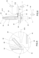
figure 4 depicts a partial view of a winding unit according to an embodiment useful for understanding the present invention; -
figure 5 depicts the enlarged detail V offigure 4 ; -
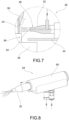
figure 6 depicts a partial view of a winding unit according to an embodiment of the present invention; -
figure 7 depicts the enlarged detail VII offigure 6 ; -
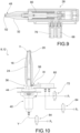
figure 8 depicts a perspective view of a tube locking pusher according to a possible embodiment of the present invention; -
figure 9 depicts a cross-section view of the tube locking pusher offigure 8 ; -
figure 10 depicts a partial view of a winding unit comprising the locking pusher offigures 8-9 ; -
figure 11 depicts the enlarged detail XI offigure 10 ; -
figures 12-15 depict cross-section views of successive operating steps of the winding unit offigure 10 ; -
figure 16 depicts the time trend of the pressures in the solenoid valves of the winding unit offigure 10 , during the operating steps illustrated infigures 12-15 ; -
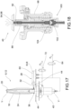
figure 17 depicts a partial view of a winding unit according to a further embodiment of the present invention; -
figure 18 depicts a cross-section view of a plate centring pusher in accordance with the present invention, in an extracted configuration; -
figure 19 depicts a cross-section view of the enlarged detail XIX offigure 18 ; -
figure 20 depicts a cross-section view of the plate centring pusher offigures 18-18 in an extracted configuration; -
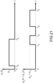
figure 21 depicts the time trend of the pressures of the tube locking and plate centring pushers of the winding unit according to the embodiment offigures 17-20 . - The elements or parts of elements common to the embodiments described below will be indicated using the same reference numerals.
- With reference to the aforesaid figures,
reference numeral 4 globally denotes a winding machine comprising a plurality ofwinding units 8. - At least one
winding unit 8 comprises a spool changing device 12, for changingspools 16 comprisingyarn 20 wound on atube 24 supported by aplate 26. Thetube 24 extends along a vertical axis Y-Y, preferably perpendicular to theplate 26. - It should be noted that the term thread or single thread or continuous thread refers to a single filament or continuous filament (for example in the case of silk, artificial or synthetic fibres) while the term yarn refers to a group of fibrils of varying lengths which are paralleled and joined together by twisting. Hereinafter, one or the other term will be used indifferently, it being understood that the applications of the present invention are generic and all-encompassing, i.e., not limited to one or the other type/material.
- The spool changing device 12 is provided with a
tube locking pusher 28, provided with alocking stem 32 configured to pass from a retracted configuration, in which it does not interfere with thetube 24 of thespool 16, to an extracted configuration in which it obtains a constraint, preferably but not exclusively along a radial direction R-R, at alower portion 36 of thetube 24 of thespool 16, facingsaid plate 26. - The radial direction R-R is preferably perpendicular and incident with respect to the vertical axis Y-Y of the
tube 24. - The
winding unit 8 further comprises aplate centring pusher 40 configured to influence, in an extracted configuration, theplate 26 abutting against aframe 44 of the spool changing device 12. - Advantageously, the spool changing device 12 is provided with at least one
nozzle 48 positioned and configured so as to direct, through at least onedelivery hole 52, a jet of compressed air near saidlower portion 36 of thetube 24 of thespool 16 influenced by thetube locking pusher 28, to prevent saidtube locking pusher 28 from clamping athread 56 of saidyarn 20 wound on thetube 24 and positioned near saidlower portion 36. - In the following, reference will be made in particular to
tube locking pushers 28 andplate centring pushers 40 of the pneumatically operated linear type (cylinders), meaning however that the invention is applicable to any other type of pushers, such as linear electric motors. Typically, said pushers slide axially insiderelative cylinders 60. - In accordance with a possible embodiment (
figures 4-5 ), not according to the claimed invention, saidnozzle 48 is integral with theframe 44 of the spool changing device 12. In such an embodiment, thenozzle 48 does not move with the passage of thetube locking pusher 28 from the retracted configuration to the extracted configuration. - In accordance with the present invention (
figures 6-7 ) saidnozzle 48 is integrally fixed to saidlocking stem 32. - The
nozzle 48 injects air at a delivery pressure p_2, for example by means of a secondpneumatic solenoid valve 64, through said at least onedelivery hole 52 obtained at the tip of the locking stem near the contact area (lower portion 36) during the stroke of thetube locking pusher 28 to move thethread 56 away and prevent the latter from being accidentally clamped by thelocking stem 32. - According to a particularly advantageous embodiment, the
tube locking pusher 28 is configured as a pneumatic cylinder provided with afirst chamber 68, placed under pressure p_1 by afirst solenoid valve 72, and asecond chamber 76, placed under pressure p_2 by thesecond solenoid valve 64. Bothchambers locking stem 32 of thetube locking pusher 28. - Preferably, the
second chamber 76 is hermetic and coaxial with respect to thefirst chamber 68. - For example, the
second chamber 76 houses anelastic return element 80 of the lockingstem 32 which elastically influences said lockingstem 32 in said extracted position. - The
tube locking pusher 28 is provided at the tip with acylindrical delivery hole 52 coaxial with the lockingstem 32 and fluidly connected to thesecond chamber 76. As will be better clarified below, the puff of air is integrated with the movement of thetube locking pusher 28 from both a constructive and a functional point of view, resulting in a greater compactness of the device and in a greater effectiveness of controlling the position of thethread 56, so that the latter is not accidentally clamped by thetube locking pusher 28. - For example, said at least one
delivery hole 52 is arranged coaxial with respect to a main extension axis of the lockingstem 32, arranged parallel to said radial direction R-R. - The
delivery hole 52 of thenozzle 48 has a diameter between 0.2 mm and 1.2 mm, preferably equal to 0.5 mm. - The stroke of the
tube locking pusher 28, equal to the distance between the retracted position and the extracted position, is between 5 mm and 15 mm, preferably 10 mm. - In accordance with an embodiment, the
first solenoid valve 72, which controls the locking/unlocking of thetube locking pusher 28, is of the normally closed 3/2 type. - In accordance with an embodiment, the
second solenoid valve 64, which controls the puff of air as well as the stroke of the lockingstem 32, is of the normally closed 2/2 type. - For example, the winding
unit 8 is provided with a spool unthreading jet fed by athird solenoid valve 84. - It should be noted that the supply pressures p_1 and p_2 can be distinct or equal to each other, and may or may not coincide with the line pressure of the plant. The same applies to the unthreading pressure p_3.
- In accordance with a particularly advantageous embodiment (
figures 18-20 ), saidplate centring pusher 40 comprises acentring stem 88 provided with a throughhole 92 configured so that, when it is extracted in the locking position of theplate 26, it allows a jet of unthreading air to flow therein, through said throughhole 92. - The jet of unthreading air exits through at least one circular sector-shaped
slot 94 obtained on asleeve 96 of theaxial centring cylinder 98 which houses and guides saidplate centring pusher 40. - For example, the
plate centring pusher 40 is configured so that when thecentring stem 88 retracts disengaging theplate 26, it blocks the unthreading flow by occluding the at least oneslot 94 with thecentring stem 88 and pressing against ahermetic closing element 100. - In plate-locking conditions, the at least one
slot 94 is kept open by thehermetic closing element 100, for example in the form of a rubber plug, coaxial to thecentring stem 88, which abuts against ashoulder 104 of theaxial centring cylinder 98, by virtue of the action of aspring 102, and thus creates a by-pass for the air. - With respect to the traditional cycle (
figure 21 ), when at the initial instant t_0 the twopushers second solenoid valve 64 is switched, only the puff of thetube locking pusher 28 is fed. At the instant t_2 thetube locking pusher 28 intercepts thetube 24. At the instant t_3 thefirst solenoid valve 72 is switched and thus also theplate centring pusher 40 centres theplate 26. Thereby, however, by virtue of the construction of theplate centring pusher 40, the unthreading jet is fed, being controlled by the same solenoid valve used for the puff of the pusher. - With respect to the previous case, then, the interval t_3-t_2, which determines the delay of extinguishing the puff of the
tube locking pusher 28, cannot be chosen arbitrarily, having to reconcile on the one hand the need to reach thetube 24 with certainty and on the other to prevent the undesired triggering of unthreading. Therefore, the duration of such an interval t_3-t_2 is assumed to be 20 ms. By virtue of this configuration, it will therefore be possible to perform the unthreading separately and independently during the interval t_5-t_4 with one less solenoid valve, certain of the fact that upon the unthreading the air will only exit from the stem of theplate centring pusher 40, the puff being plugged by the contact with thetube 24 itself. - The functioning of the winding unit in accordance with the present invention will now be described.
- In particular, during the passage in the extracted configuration of the locking
stem 32 of thetube locking pusher 28, a jet of compressed air is directed, through thedelivery hole 52 of said nozzle 48 (whether it is separated or integrated in the tube locking pusher 28), near saidlower portion 36 of thetube 24 of thespool 16, to prevent saidtube locking pusher 28 from clamping athread 56 of saidyarn 20 wound on thetube 24. - More in detail (
figure 12 ), at an initial instant t_0, once thespool 16 has reached theplate 26, pressure is put on thefirst chamber 68 at pressure p_1 and thetube clamping pusher 28 and the plate 26 (being controlled by the same solenoid valve) are retracted with relative compression of theelastic return element 80 acting on the lockingstem 32. - At an instant t_1 (
figure 13 ), the operation continues with the step of switching thesecond solenoid valve 64 which allows the air to flow into thesecond chamber 76 and then through thedelivery hole 52 at the tip of thetube locking pusher 28, with consequent deviation of thethread 56 free of yarn from thetube 24. - Since during the filling step the air flow rate of the puff is significantly lower than the inlet flow rate to the
second chamber 76, the latter is gradually pressurized, progressively overcoming the elastic load of theelastic return element 80 compressed by thefirst chamber 68 and gradually releasing thetube locking pusher 28 towards the tube 24 (figure 14 ). - At an instant t_2 (
figure 15 ) the position of thefirst solenoid valve 72 is switched and theelastic return element 80 discharges the residual elastic load stored thereby onto thetube 24, which thus ensures the correct retention of the tube 24: in other words, the radial locking of thetube 24 in unravelling is provided by the cylinder spring. - Furthermore, the
plate centring pusher 40 exits, pressing theplate 26 against theframe 44 of the spool changing device 12 to lock it in position. - The time interval t_2-t_1 is approximately 30 ms and coincides with the time necessary to achieve the nominal stroke of the
tube locking stem 28. - The switching off of the
second solenoid valve 64 is delayed to an instant t_3 to ensure that the lockingstem 32 of thetube locking pusher 28 actually reaches thetube 24 and that at the same time thethread 56 continues to be deflected precisely at upon the locking (figure 16 ). - This solution, in addition to ensuring the puff in the approaching stroke of the
tube locking pusher 28, also makes the movement of thetube locking pusher 28 slower, gradual and controllable, thus increasing the effectiveness of the puff diverting action. - The
third solenoid valve 84, responsible for controlling the unthreading and independent of the other twosolenoid valves - The interval t_3-t_2, which determines the delay of extinguishing the puff of the
tube locking pusher 28, is chosen so as to reconcile, on the one hand, the need to reach thetube 24 with certainty and, on the other, the need to prevent the undesired triggering of unthreading. - The duration of said interval t_3-t_2 is between 18 ms and 22 ms, and preferably is 20 ms.
- Starting from the embodiment described above, it is possible to obtain further advantages in terms of simplification of the pneumatic system at the service of the various functions, by exploiting the occlusion of the radial locking puff when the
tube locking pusher 28 is in contact with thetube 24 and by appropriately modifying the design of theplate centring pusher 40, as described above. It is thereby possible to eliminate thethird solenoid valve 84 dedicated to unthreading, feeding this last function with the same solenoid valve which controls the puff of thetube locking pusher 28 and configuring theplate centring pusher 40 so that, depending on the operating position of its stem, it can divert the air flow to perform the following two functions: - in the locking position of the
plate 26, theplate centring pusher 40 performs the unthreading of thethread 56; - in the
plate release position 26, the air from the valve is diverted to thetube locking pusher 28 to move thethread 56. - As may be appreciated from the description, the present invention makes it possible to overcome the drawbacks mentioned of the prior art and to obtain considerable operational advantages.
- First of all, the simplification of the unravelling cycle is achieved by reducing the number of operating cycles of the pushers and the consequent improvement of their operating performance in terms of useful life.
- Furthermore, the risk of undesired clamping of the lower thread of the spool is eliminated and the consequent reduction in the number of alarms sounded by the spool thread nozzle.
- Furthermore, the amount of threads introduced into the machine and the textile working environment is reduced, resulting in an overall improvement in the cleaning of the winding unit.
- Furthermore, the sensorization on board the winding unit is reduced, as systems for controlling the presence of yarn at the end of the tube (e.g., photocells), with the consequent elimination of the risk of dirtying them.
- By virtue of the substantial simultaneity of the puff and the advancement of the radial locking pusher, two steps are performed in one and therefore a better control of the thread dynamics.
- Furthermore, it is possible to obtain a greater overall compactness of the device due to the integration of the puff inside the radial pusher.
- The overall reduction in the number of solenoid valves necessary for operation leads to the simplification of the machine's pneumatic architecture.
- Furthermore, an increase in the operating reliability and productivity of the winding unit, and therefore of the entire machine, is obtained.
- Therefore, the fundamental concept underlying the invention relates to the juxtaposition of a pneumatic puff substantially simultaneous with the advancement stroke of the tube locking pusher. The adverb "substantially" is intended to protect also those embodiments in which the puff is not exactly simultaneous with the stroke of the tube locking pusher, but starts and ends respectively immediately before and/or immediately after the start and end of the stroke of the tube locking pusher. The impulsive action of the puff pushes the thread away during the stroke of the pusher, eliminating the undesired risk of clamping and allowing in particular the control of the thread only when really necessary, i.e., from the beginning of the stroke of the tube locking pusher until contact with the tube itself. In fact, if the puff were not operated simultaneously with the advancement of the tube locking pusher, there would be some considerable disadvantages (which are solved by the present invention), such as unnecessary and unsolicited air consumption, as well as a less reliable control of the thread due to the elastic return thereof in the interference position with the tube locking pusher for premature interruption of the puff.
- A person skilled in the art may make numerous modifications and variations to the solutions described above so as to satisfy contingent and specific requirements.
- The scope of protection of the present invention is defined by the following claims.
Claims (14)
- Winding unit (8) comprising a spool changing device (12), for changing spools (16) comprising yarn (20) wound on a tube (24) supported by a plate (26), the spool changing device (12) being provided with:- a tube locking pusher (28), provided with a locking stem (32) configured to pass from a retracted configuration, in which it does not interfere with the tube (24) of the spool (16), to an extracted configuration in which it obtains a constraint at a lower portion (36) of the tube (24) of the spool (16), facing said plate (26),- a plate centring pusher (40) configured to influence, in an extracted configuration, the plate (26) abutting against a frame (44) of the spool changing device (12),- characterized in that the spool changing device (12) is provided with at least one nozzle (48) positioned and configured so as to direct, through at least one delivery hole (52), a jet of compressed air near said lower portion (36) of the tube (24) of the spool (16) influenced by the tube locking pusher (28), to prevent said tube locking pusher (28) from clamping a thread (56) of said yarn (20) wound on the tube (24),wherein said nozzle (48) is integrally fixed to said locking stem (32).
- Winding unit (8) according to claim 1, wherein the nozzle (48) injects air through said at least one delivery hole (52) obtained at the tip of the locking stem (32).
- Winding unit (8) according to claim 2, wherein said at least one delivery hole (52) is arranged coaxial with respect to a main extension axis of the locking stem (32).
- Winding unit (8) according to any one of claims 1 to 3, wherein the tube locking pusher (28) is configured as a pneumatic cylinder (60) provided with a first chamber (68), placed under pressure p_1 by a first solenoid valve (72), and a second chamber (76), placed at a pressure p_2 by a second solenoid valve (64), both chambers (68,76) being in fluid communication with said locking stem (32) of the tube locking pusher (28).
- Winding unit (8) according to claim 4, wherein the second chamber (76) is hermetic and coaxial with respect to the first chamber (68).
- Winding unit (8) according to claim 4 or 5, wherein the second chamber (76) houses an elastic return element (80) of the locking stem (32) which elastically influences said locking stem (32) in said extracted position.
- Winding unit (8) according to claim 4, 5, or 6, wherein the tube locking pusher (28) is provided at the tip with a cylindrical delivery hole (52) coaxial with the locking stem (32) and fluidically connected to the second chamber (76).
- Winding unit (8) according to any one of claims 4 to 7, wherein the winding unit (8) is provided with a spool unthreading jet fed by a third solenoid valve (84).
- Winding unit (8) according to any one of claims 4 to 8, wherein said plate centring pusher (40) comprises a centring stem (88) provided with an inner through hole (92) and is configured so that, when it is extracted in the plate locking position it allows a jet of unthreading air to flow therein, through said inner through hole (92), wherein said jet of unthreading air exits through at least one circular sector-shaped slot (94) obtained on a sleeve (96) of an axial centring cylinder (98) which houses and guides said plate centring pusher (40).
- Winding unit (8) according to claim 9, wherein said plate centring pusher (40) is configured so that when the centring stem (88) is retracted, disengaging the plate (26), it blocks the unthreading flow by occluding the at least one slot (94) with the centring stem (88) and pressing against a hermetic closing element (100), wherein the at least one slot (94) is kept open by said hermetic closing element (100), for example in the form of a rubber dowel, coaxial to the centring stem (88), which abuts against a shoulder (104) of the axial centring cylinder (98).
- Control method of a winding machine (4) comprising the steps of:- providing a winding unit (8) according to any one of claims 1 to 10;- during the passage in the extracted configuration of the locking stem (32) of the tube locking pusher (28), directing a jet of compressed air, through the delivery hole (52) of said nozzle (48), near said lower portion (36) of the tube (24) of the spool (16), to prevent said tube locking pusher (28) from clamping a thread (56) of said yarn (20) wound on the tube (24).
- Control method according to claim 11, comprising the steps of:- providing a winding unit (8) according to any one of claims 6 to 7,- at an initial instant t_0, once the spool (16) has reached the plate (26), putting pressure on the first chamber (68) at pressure p_1 and retracting the tube locking pusher (28) with relative compression of the elastic return element (80) acting on the locking stem (32),- at a time t_1, switching the second solenoid valve (64) which allows air to flow into the second chamber (76) and then through the delivery hole (52) at the tip of the tube locking pusher (28), with consequent deviation of the thread (56) free of yarn (20) from the tube (24),- wherein, since during the filling step the air flow rate of the puff is significantly lower than the inlet flow rate to the second chamber (76), the latter is gradually pressurized, progressively overcoming the elastic load of the elastic return element (80) compressed by the first chamber (68) and gradually releasing the tube locking pusher (28) towards the tube (24).
- Control method according to claim 12, wherein- at an instant t_2 the position of the first solenoid valve (72) is switched and the elastic return element (80) discharges the residual elastic load stored thereby onto the tube (24), which thus ensures the retention of the tube (24), wherein the plate centring pusher (40) exits, pressing the plate (26) against the frame (44) of the spool changing device (12) to lock it in place.
- Control method according to claim 12 or 13, wherein the switching off of the second solenoid valve (64) is delayed to an instant t_3 to ensure that the locking stem (32) of the tube locking pusher (28) actually reaches the tube (24) and that at the same time the thread (56) continues to be deflected precisely upon the locking, wherein a third solenoid valve (84), responsible for controlling the unthreading and independent of the other two solenoid valves (64,72), is switched after the instant t_3 and feeds the air jet inside the tube (24) at a pressure p_3 for a predefined interval t_5-t_4.
Applications Claiming Priority (1)
| Application Number | Priority Date | Filing Date | Title |
|---|---|---|---|
| IT102021000031307A IT202100031307A1 (en) | 2021-12-14 | 2021-12-14 | WINDING UNIT WITH IMPROVED TUBE LOCKING PUSHER AND PLATE CENTERING PUSHER AND RELATED CONTROL METHOD |
Publications (2)
| Publication Number | Publication Date |
|---|---|
| EP4197950A1 EP4197950A1 (en) | 2023-06-21 |
| EP4197950B1 true EP4197950B1 (en) | 2025-02-26 |
Family
ID=80448560
Family Applications (1)
| Application Number | Title | Priority Date | Filing Date |
|---|---|---|---|
| EP22202362.4A Active EP4197950B1 (en) | 2021-12-14 | 2022-10-19 | Winding unit with improved tube locking pusher and plate centring pusher and the relative control method |
Country Status (3)
| Country | Link |
|---|---|
| EP (1) | EP4197950B1 (en) |
| CN (2) | CN116262578A (en) |
| IT (1) | IT202100031307A1 (en) |
Family Cites Families (4)
| Publication number | Priority date | Publication date | Assignee | Title |
|---|---|---|---|---|
| JPS6023260A (en) * | 1983-07-19 | 1985-02-05 | Murata Mach Ltd | Yarn end delivering device |
| US5374000A (en) * | 1992-01-30 | 1994-12-20 | Murata Kikai Kabushiki Kaisha | Cop changing mechanism for a winding unit |
| US5590845A (en) * | 1993-09-24 | 1997-01-07 | Murata Kikai Kabushiki Kaisha | Yarn end finding apparatus and method |
| ITMI20070134A1 (en) * | 2007-01-29 | 2008-07-30 | Savio Macchine Tessili Spa | AUTOMATIC ROCKING STATION |
-
2021
- 2021-12-14 IT IT102021000031307A patent/IT202100031307A1/en unknown
-
2022
- 2022-10-19 EP EP22202362.4A patent/EP4197950B1/en active Active
- 2022-11-30 CN CN202211520012.8A patent/CN116262578A/en active Pending
- 2022-11-30 CN CN202223216794.4U patent/CN218968482U/en active Active
Also Published As
| Publication number | Publication date |
|---|---|
| IT202100031307A1 (en) | 2023-06-14 |
| CN116262578A (en) | 2023-06-16 |
| EP4197950A1 (en) | 2023-06-21 |
| CN218968482U (en) | 2023-05-05 |
Similar Documents
| Publication | Publication Date | Title |
|---|---|---|
| JPH026639A (en) | Method and device for splicing yarn in an open-end spinning device | |
| JP2007513265A (en) | Method and apparatus for production of coated elastic yarn and automatic replacement of supply spool | |
| CN101910486B (en) | Method and knitting machine for producing knitwear from untwisted fiber material | |
| CZ20022313A3 (en) | Service unit for restarting the spinning of work stations in an open-end spinning machine | |
| EP4197950A1 (en) | Winding unit with improved tube locking pusher and plate centring pusher and the relative control method | |
| US3544018A (en) | Bobbin handling | |
| CN101910483A (en) | Method and circular knitting machine for producing knitwear from untwisted fiber material | |
| EP0943714B1 (en) | Process and apparatus for reducing the lead-in thread length in circular knitting machines | |
| JPH03223073A (en) | Device for splicing threads at take-up part of winder and automatically replacing cup | |
| EP2230342A1 (en) | Storage device and method for storing weft threads in a loom | |
| EP1314673B1 (en) | Device and process for removing the defective end portions from yarn on a package fedto an automatic winder | |
| IT201900009687A1 (en) | DEVICE AND METHOD FOR THE CONTROL OF A BALLOON DURING THE DRAWING OF A YARN FROM A SPOOL | |
| US5072760A (en) | Device for drawing a yarn into a weft accumulator | |
| US6199598B1 (en) | Measuring feeding device with brake shoe clamp | |
| ITMI20070134A1 (en) | AUTOMATIC ROCKING STATION | |
| US5441087A (en) | Yarn storage and feed device utilizing correctional air jet nozzles | |
| US6591600B2 (en) | Rotor spinning machine | |
| EP1712509B1 (en) | Device and process for handling and controlling the yarn of a crosswinding head of a crosswinding machine during the starting operations of a new lot | |
| CS9004713A2 (en) | Weft feeder for jet looms | |
| CZ58394A3 (en) | Weft feeder for gripper shuttle and needle looms | |
| CZ87698A3 (en) | A device for blocking weft yarn during its shearing for assignment to a weft measuring feeder | |
| US5018557A (en) | Weft-switching system with telescoping nozzles | |
| US5170822A (en) | Yarn storage and feed device with axially adjustable yarn stopping element | |
| CN113355773A (en) | Method for operating a spinning or winding machine and spinning or winding machine | |
| JP2019525017A (en) | Method for processing strip-shaped fiber assembly and roving machine |
Legal Events
| Date | Code | Title | Description |
|---|---|---|---|
| PUAI | Public reference made under article 153(3) epc to a published international application that has entered the european phase |
Free format text: ORIGINAL CODE: 0009012 |
|
| STAA | Information on the status of an ep patent application or granted ep patent |
Free format text: STATUS: THE APPLICATION HAS BEEN PUBLISHED |
|
| AK | Designated contracting states |
Kind code of ref document: A1 Designated state(s): AL AT BE BG CH CY CZ DE DK EE ES FI FR GB GR HR HU IE IS IT LI LT LU LV MC ME MK MT NL NO PL PT RO RS SE SI SK SM TR |
|
| P01 | Opt-out of the competence of the unified patent court (upc) registered |
Effective date: 20230628 |
|
| STAA | Information on the status of an ep patent application or granted ep patent |
Free format text: STATUS: REQUEST FOR EXAMINATION WAS MADE |
|
| 17P | Request for examination filed |
Effective date: 20231219 |
|
| RBV | Designated contracting states (corrected) |
Designated state(s): AL AT BE BG CH CY CZ DE DK EE ES FI FR GB GR HR HU IE IS IT LI LT LU LV MC ME MK MT NL NO PL PT RO RS SE SI SK SM TR |
|
| GRAP | Despatch of communication of intention to grant a patent |
Free format text: ORIGINAL CODE: EPIDOSNIGR1 |
|
| STAA | Information on the status of an ep patent application or granted ep patent |
Free format text: STATUS: GRANT OF PATENT IS INTENDED |
|
| GRAS | Grant fee paid |
Free format text: ORIGINAL CODE: EPIDOSNIGR3 |
|
| INTG | Intention to grant announced |
Effective date: 20241127 |
|
| GRAA | (expected) grant |
Free format text: ORIGINAL CODE: 0009210 |
|
| STAA | Information on the status of an ep patent application or granted ep patent |
Free format text: STATUS: THE PATENT HAS BEEN GRANTED |
|
| AK | Designated contracting states |
Kind code of ref document: B1 Designated state(s): AL AT BE BG CH CY CZ DE DK EE ES FI FR GB GR HR HU IE IS IT LI LT LU LV MC ME MK MT NL NO PL PT RO RS SE SI SK SM TR |
|
| REG | Reference to a national code |
Ref country code: GB Ref legal event code: FG4D |
|
| REG | Reference to a national code |
Ref country code: CH Ref legal event code: EP |
|
| REG | Reference to a national code |
Ref country code: DE Ref legal event code: R096 Ref document number: 602022011056 Country of ref document: DE |
|
| REG | Reference to a national code |
Ref country code: IE Ref legal event code: FG4D |
|
| REG | Reference to a national code |
Ref country code: NL Ref legal event code: MP Effective date: 20250226 |
|
| PG25 | Lapsed in a contracting state [announced via postgrant information from national office to epo] |
Ref country code: RS Free format text: LAPSE BECAUSE OF FAILURE TO SUBMIT A TRANSLATION OF THE DESCRIPTION OR TO PAY THE FEE WITHIN THE PRESCRIBED TIME-LIMIT Effective date: 20250526 |
|
| PG25 | Lapsed in a contracting state [announced via postgrant information from national office to epo] |
Ref country code: FI Free format text: LAPSE BECAUSE OF FAILURE TO SUBMIT A TRANSLATION OF THE DESCRIPTION OR TO PAY THE FEE WITHIN THE PRESCRIBED TIME-LIMIT Effective date: 20250226 |
|
| PG25 | Lapsed in a contracting state [announced via postgrant information from national office to epo] |
Ref country code: PL Free format text: LAPSE BECAUSE OF FAILURE TO SUBMIT A TRANSLATION OF THE DESCRIPTION OR TO PAY THE FEE WITHIN THE PRESCRIBED TIME-LIMIT Effective date: 20250226 |
|
| PG25 | Lapsed in a contracting state [announced via postgrant information from national office to epo] |
Ref country code: ES Free format text: LAPSE BECAUSE OF FAILURE TO SUBMIT A TRANSLATION OF THE DESCRIPTION OR TO PAY THE FEE WITHIN THE PRESCRIBED TIME-LIMIT Effective date: 20250226 |
|
| REG | Reference to a national code |
Ref country code: LT Ref legal event code: MG9D |
|
| PG25 | Lapsed in a contracting state [announced via postgrant information from national office to epo] |
Ref country code: NO Free format text: LAPSE BECAUSE OF FAILURE TO SUBMIT A TRANSLATION OF THE DESCRIPTION OR TO PAY THE FEE WITHIN THE PRESCRIBED TIME-LIMIT Effective date: 20250526 Ref country code: IS Free format text: LAPSE BECAUSE OF FAILURE TO SUBMIT A TRANSLATION OF THE DESCRIPTION OR TO PAY THE FEE WITHIN THE PRESCRIBED TIME-LIMIT Effective date: 20250626 |
|
| PG25 | Lapsed in a contracting state [announced via postgrant information from national office to epo] |
Ref country code: NL Free format text: LAPSE BECAUSE OF FAILURE TO SUBMIT A TRANSLATION OF THE DESCRIPTION OR TO PAY THE FEE WITHIN THE PRESCRIBED TIME-LIMIT Effective date: 20250226 |
|
| PG25 | Lapsed in a contracting state [announced via postgrant information from national office to epo] |
Ref country code: HR Free format text: LAPSE BECAUSE OF FAILURE TO SUBMIT A TRANSLATION OF THE DESCRIPTION OR TO PAY THE FEE WITHIN THE PRESCRIBED TIME-LIMIT Effective date: 20250226 |
|
| PG25 | Lapsed in a contracting state [announced via postgrant information from national office to epo] |
Ref country code: PT Free format text: LAPSE BECAUSE OF FAILURE TO SUBMIT A TRANSLATION OF THE DESCRIPTION OR TO PAY THE FEE WITHIN THE PRESCRIBED TIME-LIMIT Effective date: 20250626 Ref country code: LV Free format text: LAPSE BECAUSE OF FAILURE TO SUBMIT A TRANSLATION OF THE DESCRIPTION OR TO PAY THE FEE WITHIN THE PRESCRIBED TIME-LIMIT Effective date: 20250226 |
|
| PG25 | Lapsed in a contracting state [announced via postgrant information from national office to epo] |
Ref country code: GR Free format text: LAPSE BECAUSE OF FAILURE TO SUBMIT A TRANSLATION OF THE DESCRIPTION OR TO PAY THE FEE WITHIN THE PRESCRIBED TIME-LIMIT Effective date: 20250527 Ref country code: BG Free format text: LAPSE BECAUSE OF FAILURE TO SUBMIT A TRANSLATION OF THE DESCRIPTION OR TO PAY THE FEE WITHIN THE PRESCRIBED TIME-LIMIT Effective date: 20250226 |
|
| REG | Reference to a national code |
Ref country code: AT Ref legal event code: MK05 Ref document number: 1770480 Country of ref document: AT Kind code of ref document: T Effective date: 20250226 |
|
| PG25 | Lapsed in a contracting state [announced via postgrant information from national office to epo] |
Ref country code: SE Free format text: LAPSE BECAUSE OF FAILURE TO SUBMIT A TRANSLATION OF THE DESCRIPTION OR TO PAY THE FEE WITHIN THE PRESCRIBED TIME-LIMIT Effective date: 20250226 |
|
| PG25 | Lapsed in a contracting state [announced via postgrant information from national office to epo] |
Ref country code: SM Free format text: LAPSE BECAUSE OF FAILURE TO SUBMIT A TRANSLATION OF THE DESCRIPTION OR TO PAY THE FEE WITHIN THE PRESCRIBED TIME-LIMIT Effective date: 20250226 |
|
| PG25 | Lapsed in a contracting state [announced via postgrant information from national office to epo] |
Ref country code: DK Free format text: LAPSE BECAUSE OF FAILURE TO SUBMIT A TRANSLATION OF THE DESCRIPTION OR TO PAY THE FEE WITHIN THE PRESCRIBED TIME-LIMIT Effective date: 20250226 |
|
| PG25 | Lapsed in a contracting state [announced via postgrant information from national office to epo] |
Ref country code: AT Free format text: LAPSE BECAUSE OF FAILURE TO SUBMIT A TRANSLATION OF THE DESCRIPTION OR TO PAY THE FEE WITHIN THE PRESCRIBED TIME-LIMIT Effective date: 20250226 |
|
| PG25 | Lapsed in a contracting state [announced via postgrant information from national office to epo] |
Ref country code: EE Free format text: LAPSE BECAUSE OF FAILURE TO SUBMIT A TRANSLATION OF THE DESCRIPTION OR TO PAY THE FEE WITHIN THE PRESCRIBED TIME-LIMIT Effective date: 20250226 Ref country code: CZ Free format text: LAPSE BECAUSE OF FAILURE TO SUBMIT A TRANSLATION OF THE DESCRIPTION OR TO PAY THE FEE WITHIN THE PRESCRIBED TIME-LIMIT Effective date: 20250226 |
|
| PG25 | Lapsed in a contracting state [announced via postgrant information from national office to epo] |
Ref country code: RO Free format text: LAPSE BECAUSE OF FAILURE TO SUBMIT A TRANSLATION OF THE DESCRIPTION OR TO PAY THE FEE WITHIN THE PRESCRIBED TIME-LIMIT Effective date: 20250226 |
|
| PG25 | Lapsed in a contracting state [announced via postgrant information from national office to epo] |
Ref country code: SK Free format text: LAPSE BECAUSE OF FAILURE TO SUBMIT A TRANSLATION OF THE DESCRIPTION OR TO PAY THE FEE WITHIN THE PRESCRIBED TIME-LIMIT Effective date: 20250226 |
|
| REG | Reference to a national code |
Ref country code: DE Ref legal event code: R097 Ref document number: 602022011056 Country of ref document: DE |
|
| PLBE | No opposition filed within time limit |
Free format text: ORIGINAL CODE: 0009261 |
|
| STAA | Information on the status of an ep patent application or granted ep patent |
Free format text: STATUS: NO OPPOSITION FILED WITHIN TIME LIMIT |
|
| PGFP | Annual fee paid to national office [announced via postgrant information from national office to epo] |
Ref country code: DE Payment date: 20251027 Year of fee payment: 4 |
|
| PGFP | Annual fee paid to national office [announced via postgrant information from national office to epo] |
Ref country code: IT Payment date: 20251031 Year of fee payment: 4 |
|
| PGFP | Annual fee paid to national office [announced via postgrant information from national office to epo] |
Ref country code: TR Payment date: 20251006 Year of fee payment: 4 |
|
| 26N | No opposition filed |
Effective date: 20251127 |