EP4197860A1 - Storage compartment for a passenger cabin of a vehicle - Google Patents
Storage compartment for a passenger cabin of a vehicle Download PDFInfo
- Publication number
- EP4197860A1 EP4197860A1 EP22213967.7A EP22213967A EP4197860A1 EP 4197860 A1 EP4197860 A1 EP 4197860A1 EP 22213967 A EP22213967 A EP 22213967A EP 4197860 A1 EP4197860 A1 EP 4197860A1
- Authority
- EP
- European Patent Office
- Prior art keywords
- panel
- storage compartment
- vehicle
- door
- access
- Prior art date
- Legal status (The legal status is an assumption and is not a legal conclusion. Google has not performed a legal analysis and makes no representation as to the accuracy of the status listed.)
- Pending
Links
- 230000002787 reinforcement Effects 0.000 claims description 28
- 241001417494 Sciaenidae Species 0.000 claims description 18
- 239000010410 layer Substances 0.000 description 18
- 239000000758 substrate Substances 0.000 description 10
- 239000000463 material Substances 0.000 description 7
- 239000004033 plastic Substances 0.000 description 5
- 238000012986 modification Methods 0.000 description 3
- 230000004048 modification Effects 0.000 description 3
- 239000002023 wood Substances 0.000 description 3
- 239000004609 Impact Modifier Substances 0.000 description 2
- 241000446313 Lamella Species 0.000 description 2
- 239000004677 Nylon Substances 0.000 description 2
- 229920007019 PC/ABS Polymers 0.000 description 2
- 239000000654 additive Substances 0.000 description 2
- 238000010276 construction Methods 0.000 description 2
- 230000009977 dual effect Effects 0.000 description 2
- 239000000945 filler Substances 0.000 description 2
- 239000010985 leather Substances 0.000 description 2
- 229920001778 nylon Polymers 0.000 description 2
- 229920000728 polyester Polymers 0.000 description 2
- 239000012790 adhesive layer Substances 0.000 description 1
- 229910052782 aluminium Inorganic materials 0.000 description 1
- XAGFODPZIPBFFR-UHFFFAOYSA-N aluminium Chemical compound [Al] XAGFODPZIPBFFR-UHFFFAOYSA-N 0.000 description 1
- -1 etc.) Substances 0.000 description 1
- 239000003365 glass fiber Substances 0.000 description 1
- 229910052500 inorganic mineral Inorganic materials 0.000 description 1
- 239000007769 metal material Substances 0.000 description 1
- 239000011707 mineral Substances 0.000 description 1
- 239000000203 mixture Substances 0.000 description 1
- 238000010137 moulding (plastic) Methods 0.000 description 1
- 239000005445 natural material Substances 0.000 description 1
- 230000000284 resting effect Effects 0.000 description 1
- 239000002356 single layer Substances 0.000 description 1
- 239000007787 solid Substances 0.000 description 1
- 239000012815 thermoplastic material Substances 0.000 description 1
- XLYOFNOQVPJJNP-UHFFFAOYSA-N water Substances O XLYOFNOQVPJJNP-UHFFFAOYSA-N 0.000 description 1
Images


Classifications
-
- B—PERFORMING OPERATIONS; TRANSPORTING
- B60—VEHICLES IN GENERAL
- B60R—VEHICLES, VEHICLE FITTINGS, OR VEHICLE PARTS, NOT OTHERWISE PROVIDED FOR
- B60R7/00—Stowing or holding appliances inside vehicle primarily intended for personal property smaller than suit-cases, e.g. travelling articles, or maps
- B60R7/04—Stowing or holding appliances inside vehicle primarily intended for personal property smaller than suit-cases, e.g. travelling articles, or maps in driver or passenger space, e.g. using racks
Definitions
- the present disclosure is related generally to vehicle interiors and, more particularly, to storage compartments for passenger cabins of vehicles.
- Storage compartments such as those having tambour doors, have been used in various vehicle interior designs. However, they typically do not provide a sufficiently sized working space (e.g., a generally flat area for a laptop or the like), and they are often only accessible via one side of the storage compartment.
- a sufficiently sized working space e.g., a generally flat area for a laptop or the like
- US Patent Application Publication 2018/0222394 to Huebner et al. shows a dual tambour door design that has a working space on the top of the center console.
- access to the storage area is only permitted on one side. This can limit the type and amount of goods stored in the storage compartment, and may also hinder access to the storage compartment.
- An illustrative storage compartment comprises a plurality of walls forming an interior storage area, the plurality of walls including an exterior comprising at least a first panel and a second panel.
- the first panel has an access end and the second panel has an access end.
- the access end of the first panel and the access end of the second panel are configured to create a working surface on the exterior when in a closed position. In an open position, the first panel or the second panel is configured to allow access to the interior storage area from two or more different sides of the exterior.
- the first panel is a first tambour door and the second panel is a second tambour door.
- the two or more different sides join at a rounded radius.
- the two or more different sides includes a first side and a second side, with the first side configured to face a roof of the vehicle, and the second side configured to face a door of the vehicle.
- the two or more different sides includes a third side, with the third side configured to face another door of the vehicle.
- the first panel is configured to allow access to the interior storage area from the first side and the second side
- the second panel is configured to allow access to the interior storage area from the first side and the third side.
- the first panel and the second panel are configured to be placed between a center console and an instrument panel of the vehicle, whereby one of the plurality of walls is formed by, or located at, the center console and another of the plurality of walls is formed by, or located at, instrument panel.
- first reinforcement strap and a second reinforcement strap there is a first reinforcement strap and a second reinforcement strap, and the first reinforcement strap and the second reinforcement strap delimit a first side of the two or more different sides.
- the first reinforcement strap and the second reinforcement strap extend between a center console and an instrument panel of the vehicle.
- the first panel and the second panel are configured to slide under the first reinforcement strap and the second reinforcement strap, respectively, such that the first reinforcement strap and the second reinforcement strap are visible in the passenger cabin when in the closed position.
- the first panel and the second panel each have a recessed handle located toward the access end.
- the first panel has a recessed end opposite the access end and the second panel has a recessed end opposite the access end.
- the recessed end of the first panel is configured to overlap the recessed end of the second panel when in the open position.
- the recessed end of the first panel and the recessed end of the second panel are configured to overlap in a door space beneath an interior storage bin when in the open position.
- the interior storage bin has a sidewall that partially extends up two of the two or more different sides that each face a different door of the vehicle.
- a storage compartment that provides increased usability when in a closed position, and increased storage capacity and accessibility, particularly when in an open position.
- the storage compartment combines bomb bay style doors with jalousie or tambour style doors to more efficiently use space within a passenger cabin of a vehicle.
- each of the doors allows access to an interior storage area via two different sides of the storage compartment. This can provide for more convenient use of the storage compartment, while maintaining a streamlined and integrated vehicle interior appearance.
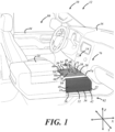
- FIG. 1 is a partial perspective view of a passenger cabin 10 for a vehicle 12 having a storage compartment 14.
- the storage compartment 14 is advantageously located between the instrument panel 16 and the center console 18. This particular location is advantageous because it is oftentimes generally unused, and it provides a working surface 20 for either the driver or a passenger in the front. More particularly, the storage compartment 14 is integrally built between the instrument panel 16 and the center console 18 such that both the instrument panel and the center console form opposite walls or sides 22, 24 of the storage compartment. However, it is possible for the storage compartment 14 to be located in other locations in the vehicle, such as between passenger seats in another row of seating, to cite one potential example. Alternatively, it is also possible to have a stand-alone storage compartment 14 that is then installed between a pre-existing instrument panel 16 and center console 18.
- the storage compartment 14 includes an exterior 26 and an interior storage area 28.
- a majority of the exterior 26 is generally defined by a first panel 30 and a second panel 32.
- the first panel 30 is a first tambour door 34 and the second panel 32 is a second tambour door 36.
- Tambour doors are particularly useful in implementations in which there is limited space, and they have an articulated construction that permits the doors to bend as they move along a curved path. This arrangement can be particularly advantageous here, where the storage compartment 14 is configured to allow access to the interior storage area 28 from a first side 38, a second side 40, and a third side 42.
- the doors 34, 36 form the sides or walls 38, 40, 42 when the storage compartment 14 is closed.
- the panels 30, 32 can take other operationally feasible configurations.
- the first or top side 38 of the storage compartment 14 faces the roof of the vehicle 12
- the second side 40 faces the driver's door 44
- the third side 42 faces the passenger's door (not shown).
- the first side 38 is formed by the first and second tambour doors 34, 36 when in a closed position, and generally forms a plane that is perpendicular to the Z-axis of the vehicle 12.
- the second side 40 and third side 42 oppose each other, and each generally form a plane that is perpendicular to the Y-axis of the vehicle 12. This arrangement allows easy access to the interior storage area 28 from the top (i.e., the first side 38) for either a driver of the vehicle 12 or a passenger in the front seat.
- the driver and passenger can also access the interior storage area 28 via each different second and third side 40, 42, respectively. Accordingly, the operability is enhanced as compared with typical in-vehicle storage compartments, where access to the interior storage area can only be accomplished through one side.
- the rectangular profile 46 includes rounded radii 48, 50, 52, 54 at each corner, which can help with operational efficiency when using tambour doors 34, 36.
- the rounded radius 48 is located between the first side 38 and the second side 40
- the rounded radius 50 is located between the is located between the first side 38 and the third side 42.
- the rounded radius 52 is located between the second side 40 and a fourth or bottom side 56
- the rounded radius 54 is located between the third side 42 and the fourth side 56.
- each of the sides 38, 40, 42, 56 are generally planar and angled with respect to adjoining sides, with the rounded radii located between each respective side.
- Other embodiments may have one or more sides that have a more curved profile, or the angles between the sides may be different than what is particularly illustrated.
- the rectangular profile 46 is also a strategically efficient use of space between the instrument panel 16 and the center console 18.
- the instrument panel 16 and the center console 18 provide structure to the storage compartment 14, providing for a more integrated look and feel.
- the storage compartment 14 may have other shapes, side numbers, side configurations, etc. depending on the desired implementation.
- the storage compartment 14 could be built into another area of the vehicle 12.
- the storage compartment 14 could be located on the back of the center console 18, in an armrest in the rear of the vehicle 12, or in another operable location.
- each first and second door 34, 36 has an access end 58, 60, respectively. Opposite the access ends 58, 60, each first and second door 34, 36 has a recessed end 62, 64, respectively.
- the access end 58 of the first door 34 meets the access end 60 of the second door 36 to form an opening 66.
- the opening 66 advantageously biases the first side 38, which can provide easier access for either a driver or a passenger.
- the opening 66 may include a seal, some type of closure mechanism or lock (e.g., magnets to help maintain the joining of the access ends 58, 60), or any other feature to help enhance protection of the interior storage area 28.
- the illustrated embodiment includes, for example, recessed handles 68, 70.
- Other handle arrangements (or no handles at all) may be included, but recessed handles 68, 70 provide for better articulation in the example embodiment, which includes reinforcement straps 72, 74 arranged outside of the interior storage area 28. Accordingly, during translation of each door 34, 36 from the closed position 76 ( FIG. 4 ) to the open position 78 ( FIG. 5 ), the recessed handle 68, 70 can easily pass beneath each reinforcement strap 72, 74.
- the recessed handles 68, 70 may provide for manual articulation of each door 34, 36, or in some embodiments, door movement may be motorized or otherwise assisted.
- the working surface 20 is large enough to comfortably hold a user's laptop (e.g., 20 inch x 20 inch). Accordingly, in at least some embodiments, the working surface 20 provides another raised, table-top-like surface for use from either the driver's side seating area 80 or the passenger's side seating area 82.
- the working surface 20 is available when the storage compartment 14 is in the closed position 76. However, when the storage compartment 14 is in the open position 78 (see e.g., FIG.
- the working surface 20 on the first or top side 38 is gone, in order to provide access to an interior storage bin 84 in the interior storage area 28.
- the working surface 20 may not be as big as what is illustrated in the figures, and it may be a smaller surface located elsewhere in the cabin 10.
- Each door 34, 36 includes a recessed end 62, 64 opposite the respective access end 58, 60.
- the recessed ends 62, 64 are recessed with respect to the exterior 26 of the storage compartment 14 (i.e., not visible within the passenger cabin 10) when in both the closed position 76 and the open position 78.
- Opposing articulating edges may connect the opposing access ends 58, 60 and recessed ends 62, 64 to form an outer perimeter of each door 34, 36.
- the articulating edges may include or interact with a roller system or some other mechanism to facilitate articulation of each door 34, 36 from the closed position 76 to the open position 78.
- the doors 34, 36 pass through each rounded radius 48, 50, 52, 54 into a door space 86 located between a lower panel 88 and the interior storage bin 84.
- the recessed end 62 of the first door 34 overlaps the recessed end 64 of the second door 36 creating an overlap region 90 where the first door, the second door, and the lower panel 88 are stacked beneath the interior storage bin 84.
- about two-thirds of the area of each door 34, 36 overlap in the overlap region 90, which accordingly translates to a larger opening 66 when in the open position 78.
- each door 34, 36 overlap in the overlap region 90.
- This arrangement conveniently locates the doors or panels 30, 32 beneath the storage bin 84 and provides for access into the interior storage area 28 through each of the three sides 38, 40, 42 of the storage compartment 14.
- the storage bin 84 may have a sidewall 92 that extends around the circumference of the storage bin to help retain items in the bin. This sidewall 92 partially extends up the sides 40, 42 of the storage compartment 14. The height of the sidewall 92 of the interior storage bin 84 can be controlled to help promote access through each of the sides 40, 42.
- the sidewall 92 and doors 34, 36 block about a third of the area of each side 40, 42 when in the open position 78.
- each side 40, 42 This allows for about two-thirds of each side 40, 42 to be open when in the open position 78. In other embodiments, this area might be about half or more, in order to allow for dual side access, in addition to access through the top. Accordingly, the interior storage bin sidewall 92 only partially blocks the sides 40, 42 to enhance accessibility of the interior storage area 28.
- each door 34, 36 in this embodiment includes a substrate 94 and a decorative layer 96 disposed over and coupled with the substrate.
- the decorative layer 96 is coupled with the underlying substrate 94 via a bonding layer 98, such as an adhesive layer or a cushioning layer having its opposite sides bonded with the back side of the decorative layer 96 and the outer side of the substrate 94.
- the substrate 94 has an articulated construction while, in this example, the decorative layer 96 is non-articulated. That is to say that the decorative layer 96 is a solid layer with a uniform thickness relying on its own flexibility for movement with the underlying articulated substrate 94.
- the decorative layer 96 presents a decorative surface to the vehicle cabin 10 and may be made from or include any number of materials, such as leather, a polymeric simulated leather, a simulated wood or metal material, or a natural material.
- the decorative layer 96 includes or is a natural wood layer, such as a wood veneer, made sufficiently thin to be able to flex to follow the profile 46 and rounded radii 48, 50, 52, 54 as each door 34, 36 moves between the closed and open positions 76, 78.
- the decorative layer 96 may be non-segmented or non-articulated, with a uniform thickness along its entire length and width. In this manner, the tambour doors 34, 36 have a non-tambour appearance to an observer and may thus blend in with other adjacent or surrounding decorative materials of the vehicle interior cabin 10 when the doors are in the closed position 76.
- the substrate 94 of each tambour door 34, 36 includes a plurality of slats 100, 102, 104 and one or more cords 106.
- the cord 106 is a unidirectional cord embedded in a plastic material of each one of the slats.
- the plastic material may be a rigid or semi-rigid plastic material comprising a thermoplastic material (e.g., ABS, PC/ABS, PP, nylon, polyester, etc.) and may additionally include fillers (e.g., glass fibers, mineral, etc.), impact modifiers, and/or other additives.
- each recessed handle 68, 70 may be fabricated in the same plastic molding cycle as the slats 100, 102, 104.
- each door 34, 36 could have a more rigid decorative layer 96, or a single layer structure comprising a number of lamellas for the slats 100, 102, 104.
- the decorative layer 96 is rigid or a rigid single or multi-layer substrate is used for the door 34, 36, for example, (e.g., it is made of aluminum, a chromed plastic, etc.)
- the decorative layer or substrate itself may be sliced into lamellas, as a rigid material would likely not have the requisite flexibility to accommodate traversal around the rounded radii 48, 50, 52, 54.
- Other configurations for the doors 34, 36 are certainly possible, such as accordion style closure, inclusion of alternate or additional layers, or other desired modifications.
- Reinforcement straps 72, 74 can also be included to help delimit the top or first side 38 from the second and third sides 40, 42, and can help maintain objects within the interior storage area 28, as shown in FIG. 3 .
- the reinforcement straps 72, 74 may be made of the same rigid or semi-rigid plastic material as used for the substrate 94 (e.g., ABS, PC/ABS, PP, nylon, polyester, etc., and may additionally include fillers, impact modifiers, and/or other additives). They may have a decorative covering, similar to the decorative layer or covering 96 used on each door 34, 36, or it could be a different decorative covering (e.g., a chromed bar or the like).
- the reinforcement straps 72, 74 may not be included at all, or may be configured such that they are located beneath each door 34, 36 when the storage compartment 14 is in the closed position 76. In this embodiment, however, the reinforcement straps 72, 74 are visible within the passenger cabin 10 in both the closed position 76 and in the open position 78.
- the reinforcement straps 72, 74 can provide resting areas and additional support, particularly for larger objects within the storage compartment 14. As illustrated in FIG. 3 , the storage compartment 14 is configured so that multiple large items can extend partially within the interior storage area 28 and out of the interior storage area on different sides 38, 42.
- the reinforcement straps 72, 74 can help maintain positioning of larger items, such as the illustrated water bottle, within the interior storage area 28 when the storage compartment is in the open position 78. This can increase storage capacity as compared with more typical tambour door arrangements where access is only configured through one side.
- the terms "e.g.,” “for example,” “for instance,” “such as,” and “like,” and the verbs “comprising,” “having,” “including,” and their other verb forms, when used in conjunction with a listing of one or more components or other items, are each to be construed as open-ended, meaning that the listing is not to be considered as excluding other, additional components or items.
- Other terms are to be construed using their broadest reasonable meaning unless they are used in a context that requires a different interpretation.
- the term “and/or” is to be construed as an inclusive OR.
Abstract
Description
- The present disclosure is related generally to vehicle interiors and, more particularly, to storage compartments for passenger cabins of vehicles.
- Storage compartments, such as those having tambour doors, have been used in various vehicle interior designs. However, they typically do not provide a sufficiently sized working space (e.g., a generally flat area for a laptop or the like), and they are often only accessible via one side of the storage compartment. For example,
US Patent Application Publication 2018/0222394 to Huebner et al. shows a dual tambour door design that has a working space on the top of the center console. However, access to the storage area is only permitted on one side. This can limit the type and amount of goods stored in the storage compartment, and may also hinder access to the storage compartment. - An illustrative storage compartment comprises a plurality of walls forming an interior storage area, the plurality of walls including an exterior comprising at least a first panel and a second panel. The first panel has an access end and the second panel has an access end. The access end of the first panel and the access end of the second panel are configured to create a working surface on the exterior when in a closed position. In an open position, the first panel or the second panel is configured to allow access to the interior storage area from two or more different sides of the exterior.
- In various embodiments, the first panel is a first tambour door and the second panel is a second tambour door.
- In various embodiments, the two or more different sides join at a rounded radius.
- In various embodiments, the two or more different sides includes a first side and a second side, with the first side configured to face a roof of the vehicle, and the second side configured to face a door of the vehicle.
- In various embodiments, the two or more different sides includes a third side, with the third side configured to face another door of the vehicle.
- In various embodiments, the first panel is configured to allow access to the interior storage area from the first side and the second side, and the second panel is configured to allow access to the interior storage area from the first side and the third side.
- In various embodiments, the first panel and the second panel are configured to be placed between a center console and an instrument panel of the vehicle, whereby one of the plurality of walls is formed by, or located at, the center console and another of the plurality of walls is formed by, or located at, instrument panel.
- In various embodiments, there is a first reinforcement strap and a second reinforcement strap, and the first reinforcement strap and the second reinforcement strap delimit a first side of the two or more different sides.
- In various embodiments, the first reinforcement strap and the second reinforcement strap extend between a center console and an instrument panel of the vehicle.
- In various embodiments, the first panel and the second panel are configured to slide under the first reinforcement strap and the second reinforcement strap, respectively, such that the first reinforcement strap and the second reinforcement strap are visible in the passenger cabin when in the closed position.
- In various embodiments, the first panel and the second panel each have a recessed handle located toward the access end.
- In various embodiments, the first panel has a recessed end opposite the access end and the second panel has a recessed end opposite the access end.
- In various embodiments, the recessed end of the first panel is configured to overlap the recessed end of the second panel when in the open position.
- In various embodiments, the recessed end of the first panel and the recessed end of the second panel are configured to overlap in a door space beneath an interior storage bin when in the open position.
- In various embodiments, the interior storage bin has a sidewall that partially extends up two of the two or more different sides that each face a different door of the vehicle.
- It is contemplated that any number of the individual features of the above-described embodiments and of any other embodiments depicted in the drawings or description below can be combined in any combination to define an invention, except where features are incompatible.
- Illustrative embodiments will hereinafter be described in conjunction with the following figures, wherein like numerals denote like elements, and wherein:
-
FIG. 1 is a perspective view of an example storage compartment in a closed position; -
FIG. 2 is a perspective view of the storage compartment ofFIG. 1 , showing its use as a working surface; -
FIG. 3 is a perspective view of the storage compartment ofFIGS. 1 and2 in an open position; -
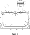
FIG. 4 is a schematic, cross-sectional view of a storage compartment in the closed position, with an enlarged schematic view of the panel structure; and -
FIG. 5 is a schematic, cross-sectional view of the storage compartment ofFIG. 4 in the open position. - Described herein is a storage compartment that provides increased usability when in a closed position, and increased storage capacity and accessibility, particularly when in an open position. The storage compartment combines bomb bay style doors with jalousie or tambour style doors to more efficiently use space within a passenger cabin of a vehicle. In an advantageous embodiment, each of the doors allows access to an interior storage area via two different sides of the storage compartment. This can provide for more convenient use of the storage compartment, while maintaining a streamlined and integrated vehicle interior appearance.
-
FIG. 1 is a partial perspective view of apassenger cabin 10 for avehicle 12 having astorage compartment 14. Thestorage compartment 14 is advantageously located between theinstrument panel 16 and thecenter console 18. This particular location is advantageous because it is oftentimes generally unused, and it provides a workingsurface 20 for either the driver or a passenger in the front. More particularly, thestorage compartment 14 is integrally built between theinstrument panel 16 and thecenter console 18 such that both the instrument panel and the center console form opposite walls orsides storage compartment 14 to be located in other locations in the vehicle, such as between passenger seats in another row of seating, to cite one potential example. Alternatively, it is also possible to have a stand-alone storage compartment 14 that is then installed between apre-existing instrument panel 16 andcenter console 18. - The
storage compartment 14 includes anexterior 26 and aninterior storage area 28. A majority of theexterior 26 is generally defined by afirst panel 30 and asecond panel 32. In a preferred embodiment, thefirst panel 30 is afirst tambour door 34 and thesecond panel 32 is asecond tambour door 36. Tambour doors are particularly useful in implementations in which there is limited space, and they have an articulated construction that permits the doors to bend as they move along a curved path. This arrangement can be particularly advantageous here, where thestorage compartment 14 is configured to allow access to theinterior storage area 28 from afirst side 38, asecond side 40, and athird side 42. In this embodiment, thedoors walls storage compartment 14 is closed. However, it should be understood that, while discussed herein in terms oftambour doors panels - In the illustrated embodiment, the first or
top side 38 of thestorage compartment 14 faces the roof of thevehicle 12, thesecond side 40 faces the driver'sdoor 44, and thethird side 42 faces the passenger's door (not shown). Thefirst side 38 is formed by the first andsecond tambour doors vehicle 12. Thesecond side 40 andthird side 42 oppose each other, and each generally form a plane that is perpendicular to the Y-axis of thevehicle 12. This arrangement allows easy access to theinterior storage area 28 from the top (i.e., the first side 38) for either a driver of thevehicle 12 or a passenger in the front seat. Further, the driver and passenger can also access theinterior storage area 28 via each different second andthird side - With reference also to
FIG. 4 , thesides bottom side 56 of thestorage compartment 14 or with the bottom side of astorage bin 84, generally form arectangular profile 46. Therectangular profile 46 includesrounded radii tambour doors FIGS. 1 and2 , therounded radius 48 is located between thefirst side 38 and thesecond side 40, and therounded radius 50 is located between the is located between thefirst side 38 and thethird side 42. With reference toFIGS. 4 and5 , therounded radius 52 is located between thesecond side 40 and a fourth orbottom side 56, and therounded radius 54 is located between thethird side 42 and thefourth side 56. Having allrounded radii tambour doors sides - The
rectangular profile 46 is also a strategically efficient use of space between theinstrument panel 16 and thecenter console 18. As shown inFIGS. 1-3 theinstrument panel 16 and thecenter console 18 provide structure to thestorage compartment 14, providing for a more integrated look and feel. However, it should be understood that thestorage compartment 14 may have other shapes, side numbers, side configurations, etc. depending on the desired implementation. For example, in some embodiments, thestorage compartment 14 could be built into another area of thevehicle 12. Thestorage compartment 14 could be located on the back of thecenter console 18, in an armrest in the rear of thevehicle 12, or in another operable location. - With particular reference to
FIGS. 4 and5 , each first andsecond door access end second door end access end 58 of thefirst door 34 meets the access end 60 of thesecond door 36 to form anopening 66. Theopening 66 advantageously biases thefirst side 38, which can provide easier access for either a driver or a passenger. Theopening 66 may include a seal, some type of closure mechanism or lock (e.g., magnets to help maintain the joining of the access ends 58, 60), or any other feature to help enhance protection of theinterior storage area 28. Additionally, a number of features can be included to enhance ease of access into theinterior storage area 28. The illustrated embodiment includes, for example, recessed handles 68, 70. Other handle arrangements (or no handles at all) may be included, but recessed handles 68, 70 provide for better articulation in the example embodiment, which includes reinforcement straps 72, 74 arranged outside of theinterior storage area 28. Accordingly, during translation of eachdoor FIG. 4 ) to the open position 78 (FIG. 5 ), the recessedhandle reinforcement strap door - The access ends 58, 60 come together to form the working
surface 20 on the first ortop side 38 of thestorage compartment 14. With reference toFIG. 2 , in the illustrated embodiments, the workingsurface 20 is large enough to comfortably hold a user's laptop (e.g., 20 inch x 20 inch). Accordingly, in at least some embodiments, the workingsurface 20 provides another raised, table-top-like surface for use from either the driver'sside seating area 80 or the passenger'sside seating area 82. The workingsurface 20 is available when thestorage compartment 14 is in theclosed position 76. However, when thestorage compartment 14 is in the open position 78 (see e.g.,FIG. 5 ), the workingsurface 20 on the first ortop side 38 is gone, in order to provide access to aninterior storage bin 84 in theinterior storage area 28. In other embodiments, the workingsurface 20 may not be as big as what is illustrated in the figures, and it may be a smaller surface located elsewhere in thecabin 10. - Each
door end respective access end exterior 26 of the storage compartment 14 (i.e., not visible within the passenger cabin 10) when in both theclosed position 76 and theopen position 78. Opposing articulating edges (not shown) may connect the opposing access ends 58, 60 and recessed ends 62, 64 to form an outer perimeter of eachdoor door closed position 76 to theopen position 78. - As shown in
FIGS. 4 and5 , when articulating between theclosed position 76 and theopen position 78, thedoors rounded radius door space 86 located between alower panel 88 and theinterior storage bin 84. In theopen position 78 shown inFIG. 5 , the recessedend 62 of thefirst door 34 overlaps the recessedend 64 of thesecond door 36 creating anoverlap region 90 where the first door, the second door, and thelower panel 88 are stacked beneath theinterior storage bin 84. In this embodiment, about two-thirds of the area of eachdoor overlap region 90, which accordingly translates to alarger opening 66 when in theopen position 78. In some embodiments, about half or more of the area of eachdoor overlap region 90. This arrangement conveniently locates the doors orpanels storage bin 84 and provides for access into theinterior storage area 28 through each of the threesides storage compartment 14. Additionally, thestorage bin 84 may have asidewall 92 that extends around the circumference of the storage bin to help retain items in the bin. Thissidewall 92 partially extends up thesides storage compartment 14. The height of thesidewall 92 of theinterior storage bin 84 can be controlled to help promote access through each of thesides sidewall 92 anddoors side open position 78. This allows for about two-thirds of eachside open position 78. In other embodiments, this area might be about half or more, in order to allow for dual side access, in addition to access through the top. Accordingly, the interiorstorage bin sidewall 92 only partially blocks thesides interior storage area 28. - With reference to enlarged partial portion of
FIG. 4 , eachdoor substrate 94 and adecorative layer 96 disposed over and coupled with the substrate. In this example, thedecorative layer 96 is coupled with the underlyingsubstrate 94 via abonding layer 98, such as an adhesive layer or a cushioning layer having its opposite sides bonded with the back side of thedecorative layer 96 and the outer side of thesubstrate 94. Thesubstrate 94 has an articulated construction while, in this example, thedecorative layer 96 is non-articulated. That is to say that thedecorative layer 96 is a solid layer with a uniform thickness relying on its own flexibility for movement with the underlying articulatedsubstrate 94. Thedecorative layer 96 presents a decorative surface to thevehicle cabin 10 and may be made from or include any number of materials, such as leather, a polymeric simulated leather, a simulated wood or metal material, or a natural material. - In one embodiment, the
decorative layer 96 includes or is a natural wood layer, such as a wood veneer, made sufficiently thin to be able to flex to follow theprofile 46 androunded radii door open positions decorative layer 96 may be non-segmented or non-articulated, with a uniform thickness along its entire length and width. In this manner, thetambour doors interior cabin 10 when the doors are in theclosed position 76. - In the illustrated example of
FIG. 4 , thesubstrate 94 of eachtambour door slats more cords 106. In this embodiment, thecord 106 is a unidirectional cord embedded in a plastic material of each one of the slats. The plastic material may be a rigid or semi-rigid plastic material comprising a thermoplastic material (e.g., ABS, PC/ABS, PP, nylon, polyester, etc.) and may additionally include fillers (e.g., glass fibers, mineral, etc.), impact modifiers, and/or other additives. Additionally, each recessedhandle slats - In yet another embodiment, each
door decorative layer 96, or a single layer structure comprising a number of lamellas for theslats decorative layer 96 is rigid or a rigid single or multi-layer substrate is used for thedoor radii doors - Reinforcement straps 72, 74 can also be included to help delimit the top or
first side 38 from the second andthird sides interior storage area 28, as shown inFIG. 3 . The reinforcement straps 72, 74 may be made of the same rigid or semi-rigid plastic material as used for the substrate 94 (e.g., ABS, PC/ABS, PP, nylon, polyester, etc., and may additionally include fillers, impact modifiers, and/or other additives). They may have a decorative covering, similar to the decorative layer or covering 96 used on eachdoor door storage compartment 14 is in theclosed position 76. In this embodiment, however, the reinforcement straps 72, 74 are visible within thepassenger cabin 10 in both theclosed position 76 and in theopen position 78. - The reinforcement straps 72, 74 can provide resting areas and additional support, particularly for larger objects within the
storage compartment 14. As illustrated inFIG. 3 , thestorage compartment 14 is configured so that multiple large items can extend partially within theinterior storage area 28 and out of the interior storage area ondifferent sides interior storage area 28 when the storage compartment is in theopen position 78. This can increase storage capacity as compared with more typical tambour door arrangements where access is only configured through one side. - It is to be understood that the foregoing is a description of one or more embodiments of the invention. The invention is not limited to the particular embodiment(s) disclosed herein, but rather is defined solely by the claims below. Furthermore, the statements contained in the foregoing description relate to particular embodiments and are not to be construed as limitations on the scope of the invention or on the definition of terms used in the claims, except where a term or phrase is expressly defined above. Various other embodiments and various changes and modifications to the disclosed embodiment(s) will become apparent to those skilled in the art. All such other embodiments, changes, and modifications are intended to come within the scope of the appended claims.
- As used in this specification and claims, the terms "e.g.," "for example," "for instance," "such as," and "like," and the verbs "comprising," "having," "including," and their other verb forms, when used in conjunction with a listing of one or more components or other items, are each to be construed as open-ended, meaning that the listing is not to be considered as excluding other, additional components or items. Other terms are to be construed using their broadest reasonable meaning unless they are used in a context that requires a different interpretation. In addition, the term "and/or" is to be construed as an inclusive OR. Therefore, for example, the phrase "A, B, and/or C" is to be interpreted as covering all the following: "A"; "B"; "C"; "A and B"; "A and C"; "B and C"; and "A, B, and C."
Claims (15)
- A storage compartment for a passenger cabin of a vehicle, comprising:a plurality of walls forming an interior storage area, the plurality of walls including an exterior comprising at least a first panel and a second panel, the first panel having an access end and the second panel having an access end,wherein the access end of the first panel and the access end of the second panel are configured to create a working surface on the exterior when in a closed position, andwherein in an open position, the first panel or the second panel is configured to allow access to the interior storage area from two or more different sides of the exterior.
- The storage compartment of claim 1, wherein the first panel is a first tambour door and the second panel is a second tambour door.
- The storage compartment of claim 1 or claim 2, wherein the two or more different sides join at a rounded radius.
- The storage compartment of any one of claims 1 to 3, wherein the two or more different sides includes a first side and a second side, with the first side configured to face a roof of the vehicle, and the second side configured to face a door of the vehicle.
- The storage compartment of claim 4, wherein the two or more different sides includes a third side, with the third side configured to face another door of the vehicle.
- The storage compartment of claim 5, wherein the first panel is configured to allow access to the interior storage area from the first side and the second side, and the second panel is configured to allow access to the interior storage area from the first side and the third side.
- The storage compartment of any one of claims 1 to 6, wherein the first panel and the second panel are configured to be placed between a center console and an instrument panel of the vehicle, whereby one of the plurality of walls is formed by, or located at, the center console and another of the plurality of walls is formed by, or located at, instrument panel.
- The storage compartment of any one of claims 1 to 7, comprising a first reinforcement strap and a second reinforcement strap, wherein the first reinforcement strap and the second reinforcement strap delimit a first side of the two or more different sides.
- The storage compartment of claim 8, wherein the first reinforcement strap and the second reinforcement strap extend between a center console and an instrument panel of the vehicle.
- The storage compartment of claim 8 or claim 9, wherein the first panel and the second panel are configured to slide under the first reinforcement strap and the second reinforcement strap, respectively, such that the first reinforcement strap and the second reinforcement strap are visible in the passenger cabin when in the closed position.
- The storage compartment of any one of claims 1 to 10, wherein the first panel and the second panel each have a recessed handle located toward the access end.
- The storage compartment of any one of claims 1 to 11, wherein the first panel has a recessed end opposite the access end and the second panel has a recessed end opposite the access end.
- The storage compartment of claim 12, wherein the recessed end of the first panel is configured to overlap the recessed end of the second panel when in the open position.
- The storage compartment of claim 13, wherein the recessed end of the first panel and the recessed end of the second panel are configured to overlap in a door space beneath an interior storage bin when in the open position.
- The storage compartment of claim 14, wherein the interior storage bin has a sidewall that partially extends up two of the two or more different sides that each face a different door of the vehicle.
Applications Claiming Priority (1)
| Application Number | Priority Date | Filing Date | Title |
|---|---|---|---|
| US17/552,484 US20230192002A1 (en) | 2021-12-16 | 2021-12-16 | Storage compartment for a passenger cabin of a vehicle |
Publications (1)
| Publication Number | Publication Date |
|---|---|
| EP4197860A1 true EP4197860A1 (en) | 2023-06-21 |
Family
ID=84537250
Family Applications (1)
| Application Number | Title | Priority Date | Filing Date |
|---|---|---|---|
| EP22213967.7A Pending EP4197860A1 (en) | 2021-12-16 | 2022-12-15 | Storage compartment for a passenger cabin of a vehicle |
Country Status (2)
| Country | Link |
|---|---|
| US (1) | US20230192002A1 (en) |
| EP (1) | EP4197860A1 (en) |
Families Citing this family (1)
| Publication number | Priority date | Publication date | Assignee | Title |
|---|---|---|---|---|
| US20220306008A1 (en) * | 2021-03-29 | 2022-09-29 | Toyoda Gosei Co., Ltd. | Double opening storage device |
Citations (6)
| Publication number | Priority date | Publication date | Assignee | Title |
|---|---|---|---|---|
| DE102009030350A1 (en) * | 2009-06-25 | 2010-12-30 | GM Global Technology Operations, Inc., Detroit | Storage compartment device for installing in e.g. interior trim of passenger motor vehicle to accommodate cups during travel, has closed storage area provided at side corresponding to opening to partially hold objects |
| US20180118121A1 (en) * | 2016-10-31 | 2018-05-03 | Inoac Usa, Inc. | Automotive interior component such as a tambour door |
| US20180222394A1 (en) | 2017-02-09 | 2018-08-09 | Ford Global Technologies, Llc | Expandable and reconfigurable console |
| DE102017112518A1 (en) * | 2017-06-07 | 2018-12-13 | Lisa Dräxlmaier GmbH | Storage compartment with holder |
| US20190193651A1 (en) * | 2017-12-21 | 2019-06-27 | Juergen Salewski | Covering device for a motor vehicle |
| DE102015113395B4 (en) * | 2015-08-13 | 2019-10-31 | Dr. Schneider Kunststoffwerke Gmbh | Device with means for opening and closing a compartment |
-
2021
- 2021-12-16 US US17/552,484 patent/US20230192002A1/en active Pending
-
2022
- 2022-12-15 EP EP22213967.7A patent/EP4197860A1/en active Pending
Patent Citations (6)
| Publication number | Priority date | Publication date | Assignee | Title |
|---|---|---|---|---|
| DE102009030350A1 (en) * | 2009-06-25 | 2010-12-30 | GM Global Technology Operations, Inc., Detroit | Storage compartment device for installing in e.g. interior trim of passenger motor vehicle to accommodate cups during travel, has closed storage area provided at side corresponding to opening to partially hold objects |
| DE102015113395B4 (en) * | 2015-08-13 | 2019-10-31 | Dr. Schneider Kunststoffwerke Gmbh | Device with means for opening and closing a compartment |
| US20180118121A1 (en) * | 2016-10-31 | 2018-05-03 | Inoac Usa, Inc. | Automotive interior component such as a tambour door |
| US20180222394A1 (en) | 2017-02-09 | 2018-08-09 | Ford Global Technologies, Llc | Expandable and reconfigurable console |
| DE102017112518A1 (en) * | 2017-06-07 | 2018-12-13 | Lisa Dräxlmaier GmbH | Storage compartment with holder |
| US20190193651A1 (en) * | 2017-12-21 | 2019-06-27 | Juergen Salewski | Covering device for a motor vehicle |
Also Published As
| Publication number | Publication date |
|---|---|
| US20230192002A1 (en) | 2023-06-22 |
Similar Documents
| Publication | Publication Date | Title |
|---|---|---|
| US7954871B2 (en) | Transparent/translucent flexible component for a vehicle interior | |
| US7234666B2 (en) | Pivoting storage bin and method of making | |
| EP1955897A1 (en) | Hinged liner for vehicle cargo area | |
| US20070046071A1 (en) | Bulkhead assembly for vehicles | |
| EP3230127B1 (en) | Vehicle armrest assembly | |
| US7828388B2 (en) | Crushable armrest assembly | |
| US7494170B2 (en) | Vehicle instrument panel having movable storage compartment | |
| US7059646B1 (en) | Cargo management system having vehicle load floor with cargo cage | |
| US7201421B2 (en) | Rear vehicle storage system | |
| US7735893B2 (en) | Overhead storage compartment for a vehicle | |
| EP4197860A1 (en) | Storage compartment for a passenger cabin of a vehicle | |
| US10232802B2 (en) | Vehicle interior panel with compressible layer of non-uniform thickness | |
| US20050116510A1 (en) | Motor vehicle roof with a center console extending in the lengthwise direction of the roof | |
| US20100264681A1 (en) | Integral structural bulkhead for cargo vans | |
| GB2422131A (en) | Vehicle trim panel with moulded cushion | |
| US6017074A (en) | Removable liner for cargo area | |
| JP2012071706A (en) | Console box | |
| US20050052045A1 (en) | Vehicle side storage box | |
| RU2703738C2 (en) | Vehicle interior trim assembly (embodiments) and vehicle (embodiments) | |
| US7183484B1 (en) | Bulkhead assembly with seal for storage compartments | |
| ES2236469T3 (en) | COATING FOR THE FLOOR OF A VEHICLE. | |
| US9987990B1 (en) | Vehicle rear cargo area structure | |
| US20210253012A1 (en) | Vehicle cooler with passenger cabin access | |
| JP7148823B2 (en) | door lining | |
| JP2001088640A (en) | Impact absorption structure of glove box for vehicle |
Legal Events
| Date | Code | Title | Description |
|---|---|---|---|
| PUAI | Public reference made under article 153(3) epc to a published international application that has entered the european phase |
Free format text: ORIGINAL CODE: 0009012 |
|
| STAA | Information on the status of an ep patent application or granted ep patent |
Free format text: STATUS: THE APPLICATION HAS BEEN PUBLISHED |
|
| AK | Designated contracting states |
Kind code of ref document: A1 Designated state(s): AL AT BE BG CH CY CZ DE DK EE ES FI FR GB GR HR HU IE IS IT LI LT LU LV MC ME MK MT NL NO PL PT RO RS SE SI SK SM TR |
|
| STAA | Information on the status of an ep patent application or granted ep patent |
Free format text: STATUS: REQUEST FOR EXAMINATION WAS MADE |
|
| 17P | Request for examination filed |
Effective date: 20231218 |
|
| RBV | Designated contracting states (corrected) |
Designated state(s): AL AT BE BG CH CY CZ DE DK EE ES FI FR GB GR HR HU IE IS IT LI LT LU LV MC ME MK MT NL NO PL PT RO RS SE SI SK SM TR |