EP4197836A1 - Vehicle door and vehicle - Google Patents
Vehicle door and vehicle Download PDFInfo
- Publication number
- EP4197836A1 EP4197836A1 EP22208727.2A EP22208727A EP4197836A1 EP 4197836 A1 EP4197836 A1 EP 4197836A1 EP 22208727 A EP22208727 A EP 22208727A EP 4197836 A1 EP4197836 A1 EP 4197836A1
- Authority
- EP
- European Patent Office
- Prior art keywords
- quadrant
- outer panel
- panel
- section
- vehicle
- Prior art date
- Legal status (The legal status is an assumption and is not a legal conclusion. Google has not performed a legal analysis and makes no representation as to the accuracy of the status listed.)
- Granted
Links
Images




Classifications
-
- B—PERFORMING OPERATIONS; TRANSPORTING
- B60—VEHICLES IN GENERAL
- B60J—WINDOWS, WINDSCREENS, NON-FIXED ROOFS, DOORS, OR SIMILAR DEVICES FOR VEHICLES; REMOVABLE EXTERNAL PROTECTIVE COVERINGS SPECIALLY ADAPTED FOR VEHICLES
- B60J5/00—Doors
- B60J5/04—Doors arranged at the vehicle sides
- B60J5/042—Reinforcement elements
- B60J5/0422—Elongated type elements, e.g. beams, cables, belts or wires
-
- B—PERFORMING OPERATIONS; TRANSPORTING
- B60—VEHICLES IN GENERAL
- B60J—WINDOWS, WINDSCREENS, NON-FIXED ROOFS, DOORS, OR SIMILAR DEVICES FOR VEHICLES; REMOVABLE EXTERNAL PROTECTIVE COVERINGS SPECIALLY ADAPTED FOR VEHICLES
- B60J5/00—Doors
- B60J5/04—Doors arranged at the vehicle sides
- B60J5/042—Reinforcement elements
- B60J5/0422—Elongated type elements, e.g. beams, cables, belts or wires
- B60J5/0423—Elongated type elements, e.g. beams, cables, belts or wires characterised by position in the lower door structure
-
- B—PERFORMING OPERATIONS; TRANSPORTING
- B60—VEHICLES IN GENERAL
- B60J—WINDOWS, WINDSCREENS, NON-FIXED ROOFS, DOORS, OR SIMILAR DEVICES FOR VEHICLES; REMOVABLE EXTERNAL PROTECTIVE COVERINGS SPECIALLY ADAPTED FOR VEHICLES
- B60J5/00—Doors
- B60J5/04—Doors arranged at the vehicle sides
- B60J5/0412—Lower door structure
- B60J5/0415—Outer panel
-
- B—PERFORMING OPERATIONS; TRANSPORTING
- B60—VEHICLES IN GENERAL
- B60J—WINDOWS, WINDSCREENS, NON-FIXED ROOFS, DOORS, OR SIMILAR DEVICES FOR VEHICLES; REMOVABLE EXTERNAL PROTECTIVE COVERINGS SPECIALLY ADAPTED FOR VEHICLES
- B60J5/00—Doors
- B60J5/04—Doors arranged at the vehicle sides
- B60J5/042—Reinforcement elements
- B60J5/0422—Elongated type elements, e.g. beams, cables, belts or wires
- B60J5/0423—Elongated type elements, e.g. beams, cables, belts or wires characterised by position in the lower door structure
- B60J5/0429—Elongated type elements, e.g. beams, cables, belts or wires characterised by position in the lower door structure the elements being arranged diagonally
-
- B—PERFORMING OPERATIONS; TRANSPORTING
- B60—VEHICLES IN GENERAL
- B60J—WINDOWS, WINDSCREENS, NON-FIXED ROOFS, DOORS, OR SIMILAR DEVICES FOR VEHICLES; REMOVABLE EXTERNAL PROTECTIVE COVERINGS SPECIALLY ADAPTED FOR VEHICLES
- B60J5/00—Doors
- B60J5/04—Doors arranged at the vehicle sides
- B60J5/042—Reinforcement elements
- B60J5/0422—Elongated type elements, e.g. beams, cables, belts or wires
- B60J5/0437—Elongated type elements, e.g. beams, cables, belts or wires characterised by the attachment means to the door, e.g. releasable attachment means
-
- B—PERFORMING OPERATIONS; TRANSPORTING
- B60—VEHICLES IN GENERAL
- B60J—WINDOWS, WINDSCREENS, NON-FIXED ROOFS, DOORS, OR SIMILAR DEVICES FOR VEHICLES; REMOVABLE EXTERNAL PROTECTIVE COVERINGS SPECIALLY ADAPTED FOR VEHICLES
- B60J5/00—Doors
- B60J5/04—Doors arranged at the vehicle sides
- B60J5/042—Reinforcement elements
- B60J5/045—Panel type elements
Definitions
- the present invention relates to a vehicle door and a vehicle.
- a vehicle door includes an outer panel on a vehicle outer side and an inner panel on a cabin side.
- the outer panel is frequently touched by persons and objects.
- a panel reinforcement as a reinforcing member is attached to an inner side of the outer panel, so as to prevent easy deformation of the outer panel (see Patent document 1).
- the present invention has a purpose of providing a vehicle door in which an outer panel is reinforced by a panel reinforcement and which is configured to generate low-frequency sound dominantly at the time of closing the door.
- the present invention may be a vehicle door having: an outer panel that is attached in an openable/closable manner to a vehicle body by a front hinge; and a panel reinforcement that extends in a vehicle front-rear direction on an inner side of the outer panel, and in which the outer panel and the panel reinforcement are fixed by plural adhesion sections, in which
- the number of the adhesion sections that are provided in the lower area and in a front lower area, which may be near the front hinge, is larger than the number of the adhesion sections that are provided in the lower area and in a rear lower area, which may be away from the front hinge.
- the front lower area may be in front of the rear lower area, and/or the front lower area may be closer to the front hinge than the rear lower area.
- the number of the adhesion sections in the upper area which is located above the concave bottom line of the belt-like concave section of the outer panel, is larger than the number of the adhesion sections in the lower area, which is located under the concave bottom line of the belt-like concave section of the outer panel.
- the number of the adhesion sections in a front lower area, which may be near the front hinge, in the lower area is larger than the number of the adhesion sections in a rear lower area, which may be away from the front hinge, in the lower area. Since the number of the adhesion sections in the upper area is larger than the number of the adhesion sections in the lower area, rigidity of the upper area is higher than rigidity of the lower area.
- the upper area of the outer panel to open/close the door when an occupant touches the upper area of the outer panel to open/close the door, the upper area is prevented from being easily deflected by an external force due to the sufficiently high rigidity.
- rigidity of the rear lower area is lower than rigidity of the front lower area.
- This rear lower area is an area where door closing sound is generated when the occupant closes the door, has the sufficiently low rigidity, and thus has a low natural vibration frequency. Accordingly, when the occupant closes the door, low-frequency sound, that is, the heavy door closing sound can be generated.
- the plural adhesion sections may exist on the concave bottom line.
- the first belt-like convex section may have:
- the number of the adhesion sections that are provided between the concave bottom line and the convex ridge line falls within the range of 70% to 90% of the number of the adhesion sections, at each of which the outer panel and the panel reinforcement adhere to each other. Therefore, the area, rigidity of which tends to be low, and which is located between the first belt-like convex section and the belt-like concave section, is sufficiently stiffened.
- the panel reinforcement may exist in a manner to expand from a front end of the outer panel toward a rear end thereof.
- the panel reinforcement exists in the manner to expand from the front end of the outer panel toward the rear end thereof. Therefore, the rigidity of the outer panel is sufficiently maintained to prevent the outer panel from being easily deflected by the external force.
- the panel reinforcement may have:
- the panel reinforcement has: the first panel reinforcement section that extends from the front end of the outer panel toward the rear end thereof; and the second panel reinforcement section that is arranged under the first panel reinforcement section and extends from the front end of the outer panel toward the rear end thereof. Therefore, even when the vehicle is subjected to a lateral collision, the rigidity of the outer panel is sufficiently maintained to prevent the outer panel from being easily deformed by the external force.
- the first panel reinforcement section may be arranged to slope downward from the front end of the outer panel toward the rear end thereof,
- the downward slope of the second panel reinforcement section is steeper than the downward slope of the first panel reinforcement section.
- a sufficiently large area where the first panel reinforcement section and the second panel reinforcement section are not fixed is secured in the rear lower area of the outer panel.
- the rear lower area has the sufficiently low rigidity, thus has the low natural vibration frequency, and easily generates the heavy door closing sound.
- a vertical length of the second belt-like convex section may be increased toward a vehicle rear side.
- the vertical length of the second belt-like convex section is increased toward the vehicle rear side.
- the area that is located between the belt-like concave section and the second belt-like convex section and has the low rigidity is increased toward the vehicle rear side. Therefore, such an area has the low natural vibration frequency and easily generates the heavy door closing sound.
- the adhesion sections may be disposed only in the first belt-like convex section and the belt-like concave section.
- the second belt-like convex section since the adhesion sections are disposed only in the first belt-like convex section and the belt-like concave section, the second belt-like convex section has the sufficiently low rigidity. For this reason, the second belt-like convex section has the low natural vibration frequency and easily generates the heavy door closing sound.
- the present invention may be a vehicle door having: an outer panel that is attached in an openable/closable manner to a vehicle body by a front hinge; and a panel reinforcement that extends in a vehicle front-rear direction on an inner side of the outer panel, and in which the outer panel and the panel reinforcement are fixed by plural adhesion sections, in which
- the number of the adhesion sections in each of the first quadrant and the second quadrant, which are located above the horizontal line passing the center of gravity of the outer panel is larger than the number of the adhesion sections in each of the third quadrant and the fourth quadrant, which are located under the horizontal line. Since the number of the adhesion sections in the first quadrant and the second quadrant is larger than the number of the adhesion sections in the third quadrant and the fourth quadrant, rigidity in the first quadrant and the second quadrant is higher than rigidity in the third quadrant and the fourth quadrant.
- the first quadrant or the second quadrant of the outer panel is prevented from being easily deflected by the external force due to the sufficiently high rigidity.
- the third quadrant and the fourth quadrant of the outer panel have the lower rigidity than the first quadrant and the second quadrant thereof, and thus has the low natural vibration frequency. Therefore, when the occupant closes the door, the heavy door closing sound can be generated in the third quadrant and the fourth quadrant.
- the number of the adhesion sections in the fourth quadrant may be larger than the number of the adhesion sections in the third quadrant.
- the rigidity in the third quadrant is lower than the rigidity in the fourth quadrant.
- This third quadrant is the area where the door closing sound is generated when the occupant closes the door, has the sufficiently low rigidity, and thus has the low natural vibration frequency. Therefore, when the occupant closes the door, the heavy door closing sound can be generated in the third quadrant.
- the panel reinforcement may have:
- the panel reinforcement has: the first panel reinforcement section that extends from the front end of the outer panel toward the rear end thereof; and the second panel reinforcement section that is arranged under the first panel reinforcement section and extends from the front end of the outer panel toward the rear end thereof. Therefore, even when the vehicle is subjected to the lateral collision, the rigidity of the outer panel is sufficiently maintained to prevent the outer panel from being easily deformed by the external force.
- the outer panel is reinforced by the panel reinforcement, and is configured to generate the low-frequency sound dominantly at the time of closing the door.
- Fig. 1 illustrates a vehicle door 100 according to a first embodiment, in particular, a front door that is seen on a right side when a vehicle (not shown) is seen forward from the rear and that is located near a driver's seat or a front passenger seat on a vehicle front side (or a vehicle front portion).
- the door 100 is coupled to a vehicle body, which is not illustrated, in a manner to be openable/closable about a vertical axis 12 and has: a substantially quadrilateral outer panel 20 that is attached in an openable/closable manner to the vehicle body by front hinges 10; a window frame 22 that is coupled on top of the outer panel 20; and a garnish attachment section 24 that is coupled to a bottom of the outer panel 20.
- the outer panel 20 may be formed by processing a steel plate having a thickness of e.g. 0.6 to 0.7 mm or an aluminum or plastic plate having substantially the same strength as the above steel plate, and may have a streamlined shape that flows rearward from the front of the vehicle from a design perspective of giving a dynamic shape to the vehicle body and a technical perspective of reducing aerodynamic drag of the vehicle body.
- the vehicle door 100 in the embodiment has three curved surfaces that are: a first belt-like convex section 202 on an upper side that is projected, in a vehicle width direction, to a vehicle outer side and extends in a vehicle front-rear direction; a belt-like concave section 204 on an intermediate side that is provided adjacent to and/or under the first belt-like convex section 202, is projected, in the vehicle width direction, to a cabin side (i.e., a vehicle inner side), and extends in the vehicle front-rear direction; and a second belt-like convex section 206 on a lower side that is provided adjacent to and/or under the belt-like concave section 204, is projected, in the vehicle width direction, to the vehicle outer side, and extends in the vehicle front-rear direction.
- Fig. 2 to Fig. 5 are cross-sectional views of the outer panel that are respectively taken along lines II-II, III-III, IV-IV, and V-V in Fig. 1 .
- a boundary between the first belt-like convex section 202 and the belt-like concave section 204 (that is, a line connecting inflection points that change from a convex curved surface to a concave curved surface) is indicated as a first inflection curve 208
- a boundary between the belt-like concave section 204 and the second belt-like convex section 206 (that is, a line connecting inflection points that change from the concave curved surface to a convex curved surface) is indicated as a second inflection curve 210.
- a line that indicates an upper edge of the first belt-like convex section 202 on the upper side may extend almost horizontally while a line that indicates a lower edge of the first belt-like convex section 202 (which is also a line that indicates an upper edge of the belt-like concave section 204) may extend to be gradually elevated from the front to the rear (from a right side to a left side of the drawing) .
- a line that indicates a lower edge of the second belt-like convex section 206 on the lower side may extend almost horizontally while a line that indicates an upper edge of the second belt-like convex section 206 (which is also a line that indicates a lower edge of the belt-like concave section 204) may extend to be gradually elevated from the front to the rear. Both of the lines that respectively indicate the upper edge and the lower edge of the belt-like concave section 204 on the intermediate side extend to be gradually elevated from the front to the rear.
- a convex ridge line 212 connecting points, each of which is most projected, in the vehicle width direction, to the vehicle outer side of a respective vertical cross section of the first belt-like convex section 202, and a concave bottom line 214 connecting points, each of which is recessed to the vehicle inner side in a respective vertical cross section of the belt-like concave section 204, may also extend to be gradually elevated from the front to the rear.
- outer surfaces of a vehicle body front portion and a rear door may be each formed with a concave-convex curved surface continuous with a concave-convex curved surface of the door 100. These concave-convex curved surfaces cooperatively create dynamic, streamlined external appearance of the vehicle.
- a front end of the second belt-like convex section 206 may be located approximately in the middle between a front end and a rear end of the front door 100, and the second belt-like convex section 206 may appear as a substantially triangular area (the second belt-like convex section 206) from the intermediate position thereof to the rear.
- the front end of the second belt-like convex section 206 may be located at the front end of the front door 100.
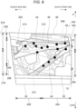
- Fig. 6 is a view in which the door 100, from which the above-described outer panel 20 is partially removed, is seen from outside of the vehicle.
- an inner panel 30 is disposed on the cabin side of the outer panel 20.
- the inner panel 30 maybe made of a metal plate, such as of iron or aluminum, or a plastic plate.
- a panel reinforcement 40 that reinforces the outer panel 20 may be arranged along an inner surface of the outer panel 20 in a manner to expand (that is, in a manner that a vertical height is gradually increased) from a front end of the outer panel 20 toward a rear end thereof (from a right side to a left side of the drawing).
- the panel reinforcement 40 mainly includes a first panel reinforcement section 42 on an upper side and a second panel reinforcement section 44 on a lower side.
- first panel reinforcement section 42 and the second panel reinforcement section 44 are each made of the metal plate, such as of iron or aluminum, or the plastic plate.
- first panel reinforcement section 42 and the second panel reinforcement section 44 may be each arranged to slope downward from the front end of the outer panel 20 toward the rear end thereof.
- the downward slope of the second panel reinforcement section 44 is set to be steeper than the downward slope of the first panel reinforcement section 42. Accordingly, an area surrounded by the first panel reinforcement section 42 and the second panel reinforcement section 44 expands toward a rear end.
- Each of the first panel reinforcement section 42 and the second panel reinforcement section 44 fixedly adheres to the outer panel 20 by plural adhesion sections 50.
- an epoxide-based adhesive or an adhesive using synthetic rubber as a material may be used as an adhesive for the adhesion sections 50.
- Each of the adhesion sections 50 may have a substantially circular shape with a diameter of approximately 30 mm.
- Fig. 6 illustrates areas of the first belt-like convex section 202, the belt-like concave section 204, the second belt-like convex section 206, the convex ridge line 212, and the concave bottom line 214, and the like so as to illustrates positional relationships among the areas and the like, each of which has been described with reference to Fig. 1 , the panel reinforcement sections 42, 44, and the adhesion sections 50.
- a front end of the first panel reinforcement section 42 on the upper side may be fixed to the outer panel 20 and, at a position near an intermediate side of a rear portion of the belt-like concave section 204, a rear end of the first panel reinforcement section 42 may be fixed to the outer panel 20.
- the first panel reinforcement section 42 may be thick in an intermediate portion between the front end and the rear end (is vertically large) and may be gradually thinned (becomes small vertically) from the intermediate portion toward each of the front end and the rear end.
- the first panel reinforcement section 42 may be arranged to diagonally cross the first inflection curve 208, which is the boundary between the first belt-like convex section 202 and the belt-like concave section 204, from the front to the rear.
- a front end of the second panel reinforcement section 44 may be fixed to the outer panel 20 and, at a position near a lower side of an intermediate portion in the front-rear direction of the second belt-like convex section 206, a rear end of the second panel reinforcement section 44 may be fixed to the outer panel 20.
- the adhesion sections 50 for the first panel reinforcement section 42 may be located between near the convex ridge line 212 of the first belt-like convex section 202 and the concave bottom line 214 of the belt-like concave section 204, and may be arranged along the first inflection curve 208, which is the boundary between the first belt-like convex section 202 and the belt-like concave section 204, or on an upper side and a lower side of the first inflection curve 208 with the first inflection curve 208 being a center.
- some of the adhesion sections 50 for the first panel reinforcement section 42 may be arranged on or near the first inflection curve 208, and thus the outer panel 20 may be strongly reinforced at such positions by the first panel reinforcement section 42.
- a door handle 222 for opening/closing the door 100 may be provided at a position near the rear end of the door 100 and near the first inflection curve 208.
- an area near the first inflection curve 208 may be an area where an occupant may frequently touch at the time of opening/closing the door, and the like.
- the area near the first inflection curve 208 may be an area that is likely to receive a shock and the like from the outside, and may also be a vulnerable area to deformation due to zero curvature thereof.
- a large number of the adhesion sections 50 may be arranged near the first inflection curve 208, and the outer panel 20 at such positions is integrated with and reinforced by the first panel reinforcement section 42.
- the number of the adhesion sections 50 for the first panel reinforcement section 42 is larger than the number of the adhesion sections 50 for the second panel reinforcement section 44.
- the nine adhesion sections 50 may be provided for the first panel reinforcement section 42 while the four adhesion sections 50 may be provided for the second panel reinforcement section 44.
- a portion of the outer panel 20 near the first inflection curve 208 may be integrated with and reinforced by the first panel reinforcement section 42 via the adhesion sections 50. Therefore, deformation of such a portion of the outer panel 20 is reliably prevented.
- the larger number of the adhesion sections 50 is provided in an upper area 216, which is located above the concave bottom line 214 of the belt-like concave section 204 of the outer panel 20, than the number of the adhesion sections 50 provided in a lower area 218, which is located under the concave bottom line 214.
- the 11 adhesion sections 50 may be arranged in the upper area 216 while the 2 adhesion sections 50 may be arranged in the lower area 218. Therefore, compared to the lower area 218, in the upper area 216, a portion of the outer panel 20 and the panel reinforcement 40 supporting such a portion of the outer panel 20 are further integrated.
- the large number of the adhesion sections 50 are provided in a front lower area 224 (see Fig. 6 ), which is located in the lower area 218 and may be near the front hinge 10, than in a rear lower area 226 (see Fig. 6 ) that may be away from the front hinge 10.
- the two adhesion sections 50 may be arranged in the front lower area 224 while the adhesion section 50 may not be arranged in the rear lower area 226. Therefore, compared to the rear lower area 226, in the front lower area 224, the portion of the outer panel 20 and the panel reinforcement 40 supporting such a portion of the outer panel 20 are further integrated.
- the lower area 218 since the rigidity of the lower area 218 is lower than that of the upper area 216, the lower area 218 generates sound at a low frequency to give a sense of luxury at the time of closing the door 100.
- the number of the adhesion sections 50 in the rear lower area 226 is smaller than the number of the adhesion sections 50 in the front lower area 224. For this reason, the sound generated from the rear lower area 226 has the lowest frequency and is the heaviest.
- Fig. 7 illustrates distribution of vibration power that is generated on the outer panel 20 at the time of closing the door 100 in the above-described embodiment.
- a darker colored portion represents the higher power.
- the vibration power in the area above the first inflection curve 208 is much lower than that in the area under the first inflection curve 208. This indicates that the rigidity of the portion of the outer panel 20 near the first inflection curve 208 is high. Accordingly, even when the large force acts on the area near the first inflection curve 208 at the time of opening/closing the door 100, or the like, or even when the shock from the outside acts thereon, the portion of the outer panel 20 near the first inflection curve 208 is not easily deformed.
- the vibration power in the lower area 218 under the first inflection curve 208 is much higher than that in the upper area 216 above the first inflection curve 208.
- the vibration power in the rear lower area 226 is higher than that in the front lower area 224.
- the lower area 218, particularly, the rear lower area 226 generates the bass sound at the time of closing the door.
- the number of the adhesion sections 50 to be arranged in this area is preferably within a range of 70% to 90% of the total number of the adhesion sections 50.
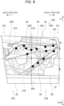
- Fig. 8 is a front view of a door that is seen on the right side of the vehicle, that is, on a side appearing as the right side when the vehicle is seen forward from the rear and that is located near the driver's seat or the front passenger seat on the vehicle front side.
- center of gravity 250 of the outer panel 20 a horizontal line 252 passing the center of gravity 250, and a vertical line 254 passing the center of gravity 250 are added to the configuration illustrated in Fig. 6 .
- a configuration of the outer panel 20 illustrated in Fig. 8 is substantially the same as the configuration of the outer panel 20 illustrated in Fig. 6 .
- the same portions or corresponding portions will be denoted by the same reference signs and numerals, and a description thereon will not be made.
- first quadrant 271 a front upper area, a rear upper area, a rear lower area, and a front lower area, which sequentially appear in a counterclockwise direction in Fig. 8 .
- first quadrant 271 a front upper area, a rear upper area, a rear lower area, and a front lower area, which sequentially appear in a counterclockwise direction in Fig. 8 .
- this terminology is used to identify four areas of the door on the vehicle right side.
- a front upper area, a rear upper area, a rear lower area, and a front lower area which sequentially appear in a clockwise direction when this door is seen from the outside, respectively correspond to the first quadrant, the second quadrant, the third quadrant, and the fourth quadrant.
- the center of gravity 250 of the outer panel 20 is substantially located at a center of the belt-like concave section 204.
- most of the first panel reinforcement section 42 on the upper side may extend obliquely downward from the front end of the door 100 toward the rear end thereof in the first quadrant 271 and the second quadrant 272, and the second panel reinforcement section 44 on the lower side extends obliquely downward from the front end of the door 100 toward the rear end thereof in the first quadrant 271, the fourth quadrant 274, and the third quadrant 273.
- Fig. 8 When Fig. 8 is seen in regard to the number of the adhesion sections 50, all of the adhesion sections 50 for the first panel reinforcement section 42 may be distributed in the first quadrant 271 and the second quadrant 272, and the number of the adhesion sections 50 in each of the first quadrant 271 and the second quadrant 272 may be almost the same. However, the number of the adhesion sections 50 provided in one of the first quadrant 271 and the second quadrant 272 may be larger than the number of the adhesion sections 50 provided in the other thereof.
- the adhesion sections 50 for the second panel reinforcement section 44 may be distributed in the first quadrant 271 and the fourth quadrant 274, and the number of the adhesion sections 50 provided in the third quadrant 273 may be zero.
- the number of the adhesion sections 50 provided in the fourth quadrant 274 is smaller than the number of the adhesion sections 50 provided in each of the first quadrant 271 and the second quadrant 272.
- the smaller number of the adhesion sections 50 than that in the fourth quadrant 274 may be provided in the third quadrant 273.
- the number of the adhesion sections 50 provided in each of the first quadrant 271 and the second quadrant 272 is larger than the number of the adhesion sections 50 provided in each of the third quadrant 273 and the fourth quadrant 274, and the number of the adhesion sections 50 provided in the fourth quadrant 274 is larger than the number of the adhesion sections 50 provided in the third quadrant 273.
- the adhesion sections 50 are arranged just as described, compared to the third quadrant 273 and the fourth quadrant 274, in the first quadrant 271 and the second quadrant 272, the outer panel 20 and the panel reinforcement 40 supporting the outer panel 20 are further integrated. In addition, compared to the third quadrant 273, in the fourth quadrant 274, the outer panel 20 and the panel reinforcement 40 supporting the outer panel 20 are further integrated.
- the rigidity of each of the first quadrant 271 and the second quadrant 272 is higher than the rigidity of each of the third quadrant 273 and the fourth quadrant 274. Therefore, even when the occupant strongly touches the first quadrant 271 or the second quadrant 272 of the outer panel 20, or even when the shock is applied thereto from the outside, the outer panel 20 is not easily deformed.
- the number of the adhesion sections 50 in the third quadrant 273 is smaller than the number of the adhesion sections 50 in each of the other first quadrant 271, second quadrant 272, and fourth quadrant 274. For this reason, the sound generated from the third quadrant 273 has the lowest frequency and is the heaviest.
- the present invention is applied to the door located near the driver's seat or the front passenger seat.
- the present invention can also be applied to a door (e.g. a rear door) which may be located near a rear seat in a similar manner.
- the present invention is not limited to the doors that are mounted on an automobile, but is also widely applicable to doors of other vehicles.
- the panel reinforcement 40 includes the two panel reinforcement sections 42, 44.
- the panel reinforcement may be formed by using a single plate material or may be formed by using three or more panel reinforcements.
Landscapes
- Engineering & Computer Science (AREA)
- Mechanical Engineering (AREA)
- Body Structure For Vehicles (AREA)
Abstract
Description
- The present invention relates to a vehicle door and a vehicle.
- A vehicle door includes an outer panel on a vehicle outer side and an inner panel on a cabin side. Of these panels, particularly, the outer panel is frequently touched by persons and objects. For this reason, a panel reinforcement as a reinforcing member is attached to an inner side of the outer panel, so as to prevent easy deformation of the outer panel (see Patent document 1).
- Meanwhile, upon designing a vehicle, it is also important to lower a frequency of sound, which is generated at the time of closing the door, so as to produce base sound and, consequently, to give the vehicle a sense of luxury. However, in the case where the panel reinforcement, which is arranged on the inner side of the outer panel, is fixed by an adhesive with a clearance being provided therebetween, a natural vibration frequency of the outer panel is increased while rigidity thereof is increased. As a result, the sound that is generated at the time of closing the door is shifted to the high-frequency side, and the sense of luxury is lost.
- [Patent document 1]
JP-A-2021-45995 - In view of the above, the present invention has a purpose of providing a vehicle door in which an outer panel is reinforced by a panel reinforcement and which is configured to generate low-frequency sound dominantly at the time of closing the door.
- The above purpose is achieved by the present invention as defined in independent claims.
- The present invention may be a vehicle door having: an outer panel that is attached in an openable/closable manner to a vehicle body by a front hinge; and a panel reinforcement that extends in a vehicle front-rear direction on an inner side of the outer panel, and in which the outer panel and the panel reinforcement are fixed by plural adhesion sections, in which
- the outer panel includes:
- a first belt-like convex section that is projected to a vehicle outer side and extends in the vehicle front-rear direction;
- a belt-like concave section that is provided under the first belt-like convex section, is projected to a cabin side, and extends in the vehicle front-rear direction; and
- a second belt-like convex section that is provided under the belt-like concave section, is projected to the vehicle outer side, and extends in the vehicle front-rear direction,
- the belt-like concave section includes:
a concave bottom line that is located between an upper end and a lower end of the belt-like concave section, is most projected to the cabin side, and extends in a front-rear direction, - the outer panel includes:
- an upper area that is located above the concave bottom line; and
- a lower area that is located under the concave bottom line,
- the number of the adhesion sections in the upper area is larger than the number of the adhesion sections in the lower area.
- The number of the adhesion sections that are provided in the lower area and in a front lower area, which may be near the front hinge, is larger than the number of the adhesion sections that are provided in the lower area and in a rear lower area, which may be away from the front hinge.
- The front lower area may be in front of the rear lower area, and/or the front lower area may be closer to the front hinge than the rear lower area.
- According to the present invention, the number of the adhesion sections in the upper area, which is located above the concave bottom line of the belt-like concave section of the outer panel, is larger than the number of the adhesion sections in the lower area, which is located under the concave bottom line of the belt-like concave section of the outer panel. In addition, the number of the adhesion sections in a front lower area, which may be near the front hinge, in the lower area is larger than the number of the adhesion sections in a rear lower area, which may be away from the front hinge, in the lower area. Since the number of the adhesion sections in the upper area is larger than the number of the adhesion sections in the lower area, rigidity of the upper area is higher than rigidity of the lower area. Accordingly, when an occupant touches the upper area of the outer panel to open/close the door, the upper area is prevented from being easily deflected by an external force due to the sufficiently high rigidity. In addition, since the number of the adhesion sections in the front lower area is larger than the number of the adhesion sections in the rear lower area, rigidity of the rear lower area is lower than rigidity of the front lower area. This rear lower area is an area where door closing sound is generated when the occupant closes the door, has the sufficiently low rigidity, and thus has a low natural vibration frequency. Accordingly, when the occupant closes the door, low-frequency sound, that is, the heavy door closing sound can be generated.
- The plural adhesion sections may exist on the concave bottom line.
- According to this configuration, since the plural adhesion sections exist on the concave bottom line, the rigidity of the belt-like concave section is sufficiently maintained.
- The first belt-like convex section may have:
- a convex ridge line that is located between an upper end and a lower end of the first belt-like convex section, is most projected to the vehicle outer side, and extends in the front-rear direction, and
- the number of the adhesion sections provided between the concave bottom line and the convex ridge line may fall within a range of 70% to 90% of the number of the adhesion sections, at each of which the outer panel and the panel reinforcement adhere to each other.
- According to this configuration, the number of the adhesion sections that are provided between the concave bottom line and the convex ridge line falls within the range of 70% to 90% of the number of the adhesion sections, at each of which the outer panel and the panel reinforcement adhere to each other. Therefore, the area, rigidity of which tends to be low, and which is located between the first belt-like convex section and the belt-like concave section, is sufficiently stiffened.
- The panel reinforcement may exist in a manner to expand from a front end of the outer panel toward a rear end thereof.
- According to this configuration, the panel reinforcement exists in the manner to expand from the front end of the outer panel toward the rear end thereof. Therefore, the rigidity of the outer panel is sufficiently maintained to prevent the outer panel from being easily deflected by the external force.
- The panel reinforcement may have:
- a first panel reinforcement section that extends from the front end of the outer panel toward the rear end thereof; and
- a second panel reinforcement section that is arranged under the first panel reinforcement section and extends from the front end of the outer panel toward the rear end thereof,
- the first panel reinforcement section may be fixed to the outer panel only by the adhesion section that is arranged in the upper area, and
- the second panel reinforcement section may be fixed to the outer panel by the adhesion sections that are arranged in the upper area and the lower area.
- According to this configuration, the panel reinforcement has: the first panel reinforcement section that extends from the front end of the outer panel toward the rear end thereof; and the second panel reinforcement section that is arranged under the first panel reinforcement section and extends from the front end of the outer panel toward the rear end thereof. Therefore, even when the vehicle is subjected to a lateral collision, the rigidity of the outer panel is sufficiently maintained to prevent the outer panel from being easily deformed by the external force.
- The first panel reinforcement section may be arranged to slope downward from the front end of the outer panel toward the rear end thereof,
- the second panel reinforcement section may be arranged to slope downward from the front end of the outer panel toward the rear end thereof, and
- the downward slope of the second panel reinforcement section may be steeper than the downward slope of the first panel reinforcement section.
- According to this configuration, the downward slope of the second panel reinforcement section is steeper than the downward slope of the first panel reinforcement section. Thus, a sufficiently large area where the first panel reinforcement section and the second panel reinforcement section are not fixed is secured in the rear lower area of the outer panel. For this reason, the rear lower area has the sufficiently low rigidity, thus has the low natural vibration frequency, and easily generates the heavy door closing sound.
- A vertical length of the second belt-like convex section may be increased toward a vehicle rear side.
- According to this configuration, the vertical length of the second belt-like convex section is increased toward the vehicle rear side. Thus, the area that is located between the belt-like concave section and the second belt-like convex section and has the low rigidity is increased toward the vehicle rear side. Therefore, such an area has the low natural vibration frequency and easily generates the heavy door closing sound.
- The adhesion sections may be disposed only in the first belt-like convex section and the belt-like concave section.
- According to this configuration, since the adhesion sections are disposed only in the first belt-like convex section and the belt-like concave section, the second belt-like convex section has the sufficiently low rigidity. For this reason, the second belt-like convex section has the low natural vibration frequency and easily generates the heavy door closing sound.
- The present invention may be a vehicle door having: an outer panel that is attached in an openable/closable manner to a vehicle body by a front hinge; and a panel reinforcement that extends in a vehicle front-rear direction on an inner side of the outer panel, and in which the outer panel and the panel reinforcement are fixed by plural adhesion sections, in which
- the outer panel is
- divided by a horizontal line and a vertical line, each of which passes a center of gravity of the outer panel, when the outer panel is seen from a vehicle outer side, and has:
- a first quadrant that is located above the horizontal line and in front of the vertical line;
- a second quadrant that is located above the horizontal line and behind the vertical line;
- a third quadrant that is located under the horizontal line and behind the vertical line; and
- a fourth quadrant that is located under the horizontal line and in front of the vertical line, and
- the number of the adhesion sections in each of the first quadrant and the second quadrant is larger than the number of the adhesion sections in each of the third quadrant and the fourth quadrant.
- According to the present invention, when the outer panel is seen from the vehicle outer side, the number of the adhesion sections in each of the first quadrant and the second quadrant, which are located above the horizontal line passing the center of gravity of the outer panel, is larger than the number of the adhesion sections in each of the third quadrant and the fourth quadrant, which are located under the horizontal line. Since the number of the adhesion sections in the first quadrant and the second quadrant is larger than the number of the adhesion sections in the third quadrant and the fourth quadrant, rigidity in the first quadrant and the second quadrant is higher than rigidity in the third quadrant and the fourth quadrant. Accordingly, when the occupant touches the first quadrant or the second quadrant of the outer panel to open/close the door, the first quadrant or the second quadrant of the outer panel is prevented from being easily deflected by the external force due to the sufficiently high rigidity. In addition, the third quadrant and the fourth quadrant of the outer panel have the lower rigidity than the first quadrant and the second quadrant thereof, and thus has the low natural vibration frequency. Therefore, when the occupant closes the door, the heavy door closing sound can be generated in the third quadrant and the fourth quadrant.
- The number of the adhesion sections in the fourth quadrant may be larger than the number of the adhesion sections in the third quadrant.
- According to this configuration, since the number of the adhesion sections in the fourth quadrant is larger than the number of the adhesion sections in the third quadrant, the rigidity in the third quadrant is lower than the rigidity in the fourth quadrant. This third quadrant is the area where the door closing sound is generated when the occupant closes the door, has the sufficiently low rigidity, and thus has the low natural vibration frequency. Therefore, when the occupant closes the door, the heavy door closing sound can be generated in the third quadrant.
- The panel reinforcement may have:
- a first panel reinforcement section that extends from the front end of the outer panel toward the rear end thereof; and
- a second panel reinforcement section that is arranged under the first panel reinforcement section and extends from the front end of the outer panel toward the rear end thereof,
- the first panel reinforcement section may be fixed to the outer panel only by the adhesion sections that are arranged in the first quadrant and the second quadrant, and
- the second panel reinforcement section may be fixed to the outer panel only by the adhesion sections that are arranged in the first quadrant and the fourth quadrant or only by the adhesion sections that are arranged in the first quadrant, the fourth quadrant and the third quadrant.
- According to this configuration, the panel reinforcement has: the first panel reinforcement section that extends from the front end of the outer panel toward the rear end thereof; and the second panel reinforcement section that is arranged under the first panel reinforcement section and extends from the front end of the outer panel toward the rear end thereof. Therefore, even when the vehicle is subjected to the lateral collision, the rigidity of the outer panel is sufficiently maintained to prevent the outer panel from being easily deformed by the external force.
- According to the present invention, the outer panel is reinforced by the panel reinforcement, and is configured to generate the low-frequency sound dominantly at the time of closing the door.
-
- [
Fig. 1] Fig. 1 is a front view in which a vehicle door according to a first embodiment of the present invention is seen from a vehicle outer side. - [
Fig. 2] Fig. 2 is a cross-sectional view of the door that is taken along line II-II inFig. 1 . - [
Fig. 3] Fig. 3 is a cross-sectional view of the door that is taken along line III-III inFig. 1 . - [
Fig. 4] Fig. 4 is a cross-sectional view of the door that is taken along line IV-IV inFig. 1 . - [
Fig. 5] Fig. 5 is a cross-sectional view of the door that is taken along line V-V inFig. 1 . - [
Fig. 6] Fig. 6 is a front view of the door inFig. 1 , from which an outer panel is partially removed. - [
Fig. 7] Fig. 7 is a distribution chart of vibration power that is generated at the time of closing the door inFig. 1 . - [
Fig. 8] Fig. 8 is a front view of a door according to a second embodiment of the present invention, from which an outer panel is partially removed. - A description will hereinafter be made on embodiments of the present invention with reference to the accompanying drawings. All of the features as shown in the drawings may not necessarily be essential.
-
Fig. 1 illustrates avehicle door 100 according to a first embodiment, in particular, a front door that is seen on a right side when a vehicle (not shown) is seen forward from the rear and that is located near a driver's seat or a front passenger seat on a vehicle front side (or a vehicle front portion). - The
door 100 is coupled to a vehicle body, which is not illustrated, in a manner to be openable/closable about avertical axis 12 and has: a substantially quadrilateralouter panel 20 that is attached in an openable/closable manner to the vehicle body by front hinges 10; awindow frame 22 that is coupled on top of theouter panel 20; and agarnish attachment section 24 that is coupled to a bottom of theouter panel 20. - The
outer panel 20 may be formed by processing a steel plate having a thickness of e.g. 0.6 to 0.7 mm or an aluminum or plastic plate having substantially the same strength as the above steel plate, and may have a streamlined shape that flows rearward from the front of the vehicle from a design perspective of giving a dynamic shape to the vehicle body and a technical perspective of reducing aerodynamic drag of the vehicle body. More specifically, thevehicle door 100 in the embodiment has three curved surfaces that are: a first belt-likeconvex section 202 on an upper side that is projected, in a vehicle width direction, to a vehicle outer side and extends in a vehicle front-rear direction; a belt-likeconcave section 204 on an intermediate side that is provided adjacent to and/or under the first belt-likeconvex section 202, is projected, in the vehicle width direction, to a cabin side (i.e., a vehicle inner side), and extends in the vehicle front-rear direction; and a second belt-likeconvex section 206 on a lower side that is provided adjacent to and/or under the belt-likeconcave section 204, is projected, in the vehicle width direction, to the vehicle outer side, and extends in the vehicle front-rear direction. -
Fig. 2 to Fig. 5 are cross-sectional views of the outer panel that are respectively taken along lines II-II, III-III, IV-IV, and V-V inFig. 1 . - Returning to
Fig. 1 , a boundary between the first belt-likeconvex section 202 and the belt-like concave section 204 (that is, a line connecting inflection points that change from a convex curved surface to a concave curved surface) is indicated as afirst inflection curve 208, and a boundary between the belt-likeconcave section 204 and the second belt-like convex section 206 (that is, a line connecting inflection points that change from the concave curved surface to a convex curved surface) is indicated as asecond inflection curve 210. - As illustrated in
Fig. 1 , a line that indicates an upper edge of the first belt-likeconvex section 202 on the upper side may extend almost horizontally while a line that indicates a lower edge of the first belt-like convex section 202 (which is also a line that indicates an upper edge of the belt-like concave section 204) may extend to be gradually elevated from the front to the rear (from a right side to a left side of the drawing) . A line that indicates a lower edge of the second belt-likeconvex section 206 on the lower side may extend almost horizontally while a line that indicates an upper edge of the second belt-like convex section 206 (which is also a line that indicates a lower edge of the belt-like concave section 204) may extend to be gradually elevated from the front to the rear. Both of the lines that respectively indicate the upper edge and the lower edge of the belt-likeconcave section 204 on the intermediate side extend to be gradually elevated from the front to the rear. Thus, aconvex ridge line 212 connecting points, each of which is most projected, in the vehicle width direction, to the vehicle outer side of a respective vertical cross section of the first belt-likeconvex section 202, and a concavebottom line 214 connecting points, each of which is recessed to the vehicle inner side in a respective vertical cross section of the belt-likeconcave section 204, may also extend to be gradually elevated from the front to the rear. - Although not illustrated, outer surfaces of a vehicle body front portion and a rear door, each of which is adjacent to the
door 100, may be each formed with a concave-convex curved surface continuous with a concave-convex curved surface of thedoor 100. These concave-convex curved surfaces cooperatively create dynamic, streamlined external appearance of the vehicle. - In the illustrated embodiment, a front end of the second belt-like
convex section 206 may be located approximately in the middle between a front end and a rear end of thefront door 100, and the second belt-likeconvex section 206 may appear as a substantially triangular area (the second belt-like convex section 206) from the intermediate position thereof to the rear. However, similarly to the first belt-likeconvex section 202 and the belt-likeconcave section 204, the front end of the second belt-likeconvex section 206 may be located at the front end of thefront door 100. -
Fig. 6 is a view in which thedoor 100, from which the above-describedouter panel 20 is partially removed, is seen from outside of the vehicle. As illustrated inFig. 6 , aninner panel 30 is disposed on the cabin side of theouter panel 20. Similarly to theouter panel 20, theinner panel 30 maybe made of a metal plate, such as of iron or aluminum, or a plastic plate. - At a position between the
outer panel 20 and theinner panel 30, apanel reinforcement 40 that reinforces theouter panel 20 may be arranged along an inner surface of theouter panel 20 in a manner to expand (that is, in a manner that a vertical height is gradually increased) from a front end of theouter panel 20 toward a rear end thereof (from a right side to a left side of the drawing). - In the embodiment, the
panel reinforcement 40 mainly includes a firstpanel reinforcement section 42 on an upper side and a secondpanel reinforcement section 44 on a lower side. - Similarly to the
outer panel 20, the firstpanel reinforcement section 42 and the secondpanel reinforcement section 44 are each made of the metal plate, such as of iron or aluminum, or the plastic plate. - In the first embodiment, the first
panel reinforcement section 42 and the secondpanel reinforcement section 44 may be each arranged to slope downward from the front end of theouter panel 20 toward the rear end thereof. The downward slope of the secondpanel reinforcement section 44 is set to be steeper than the downward slope of the firstpanel reinforcement section 42. Accordingly, an area surrounded by the firstpanel reinforcement section 42 and the secondpanel reinforcement section 44 expands toward a rear end. - Each of the first
panel reinforcement section 42 and the secondpanel reinforcement section 44 fixedly adheres to theouter panel 20 byplural adhesion sections 50. For example, an epoxide-based adhesive or an adhesive using synthetic rubber as a material may be used as an adhesive for theadhesion sections 50. Each of theadhesion sections 50 may have a substantially circular shape with a diameter of approximately 30 mm. - As illustrated,
Fig. 6 illustrates areas of the first belt-likeconvex section 202, the belt-likeconcave section 204, the second belt-likeconvex section 206, theconvex ridge line 212, and the concavebottom line 214, and the like so as to illustrates positional relationships among the areas and the like, each of which has been described with reference toFig. 1 , thepanel reinforcement sections adhesion sections 50. - It is clear from
Fig. 6 that, at a position near an intermediate side of a front portion of the first belt-likeconvex section 202, a front end of the firstpanel reinforcement section 42 on the upper side may be fixed to theouter panel 20 and, at a position near an intermediate side of a rear portion of the belt-likeconcave section 204, a rear end of the firstpanel reinforcement section 42 may be fixed to theouter panel 20. In the embodiment, the firstpanel reinforcement section 42 may be thick in an intermediate portion between the front end and the rear end (is vertically large) and may be gradually thinned (becomes small vertically) from the intermediate portion toward each of the front end and the rear end. In addition, the firstpanel reinforcement section 42 may be arranged to diagonally cross thefirst inflection curve 208, which is the boundary between the first belt-likeconvex section 202 and the belt-likeconcave section 204, from the front to the rear. - At a position near a lower side of the front portion of the first belt-like
convex section 202, a front end of the secondpanel reinforcement section 44 may be fixed to theouter panel 20 and, at a position near a lower side of an intermediate portion in the front-rear direction of the second belt-likeconvex section 206, a rear end of the secondpanel reinforcement section 44 may be fixed to theouter panel 20. - Almost all of the
adhesion sections 50 for the firstpanel reinforcement section 42 may be located between near theconvex ridge line 212 of the first belt-likeconvex section 202 and the concavebottom line 214 of the belt-likeconcave section 204, and may be arranged along thefirst inflection curve 208, which is the boundary between the first belt-likeconvex section 202 and the belt-likeconcave section 204, or on an upper side and a lower side of thefirst inflection curve 208 with thefirst inflection curve 208 being a center. In particular, some of theadhesion sections 50 for the firstpanel reinforcement section 42 may be arranged on or near thefirst inflection curve 208, and thus theouter panel 20 may be strongly reinforced at such positions by the firstpanel reinforcement section 42. - A
door handle 222 for opening/closing thedoor 100 may be provided at a position near the rear end of thedoor 100 and near thefirst inflection curve 208. Thus, an area near thefirst inflection curve 208 may be an area where an occupant may frequently touch at the time of opening/closing the door, and the like. In addition, the area near thefirst inflection curve 208 may be an area that is likely to receive a shock and the like from the outside, and may also be a vulnerable area to deformation due to zero curvature thereof. Thus, as described above, a large number of theadhesion sections 50 may be arranged near thefirst inflection curve 208, and theouter panel 20 at such positions is integrated with and reinforced by the firstpanel reinforcement section 42. - Meanwhile, almost all of the
adhesion sections 50 for the secondpanel reinforcement section 44 may be arranged in an area of the belt-likeconcave section 204, and thus may not exist in the second belt-likeconvex section 206. - In the embodiment, in regard to the number of the
adhesion sections 50, the number of theadhesion sections 50 for the firstpanel reinforcement section 42 is larger than the number of theadhesion sections 50 for the secondpanel reinforcement section 44. For example, in the embodiment, the nineadhesion sections 50 may be provided for the firstpanel reinforcement section 42 while the fouradhesion sections 50 may be provided for the secondpanel reinforcement section 44. - Just as described, in the
door 100 of the embodiment, a portion of theouter panel 20 near thefirst inflection curve 208, which is most likely to be applied with an external force, may be integrated with and reinforced by the firstpanel reinforcement section 42 via theadhesion sections 50. Therefore, deformation of such a portion of theouter panel 20 is reliably prevented. - In addition, in the
door 100 of the embodiment, the larger number of theadhesion sections 50 is provided in anupper area 216, which is located above the concavebottom line 214 of the belt-likeconcave section 204 of theouter panel 20, than the number of theadhesion sections 50 provided in alower area 218, which is located under the concavebottom line 214. For example, the 11adhesion sections 50 may be arranged in theupper area 216 while the 2adhesion sections 50 may be arranged in thelower area 218. Therefore, compared to thelower area 218, in theupper area 216, a portion of theouter panel 20 and thepanel reinforcement 40 supporting such a portion of theouter panel 20 are further integrated. - Furthermore, the large number of the
adhesion sections 50 are provided in a front lower area 224 (seeFig. 6 ), which is located in thelower area 218 and may be near thefront hinge 10, than in a rear lower area 226 (seeFig. 6 ) that may be away from thefront hinge 10. For example, the twoadhesion sections 50 may be arranged in the frontlower area 224 while theadhesion section 50 may not be arranged in the rearlower area 226. Therefore, compared to the rearlower area 226, in the frontlower area 224, the portion of theouter panel 20 and thepanel reinforcement 40 supporting such a portion of theouter panel 20 are further integrated. - For this reason, in the
outer panel 20, rigidity of theupper area 216 is higher than rigidity of thelower area 218. Therefore, even when the occupant strongly touches theupper area 216 of theouter panel 20, or even when the shock is applied thereto from the outside, theouter panel 20 is not easily deformed. - Moreover, since the rigidity of the
lower area 218 is lower than that of theupper area 216, thelower area 218 generates sound at a low frequency to give a sense of luxury at the time of closing thedoor 100. - In particular, the number of the
adhesion sections 50 in the rearlower area 226 is smaller than the number of theadhesion sections 50 in the frontlower area 224. For this reason, the sound generated from the rearlower area 226 has the lowest frequency and is the heaviest. -
Fig. 7 illustrates distribution of vibration power that is generated on theouter panel 20 at the time of closing thedoor 100 in the above-described embodiment. InFig. 7 , a darker colored portion represents the higher power. - As illustrated in
Fig. 7 , the vibration power in the area above thefirst inflection curve 208 is much lower than that in the area under thefirst inflection curve 208. This indicates that the rigidity of the portion of theouter panel 20 near thefirst inflection curve 208 is high. Accordingly, even when the large force acts on the area near thefirst inflection curve 208 at the time of opening/closing thedoor 100, or the like, or even when the shock from the outside acts thereon, the portion of theouter panel 20 near thefirst inflection curve 208 is not easily deformed. - The vibration power in the
lower area 218 under thefirst inflection curve 208 is much higher than that in theupper area 216 above thefirst inflection curve 208. In addition, when thelower area 218 is observed, the vibration power in the rearlower area 226 is higher than that in the frontlower area 224. As a result, thelower area 218, particularly, the rearlower area 226 generates the bass sound at the time of closing the door. - In the above-described embodiment, most of the
adhesion sections 50 are provided between theconvex ridge line 212 and the concavebottom line 214. However, the number of theadhesion sections 50 to be arranged in this area is preferably within a range of 70% to 90% of the total number of theadhesion sections 50. - A description will be made on a
vehicle door 100 according to a second embodiment of the present invention with reference toFig. 8 . - Similarly to
Fig. 6 ,Fig. 8 is a front view of a door that is seen on the right side of the vehicle, that is, on a side appearing as the right side when the vehicle is seen forward from the rear and that is located near the driver's seat or the front passenger seat on the vehicle front side. InFig. 8 , center ofgravity 250 of theouter panel 20, ahorizontal line 252 passing the center ofgravity 250, and avertical line 254 passing the center ofgravity 250 are added to the configuration illustrated inFig. 6 . Accordingly, a configuration of theouter panel 20 illustrated inFig. 8 is substantially the same as the configuration of theouter panel 20 illustrated inFig. 6 . Thus, the same portions or corresponding portions will be denoted by the same reference signs and numerals, and a description thereon will not be made. - In the following description, four areas that are divided by the
horizontal line 252 and thevertical line 254, that is, a front upper area, a rear upper area, a rear lower area, and a front lower area, which sequentially appear in a counterclockwise direction inFig. 8 , will respectively be referred to as afirst quadrant 271, asecond quadrant 272, athird quadrant 273, and afourth quadrant 274. - Here, this terminology is used to identify four areas of the door on the vehicle right side. Thus, in the case of an opposite front door on a vehicle left side, a front upper area, a rear upper area, a rear lower area, and a front lower area, which sequentially appear in a clockwise direction when this door is seen from the outside, respectively correspond to the first quadrant, the second quadrant, the third quadrant, and the fourth quadrant.
- As illustrated in
Fig. 8 , the center ofgravity 250 of theouter panel 20 is substantially located at a center of the belt-likeconcave section 204. In addition, most of the firstpanel reinforcement section 42 on the upper side may extend obliquely downward from the front end of thedoor 100 toward the rear end thereof in thefirst quadrant 271 and thesecond quadrant 272, and the secondpanel reinforcement section 44 on the lower side extends obliquely downward from the front end of thedoor 100 toward the rear end thereof in thefirst quadrant 271, thefourth quadrant 274, and thethird quadrant 273. - When
Fig. 8 is seen in regard to the number of theadhesion sections 50, all of theadhesion sections 50 for the firstpanel reinforcement section 42 may be distributed in thefirst quadrant 271 and thesecond quadrant 272, and the number of theadhesion sections 50 in each of thefirst quadrant 271 and thesecond quadrant 272 may be almost the same. However, the number of theadhesion sections 50 provided in one of thefirst quadrant 271 and thesecond quadrant 272 may be larger than the number of theadhesion sections 50 provided in the other thereof. - The
adhesion sections 50 for the secondpanel reinforcement section 44 may be distributed in thefirst quadrant 271 and thefourth quadrant 274, and the number of theadhesion sections 50 provided in thethird quadrant 273 may be zero. Here, the number of theadhesion sections 50 provided in thefourth quadrant 274 is smaller than the number of theadhesion sections 50 provided in each of thefirst quadrant 271 and thesecond quadrant 272. In addition, the smaller number of theadhesion sections 50 than that in thefourth quadrant 274 may be provided in thethird quadrant 273. - Just as described, in the embodiment, the number of the
adhesion sections 50 provided in each of thefirst quadrant 271 and thesecond quadrant 272 is larger than the number of theadhesion sections 50 provided in each of thethird quadrant 273 and thefourth quadrant 274, and the number of theadhesion sections 50 provided in thefourth quadrant 274 is larger than the number of theadhesion sections 50 provided in thethird quadrant 273. - Since the
adhesion sections 50 are arranged just as described, compared to thethird quadrant 273 and thefourth quadrant 274, in thefirst quadrant 271 and thesecond quadrant 272, theouter panel 20 and thepanel reinforcement 40 supporting theouter panel 20 are further integrated. In addition, compared to thethird quadrant 273, in thefourth quadrant 274, theouter panel 20 and thepanel reinforcement 40 supporting theouter panel 20 are further integrated. - For this reason, in the
outer panel 20, the rigidity of each of thefirst quadrant 271 and thesecond quadrant 272 is higher than the rigidity of each of thethird quadrant 273 and thefourth quadrant 274. Therefore, even when the occupant strongly touches thefirst quadrant 271 or thesecond quadrant 272 of theouter panel 20, or even when the shock is applied thereto from the outside, theouter panel 20 is not easily deformed. - The number of the
adhesion sections 50 in thethird quadrant 273 is smaller than the number of theadhesion sections 50 in each of the otherfirst quadrant 271,second quadrant 272, andfourth quadrant 274. For this reason, the sound generated from thethird quadrant 273 has the lowest frequency and is the heaviest. - The description has been made so far on the embodiments, in each of which the present invention is applied to the door located near the driver's seat or the front passenger seat. However, the present invention can also be applied to a door (e.g. a rear door) which may be located near a rear seat in a similar manner. In addition, the present invention is not limited to the doors that are mounted on an automobile, but is also widely applicable to doors of other vehicles.
- In the embodiments that have been described so far, the
panel reinforcement 40 includes the twopanel reinforcement sections -
- 10
- Front hinge
- 20
- Outer panel
- 40
- Panel reinforcement
- 50
- Adhesion section
- 100
- Door
- 202
- First belt-like convex section
- 204
- Belt-like concave section
- 206
- Second belt-like convex section
- 214
- Concave bottom line
- 216
- Upper area
- 218
- Lower area
- 224
- Front lower area
- 226
- Rear lower area
Claims (14)
- A vehicle door (100) having: an outer panel (20) that is attached in an openable/closable manner to a vehicle body by a front hinge (10); and a panel reinforcement (40) that extends in a vehicle front-rear direction on an inner side of the outer panel (20), and in which the outer panel (20) and the panel reinforcement (40) are fixed by plural adhesion sections (50), whereinthe outer panel (20) includes:a first belt-like convex section (202) that is projected to a vehicle outer side and extends in the vehicle front-rear direction;a belt-like concave section (204) that is provided under the first belt-like convex section (202), is projected to a cabin side, and extends in the vehicle front-rear direction; anda second belt-like convex section (206) that is provided under the belt-like concave section (204), is projected to the vehicle outer side, and extends in the vehicle front-rear direction,the belt-like concave section (204) includes:
a concave bottom line (214) that is located between an upper end and a lower end of the belt-like concave section (204), is most projected to the cabin side, and extends in the vehicle front-rear direction,the outer panel (20) includes:an upper area (216) that is located above the concave bottom line (214); anda lower area (218) that is located under the concave bottom line (214),the number of the adhesion sections (50) in the upper area (216) is larger than the number of the adhesion sections (50) in the lower area (218), andthe number of the adhesion sections (50) in a front lower area (224) in the lower area (218) is larger than the number of the adhesion sections (50) in a rear lower area (226) in the lower area (218). - The vehicle door (100) according to claim 1, whereinthe front lower area (224) is near the front hinge (10), andthe rear lower area (226) is away from the front hinge (10) .
- The vehicle door (100) according to claim 1 or 2, wherein
the plural adhesion sections (50) exist on the concave bottom line (214). - The vehicle door (100) according to any one of the preceding claims, whereinthe first belt-like convex section (202) has:
a convex ridge line (212) that is located between an upper end and a lower end of the first belt-like convex section (202), is most projected to the vehicle outer side, and extends in the vehicle front-rear direction, andthe number of the adhesion sections (50) provided between the concave bottom line (214) and the convex ridge line (212) falls within a range of 70% to 90% of the number of the adhesion sections (50), at each of which the outer panel (20) and the panel reinforcement (40) adhere to each other. - The vehicle door (100) according to any one of the preceding claims, wherein
the panel reinforcement (40) exists in a manner to expand from a front end of the outer panel (20) toward a rear end thereof. - The vehicle door (100) according to any one of the preceding claims, whereinthe panel reinforcement (40) has:a first panel reinforcement section (42) that extends from the front end of the outer panel (20) toward the rear end thereof; anda second panel reinforcement section (44) that is arranged under the first panel reinforcement section (42) and extends from the front end of the outer panel (20) toward the rear end thereof,the first panel reinforcement section (42) is fixed to the outer panel (20) only by the adhesion section (50) that is arranged in the upper area (216), andthe second panel reinforcement section (44) is fixed to the outer panel (20) by the adhesion sections (50) that are arranged in the upper area (216) and the lower area (218) .
- The vehicle door (100) according to any one of the preceding claims, whereinthe first panel reinforcement section (42) is arranged to slope downward from the front end of the outer panel (20) toward the rear end thereof,the second panel reinforcement section (44) is arranged to slope downward from the front end of the outer panel (20) toward the rear end thereof, andthe downward slope of the second panel reinforcement section (44) is steeper than the downward slope of the first panel reinforcement section (42).
- The vehicle door (100) according to any one of the preceding claims, wherein
a vertical length of the second belt-like convex section (206) is increased toward a vehicle rear side. - The vehicle door (100) according to any one of the preceding claims, wherein
the adhesion sections (50) are disposed only in the first belt-like convex section (202) and the belt-like concave section (204). - The vehicle door (100) according to any one of the preceding claims, whereinthe outer panel (20) isdivided by a horizontal line (252) and a vertical line (254), each of which passes a center of gravity (250) of the outer panel (20), when the outer panel (20) is seen from a vehicle outer side, and has:a first quadrant (271) that is located above the horizontal line (252) and in front of the vertical line (254) ;a second quadrant (272) that is located above the horizontal line (252) and behind the vertical line (254);a third quadrant (273) that is located under the horizontal line (252) and behind the vertical line (254); anda fourth quadrant (274) that is located under the horizontal line (252) and in front of the vertical line (254), andthe number of the adhesion sections (50) in each of the first quadrant (271) and the second quadrant (272) is larger than the number of the adhesion sections (50) in each of the third quadrant (273) and the fourth quadrant (274).
- A vehicle door (100) having: an outer panel (20) that is attached in an openable/closable manner to a vehicle body by a front hinge (10); and a panel reinforcement (40) that extends in a vehicle front-rear direction on an inner side of the outer panel (20), and in which the outer panel (20) and the panel reinforcement (40) are fixed by plural adhesion sections (50), whereinthe outer panel (20) isdivided by a horizontal line (252) and a vertical line (254), each of which passes a center of gravity (250) of the outer panel (20), when the outer panel (20) is seen from a vehicle outer side, and has:a first quadrant (271) that is located above the horizontal line (252) and in front of the vertical line (254) ;a second quadrant (272) that is located above the horizontal line (252) and behind the vertical line (254);a third quadrant (273) that is located under the horizontal line (252) and behind the vertical line (254); anda fourth quadrant (274) that is located under the horizontal line (252) and in front of the vertical line (254), andthe number of the adhesion sections (50) in each of the first quadrant (271) and the second quadrant (272) is larger than the number of the adhesion sections (50) in each of the third quadrant (273) and the fourth quadrant (274).
- The vehicle door (100) according to claim 10 or 11, wherein
the number of the adhesion sections (50) in the fourth quadrant (274) is larger than the number of the adhesion sections (50) in the third quadrant (273). - The vehicle door (100) according to any one of claims 10 to 12, whereinthe panel reinforcement (40) has:a first panel reinforcement section (42) that extends from a front end of the outer panel (20) toward a rear end thereof; anda second panel reinforcement section (44) that is arranged under the first panel reinforcement section (42) and extends from the front end of the outer panel (20) toward the rear end thereof,the first panel reinforcement section (42) is fixed to the outer panel (20) only by the adhesion sections (50) that are arranged in the first quadrant (271) and the second quadrant (272), andthe second panel reinforcement section (44) is fixed to the outer panel (20) only by the adhesion sections (50) that are arranged in the first quadrant (271) and the fourth quadrant (274) or only by the adhesion sections (50) that are arranged in the first quadrant (271), the fourth quadrant (274) and the third quadrant (273).
- A vehicle comprising the vehicle door (100) according to the any one of the preceding claims.
Applications Claiming Priority (1)
| Application Number | Priority Date | Filing Date | Title |
|---|---|---|---|
| JP2021202629A JP7786180B2 (en) | 2021-12-14 | 2021-12-14 | Vehicle doors |
Publications (2)
| Publication Number | Publication Date |
|---|---|
| EP4197836A1 true EP4197836A1 (en) | 2023-06-21 |
| EP4197836B1 EP4197836B1 (en) | 2025-04-23 |
Family
ID=84361092
Family Applications (1)
| Application Number | Title | Priority Date | Filing Date |
|---|---|---|---|
| EP22208727.2A Active EP4197836B1 (en) | 2021-12-14 | 2022-11-22 | Vehicle door and vehicle |
Country Status (4)
| Country | Link |
|---|---|
| US (1) | US12263725B2 (en) |
| EP (1) | EP4197836B1 (en) |
| JP (1) | JP7786180B2 (en) |
| CN (1) | CN116262428B (en) |
Families Citing this family (1)
| Publication number | Priority date | Publication date | Assignee | Title |
|---|---|---|---|---|
| CN115812045B (en) * | 2020-07-06 | 2026-01-02 | 麦格纳国际公司 | Automatic side door structure |
Citations (5)
| Publication number | Priority date | Publication date | Assignee | Title |
|---|---|---|---|---|
| DE102007026523A1 (en) * | 2006-06-09 | 2007-12-27 | Toyota Jidosha Kabushiki Kaisha, Toyota | Door e.g. front side door, arrangement for vehicle e.g. passenger car, has impact carrier and inner belt line reinforcement, which are made of steel with smaller linear extension coefficients than door outer plate |
| JP2019217939A (en) * | 2018-06-21 | 2019-12-26 | ダイハツ工業株式会社 | Door structure |
| JP2021003962A (en) * | 2019-06-25 | 2021-01-14 | 本田技研工業株式会社 | Vehicle door |
| JP2021045995A (en) | 2019-09-17 | 2021-03-25 | ダイハツ工業株式会社 | Door structure for vehicle |
| EP3892481A1 (en) * | 2019-01-15 | 2021-10-13 | Mazda Motor Corporation | Vehicle door structure |
Family Cites Families (3)
| Publication number | Priority date | Publication date | Assignee | Title |
|---|---|---|---|---|
| JP4575901B2 (en) * | 2006-03-09 | 2010-11-04 | 本田技研工業株式会社 | Vehicle door structure |
| JP4368915B2 (en) * | 2007-07-24 | 2009-11-18 | 本田技研工業株式会社 | Vehicle door structure |
| JP5949479B2 (en) * | 2012-11-14 | 2016-07-06 | マツダ株式会社 | Door mirror mounting structure |
-
2021
- 2021-12-14 JP JP2021202629A patent/JP7786180B2/en active Active
-
2022
- 2022-09-29 CN CN202211197305.7A patent/CN116262428B/en active Active
- 2022-11-22 US US18/058,136 patent/US12263725B2/en active Active
- 2022-11-22 EP EP22208727.2A patent/EP4197836B1/en active Active
Patent Citations (5)
| Publication number | Priority date | Publication date | Assignee | Title |
|---|---|---|---|---|
| DE102007026523A1 (en) * | 2006-06-09 | 2007-12-27 | Toyota Jidosha Kabushiki Kaisha, Toyota | Door e.g. front side door, arrangement for vehicle e.g. passenger car, has impact carrier and inner belt line reinforcement, which are made of steel with smaller linear extension coefficients than door outer plate |
| JP2019217939A (en) * | 2018-06-21 | 2019-12-26 | ダイハツ工業株式会社 | Door structure |
| EP3892481A1 (en) * | 2019-01-15 | 2021-10-13 | Mazda Motor Corporation | Vehicle door structure |
| JP2021003962A (en) * | 2019-06-25 | 2021-01-14 | 本田技研工業株式会社 | Vehicle door |
| JP2021045995A (en) | 2019-09-17 | 2021-03-25 | ダイハツ工業株式会社 | Door structure for vehicle |
Also Published As
| Publication number | Publication date |
|---|---|
| US12263725B2 (en) | 2025-04-01 |
| CN116262428A (en) | 2023-06-16 |
| US20230182547A1 (en) | 2023-06-15 |
| JP2023088016A (en) | 2023-06-26 |
| EP4197836B1 (en) | 2025-04-23 |
| JP7786180B2 (en) | 2025-12-16 |
| CN116262428B (en) | 2025-10-17 |
Similar Documents
| Publication | Publication Date | Title |
|---|---|---|
| EP1813454B1 (en) | Hatchback door structure for vehicles | |
| AU2007322722B2 (en) | Vehicle door structure | |
| CN102656080B (en) | Vehicle body floor structure | |
| US10300773B2 (en) | Tailgate structure | |
| US7591501B2 (en) | Hatchback door structure for vehicles | |
| US20050212333A1 (en) | Vehicle body structure | |
| EP2785577B1 (en) | Vehicle body rear structure | |
| JPH0714691B2 (en) | Rear opening / closing body structure | |
| JP5262400B2 (en) | Rear structure of the vehicle | |
| EP4197836A1 (en) | Vehicle door and vehicle | |
| CN112124053B (en) | Door for vehicle | |
| CN113401224B (en) | vehicle | |
| CN112124054B (en) | vehicle door | |
| EP2433851A1 (en) | Vehicular closure | |
| JP2020169026A (en) | Vehicle backdoor structure | |
| JP4816010B2 (en) | Vehicle door structure | |
| US9593517B2 (en) | Vehicles having load-transferring hood hinge members | |
| US20230001863A1 (en) | Sash cover assembly for a vehicle | |
| JP4305154B2 (en) | Body structure | |
| JP2013126841A (en) | Vehicle back door structure | |
| JP2009248729A (en) | Vehicular side member structure | |
| JP2021160558A (en) | Vehicular engine hood structure | |
| JP6897115B2 (en) | Reinforced structure of tailgate spoiler | |
| EP4620791A1 (en) | Truck high roof structure | |
| JP2025038600A (en) | Vehicle rear gate structure |
Legal Events
| Date | Code | Title | Description |
|---|---|---|---|
| PUAI | Public reference made under article 153(3) epc to a published international application that has entered the european phase |
Free format text: ORIGINAL CODE: 0009012 |
|
| STAA | Information on the status of an ep patent application or granted ep patent |
Free format text: STATUS: THE APPLICATION HAS BEEN PUBLISHED |
|
| AK | Designated contracting states |
Kind code of ref document: A1 Designated state(s): AL AT BE BG CH CY CZ DE DK EE ES FI FR GB GR HR HU IE IS IT LI LT LU LV MC ME MK MT NL NO PL PT RO RS SE SI SK SM TR |
|
| STAA | Information on the status of an ep patent application or granted ep patent |
Free format text: STATUS: REQUEST FOR EXAMINATION WAS MADE |
|
| 17P | Request for examination filed |
Effective date: 20231130 |
|
| RBV | Designated contracting states (corrected) |
Designated state(s): AL AT BE BG CH CY CZ DE DK EE ES FI FR GB GR HR HU IE IS IT LI LT LU LV MC ME MK MT NL NO PL PT RO RS SE SI SK SM TR |
|
| GRAP | Despatch of communication of intention to grant a patent |
Free format text: ORIGINAL CODE: EPIDOSNIGR1 |
|
| STAA | Information on the status of an ep patent application or granted ep patent |
Free format text: STATUS: GRANT OF PATENT IS INTENDED |
|
| INTG | Intention to grant announced |
Effective date: 20250109 |
|
| GRAS | Grant fee paid |
Free format text: ORIGINAL CODE: EPIDOSNIGR3 |
|
| GRAA | (expected) grant |
Free format text: ORIGINAL CODE: 0009210 |
|
| STAA | Information on the status of an ep patent application or granted ep patent |
Free format text: STATUS: THE PATENT HAS BEEN GRANTED |
|
| AK | Designated contracting states |
Kind code of ref document: B1 Designated state(s): AL AT BE BG CH CY CZ DE DK EE ES FI FR GB GR HR HU IE IS IT LI LT LU LV MC ME MK MT NL NO PL PT RO RS SE SI SK SM TR |
|
| REG | Reference to a national code |
Ref country code: GB Ref legal event code: FG4D |
|
| REG | Reference to a national code |
Ref country code: CH Ref legal event code: EP |
|
| REG | Reference to a national code |
Ref country code: DE Ref legal event code: R096 Ref document number: 602022013491 Country of ref document: DE |
|
| REG | Reference to a national code |
Ref country code: IE Ref legal event code: FG4D |
|
| REG | Reference to a national code |
Ref country code: NL Ref legal event code: MP Effective date: 20250423 |
|
| PG25 | Lapsed in a contracting state [announced via postgrant information from national office to epo] |
Ref country code: NL Free format text: LAPSE BECAUSE OF FAILURE TO SUBMIT A TRANSLATION OF THE DESCRIPTION OR TO PAY THE FEE WITHIN THE PRESCRIBED TIME-LIMIT Effective date: 20250423 |
|
| REG | Reference to a national code |
Ref country code: AT Ref legal event code: MK05 Ref document number: 1787466 Country of ref document: AT Kind code of ref document: T Effective date: 20250423 |
|
| PG25 | Lapsed in a contracting state [announced via postgrant information from national office to epo] |
Ref country code: FI Free format text: LAPSE BECAUSE OF FAILURE TO SUBMIT A TRANSLATION OF THE DESCRIPTION OR TO PAY THE FEE WITHIN THE PRESCRIBED TIME-LIMIT Effective date: 20250423 Ref country code: PT Free format text: LAPSE BECAUSE OF FAILURE TO SUBMIT A TRANSLATION OF THE DESCRIPTION OR TO PAY THE FEE WITHIN THE PRESCRIBED TIME-LIMIT Effective date: 20250825 Ref country code: ES Free format text: LAPSE BECAUSE OF FAILURE TO SUBMIT A TRANSLATION OF THE DESCRIPTION OR TO PAY THE FEE WITHIN THE PRESCRIBED TIME-LIMIT Effective date: 20250423 |
|
| REG | Reference to a national code |
Ref country code: LT Ref legal event code: MG9D |
|
| PG25 | Lapsed in a contracting state [announced via postgrant information from national office to epo] |
Ref country code: GR Free format text: LAPSE BECAUSE OF FAILURE TO SUBMIT A TRANSLATION OF THE DESCRIPTION OR TO PAY THE FEE WITHIN THE PRESCRIBED TIME-LIMIT Effective date: 20250724 Ref country code: NO Free format text: LAPSE BECAUSE OF FAILURE TO SUBMIT A TRANSLATION OF THE DESCRIPTION OR TO PAY THE FEE WITHIN THE PRESCRIBED TIME-LIMIT Effective date: 20250723 |
|
| PG25 | Lapsed in a contracting state [announced via postgrant information from national office to epo] |
Ref country code: PL Free format text: LAPSE BECAUSE OF FAILURE TO SUBMIT A TRANSLATION OF THE DESCRIPTION OR TO PAY THE FEE WITHIN THE PRESCRIBED TIME-LIMIT Effective date: 20250423 |
|
| PG25 | Lapsed in a contracting state [announced via postgrant information from national office to epo] |
Ref country code: BG Free format text: LAPSE BECAUSE OF FAILURE TO SUBMIT A TRANSLATION OF THE DESCRIPTION OR TO PAY THE FEE WITHIN THE PRESCRIBED TIME-LIMIT Effective date: 20250423 |
|
| PG25 | Lapsed in a contracting state [announced via postgrant information from national office to epo] |
Ref country code: HR Free format text: LAPSE BECAUSE OF FAILURE TO SUBMIT A TRANSLATION OF THE DESCRIPTION OR TO PAY THE FEE WITHIN THE PRESCRIBED TIME-LIMIT Effective date: 20250423 |
|
| PG25 | Lapsed in a contracting state [announced via postgrant information from national office to epo] |
Ref country code: AT Free format text: LAPSE BECAUSE OF FAILURE TO SUBMIT A TRANSLATION OF THE DESCRIPTION OR TO PAY THE FEE WITHIN THE PRESCRIBED TIME-LIMIT Effective date: 20250423 |
|
| PG25 | Lapsed in a contracting state [announced via postgrant information from national office to epo] |
Ref country code: RS Free format text: LAPSE BECAUSE OF FAILURE TO SUBMIT A TRANSLATION OF THE DESCRIPTION OR TO PAY THE FEE WITHIN THE PRESCRIBED TIME-LIMIT Effective date: 20250723 |
|
| PG25 | Lapsed in a contracting state [announced via postgrant information from national office to epo] |
Ref country code: IS Free format text: LAPSE BECAUSE OF FAILURE TO SUBMIT A TRANSLATION OF THE DESCRIPTION OR TO PAY THE FEE WITHIN THE PRESCRIBED TIME-LIMIT Effective date: 20250823 |
|
| PG25 | Lapsed in a contracting state [announced via postgrant information from national office to epo] |
Ref country code: LV Free format text: LAPSE BECAUSE OF FAILURE TO SUBMIT A TRANSLATION OF THE DESCRIPTION OR TO PAY THE FEE WITHIN THE PRESCRIBED TIME-LIMIT Effective date: 20250423 |
|
| PGFP | Annual fee paid to national office [announced via postgrant information from national office to epo] |
Ref country code: DE Payment date: 20250930 Year of fee payment: 4 |
|
| PG25 | Lapsed in a contracting state [announced via postgrant information from national office to epo] |
Ref country code: DK Free format text: LAPSE BECAUSE OF FAILURE TO SUBMIT A TRANSLATION OF THE DESCRIPTION OR TO PAY THE FEE WITHIN THE PRESCRIBED TIME-LIMIT Effective date: 20250423 Ref country code: SM Free format text: LAPSE BECAUSE OF FAILURE TO SUBMIT A TRANSLATION OF THE DESCRIPTION OR TO PAY THE FEE WITHIN THE PRESCRIBED TIME-LIMIT Effective date: 20250423 |
|
| PG25 | Lapsed in a contracting state [announced via postgrant information from national office to epo] |
Ref country code: CZ Free format text: LAPSE BECAUSE OF FAILURE TO SUBMIT A TRANSLATION OF THE DESCRIPTION OR TO PAY THE FEE WITHIN THE PRESCRIBED TIME-LIMIT Effective date: 20250423 |
|
| PG25 | Lapsed in a contracting state [announced via postgrant information from national office to epo] |
Ref country code: EE Free format text: LAPSE BECAUSE OF FAILURE TO SUBMIT A TRANSLATION OF THE DESCRIPTION OR TO PAY THE FEE WITHIN THE PRESCRIBED TIME-LIMIT Effective date: 20250423 |
|
| REG | Reference to a national code |
Ref country code: DE Ref legal event code: R097 Ref document number: 602022013491 Country of ref document: DE |
|
| PG25 | Lapsed in a contracting state [announced via postgrant information from national office to epo] |
Ref country code: SK Free format text: LAPSE BECAUSE OF FAILURE TO SUBMIT A TRANSLATION OF THE DESCRIPTION OR TO PAY THE FEE WITHIN THE PRESCRIBED TIME-LIMIT Effective date: 20250423 |
|
| PG25 | Lapsed in a contracting state [announced via postgrant information from national office to epo] |
Ref country code: IT Free format text: LAPSE BECAUSE OF FAILURE TO SUBMIT A TRANSLATION OF THE DESCRIPTION OR TO PAY THE FEE WITHIN THE PRESCRIBED TIME-LIMIT Effective date: 20250423 |
|
| PLBE | No opposition filed within time limit |
Free format text: ORIGINAL CODE: 0009261 |
|
| STAA | Information on the status of an ep patent application or granted ep patent |
Free format text: STATUS: NO OPPOSITION FILED WITHIN TIME LIMIT |
|
| REG | Reference to a national code |
Ref country code: CH Ref legal event code: L10 Free format text: ST27 STATUS EVENT CODE: U-0-0-L10-L00 (AS PROVIDED BY THE NATIONAL OFFICE) Effective date: 20260304 |
|
| PG25 | Lapsed in a contracting state [announced via postgrant information from national office to epo] |
Ref country code: RO Free format text: LAPSE BECAUSE OF FAILURE TO SUBMIT A TRANSLATION OF THE DESCRIPTION OR TO PAY THE FEE WITHIN THE PRESCRIBED TIME-LIMIT Effective date: 20250423 |
|
| 26N | No opposition filed |
Effective date: 20260126 |