EP4197832A1 - Electric vehicle thermal management loop, control method, and pure electric vehicle - Google Patents
Electric vehicle thermal management loop, control method, and pure electric vehicle Download PDFInfo
- Publication number
- EP4197832A1 EP4197832A1 EP22213081.7A EP22213081A EP4197832A1 EP 4197832 A1 EP4197832 A1 EP 4197832A1 EP 22213081 A EP22213081 A EP 22213081A EP 4197832 A1 EP4197832 A1 EP 4197832A1
- Authority
- EP
- European Patent Office
- Prior art keywords
- pipe system
- port
- power battery
- pipe
- series
- Prior art date
- Legal status (The legal status is an assumption and is not a legal conclusion. Google has not performed a legal analysis and makes no representation as to the accuracy of the status listed.)
- Granted
Links
Images


Classifications
-
- B—PERFORMING OPERATIONS; TRANSPORTING
- B60—VEHICLES IN GENERAL
- B60H—ARRANGEMENTS OF HEATING, COOLING, VENTILATING OR OTHER AIR-TREATING DEVICES SPECIALLY ADAPTED FOR PASSENGER OR GOODS SPACES OF VEHICLES
- B60H1/00—Heating, cooling or ventilating devices
- B60H1/00271—HVAC devices specially adapted for particular vehicle parts or components and being connected to the vehicle HVAC unit
- B60H1/00278—HVAC devices specially adapted for particular vehicle parts or components and being connected to the vehicle HVAC unit for the battery
-
- B—PERFORMING OPERATIONS; TRANSPORTING
- B60—VEHICLES IN GENERAL
- B60H—ARRANGEMENTS OF HEATING, COOLING, VENTILATING OR OTHER AIR-TREATING DEVICES SPECIALLY ADAPTED FOR PASSENGER OR GOODS SPACES OF VEHICLES
- B60H1/00—Heating, cooling or ventilating devices
- B60H1/00485—Valves for air-conditioning devices, e.g. thermostatic valves
-
- B—PERFORMING OPERATIONS; TRANSPORTING
- B60—VEHICLES IN GENERAL
- B60H—ARRANGEMENTS OF HEATING, COOLING, VENTILATING OR OTHER AIR-TREATING DEVICES SPECIALLY ADAPTED FOR PASSENGER OR GOODS SPACES OF VEHICLES
- B60H1/00—Heating, cooling or ventilating devices
- B60H1/00642—Control systems or circuits; Control members or indication devices for heating, cooling or ventilating devices
- B60H1/00814—Control systems or circuits characterised by their output, for controlling particular components of the heating, cooling or ventilating installation
- B60H1/00878—Control systems or circuits characterised by their output, for controlling particular components of the heating, cooling or ventilating installation the components being temperature regulating devices
- B60H1/00885—Controlling the flow of heating or cooling liquid, e.g. valves or pumps
-
- B—PERFORMING OPERATIONS; TRANSPORTING
- B60—VEHICLES IN GENERAL
- B60H—ARRANGEMENTS OF HEATING, COOLING, VENTILATING OR OTHER AIR-TREATING DEVICES SPECIALLY ADAPTED FOR PASSENGER OR GOODS SPACES OF VEHICLES
- B60H1/00—Heating, cooling or ventilating devices
- B60H1/02—Heating, cooling or ventilating devices the heat being derived from the propulsion plant
- B60H1/03—Heating, cooling or ventilating devices the heat being derived from the propulsion plant and from a source other than the propulsion plant
-
- B—PERFORMING OPERATIONS; TRANSPORTING
- B60—VEHICLES IN GENERAL
- B60H—ARRANGEMENTS OF HEATING, COOLING, VENTILATING OR OTHER AIR-TREATING DEVICES SPECIALLY ADAPTED FOR PASSENGER OR GOODS SPACES OF VEHICLES
- B60H1/00—Heating, cooling or ventilating devices
- B60H1/02—Heating, cooling or ventilating devices the heat being derived from the propulsion plant
- B60H1/14—Heating, cooling or ventilating devices the heat being derived from the propulsion plant other than from cooling liquid of the plant
- B60H1/143—Heating, cooling or ventilating devices the heat being derived from the propulsion plant other than from cooling liquid of the plant the heat being derived from cooling an electric component, e.g. electric motors, electric circuits, fuel cells or batteries
-
- B—PERFORMING OPERATIONS; TRANSPORTING
- B60—VEHICLES IN GENERAL
- B60H—ARRANGEMENTS OF HEATING, COOLING, VENTILATING OR OTHER AIR-TREATING DEVICES SPECIALLY ADAPTED FOR PASSENGER OR GOODS SPACES OF VEHICLES
- B60H1/00—Heating, cooling or ventilating devices
- B60H1/22—Heating, cooling or ventilating devices the heat source being other than the propulsion plant
- B60H1/2215—Heating, cooling or ventilating devices the heat source being other than the propulsion plant the heat being derived from electric heaters
- B60H1/2221—Heating, cooling or ventilating devices the heat source being other than the propulsion plant the heat being derived from electric heaters arrangements of electric heaters for heating an intermediate liquid
-
- B—PERFORMING OPERATIONS; TRANSPORTING
- B60—VEHICLES IN GENERAL
- B60H—ARRANGEMENTS OF HEATING, COOLING, VENTILATING OR OTHER AIR-TREATING DEVICES SPECIALLY ADAPTED FOR PASSENGER OR GOODS SPACES OF VEHICLES
- B60H1/00—Heating, cooling or ventilating devices
- B60H1/32—Cooling devices
- B60H1/3204—Cooling devices using compression
- B60H1/3228—Cooling devices using compression characterised by refrigerant circuit configurations
- B60H1/32284—Cooling devices using compression characterised by refrigerant circuit configurations comprising two or more secondary circuits, e.g. at evaporator and condenser side
-
- B—PERFORMING OPERATIONS; TRANSPORTING
- B60—VEHICLES IN GENERAL
- B60K—ARRANGEMENT OR MOUNTING OF PROPULSION UNITS OR OF TRANSMISSIONS IN VEHICLES; ARRANGEMENT OR MOUNTING OF PLURAL DIVERSE PRIME-MOVERS IN VEHICLES; AUXILIARY DRIVES FOR VEHICLES; INSTRUMENTATION OR DASHBOARDS FOR VEHICLES; ARRANGEMENTS IN CONNECTION WITH COOLING, AIR INTAKE, GAS EXHAUST OR FUEL SUPPLY OF PROPULSION UNITS IN VEHICLES
- B60K11/00—Arrangement in connection with cooling of propulsion units
- B60K11/02—Arrangement in connection with cooling of propulsion units with liquid cooling
-
- B—PERFORMING OPERATIONS; TRANSPORTING
- B60—VEHICLES IN GENERAL
- B60L—PROPULSION OF ELECTRICALLY-PROPELLED VEHICLES; SUPPLYING ELECTRIC POWER FOR AUXILIARY EQUIPMENT OF ELECTRICALLY-PROPELLED VEHICLES; ELECTRODYNAMIC BRAKE SYSTEMS FOR VEHICLES IN GENERAL; MAGNETIC SUSPENSION OR LEVITATION FOR VEHICLES; MONITORING OPERATING VARIABLES OF ELECTRICALLY-PROPELLED VEHICLES; ELECTRIC SAFETY DEVICES FOR ELECTRICALLY-PROPELLED VEHICLES
- B60L58/00—Methods or circuit arrangements for monitoring or controlling batteries or fuel cells, specially adapted for electric vehicles
- B60L58/10—Methods or circuit arrangements for monitoring or controlling batteries or fuel cells, specially adapted for electric vehicles for monitoring or controlling batteries
- B60L58/24—Methods or circuit arrangements for monitoring or controlling batteries or fuel cells, specially adapted for electric vehicles for monitoring or controlling batteries for controlling the temperature of batteries
- B60L58/26—Methods or circuit arrangements for monitoring or controlling batteries or fuel cells, specially adapted for electric vehicles for monitoring or controlling batteries for controlling the temperature of batteries by cooling
-
- B—PERFORMING OPERATIONS; TRANSPORTING
- B60—VEHICLES IN GENERAL
- B60L—PROPULSION OF ELECTRICALLY-PROPELLED VEHICLES; SUPPLYING ELECTRIC POWER FOR AUXILIARY EQUIPMENT OF ELECTRICALLY-PROPELLED VEHICLES; ELECTRODYNAMIC BRAKE SYSTEMS FOR VEHICLES IN GENERAL; MAGNETIC SUSPENSION OR LEVITATION FOR VEHICLES; MONITORING OPERATING VARIABLES OF ELECTRICALLY-PROPELLED VEHICLES; ELECTRIC SAFETY DEVICES FOR ELECTRICALLY-PROPELLED VEHICLES
- B60L58/00—Methods or circuit arrangements for monitoring or controlling batteries or fuel cells, specially adapted for electric vehicles
- B60L58/10—Methods or circuit arrangements for monitoring or controlling batteries or fuel cells, specially adapted for electric vehicles for monitoring or controlling batteries
- B60L58/24—Methods or circuit arrangements for monitoring or controlling batteries or fuel cells, specially adapted for electric vehicles for monitoring or controlling batteries for controlling the temperature of batteries
- B60L58/27—Methods or circuit arrangements for monitoring or controlling batteries or fuel cells, specially adapted for electric vehicles for monitoring or controlling batteries for controlling the temperature of batteries by heating
-
- H—ELECTRICITY
- H01—ELECTRIC ELEMENTS
- H01M—PROCESSES OR MEANS, e.g. BATTERIES, FOR THE DIRECT CONVERSION OF CHEMICAL ENERGY INTO ELECTRICAL ENERGY
- H01M10/00—Secondary cells; Manufacture thereof
- H01M10/60—Heating or cooling; Temperature control
- H01M10/61—Types of temperature control
- H01M10/613—Cooling or keeping cold
-
- H—ELECTRICITY
- H01—ELECTRIC ELEMENTS
- H01M—PROCESSES OR MEANS, e.g. BATTERIES, FOR THE DIRECT CONVERSION OF CHEMICAL ENERGY INTO ELECTRICAL ENERGY
- H01M10/00—Secondary cells; Manufacture thereof
- H01M10/60—Heating or cooling; Temperature control
- H01M10/61—Types of temperature control
- H01M10/615—Heating or keeping warm
-
- H—ELECTRICITY
- H01—ELECTRIC ELEMENTS
- H01M—PROCESSES OR MEANS, e.g. BATTERIES, FOR THE DIRECT CONVERSION OF CHEMICAL ENERGY INTO ELECTRICAL ENERGY
- H01M10/00—Secondary cells; Manufacture thereof
- H01M10/60—Heating or cooling; Temperature control
- H01M10/62—Heating or cooling; Temperature control specially adapted for specific applications
- H01M10/625—Vehicles
-
- H—ELECTRICITY
- H01—ELECTRIC ELEMENTS
- H01M—PROCESSES OR MEANS, e.g. BATTERIES, FOR THE DIRECT CONVERSION OF CHEMICAL ENERGY INTO ELECTRICAL ENERGY
- H01M10/00—Secondary cells; Manufacture thereof
- H01M10/60—Heating or cooling; Temperature control
- H01M10/63—Control systems
- H01M10/635—Control systems based on ambient temperature
-
- H—ELECTRICITY
- H01—ELECTRIC ELEMENTS
- H01M—PROCESSES OR MEANS, e.g. BATTERIES, FOR THE DIRECT CONVERSION OF CHEMICAL ENERGY INTO ELECTRICAL ENERGY
- H01M10/00—Secondary cells; Manufacture thereof
- H01M10/60—Heating or cooling; Temperature control
- H01M10/63—Control systems
- H01M10/637—Control systems characterised by the use of reversible temperature-sensitive devices, e.g. NTC, PTC or bimetal devices; characterised by control of the internal current flowing through the cells, e.g. by switching
-
- H—ELECTRICITY
- H01—ELECTRIC ELEMENTS
- H01M—PROCESSES OR MEANS, e.g. BATTERIES, FOR THE DIRECT CONVERSION OF CHEMICAL ENERGY INTO ELECTRICAL ENERGY
- H01M10/00—Secondary cells; Manufacture thereof
- H01M10/60—Heating or cooling; Temperature control
- H01M10/65—Means for temperature control structurally associated with the cells
- H01M10/655—Solid structures for heat exchange or heat conduction
- H01M10/6556—Solid parts with flow channel passages or pipes for heat exchange
-
- H—ELECTRICITY
- H01—ELECTRIC ELEMENTS
- H01M—PROCESSES OR MEANS, e.g. BATTERIES, FOR THE DIRECT CONVERSION OF CHEMICAL ENERGY INTO ELECTRICAL ENERGY
- H01M10/00—Secondary cells; Manufacture thereof
- H01M10/60—Heating or cooling; Temperature control
- H01M10/65—Means for temperature control structurally associated with the cells
- H01M10/656—Means for temperature control structurally associated with the cells characterised by the type of heat-exchange fluid
- H01M10/6567—Liquids
- H01M10/6568—Liquids characterised by flow circuits, e.g. loops, located externally to the cells or cell casings
-
- H—ELECTRICITY
- H01—ELECTRIC ELEMENTS
- H01M—PROCESSES OR MEANS, e.g. BATTERIES, FOR THE DIRECT CONVERSION OF CHEMICAL ENERGY INTO ELECTRICAL ENERGY
- H01M10/00—Secondary cells; Manufacture thereof
- H01M10/60—Heating or cooling; Temperature control
- H01M10/65—Means for temperature control structurally associated with the cells
- H01M10/656—Means for temperature control structurally associated with the cells characterised by the type of heat-exchange fluid
- H01M10/6569—Fluids undergoing a liquid-gas phase change or transition, e.g. evaporation or condensation
-
- H—ELECTRICITY
- H01—ELECTRIC ELEMENTS
- H01M—PROCESSES OR MEANS, e.g. BATTERIES, FOR THE DIRECT CONVERSION OF CHEMICAL ENERGY INTO ELECTRICAL ENERGY
- H01M10/00—Secondary cells; Manufacture thereof
- H01M10/60—Heating or cooling; Temperature control
- H01M10/65—Means for temperature control structurally associated with the cells
- H01M10/657—Means for temperature control structurally associated with the cells by electric or electromagnetic means
- H01M10/6571—Resistive heaters
-
- H—ELECTRICITY
- H01—ELECTRIC ELEMENTS
- H01M—PROCESSES OR MEANS, e.g. BATTERIES, FOR THE DIRECT CONVERSION OF CHEMICAL ENERGY INTO ELECTRICAL ENERGY
- H01M10/00—Secondary cells; Manufacture thereof
- H01M10/60—Heating or cooling; Temperature control
- H01M10/66—Heat-exchange relationships between the cells and other systems, e.g. central heating systems or fuel cells
- H01M10/663—Heat-exchange relationships between the cells and other systems, e.g. central heating systems or fuel cells the system being an air-conditioner or an engine
-
- B—PERFORMING OPERATIONS; TRANSPORTING
- B60—VEHICLES IN GENERAL
- B60H—ARRANGEMENTS OF HEATING, COOLING, VENTILATING OR OTHER AIR-TREATING DEVICES SPECIALLY ADAPTED FOR PASSENGER OR GOODS SPACES OF VEHICLES
- B60H1/00—Heating, cooling or ventilating devices
- B60H1/00271—HVAC devices specially adapted for particular vehicle parts or components and being connected to the vehicle HVAC unit
- B60H2001/00307—Component temperature regulation using a liquid flow
-
- Y—GENERAL TAGGING OF NEW TECHNOLOGICAL DEVELOPMENTS; GENERAL TAGGING OF CROSS-SECTIONAL TECHNOLOGIES SPANNING OVER SEVERAL SECTIONS OF THE IPC; TECHNICAL SUBJECTS COVERED BY FORMER USPC CROSS-REFERENCE ART COLLECTIONS [XRACs] AND DIGESTS
- Y02—TECHNOLOGIES OR APPLICATIONS FOR MITIGATION OR ADAPTATION AGAINST CLIMATE CHANGE
- Y02E—REDUCTION OF GREENHOUSE GAS [GHG] EMISSIONS, RELATED TO ENERGY GENERATION, TRANSMISSION OR DISTRIBUTION
- Y02E60/00—Enabling technologies; Technologies with a potential or indirect contribution to GHG emissions mitigation
- Y02E60/10—Energy storage using batteries
-
- Y—GENERAL TAGGING OF NEW TECHNOLOGICAL DEVELOPMENTS; GENERAL TAGGING OF CROSS-SECTIONAL TECHNOLOGIES SPANNING OVER SEVERAL SECTIONS OF THE IPC; TECHNICAL SUBJECTS COVERED BY FORMER USPC CROSS-REFERENCE ART COLLECTIONS [XRACs] AND DIGESTS
- Y02—TECHNOLOGIES OR APPLICATIONS FOR MITIGATION OR ADAPTATION AGAINST CLIMATE CHANGE
- Y02T—CLIMATE CHANGE MITIGATION TECHNOLOGIES RELATED TO TRANSPORTATION
- Y02T10/00—Road transport of goods or passengers
- Y02T10/60—Other road transportation technologies with climate change mitigation effect
- Y02T10/70—Energy storage systems for electromobility, e.g. batteries
Definitions
- the present invention belongs to a technical field of thermal management of a whole vehicle of a new energy vehicle, and especially to an electric vehicle thermal management loop, a control method, and a pure electric vehicle.
- New energy vehicles become a main development direction in an automotive industry.
- Current new energy vehicles are mainly pure electric and hydrogen fueled vehicles.
- Pure electric vehicles are limited by current battery material characteristics and capacity bottleneck, endurance of pure electric vehicles cannot have equivalent endurance of traditional fuel vehicles, especially the endurance in low-temperature environment in winter, which is also a main concern of consumers over pure electric vehicles.
- Both a passenger compartment and a power battery need to be heated in a low-temperature environment in winter.
- a heating source is generally realized through PTC.
- electric heating efficiency of PTC is only about 0.95. Therefore, in the low-temperature environment, a level of the heating energy consumption of the pure electric vehicle directly affects the endurance of the whole vehicle.
- energy consumption of temperature control of power batteries is large, which affects vehicle endurance and fails to meet actual demands.
- an objective of the present invention is to provide a thermal management loop of an electric vehicle, a control method, and a pure electric vehicle, which use thermal coupling of heating pump, cooling loops of driving motor, and thermal management loops of a power battery to achieve efficient thermal management of a whole vehicle and reduce energy consumption of the whole vehicle.
- the present invention provides a thermal management loop of an electric vehicle, comprising:
- a passenger compartment temperature control pipe system which comprises an electric compressor, an outdoor heat exchanger, an evaporator, a gas-liquid separator, an in-vehicle condenser, and a heat exchange pipe, and A second control pipe system, configured to enable the passenger compartment temperature control pipe system to switch between the following two states:
- the first control pipe system is configured to enable the motor cooling pipe system and the power battery temperature control pipe system to be switched to state 4;
- the first control pipe system comprises a four-way valve, a first three-way valve, and a second three-way valve;
- the second control pipe system comprises:
- the first sub-pipe system is provided with a first electronic expansion valve, which is located at a liquid outlet end of the in-vehicle condenser;
- the power battery temperature control pipe system is provided with a first PTC heater, which is located between the second water pump and the battery cooler; the evaporator and the in-vehicle condenser are both located in an air duct of a vehicle air conditioning system; and a second PTC heater is disposed in the air duct of the vehicle air conditioning system.
- the present invention also provides a control method for an electric vehicle thermal management loop
- the electric vehicle thermal management loop comprises a driving motor cooling pipe system, a power battery temperature control pipe system, and a passenger compartment temperature control pipe system
- the driving motor cooling pipe system comprises an expansion kettle, a first water pump, a driving motor, and a low-temperature radiator connected in sequence
- the power battery temperature control pipe system comprises a second water pump, a first PTC heater, a battery cooler, and a power battery connected in sequence
- the passenger compartment temperature control pipe system comprises an electric compressor, an outdoor heat exchanger, an evaporator, a gas-liquid separator, an in-vehicle condenser, a heat exchange pipe, and a second PTC heater
- the heat exchange pipe passes through the battery cooler to realize heat exchange with the power battery temperature control pipe system
- the control method comprises:
- the present invention also provides a pure electric vehicle, comprising:
- the electric vehicle thermal management loop also comprises a third pipe system, which comprises a third water pump, a PTC heater, and a heater core connected in series, the heater core is located in an air duct of a vehicle air conditioning system, and the heater core is connected in parallel with both ends of the power battery;
- the third pipe system is provided with a second reversing module, and the second reversing module is configured to enable the third pipe system to switch among following three stations:
- the third pipe system is connected in series with a water-cooled condenser
- the water-cooled condenser comprises a flow channel a and a flow channel b
- the flow channel a and the flow channel b are independent from each other and are able to conduct heat exchange therebetween
- the flow channel a is connected in series with the third-pipe system
- the flow channel b is connected to a high-temperature pipe of the vehicle air conditioning system
- the vehicle air conditioning system comprises an electric compressor, an outdoor heat exchanger, an evaporator, and a gas-liquid separator connected to each other
- the vehicle air conditioning system also comprises a third reversing module, which is configured to enable the vehicle air conditioning system to switch between the following two stations:
- the first reversing module is configured to enable the first pipe system and the second pipe system to be switched to station 5, and the station 5 means that: the expansion kettle, the first water pump, and the driving motor form a closed loop separately; the second water pump and the power battery form a closed loop separately.
- the electric compressor, the outdoor heat exchanger, the evaporator, and the gas-liquid separator are connected in series on a main pipe system, and the main pipe system is a closed loop; one end of the flow channel b is connected to one main pipe system between the electric compressor and the outdoor heat exchanger, and another end of the flow channel b is connected to the main pipe system between the outdoor heat exchanger and the evaporator; and both ends of the second flow channel are respectively connected to both ends of the evaporator;
- the third reversing module comprises:
- the vehicle air conditioning system also comprises a first electronic expansion valve located on a pipe leading from the flow channel b to the outdoor heat exchanger under the status of station II;
- the first reversing module comprises a six-way valve, a first branch pipe, and a second branch pipe;
- the present invention realizes series and parallel operations of the electric vehicle driving motor cooling loop and the power battery cooling loop, which not only enables the power battery to be cooled or heated separately, but also uses heat generated by the motor to heat the power battery, realizes energy recovery and utilization, and reduces vehicle energy consumption.
- the present invention can bypass the power battery, thermally couple a water loop and a cooling loop, thereby transferring the heat generated by the motor to the passenger compartment, realizing auxiliary heating of the passenger compartment, and reducing energy consumption of the air conditioning system.
- the present invention can realize reversing function of cooling and heating conditions of the outdoor heat exchanger through simple control, effectively reduce the energy consumption of the systems and improve battery endurance on a premise of meeting cooling and heating demands.
- the present invention can use the cooling loop of the driving motor to cool the power battery, and can effectively reduce load of the air conditioning system when cooling demand of the power battery is not high.
- the present invention can use the air conditioning system to cool the power battery, and can effectively improve cooling efficiency when the power battery cooling demand is high.
- the present invention can use the PTC heater to heat the power battery, and can effectively improve the heating efficiency when the power battery has a high heating demand.
- the present invention realizes the series and parallel operations of the driving motor cooling loop and the power battery cooling loop of the electric vehicle, the low-temperature radiator of the bypass driving motor loop, the bypass power battery, the thermal coupling of the water loop and the cooling loop, the bypass of the passenger compartment heat exchanger, the reversing of the cooling and heating conditions of the outdoor heat exchanger, the use of heat pumps for heating the power battery and other functions. While ensuring the temperature control efficiency, the present invention can reduce energy consumption of the systems and improve vehicle endurance.
- an electric vehicle thermal management loop comprises a driving motor cooling pipe system, a power battery temperature control pipe system, a passenger compartment temperature control pipe system, a first control pipe system, and a second control pipe system.
- the driving motor cooling pipe system comprises an expansion kettle 11, a first water pump 12, a driving motor 13, and a low-temperature radiator 14 connected in sequence.
- the driving motor 13 in the present invention refers to a cooling water channel of the driving motor 13, not the power structure of the driving motor 13 itself.
- the power battery temperature control pipe system comprises a second water pump 21, a first PTC heater 22, a battery cooler 23, and a power battery 24 connected in sequence.
- the power battery 24 of the present invention refers to a cooling channel of the power battery 24, not the electrochemical structure of the power battery 24 itself.
- the passenger compartment temperature control pipe system comprises an electric compressor 41, an outdoor heat exchanger 42, an evaporator 43, a gas-liquid separator 44, an in-vehicle condenser 45, a heat exchange pipe 46, and a second PTC heater 47.
- the heat exchange pipe 46 passes through the battery cooler 23 to realize heat exchange with the power battery temperature control pipe system.
- the evaporator 43, the in-vehicle condenser 45, and the second PTC heater 47 are all located in the air duct of the vehicle air conditioning system.
- the low-temperature radiator 14 and the outdoor heat exchanger 42 are both located behind a grille 71 on a front face of the vehicle, and the low-temperature radiator 14 is located in front of the outdoor heat exchanger 42, and a cooling fan 72 is disposed a rear side of the outdoor heat exchanger 42.
- the first control pipe system is located between the driving motor cooling pipe system and the power battery temperature control pipe system.
- the first control pipe system is configured to enable the driving motor cooling pipe system and the power battery temperature control pipe system to switch among following four states:
- the above four states can be selectively set, for example, only state 1, state 2, and state 3 can be set.
- the first control pipe system comprises a six-way valve 31, which comprises:
- the six-way valve 31 is configured to be able to switch among at least following four working stations:
- the station 1, the station 2, the station 3, and the station 4 of the six-way valve 31 respectively realize the state 1, the state 2, the state 3, and the state 4.
- the second control pipe system is configured to enable the passenger compartment temperature control pipe system to switch between the following two states:
- the second control pipe system comprises:
- the passenger compartment temperature control pipe system is in a refrigeration state.
- the passenger compartment temperature control pipe system is in a heating state.
- the communication with or disconnection of the second sub-pipe system 402 is related to heat exchange between the passenger compartment temperature control pipe system and the power battery temperature control pipe system.
- Effects of the heat exchange are mainly in two aspects.
- the power battery 24 is cooled simultaneously during a cooling process of the passenger compartment temperature control pipe system; and on the other hand, the power battery temperature control pipe system absorbs heat generated by the motor during a heating process of the passenger compartment temperature control pipe system, thereby improving the heating effect of the passenger compartment temperature control pipe system, realizing energy recovery and reducing heating energy consumption.
- the first control valve assembly comprises:
- the two-way solenoid valves of the present invention are stop valves, the stop valve has two stations of conduction and disconnection.
- the stop valve has two stations of conduction and disconnection.
- the second control valve assembly comprises a third two-way solenoid valve 53 disposed on the third sub-pipe system 403.
- a first electronic expansion valve 54 is disposed on the first sub-pipe system 401, and the first electronic expansion valve 54 is located at an outlet end of the in-vehicle condenser 45.
- a second electronic expansion valve 56 is disposed on the second sub-pipe system 402, and the second electronic expansion valve 56 is located at an inlet end of the heat exchange pipe 46.
- a third electronic expansion valve 55 is disposed at an inlet end of the evaporator 43.
- the present invention can realize independent control of the in-vehicle condenser 45, the evaporator 43, and heat exchange pipe 46 through the above electronic expansion valves, so as to finely control the pipe systems according to actual temperature control demands.
- the main pipe system 400 is provided with a one-way valve 57, which is located on the main pipe system 400 between the first sub-pipe system 401 and the second sub-pipe system 402.
- the following positions are provided with temperature sensors: an outlet of the electric compressor 41, a surface of the outdoor heat exchanger 42, a suction port of the electric compressor 41, a surface of the evaporator 43, an inlet of the driving motor 13, and an inlet of the power battery 24.
- an outlet of the in-vehicle condenser 45 and an outlet of the evaporator 43 are provided with pressure sensors and temperature sensors.
- temperature sensors and pressure temperature sensors can be connected to a trip computer or an independent controller, so as to adjust operation status of the pipe systems in real time according to ambient temperature and pipe operation parameters.
- the present invention also provides a control method of the electric vehicle thermal management loop, comprises: controlling the driving motor cooling pipe system and the power battery temperature control pipe system to form independent closed loops respectively, when both the passenger compartment and the power battery 24 have cooling requirements; controlling the electric compressor 41, the outdoor heat exchanger 42, the evaporator 43, and the gas-liquid separator 44 to be connected in series in sequence to form a closed loop, and the heat exchange pipe 46 is connected in parallel with the evaporator 43; controlling the first PTC heater 22 to close; this working condition is often used in hot summer environment, for example, when the ambient temperature is greater than 30 ° C.
- the present invention can improve heating efficiency of the power battery 24 and the passenger compartment through a first PTC heater 22 and a second PTC heater 47.
- a difference between the present embodiment and the embodiment 1 is that only specific embodiments of the first control pipe system and the first control valve assembly are different.
- the first control pipe system comprises a four-way valve 34, a first three-way valve 35, and a second three-way valve 37;
- the first control valve assembly comprises a third three-way valve 58, which is located at a connection node between a front end of the first sub-pipe 401 and the main pipe 400.
- a difference between the present embodiment and embodiment 1 is that only the specific implementation methods of the first control valve assembly are different.
- the first control valve assembly comprises a third three-way valve 58, which is located at a connection node between a front end of the first sub pipe system 401 and the main pipe system 400.
- the present invention realizes a series parallel operation of the cooling loop of the driving motor 13 and the cooling loop of the power battery 24 of the electric vehicle, the low-temperature radiator 14 of the loop of the bypass driving motor 13, the bypass power battery 24, the thermal coupling of the water loop and the refrigerant loop, the bypass of the heat exchanger in the passenger compartment, the reversing of the cooling and heating conditions of the outdoor heat exchanger 42, and effectively reduces energy consumption of the system and improves battery life on a premise of meeting cooling and heating demands .
- an electric vehicle thermal management loop comprises a first pipe system 10', a second pipe system 20', and a first reversing module.
- the first pipe system 10' comprises an expansion kettle 11', a first water pump 12', a driving motor 13', and a low-temperature radiator 14' which are connected in series.
- the second pipe system 20' comprises a second water pump 21', a power battery 22', and a battery cooler 23' connected in series.
- the first reversing module is connected between the first pipe system 10' and the second pipe system 20'.
- the first reversing module is configured to enable the first pipe system 10' and the second pipe system 20' to switch among the following four stations:
- the battery cooler 23' comprises a first flow channel 231' and a second flow channel 232'.
- the first flow channel 231' and the second flow channel 232' are independent with each other and can conduct heat exchange therebetween.
- the first flow channel 231' is connected in series to the second pipe system 20', and the second flow channel 232' is connected to the low-temperature pipe of the vehicle air conditioning system.
- the driving motor 13' refers to the cooling water loop of the driving motor 13', not the power structure of the driving motor 13' itself.
- the power battery 22' refers to the cooling water loop of the power battery 22', not the electrochemical structure of the power battery 22'.
- the present invention can selectively connect the power battery 22' to the air conditioning system or the driving motor 13'.
- the battery When connected to the air conditioning system, the battery is cooled.
- cooling liquid of the driving motor 13' can be used to cool the battery; on the other hand, residual heat of the driving motor 13' can be used to heat the battery and reduce system energy consumption.
- the present invention can directly conduct heat exchange between the cooling liquid of the driving motor 13' and the air conditioning system, and can absorb residual heat of the driving motor 13' when the air conditioning system is in heating, thereby reducing the system energy consumption while ensuring the heating effect.
- the third pipe system 30' comprises a third water pump 31', a PTC heater 32', and a heating core 33' connected in series.
- the heating core 33' is located in an air duct of the vehicle air conditioning system, and the heating core 33' is connected in parallel to both ends of the power battery 22';
- the third pipe 30' is provided with a second reversing module, and the second reversing module is configured to enable the third pipe system 30' to switch among following three stations:
- the second reversing module in the present invention can be a three-way proportional valve 301', for example. It can be foreseen that the present invention can also use two stop valves to replace the three-way proportional valve 301'.
- the present invention can also auxiliarily heat the power battery 22' and the passenger compartment through the PTC heater 32', so as to ensure that the power battery 22' works at a suitable temperature and improve electric energy conversion rate.
- the third pipe system 30' is connected in series with a water-cooled condenser 34'.
- the water-cooled condenser 34' comprises a flow channel a341' and a flow channel b342'.
- the flow channel a341' and the flow channel b342' are independent with each other and can conduct heat exchange therebetween.
- the flow channel a341' is connected in series with the third pipe system 30', and the flow channel b 342' is connected to high-temperature pipe of the vehicle air conditioning system.
- the present invention can realize the heat exchange between the third pipe system 30' and the air conditioning system.
- the air conditioning system can be used to heat the passenger compartment.
- the air conditioning system can recover residual heat of the driving motor 13', which reduces the system energy consumption while ensuring heating effect of the passenger compartment.
- the vehicle air conditioning system comprises an electric compressor 41', an outdoor heat exchanger 42', an evaporator 43', and a gas-liquid separator 44' connected to each other; it also comprises a third reversing module, which is configured to enable the vehicle air conditioning system to switch between the following two stations:
- the above station I corresponds to the cooling state of the air conditioner
- the above station II corresponds to the heating state of the air conditioner
- the first reversing module is configured to enable the first pipe system 10' and the second pipe system 20' to be switched to station 5, the station 5 is: the expansion kettle 11', the first water pump 12', and the driving motor 13' form a closed loop independently; the second water pump 21' and the power battery 22' form a closed loop independently.
- the first reversing module can be adjusted to the station 5.
- the first pipe system 10' can conduct cyclic heat storage.
- the first reversing module can be switched to the station 4, so as to transfer the heat in the first pipe system 10' to the air conditioning system, further improving residual heat utilization rate of the driving motor 13', and reducing the system energy consumption.
- the electric compressor 41', the outdoor heat exchanger 42', the evaporator 43' and the gas-liquid separator 44' are connected in series on a main pipe system 40', and the main pipe system 40' is a closed loop.
- One end of the flow channel b342' is connected with the main pipe system 40' between the electric compressor 41' and the outdoor heat exchanger 42', and another end of the flow channel b342' is connected to the main pipe system 40' between the outdoor heat exchanger 42' and the evaporator 43'.
- Both ends of the second flow channel 232' are respectively connected to both ends of the evaporator 43'.
- the power battery 22' when the vehicle is charged, the power battery 22' has a heating demand while the passenger compartment has no heating demand. At this status, the power battery 22' can be communicated with the third pipe system 30', and the heating core 33' can be disconnected from the third pipe system 30'. The third pipe system 30' can be heated either by the air conditioning system or the PTC heater 32' for heating.
- the third reversing module comprises a first stop valve 401', a second stop valve 402', a return branch pipe 404', and a third stop valve 403'.
- the first stop valve 401' is located on the main pipe system 40' between the electric compressor 41' and the outdoor heat exchanger 42';
- the vehicle air conditioning system further comprises a first electronic expansion valve 405', and the first electronic expansion valve 405' is located on a pipe leading from the flow channel b to the outdoor heat exchanger 42' in the station II. Both ends of the first electronic expansion valve 405' are connected in parallel with the first one-way valve 408'. A second one-way valve 409' is connected in series on the return branch pipe 404'. A second electronic expansion valve 406' is connected in series on the second flow channel 232'.
- the vehicle air conditioning system further comprises a third electronic expansion valve 407', and the third electronic expansion valve 407' is located on a pipe leading from the outdoor heat exchanger 42' to the evaporator 43' under the status of station I.
- the first reversing module comprises a six-way valve 101', a first branch pipe 102', and a second branch pipe 103'; one end of the first branch pipe 102' is connected to the pipe between the driving motor 13' and the low-temperature radiator 14', and another end is connected to the six-way valve 101'; one end of the second branch pipe 103' is connected to the pipe between the power battery 22' and the battery cooler 23', and another end is connected to the six-way valve 101'.
- the six-way valve 101' has a first port 1', a second port 2', a third port 3', a fourth port 4', a fifth port 5', and a sixth port 6'.
- the first port 1' is connected to the battery cooler 23'; the second port 2' is connected to the second branch pipe 103'; the third port 3' is connected to the second water pump 21'; the fourth port 4' is connected to the expansion kettle 11'; the fifth port 5' is connected to the first branch pipe 102'; and the sixth port 6' is connected to the low-temperature radiator 14'.
- the six-way valve 101' is configured as follows: the first port 1' is able to be communicated with or disconnected from any one of the third port 3' and the fourth port 4'; the second port 2' is able to be communicated with or disconnected from any one of the third port 3' and the fourth port 4'; the fifth port 5' is able to be communicated with or disconnected from any one of the third port 3' and the fourth port 4'; and the sixth port 6' is able to be communicated with or disconnected from any one of the third port 3' and the fourth port 4'.
- the present invention can also use a combination of multiple stop valves to achieve the above-mentioned control process.
- the low-temperature radiator 14' and the outdoor heat exchanger 42' are located behind a grille 50' on a front face of the vehicle, and a cooling fan 60' is disposed behind the low-temperature radiator 14' and/or outdoor heat exchanger 42'.
- the first pipe system 10' also passes through a wireless charging module 15', an intelligent driving module 16', and a vehicle charger 17' to cool these components.
- the present invention further provides a pure electric vehicle, which comprises: a passenger compartment; a power system; and a thermal management loop, and the thermal management loop comprises a first pipe system 10', a second pipe system 20', and a first reversing module.
- the first pipe system 10' comprises an expansion kettle 11', a first water pump 12', a driving motor 13', and a low-temperature radiator 14' connected in series;
- the second pipe system 20' comprises a second water pump 21', a power battery 22', and a battery cooler 23' connected in series;
- the first reversing module is connected between the first pipe system 10' and the second pipe system 20', and the first reversing module is configured to enable the first pipe system 10' and the second pipe system 20' to switch among the following four stations:
- the present invention also provides a control method of an electric vehicle thermal management loop, specifically: under a high temperature working condition in summer, for example, when the ambient temperature is greater than 30°C, both the passenger compartment and the power battery 22' have cooling demands, the electric compressor 41', the cooling fan 60', and an active grid are all turned on, a refrigerant in high temperature and high pressure state enters the outdoor heat exchanger 42' through the first stop valve 401' and becomes liquid after cooling; it reaches the second electronic expansion valve 406' and the third electronic expansion valve 407' respectively through the first one-way valve 408'; the refrigerant throttled by the second electronic expansion valve 406' enters the battery cooler 23' to cool a power battery 22' loop; the refrigerant throttled by the third electronic expansion valve 407' enters the evaporator 43' to cool the passenger compartment.
- the second stop valve 402' since the second stop valve 402' is turned off, the refrigerant will not enter the water-cooled condenser 34' and the third water pump 31' will not work, which can reduce heat load of cooling in the vehicle; under this working condition, the six-way valve 101' on a water way side is in an initial state, the second water pump 21' drives coolant to enter the power battery 22', and then enters the battery cooler 23' for cooling; the cooled coolant returns to the second water pump 21' through the first port 1 and the third port 3 of the six-way valve 101' to cool the battery's internal battery cell.
- the coolant of the loop of the driving motor 13' comes out of the first water pump 12' and is divided into two paths to front and rear driving motors 13' and other components requiring liquid cooling, and then combined into one path to enter the low-temperature radiator 14'; the high temperature coolant is cooled in the low-temperature radiator 14' and then returns to the expansion kettle 11' through the sixth port 6' and the fourth port 4' of the six-way valve 101', and then enters the first water pump 12' again.
- the second electronic expansion valve 406' When ambient temperature is relatively high in spring and autumn working conditions, for example, when the ambient temperature is in the range of 20°C- 30°C, when the passenger compartment has cooling demand, the second electronic expansion valve 406' is turned off, and a working mode of other refrigerant loop components is the same as that in the summer working condition.
- a working mode of the six-way valve 101' is that, the sixth port 6' is communicated with the third port 3', the second port 2' is communicated with the fourth port 4', the driving motor 13' and the loop of the power battery 22' operate in series, and the power battery 22' dissipates heat through the low-temperature radiator 14'.
- the parallel operation mode at the waterway side is the same as that in the summer cooling working condition.
- the working mode of the six-way valve 101' is that, the fifth port 5' is communicated with the third port 3', the second port 2' is communicated with the fourth port 4', bypass the low-temperature radiator 14'; and the coolant enters the second water pump 21' through the fifth port 5' and the third port 3' of the six-way valve 101' after coming out of the front and rear driving motors 13', and then enters into the power battery 22'. After coming out of the power battery 22', the coolant enters the expansion kettle 11' through the second port 2' and the fourth port 4' of the six-way valve 101', and then returns to the first water pump 12' again.
- the electric compressor 41', the cooling fan 60', and the active grid are all turned on.
- the refrigerant in high temperature and high pressure state enters the water-cooled condenser 34' through the second stop valve 402' to heat the coolant in a heating loop.
- the coolant, coming out of the water-cooled condenser 34', is compensated and heated by the PTC heater 32', and is divided into two paths through the three-way proportional valve 301', and two-way flow is adjusted proportionally according to the heating demands of the passenger compartment and the power battery 22'.
- the high temperature coolant of the loop to the passenger compartment will heat air in the passenger compartment through the heater core 33', and then returns to the water-cooled condenser 34' through the third water pump 31'.
- the high temperature coolant of the loop to the power battery 22' enters the power battery 22' through the second water pump 21' to heat the battery, and returns to the third water pump 31' and then to the water-cooled condenser 34' again.
- Refrigerant at the refrigerant side comes out of the water-cooled condenser 34', and then is throttled by the first electronic expansion valve 405', and enters the outdoor heat exchanger 42' to absorb external environment heat, then enters the gas-liquid separator 44' through the third stop valve 403' and the second one-way valve 409', and returns to the electric compressor 41'.
- the fifth port 5' of the six-way valve 101' is connected to the fourth port 4' of the six-way valve 101', the second port 2' is connected to the third port 3', and the loop of the driving motor 13' bypasses the low-temperature radiator 14' for independent operation to store heat.
- the refrigerant comes out of the water-cooled condenser 34' and arrives at the first electronic expansion valve 405' and the second electronic expansion valve 406' respectively.
- the refrigerant passing through the first electronic expansion valve 405' enters the outdoor heat exchanger 42' to absorb ambient heat, and then enters the gas-liquid separator 44' through the third stop valve 403' and the second one-way valve 409', and returns to the electric compressor 41'.
- the refrigerant passing through the second electronic expansion valve 406' enters the battery cooler 23' to absorb heat at a coolant side, and then returns to the electric compressor 41' again after passing through the gas-liquid separator 44'.
- a state of the six-way valve 101' on a waterway side is that the fifth port 5' is communicated with the first port 1', the second port 2' is communicated with the fourth port 4'.
- the coolant After coming out of the battery cooler 23', the coolant enters the expansion kettle 11' through the second port 2' and the fourth port 4' of the six-way valve 101', and then flows through the front and rear driving motors 13' respectively through the first water pump 12' in two paths, and then it returns to the battery cooler 23' again through the fifth port 5' and the first port 1 'of the six-way valve 101'.
- the present invention can heat the coolant in the heating loop through the water-cooled condenser 34' to realize heating of the power battery 22' under a fast charging condition of a low-temperature battery, that is, when only the power battery 22' has the heating demand.
- the present invention realizes the series and parallel operations of the cooling loop of the driving motor 13' and the cooling loop of the power battery 22' of the electric vehicle, the low-temperature radiator 14' of the loop of the bypass driving motor 13', the bypass power battery 22', the thermal coupling of the water loop and the cooling loop, the bypass of the passenger compartment and heat exchanger, the reversing of the cooling and heating conditions of the outdoor heat exchanger, the use of heat pumps for heating the power battery 22' and other functions. While ensuring the temperature control efficiency, the present invention reduces the energy consumption of the systems and improves the vehicle endurance.
- any arrow in the drawings should be considered as an example only, not a limitation.
- the term "or” used here is generally intended to mean “and/or”. When the term is foreseen because it is unclear to provide separation or combination capability, the combination of components or steps will also be deemed to have been specified.
Landscapes
- Engineering & Computer Science (AREA)
- Chemical & Material Sciences (AREA)
- Mechanical Engineering (AREA)
- Physics & Mathematics (AREA)
- Electrochemistry (AREA)
- Manufacturing & Machinery (AREA)
- Chemical Kinetics & Catalysis (AREA)
- Thermal Sciences (AREA)
- General Chemical & Material Sciences (AREA)
- Combustion & Propulsion (AREA)
- Transportation (AREA)
- Automation & Control Theory (AREA)
- Life Sciences & Earth Sciences (AREA)
- Sustainable Development (AREA)
- Sustainable Energy (AREA)
- Power Engineering (AREA)
- Electromagnetism (AREA)
- Air-Conditioning For Vehicles (AREA)
Abstract
Description
- The present invention belongs to a technical field of thermal management of a whole vehicle of a new energy vehicle, and especially to an electric vehicle thermal management loop, a control method, and a pure electric vehicle.
- With economic development and social progress, energy conservation has become inevitable and a social consensus. New energy vehicles become a main development direction in an automotive industry. Current new energy vehicles are mainly pure electric and hydrogen fueled vehicles.
- Pure electric vehicles are limited by current battery material characteristics and capacity bottleneck, endurance of pure electric vehicles cannot have equivalent endurance of traditional fuel vehicles, especially the endurance in low-temperature environment in winter, which is also a main concern of consumers over pure electric vehicles. Both a passenger compartment and a power battery need to be heated in a low-temperature environment in winter. A heating source is generally realized through PTC. However, electric heating efficiency of PTC is only about 0.95. Therefore, in the low-temperature environment, a level of the heating energy consumption of the pure electric vehicle directly affects the endurance of the whole vehicle. In the prior art, energy consumption of temperature control of power batteries is large, which affects vehicle endurance and fails to meet actual demands.
- In view of the above-mentioned disadvantages of the prior art, an objective of the present invention is to provide a thermal management loop of an electric vehicle, a control method, and a pure electric vehicle, which use thermal coupling of heating pump, cooling loops of driving motor, and thermal management loops of a power battery to achieve efficient thermal management of a whole vehicle and reduce energy consumption of the whole vehicle.
- In order to achieve the above objectives and other related objectives, the present invention provides a thermal management loop of an electric vehicle, comprising:
- a driving motor cooling pipe system, comprising an expansion kettle, a first water pump, a driving motor, and a low-temperature radiator connected in sequence;
- a power battery temperature control pipe system, comprising a second water pump, a battery cooler, and a power battery connected in sequence;
- a first control pipe system, located between the driving motor cooling pipe system and the power battery temperature control pipe system, the first control pipe system configured to enable the driving motor cooling pipe system and the power battery temperature control pipe system to switch among the following three states:
- state 1: the driving motor cooling pipe system and the power battery temperature control pipe system forming independent closed loops respectively;
- state 2: the driving motor cooling pipe system and the power battery temperature control pipe system connected in series to a closed loop; and
- state 3, the expansion kettle, the first water pump, the driving motor, the second water pump, the battery cooler, and the power battery connected in series to a closed loop.
- In an optional embodiment of the present invention, it further comprises a passenger compartment temperature control pipe system, which comprises an electric compressor, an outdoor heat exchanger, an evaporator, a gas-liquid separator, an in-vehicle condenser, and a heat exchange pipe, and
A second control pipe system, configured to enable the passenger compartment temperature control pipe system to switch between the following two states: - state a, the electric compressor, the outdoor heat exchanger, the evaporator, and the gas-liquid separator connected in series in sequence to form a closed loop, and the heat exchange pipe connected in parallel with the evaporator; and
- state b, the electric compressor, the in-vehicle condenser, the outdoor heat exchanger, and the gas-liquid separator connected in series in sequence to form a closed loop, and the heat exchange pipe connected in parallel with the outdoor heat exchanger; and
- the heat exchange pipe passing through the battery cooler to realize heat exchange with the power battery temperature control pipe system.
- In an optional embodiment of the present invention, the first control pipe system is configured to enable the motor cooling pipe system and the power battery temperature control pipe system to be switched to state 4; and
- the state 4 means that the expansion kettle, the first water pump, the driving motor, the second water pump, and the battery cooler are sequentially connected in series to a closed loop;
- the first control pipe system comprises a six-way valve, and the six-way valve comprises:
- a first port, connected to the low-temperature radiator;
- a second port, connected to one end of a first branch pipe, and another end of the first branch pipe connected to a water outlet end of the driving motor;
- a third port, connected to the expansion kettle;
- a fourth port, connected to a water outlet end of the power battery;
- a fifth port, connected to one end of a second branch pipe, and another end of the second branch pipe connected to a pipe between the battery cooler and the power battery; and
- a sixth port, connected to the second water pump;
- station 1, the first port communicated with the third port, and the fourth port communicated with the sixth port;
- station 2, the first port communicated with the sixth port, and the fourth port communicated with the third port;
- station 3, the second port communicated with the sixth port, and the fourth port communicated with the third port; and
- station 4, the second port communicated with the sixth port, and the fifth port communicated with the third port.
- In an optional embodiment of the present invention, the first control pipe system comprises a four-way valve, a first three-way valve, and a second three-way valve;
- four ports of the four-way valve are respectively connected to the low-temperature radiator, the expansion kettle, the power battery, and the second water pump;
- two ports of the first three-way valve are connected in series on the pipe between the driving motor and the low-temperature radiator, the third port is connected to one end of a third branch pipe, and another end of the third branch pipe is connected to a pipe between the low-temperature radiator and the four-way valve; and
- two ports of the second three-way valve are connected in series on the pipe between the battery cooler and the power battery, the third port is connected to one end of a fourth branch pipe, and another end of the fourth branch pipe is connected to a pipe between the power battery and the four-way valve.
- In an optional embodiment of the present invention, the second control pipe system comprises:
- a main pipe system, connected to the electric compressor, the outdoor heat exchanger, the evaporator, and gas-liquid separator in sequence to form a closed loop;
- a first sub-pipe system, connected in parallel with the outdoor heat exchanger, and the in-vehicle condenser connected to the first sub-pipe system;
- a second sub-pipe system, connected in parallel with the evaporator, and the heat exchange pipe connected to the second sub-pipe system;
- a third sub-pipe system, connected between the outdoor heat exchanger and the gas-liquid separator;
- a first control valve assembly, used to control a liquid outlet end of the electric compressor to be connected to either the outdoor heat exchanger or the in-vehicle condenser; and
- a second control valve assembly, used to control communication with or disconnection of the third sub-pipe system.
- In an optional embodiment of the present invention, the first sub-pipe system is provided with a first electronic expansion valve, which is located at a liquid outlet end of the in-vehicle condenser;
- the second sub-pipe system is provided with a second electronic expansion valve, which is located at a liquid inlet end of the heat exchange pipe;
- a liquid inlet end of the evaporator is provided with a third electronic expansion valve;
- the main pipe system is provided with a one-way valve, and the one-way valve is located on the main pipe system between the first sub-pipe system and the second sub-pipe system;
- a pressure and temperature sensor is disposed on an outlet of the in-vehicle condenser and/or an outlet of the evaporator.
- In an optional embodiment of the present invention, the power battery temperature control pipe system is provided with a first PTC heater, which is located between the second water pump and the battery cooler;
the evaporator and the in-vehicle condenser are both located in an air duct of a vehicle air conditioning system; and a second PTC heater is disposed in the air duct of the vehicle air conditioning system. - In order to achieve the above objectives and other related objectives, the present invention also provides a control method for an electric vehicle thermal management loop, the electric vehicle thermal management loop comprises a driving motor cooling pipe system, a power battery temperature control pipe system, and a passenger compartment temperature control pipe system; the driving motor cooling pipe system comprises an expansion kettle, a first water pump, a driving motor, and a low-temperature radiator connected in sequence; the power battery temperature control pipe system comprises a second water pump, a first PTC heater, a battery cooler, and a power battery connected in sequence; the passenger compartment temperature control pipe system comprises an electric compressor, an outdoor heat exchanger, an evaporator, a gas-liquid separator, an in-vehicle condenser, a heat exchange pipe, and a second PTC heater; the heat exchange pipe passes through the battery cooler to realize heat exchange with the power battery temperature control pipe system; and
the control method comprises: - controlling the driving motor cooling pipe system and the power battery temperature control pipe system to form independent closed loops respectively, when both the passenger compartment and the power battery have cooling demands; controlling the electric compressor, the outdoor heat exchanger, the evaporator, and the gas-liquid separator to be connected in series in sequence to form a closed loop, and the heat exchange pipe connected in parallel with the evaporator; and controlling the first PTC heater to turn off;
- controlling the driving motor cooling pipe system and the power battery temperature control pipe system integrally to form a closed loop in series, when the passenger compartment has a cooling demand, the power battery cooling demand is not high, and outlet water temperature of the driving motor loop is lower than power battery water temperature; controlling the electric compressor, the outdoor heat exchanger, the evaporator, and the gas-liquid separator to be connected in series in sequence to form a closed loop, and controlling the heat exchange pipe to be disconnected from the temperature control pipe system in the passenger compartment; and controlling the first PTC heater to turn off;
- controlling the expansion kettle, the first water pump, the driving motor, the second water pump, the battery cooler, and the power battery to form a closed loop in series, when the power battery has a small load heating demand and the outlet water temperature of the driving motor is higher than that of the power motor loop; controlling the heat exchange pipe disconnected from the passenger compartment temperature control pipe system; and controlling the first PTC heater to turn off;
- controlling the driving motor cooling pipe system and the power battery temperature control pipe system to form independent closed loops respectively, when both the passenger compartment and the power battery have heating demands; controlling the first PTC heater to turn on; controlling the electric compressor, the in-vehicle condenser, the outdoor heat exchanger, and the gas-liquid separator to be connected in series in sequence to form a closed loop; controlling the heat exchange pipe disconnected from the passenger compartment temperature control pipe system; and
- controlling the expansion kettle, the first water pump, the driving motor, the second water pump, and the battery cooler to be connected in series in sequence to form a closed loop, when only the passenger compartment has heating demand; controlling the electric compressor, the in-vehicle condenser, the outdoor heat exchanger, and the gas-liquid separator to be connected in series in sequence to form a closed loop; and controlling the heat exchange pipe connected in parallel with the outdoor heat exchanger.
- In order to achieve the above objectives and other related objectives, the present invention also provides a pure electric vehicle, comprising:
- a passenger compartment;
- a power system; and
- a thermal management loop, the thermal management loop comprising:
- a first pipe system, comprising an expansion kettle, a first water pump, a driving motor, and a low-temperature radiator connected in series;
- a second pipe system, comprising a second water pump, a power battery, and a battery cooler connected in series;
- a first reversing module, connected between the first pipe system and the second pipe system, the first reversing module is configured to enable the first pipe system and the second pipe system to switch among the following four stations:
- station 1, the first pipe system and the second pipe system forming independent closed loops respectively;
- station 2, the expansion kettle, the first water pump, the driving motor, the low-temperature radiator, and the power battery connected in series to form a closed loop;
- station 3, the expansion kettle, the first water pump, the driving motor, and the power battery connected in series to form a closed loop;
- station 4, the expansion kettle, the first water pump, the driving motor, and the battery cooler connected in series to form a closed loop;
- wherein the battery cooler comprises a first flow channel and a second flow channel, the first flow channel and the second flow channel are independent of each other and are able to conduct heat exchange therebetween, the first flow channel is connected in series to the second pipe system, and the second flow channel is connected to a low-temperature pipe of a vehicle air conditioning system.
- In an optional embodiment of the present invention, the electric vehicle thermal management loop also comprises a third pipe system, which comprises a third water pump, a PTC heater, and a heater core connected in series, the heater core is located in an air duct of a vehicle air conditioning system, and the heater core is connected in parallel with both ends of the power battery; the third pipe system is provided with a second reversing module, and the second reversing module is configured to enable the third pipe system to switch among following three stations:
- station a, the third water pump, the PTC heater, and the heater core connected in series to form a closed loop;
- station b, the third water pump, the PTC heater, and the power battery connected in series to form a closed loop;
- station c, the third water pump, the PTC heater, and the heater core connected in series to form a closed loop, while the third water pump, the PTC heater, and power battery connected in series to form a closed loop.
- In an optional embodiment of the present invention, the third pipe system is connected in series with a water-cooled condenser, the water-cooled condenser comprises a flow channel a and a flow channel b, the flow channel a and the flow channel b are independent from each other and are able to conduct heat exchange therebetween, the flow channel a is connected in series with the third-pipe system, and the flow channel b is connected to a high-temperature pipe of the vehicle air conditioning system; the vehicle air conditioning system comprises an electric compressor, an outdoor heat exchanger, an evaporator, and a gas-liquid separator connected to each other; the vehicle air conditioning system also comprises a third reversing module, which is configured to enable the vehicle air conditioning system to switch between the following two stations:
- station I, the electric compressor, the outdoor heat exchanger, the evaporator, and the gas-liquid separator connected in series to form a closed loop, and the second flow channel connected in parallel with the evaporator;
- station II, the electric compressor, the flow channel b, the outdoor heat exchanger and the gas-liquid separator connected in series to form a closed loop, and the second flow channel connected in parallel with the outdoor heat exchanger; and
- the evaporator located in the air duct of the vehicle air conditioning system.
- In an optional embodiment of the present invention, the first reversing module is configured to enable the first pipe system and the second pipe system to be switched to station 5, and the station 5 means that: the expansion kettle, the first water pump, and the driving motor form a closed loop separately; the second water pump and the power battery form a closed loop separately.
- In an optional embodiment of the present invention, the electric compressor, the outdoor heat exchanger, the evaporator, and the gas-liquid separator are connected in series on a main pipe system, and the main pipe system is a closed loop; one end of the flow channel b is connected to one main pipe system between the electric compressor and the outdoor heat exchanger, and another end of the flow channel b is connected to the main pipe system between the outdoor heat exchanger and the evaporator; and both ends of the second flow channel are respectively connected to both ends of the evaporator;
the third reversing module comprises: - a first stop valve, located on the main pipe system between the electric compressor and the outdoor heat exchanger;
- a second stop valve, located on the flow channel b;
- a return branch pipe, one end of the return branch pipe connected to the main pipe system between the first stop valve and the outdoor heat exchanger, and another end connected to the gas-liquid separator; and
- a third stop valve, located on the return branch pipe;
- In an optional embodiment of the present invention, the vehicle air conditioning system also comprises a first electronic expansion valve located on a pipe leading from the flow channel b to the outdoor heat exchanger under the status of station II;
- both ends of the first electronic expansion valve are connected in parallel with a first one-way valve;
- a second one-way valve is connected in series on the return branch pipe;
- a second electronic expansion valve is connected in series on the second flow channel;
- the vehicle air conditioning system also comprises a third electronic expansion valve, and the third electronic expansion valve is located on a pipe leading from the outdoor heat exchanger to the evaporator under the status of station I.
- In an optional embodiment of the present invention, the first reversing module comprises a six-way valve, a first branch pipe, and a second branch pipe;
- one end of the first branch pipe is connected to the pipe between the driving motor and the low-temperature radiator, and another end is connected to the six-way valve;
- one end of the second branch pipe is connected to the pipe between the power battery and the battery cooler, and another end is connected to the six-way valve;
- the six-way valve has:
- a first port, connected to the battery cooler;
- a second port, connected to the second branch pipe;
- a third port, connected to the second water pump;
- a fourth port, connected to the expansion kettle;
- a fifth port, connected to the first branch pipe;
- a sixth port, connected to the low-temperature radiator;
- the six-way valve is configured as follows:
- the first port is able to be communicated with or disconnected from any one of the third port and the fourth port;
- the second port is able to be communicated with or disconnected from any one of the third port and the fourth port;
- the fifth port is able to be communicated with or disconnected from any one of the third port and the fourth port; and
- the sixth port is able to be communicated with or disconnected from any one of the third port and the fourth port.
- Technical effects of the present invention are:
the present invention realizes series and parallel operations of the electric vehicle driving motor cooling loop and the power battery cooling loop, which not only enables the power battery to be cooled or heated separately, but also uses heat generated by the motor to heat the power battery, realizes energy recovery and utilization, and reduces vehicle energy consumption. - The present invention can bypass the power battery, thermally couple a water loop and a cooling loop, thereby transferring the heat generated by the motor to the passenger compartment, realizing auxiliary heating of the passenger compartment, and reducing energy consumption of the air conditioning system.
- The present invention can realize reversing function of cooling and heating conditions of the outdoor heat exchanger through simple control, effectively reduce the energy consumption of the systems and improve battery endurance on a premise of meeting cooling and heating demands.
- The present invention can use the cooling loop of the driving motor to cool the power battery, and can effectively reduce load of the air conditioning system when cooling demand of the power battery is not high.
- The present invention can use the air conditioning system to cool the power battery, and can effectively improve cooling efficiency when the power battery cooling demand is high.
- The present invention can use the PTC heater to heat the power battery, and can effectively improve the heating efficiency when the power battery has a high heating demand.
- The present invention realizes the series and parallel operations of the driving motor cooling loop and the power battery cooling loop of the electric vehicle, the low-temperature radiator of the bypass driving motor loop, the bypass power battery, the thermal coupling of the water loop and the cooling loop, the bypass of the passenger compartment heat exchanger, the reversing of the cooling and heating conditions of the outdoor heat exchanger, the use of heat pumps for heating the power battery and other functions. While ensuring the temperature control efficiency, the present invention can reduce energy consumption of the systems and improve vehicle endurance.
-
-
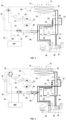
FIG. 1 is a schematic diagram of an electric vehicle thermal management loop provided by an embodiment 1 of the present invention; -
FIG. 2 is a schematic diagram of a passenger compartment temperature control pipe system provided by the embodiment 1 of the present invention,FIG. 2 is directly transformed from the passenger compartment temperature control pipe system inFIG. 1 , and its connection relationship is exactly the same as that of the passenger compartment temperature control pipe system inFIG. 1 ; -
FIG. 3 is a schematic diagram of an electric vehicle thermal management loop provided by an embodiment 2 of the present invention; -
FIG. 4 is a schematic diagram of an electric vehicle thermal management loop provided by an embodiment 3 of the present invention; -
FIG. 5 is a schematic diagram of the electric vehicle thermal management loop provided by an embodiment of the present invention; -
FIG. 6 is a schematic diagram of a first pipe system provided by an embodiment of the present invention; -
FIG. 7 is a schematic diagram of a second pipe system provided by an embodiment of the present invention; -
FIG. 8 is a schematic diagram of a third pipe system provided by an embodiment of the present invention; -
FIG. 9 is a schematic diagram of a vehicle air conditioning system provided by an embodiment of the present invention; -
FIG. 10 is a schematic diagram of a transformation state of the vehicle air conditioning system provided by an embodiment of the present invention, and connection relationships of components in the present diagram are completely consistent withFIG 9 . - The implementation modes of the present invention are described below through specific embodiments, and those skilled in the art can easily understand other advantages and effects of the present invention from contents disclosed in the description. It should be noted that the following embodiments and the features in the embodiments can be combined with each other without conflict.
- It should be noted that the diagrams provided in the following embodiments only illustrates the basic concept of the present invention in a schematic way, so the diagram only shows the components related to the present invention rather than number, shape, and size of components in actual implementation. Type, number, and proportion of each component may vary arbitrarily in its actual implementation, and the layout of the components may be more complex.
- As shown in
FIG. 1 , an electric vehicle thermal management loop comprises a driving motor cooling pipe system, a power battery temperature control pipe system, a passenger compartment temperature control pipe system, a first control pipe system, and a second control pipe system. - For details, please refer to
FIG. 1 , the driving motor cooling pipe system comprises anexpansion kettle 11, afirst water pump 12, a drivingmotor 13, and a low-temperature radiator 14 connected in sequence. It can be understood that the drivingmotor 13 in the present invention refers to a cooling water channel of the drivingmotor 13, not the power structure of the drivingmotor 13 itself. The power battery temperature control pipe system comprises asecond water pump 21, afirst PTC heater 22, abattery cooler 23, and apower battery 24 connected in sequence. It can be understood that thepower battery 24 of the present invention refers to a cooling channel of thepower battery 24, not the electrochemical structure of thepower battery 24 itself. The passenger compartment temperature control pipe system comprises anelectric compressor 41, anoutdoor heat exchanger 42, anevaporator 43, a gas-liquid separator 44, an in-vehicle condenser 45, aheat exchange pipe 46, and asecond PTC heater 47. Theheat exchange pipe 46 passes through thebattery cooler 23 to realize heat exchange with the power battery temperature control pipe system. Theevaporator 43, the in-vehicle condenser 45, and thesecond PTC heater 47 are all located in the air duct of the vehicle air conditioning system. The low-temperature radiator 14 and theoutdoor heat exchanger 42 are both located behind agrille 71 on a front face of the vehicle, and the low-temperature radiator 14 is located in front of theoutdoor heat exchanger 42, and a coolingfan 72 is disposed a rear side of theoutdoor heat exchanger 42. - For details, please refer to
FIG. 1 , the first control pipe system is located between the driving motor cooling pipe system and the power battery temperature control pipe system. The first control pipe system is configured to enable the driving motor cooling pipe system and the power battery temperature control pipe system to switch among following four states: - state 1, the driving motor cooling pipe system and the power battery temperature control pipe system forming independent closed loops respectively;
- state 2, the driving motor cooling pipe system and the power battery temperature control pipe system connected in series to a closed loop;
- state 3, the
expansion kettle 11, thefirst water pump 12, the drivingmotor 13, thesecond water pump 21, thebattery cooler 23, and thepower battery 24 connected in series to a closed loop; - state 4, the
expansion kettle 11, thefirst water pump 12, the drivingmotor 13, thesecond water pump 21, and thebattery cooler 23 connected in series in sequence to form a closed loop. - It can be understood, in a specific embodiment of the present invention, the above four states can be selectively set, for example, only state 1, state 2, and state 3 can be set.
- As shown in
FIG. 1 , as a preferred embodiment of the present invention, the first control pipe system comprises a six-way valve 31, which comprises: - a first port 1, connected to the low-
temperature radiator 14; - a second port 2, connected to one end of a
first branch pipe 32, and another end of thefirst branch pipe 32 connected to a water outlet end of the drivingmotor 13; - a third port 3, connected to the
expansion kettle 11; - a fourth port 4, connected to a water outlet end of the
power battery 24; - a fifth port 5, connected to one end of the
second branch pipe 33, and another end of thesecond branch pipe 33 connected to a pipe between thebattery cooler 23 and thepower battery 24; - a sixth port 6, connected to the
second water pump 21. - The six-
way valve 31 is configured to be able to switch among at least following four working stations: - station 1, the first port 1 communicated with the third port 3, and the fourth port 4 communicated with the sixth port 6;
- station 2, the first port 1 communicated with the sixth port 6, and the fourth port 4 communicated with the third port 3;
- station 3, the second port 2 communicated with the sixth port 6, and the fourth port 4 communicated with the third port 3;
- station 4, the second port 2 communicated with the sixth port 6, and the fifth port 5 communicated with the third port 3.
- It can be understood that the station 1, the station 2, the station 3, and the station 4 of the six-
way valve 31 respectively realize the state 1, the state 2, the state 3, and the state 4. - As shown in
FIG. 1 and FIG. 2 , the second control pipe system is configured to enable the passenger compartment temperature control pipe system to switch between the following two states: - state a, the
electric compressor 41, theoutdoor heat exchanger 42, theevaporator 43, and the gas-liquid separator 44 connected in series in sequence to form a closed loop, and theheat exchange pipe 46 connected in parallel with theevaporator 43; and - state b, the
electric compressor 41, the in-vehicle condenser 45, theoutdoor heat exchanger 42, and the gas-liquid separator 44 connected in series in sequence to form a closed loop, and theheat exchange pipe 46 connected in parallel with theoutdoor heat exchanger 42. - Refer to
FIG. 2 , specifically, the second control pipe system comprises: - a
main pipe system 400, connected with theelectric compressor 41, theoutdoor heat exchanger 42, theevaporator 43, and the gas-liquid separator 44 in sequence to form a closed loop; - a first
sub-pipe system 401, connected in parallel with theoutdoor heat exchanger 42, and the in-vehicle condenser 45 connected to the firstsub-pipe system 401; - a second
sub-pipe system 402 connected in parallel with theevaporator 43, and theheat exchange pipe 46 connected to the secondsub-pipe system 402; - a third
sub-pipe system 403 connected between theoutdoor heat exchanger 42 and the gas-liquid separator 44; - a first control valve assembly, used to control a liquid outlet end of the
electric compressor 41 to be connected to either theoutdoor heat exchanger 42 or the in-vehicle condenser 45; - a second control valve assembly, used to control communication with or disconnection of the third
sub-pipe system 403. - As shown in
FIG. 2 , it can be understood, when the firstsub-pipe system 401 and the thirdsub-pipe system 403 are disconnected, the passenger compartment temperature control pipe system is in a refrigeration state. When the firstsub-pipe system 401 is communicated with the thirdsub-pipe system 403, the passenger compartment temperature control pipe system is in a heating state. The communication with or disconnection of the secondsub-pipe system 402 is related to heat exchange between the passenger compartment temperature control pipe system and the power battery temperature control pipe system. When the secondsub-pipe system 402 is disconnected, there is no heat exchange between the passenger compartment temperature control pipe system and the power battery temperature control pipe system, while when the secondsub-pipe system 402 is communicated, there is heat exchange between the passenger compartment temperature control pipe system and the power battery temperature control pipe system. Effects of the heat exchange are mainly in two aspects. On one hand, thepower battery 24 is cooled simultaneously during a cooling process of the passenger compartment temperature control pipe system; and on the other hand, the power battery temperature control pipe system absorbs heat generated by the motor during a heating process of the passenger compartment temperature control pipe system, thereby improving the heating effect of the passenger compartment temperature control pipe system, realizing energy recovery and reducing heating energy consumption. - As shown in
FIG. 2 , as a preferred embodiment of the present invention, the first control valve assembly comprises: - a first two-
way solenoid valve 51, located on themain pipe 400 between anelectric compressor 41 and theoutdoor heat exchanger 42, and located at downstream of a connection node between a front end of the firstsub-pipe system 401 and themain pipe system 400; - a second two-
way solenoid valve 52, located on the firstsub-pipe system 401. - It can be understood that the two-way solenoid valves of the present invention are stop valves, the stop valve has two stations of conduction and disconnection. Those skilled in the art, in light of the present invention, may employ other similar structures to control communicated and disconnected the tubes, and such alternatives are within scope of the present invention.
- Please refer to
FIG. 1 and FIG. 2 , as a preferred embodiment of the present invention, the second control valve assembly comprises a third two-way solenoid valve 53 disposed on the thirdsub-pipe system 403. - Refer to
FIG. 1 and FIG. 2 , further, a firstelectronic expansion valve 54 is disposed on the firstsub-pipe system 401, and the firstelectronic expansion valve 54 is located at an outlet end of the in-vehicle condenser 45. - Refer to
FIG. 1 and FIG. 2 , a secondelectronic expansion valve 56 is disposed on the secondsub-pipe system 402, and the secondelectronic expansion valve 56 is located at an inlet end of theheat exchange pipe 46. - Refer to
FIG. 1 and FIG. 2 , a thirdelectronic expansion valve 55 is disposed at an inlet end of theevaporator 43. - It can be understood that the present invention can realize independent control of the in-
vehicle condenser 45, theevaporator 43, andheat exchange pipe 46 through the above electronic expansion valves, so as to finely control the pipe systems according to actual temperature control demands. - As shown in
FIG. 1 and FIG. 2 , themain pipe system 400 is provided with a one-way valve 57, which is located on themain pipe system 400 between the firstsub-pipe system 401 and the secondsub-pipe system 402. - As shown in
FIG. 1 , the following positions are provided with temperature sensors: an outlet of theelectric compressor 41, a surface of theoutdoor heat exchanger 42, a suction port of theelectric compressor 41, a surface of theevaporator 43, an inlet of the drivingmotor 13, and an inlet of thepower battery 24. - As shown in
FIG. 1 , an outlet of the in-vehicle condenser 45 and an outlet of theevaporator 43 are provided with pressure sensors and temperature sensors. - It can be understood that the above temperature sensors and pressure temperature sensors can be connected to a trip computer or an independent controller, so as to adjust operation status of the pipe systems in real time according to ambient temperature and pipe operation parameters.
- Based on the above electric vehicle thermal management loop, the present invention also provides a control method of the electric vehicle thermal management loop, comprises:
controlling the driving motor cooling pipe system and the power battery temperature control pipe system to form independent closed loops respectively, when both the passenger compartment and thepower battery 24 have cooling requirements; controlling theelectric compressor 41, theoutdoor heat exchanger 42, theevaporator 43, and the gas-liquid separator 44 to be connected in series in sequence to form a closed loop, and theheat exchange pipe 46 is connected in parallel with theevaporator 43; controlling thefirst PTC heater 22 to close; this working condition is often used in hot summer environment, for example, when the ambient temperature is greater than 30 ° C. - Controlling the driving motor cooling pipe system and the power battery temperature control pipe system in series to a closed loop; controlling the
electric compressor 41, theoutdoor heat exchanger 42, theevaporator 43, and the gas-liquid separator 44 to be connected in series in order to form a closed loop, and controlling theheat exchange pipe 46 to be disconnected from the passenger compartment temperature control pipe system; controlling thefirst PTC heater 22 to close; when the passenger compartment has a cooling demand, but thepower battery 24 has a low cooling demand, and outlet water temperature of the loop of the drivingmotor 13 is lower than that of thepower battery 24; this working condition is usually used in slightly hot environment in spring and autumn, for example, when the ambient temperature is in arange 20 °C -30°C. - Controlling the
expansion kettle 11, thefirst water pump 12, thedrive motor 13, thesecond water pump 21, thebattery cooler 23, and thepower battery 24 to form a closed loop in series; controlling disconnection of theheat exchange pipe 46 from the passenger compartment temperature control pipe system; controlling thefirst PTC heater 22 to close; when thepower battery 24 has a small load heating demand and outlet water temperature of the drivingmotor 13 is higher than the power motor loop; this working condition is often used in the slightly cold environment in spring and autumn, for example, when the ambient temperature is in a range of 10°C -20°C . - Controlling the cooling pipe system of the driving motor and the temperature control pipe system of the power battery to form independent closed loops respectively; controlling opening of the
first PTC heater 22; controlling theelectric compressor 41, thevehicle condenser 45, theoutdoor heat exchanger 42, and the gas-liquid separator 44 in series in sequence to form a closed loop; controlling disconnection of theheat exchange pipe 46 from the passenger compartment temperature control pipe system, when both the passenger compartment and thepower battery 24 have heating demands; this working condition is often used in cold winter environment, for example, when the ambient temperature is in a range of -30°C to 0°C. - Controlling the
expansion kettle 11, thefirst water pump 12, the drivingmotor 13, thesecond water pump 21, and thebattery cooler 23 to form a closed loop in series; controlling theelectric compressor 41, the in-vehicle condenser 45, theoutdoor heat exchanger 42, and the gas-liquid separator 44 in series in sequence to form a closed loop; theheat exchange tube 46 is controlled to be connected in parallel with theoutdoor heat exchanger 42, when only the passenger compartment needs heating. - When the ambient temperature is extremely low, such as below -20°C, the present invention can improve heating efficiency of the
power battery 24 and the passenger compartment through afirst PTC heater 22 and asecond PTC heater 47. - A difference between the present embodiment and the embodiment 1 is that only specific embodiments of the first control pipe system and the first control valve assembly are different.
- As shown in
FIG. 3 , in the present embodiment, the first control pipe system comprises a four-way valve 34, a first three-way valve 35, and a second three-way valve 37; - four ports of the four-
way valve 34 are respectively connected to the low-temperature radiator 14, theexpansion kettle 11, thepower battery 24, and thesecond water pump 21; - two ports of the first three-
way valve 35 are connected in series on the pipe between the drivingmotor 13 and the low-temperature radiator 14, the third port is connected to one end of athird branch pipe 36, and another end of thethird branch pipe 36 is connected to the pipe between the low-temperature radiator 14 and the four-way valve 34; - two ports of the second three-
way valve 37 are connected in series on the pipe between thebattery cooler 23 and thepower battery 24, the third port is connected to one end of the fourth branch pipe 28, and another end of the fourth branch pipe 28 is connected to the pipe between thepower battery 24 and the four-way valve 34. - As shown in
FIG. 3 , the first control valve assembly comprises a third three-way valve 58, which is located at a connection node between a front end of thefirst sub-pipe 401 and themain pipe 400. - It can be understood that under enlightenment of the embodiment 1 and the embodiment 2 of the present invention, those skilled in the art can also use other forms of valve structures to achieve switching between the above different states of the invention, and these alternatives also belong to scope of protection of the present invention.
- A difference between the present embodiment and embodiment 1 is that only the specific implementation methods of the first control valve assembly are different.
- As shown in
FIG. 4 , in the present embodiment, the first control valve assembly comprises a third three-way valve 58, which is located at a connection node between a front end of the firstsub pipe system 401 and themain pipe system 400. - It is understood that under the enlightenment of the embodiment 1 and the embodiment 3 of the present invention, those skilled in the art can also use other forms of valve structures to realize alternate control between the
outdoor heat exchanger 42 and the in-vehicle condenser 45 in the present invention, and these alternatives also belong to the scope of the present invention; - The present invention realizes a series parallel operation of the cooling loop of the driving
motor 13 and the cooling loop of thepower battery 24 of the electric vehicle, the low-temperature radiator 14 of the loop of thebypass driving motor 13, thebypass power battery 24, the thermal coupling of the water loop and the refrigerant loop, the bypass of the heat exchanger in the passenger compartment, the reversing of the cooling and heating conditions of theoutdoor heat exchanger 42, and effectively reduces energy consumption of the system and improves battery life on a premise of meeting cooling and heating demands . - As shown in
FIG. 5 , an electric vehicle thermal management loop comprises a first pipe system 10', a second pipe system 20', and a first reversing module. - As shown in
FIG. 5 and FIG. 6 , the first pipe system 10' comprises an expansion kettle 11', a first water pump 12', a driving motor 13', and a low-temperature radiator 14' which are connected in series. - As shown in
FIG. 5 andFIG. 7 , the second pipe system 20' comprises a second water pump 21', a power battery 22', and a battery cooler 23' connected in series. - As shown in
FIG. 5, FIG. 6 andFIG. 7 , the first reversing module is connected between the first pipe system 10' and the second pipe system 20'. The first reversing module is configured to enable the first pipe system 10' and the second pipe system 20' to switch among the following four stations: - station 1, the first pipe system 10' and the second pipe system 20' forming independent closed loops respectively;
- station 2, the expansion kettle 11', the first water pump 12', the driving motor 13', the low-temperature radiator 14', and the power battery 22' connected in series to form a closed loop;
- station 3, the expansion kettle 11', the first water pump 12', the driving motor 13', and the power battery 22' connected in series to form a closed loop;
- station 4, the expansion kettle 11', the first water pump 12', the driving motor 13', and the battery cooler 23' connected in series to form a closed loop.
- As shown in
FIG. 5 ,FIG. 7 , andFIG. 9 , the battery cooler 23' comprises a first flow channel 231' and a second flow channel 232'. The first flow channel 231' and the second flow channel 232' are independent with each other and can conduct heat exchange therebetween. The first flow channel 231' is connected in series to the second pipe system 20', and the second flow channel 232' is connected to the low-temperature pipe of the vehicle air conditioning system. - It can be understood that in the expression of the present invention, the driving motor 13' refers to the cooling water loop of the driving motor 13', not the power structure of the driving motor 13' itself. Similarly, the power battery 22' refers to the cooling water loop of the power battery 22', not the electrochemical structure of the power battery 22'.
- The present invention can selectively connect the power battery 22' to the air conditioning system or the driving motor 13'. When connected to the air conditioning system, the battery is cooled. When connected to the driving motor 13', on one hand, cooling liquid of the driving motor 13' can be used to cool the battery; on the other hand, residual heat of the driving motor 13' can be used to heat the battery and reduce system energy consumption. In addition, the present invention can directly conduct heat exchange between the cooling liquid of the driving motor 13' and the air conditioning system, and can absorb residual heat of the driving motor 13' when the air conditioning system is in heating, thereby reducing the system energy consumption while ensuring the heating effect.
- As shown in
FIG. 5 andFIG. 9 , it also comprises a third pipe system 30'. The third pipe system 30' comprises a third water pump 31', a PTC heater 32', and a heating core 33' connected in series. The heating core 33' is located in an air duct of the vehicle air conditioning system, and the heating core 33' is connected in parallel to both ends of the power battery 22'; the third pipe 30' is provided with a second reversing module, and the second reversing module is configured to enable the third pipe system 30' to switch among following three stations: - station a, the third water pump 31', the PTC heater 32', and heater core 33' connected in series to a closed loop;
- station b, the third water pump 31', the PTC heater 32', and the power battery 22' connected in series to a closed loop;
- station c, the third water pump 31', the PTC heater 32', and the heater core 33' connected in series to form a closed loop, while the third water pump 31', the PTC heater 32' and the power battery 22' connected in series to form a closed loop.
- As shown in
FIG. 1 andFIG. 4 , the second reversing module in the present invention can be a three-way proportional valve 301', for example. It can be foreseen that the present invention can also use two stop valves to replace the three-way proportional valve 301'. - When the ambient temperature is low, such as lower than -20°C, the present invention can also auxiliarily heat the power battery 22' and the passenger compartment through the PTC heater 32', so as to ensure that the power battery 22' works at a suitable temperature and improve electric energy conversion rate.
- As shown in
FIG. 5 ,FIG. 9, and FIG. 10 , the third pipe system 30' is connected in series with a water-cooled condenser 34'. The water-cooled condenser 34' comprises a flow channel a341' and a flow channel b342'. The flow channel a341' and the flow channel b342' are independent with each other and can conduct heat exchange therebetween. The flow channel a341' is connected in series with the third pipe system 30', and the flow channel b 342' is connected to high-temperature pipe of the vehicle air conditioning system. The present invention can realize the heat exchange between the third pipe system 30' and the air conditioning system. When heating demand of the passenger compartment is small, the air conditioning system can be used to heat the passenger compartment. At the same time, the air conditioning system can recover residual heat of the driving motor 13', which reduces the system energy consumption while ensuring heating effect of the passenger compartment. - As shown in
FIG. 9 and FIG. 10 , the vehicle air conditioning system comprises an electric compressor 41', an outdoor heat exchanger 42', an evaporator 43', and a gas-liquid separator 44' connected to each other; it also comprises a third reversing module, which is configured to enable the vehicle air conditioning system to switch between the following two stations: - station I, the electric compressor 41', the outdoor heat exchanger 42', the evaporator 43', and the gas-liquid separator 44' connected in series to form a closed loop, and the second flow channel 232' connected in parallel with the evaporator 43';
- station II, the electric compressor 41', the flow channel b342', the outdoor heat exchanger 42', and the gas-liquid separator 44' connected in series to form a closed loop, and the second flow channel 232' connected in parallel with the outdoor heat exchanger 42';
- the evaporator 43' is located in air duct of the vehicle air conditioning system.
- It can be understood that the above station I corresponds to the cooling state of the air conditioner, while the above station II corresponds to the heating state of the air conditioner.
- As shown in
FIG. 1, FIG. 2 , andFIG. 3 , the first reversing module is configured to enable the first pipe system 10' and the second pipe system 20' to be switched to station 5, the station 5 is: the expansion kettle 11', the first water pump 12', and the driving motor 13' form a closed loop independently; the second water pump 21' and the power battery 22' form a closed loop independently. It can be understood that when the power battery 22' has no heating and cooling demands and the ambient temperature is slightly low, the first reversing module can be adjusted to the station 5. At this status, the first pipe system 10' can conduct cyclic heat storage. When the air conditioning system needs heating, the first reversing module can be switched to the station 4, so as to transfer the heat in the first pipe system 10' to the air conditioning system, further improving residual heat utilization rate of the driving motor 13', and reducing the system energy consumption. - As shown in
FIG. 9 and FIG. 10 , the electric compressor 41', the outdoor heat exchanger 42', the evaporator 43' and the gas-liquid separator 44' are connected in series on a main pipe system 40', and the main pipe system 40' is a closed loop. One end of the flow channel b342' is connected with the main pipe system 40' between the electric compressor 41' and the outdoor heat exchanger 42', and another end of the flow channel b342' is connected to the main pipe system 40' between the outdoor heat exchanger 42' and the evaporator 43'. Both ends of the second flow channel 232' are respectively connected to both ends of the evaporator 43'. It can be understood that when the vehicle is charged, the power battery 22' has a heating demand while the passenger compartment has no heating demand. At this status, the power battery 22' can be communicated with the third pipe system 30', and the heating core 33' can be disconnected from the third pipe system 30'. The third pipe system 30' can be heated either by the air conditioning system or the PTC heater 32' for heating. - As shown in
FIG. 9 and FIG. 10 , the third reversing module comprises a first stop valve 401', a second stop valve 402', a return branch pipe 404', and a third stop valve 403'. - As shown in
FIG. 10 , the first stop valve 401' is located on the main pipe system 40' between the electric compressor 41' and the outdoor heat exchanger 42'; - as shown in
FIG. 10 , the second stop valve 402' is located on the flow channel b342'; - as shown in
FIG. 10 , one end of the return branch pipe 404' is connected to the main pipe system 40' between the first stop valve 401' and the outdoor heat exchanger 42', and another end is connected to the gas-liquid separator 44'; - as shown in
FIG. 10 , the third stop valve 403' is located on the return branch pipe 404'. - Please refer to
FIG. 9 and FIG. 10 , the vehicle air conditioning system further comprises a first electronic expansion valve 405', and the first electronic expansion valve 405' is located on a pipe leading from the flow channel b to the outdoor heat exchanger 42' in the station II. Both ends of the first electronic expansion valve 405' are connected in parallel with the first one-way valve 408'. A second one-way valve 409' is connected in series on the return branch pipe 404'. A second electronic expansion valve 406' is connected in series on the second flow channel 232'. The vehicle air conditioning system further comprises a third electronic expansion valve 407', and the third electronic expansion valve 407' is located on a pipe leading from the outdoor heat exchanger 42' to the evaporator 43' under the status of station I. - Please refer to
FIG. 5, FIG. 6 , andFIG. 7 , as a preferred embodiment of the present invention, the first reversing module comprises a six-way valve 101', a first branch pipe 102', and a second branch pipe 103'; one end of the first branch pipe 102' is connected to the pipe between the driving motor 13' and the low-temperature radiator 14', and another end is connected to the six-way valve 101'; one end of the second branch pipe 103' is connected to the pipe between the power battery 22' and the battery cooler 23', and another end is connected to the six-way valve 101'. - Please refer to
FIG. 5 , the six-way valve 101' has a first port 1', a second port 2', a third port 3', a fourth port 4', a fifth port 5', and a sixth port 6'. - The first port 1' is connected to the battery cooler 23'; the second port 2' is connected to the second branch pipe 103'; the third port 3' is connected to the second water pump 21'; the fourth port 4' is connected to the expansion kettle 11'; the fifth port 5' is connected to the first branch pipe 102'; and the sixth port 6' is connected to the low-temperature radiator 14'.
- The six-way valve 101' is configured as follows: the first port 1' is able to be communicated with or disconnected from any one of the third port 3' and the fourth port 4'; the second port 2' is able to be communicated with or disconnected from any one of the third port 3' and the fourth port 4'; the fifth port 5' is able to be communicated with or disconnected from any one of the third port 3' and the fourth port 4'; and the sixth port 6' is able to be communicated with or disconnected from any one of the third port 3' and the fourth port 4'.
- It can be understood that in addition to the six-way valve 101', the present invention can also use a combination of multiple stop valves to achieve the above-mentioned control process.
- Please refer to
FIG. 5 , the low-temperature radiator 14' and the outdoor heat exchanger 42' are located behind a grille 50' on a front face of the vehicle, and a cooling fan 60' is disposed behind the low-temperature radiator 14' and/or outdoor heat exchanger 42'. - Please refer to
FIG. 5 and FIG. 6 , the first pipe system 10' also passes through a wireless charging module 15', an intelligent driving module 16', and a vehicle charger 17' to cool these components. - Based on the thermal management loop, the present invention further provides a pure electric vehicle, which comprises: a passenger compartment; a power system; and a thermal management loop, and the thermal management loop comprises a first pipe system 10', a second pipe system 20', and a first reversing module.
- The first pipe system 10' comprises an expansion kettle 11', a first water pump 12', a driving motor 13', and a low-temperature radiator 14' connected in series; the second pipe system 20' comprises a second water pump 21', a power battery 22', and a battery cooler 23' connected in series; and the first reversing module is connected between the first pipe system 10' and the second pipe system 20', and the first reversing module is configured to enable the first pipe system 10' and the second pipe system 20' to switch among the following four stations:
- station 1, the first pipe system 10' and the second pipe system 20' forming independent closed loop respectively;
- station 2, the expansion kettle 11', the first water pump 12', the driving motor 13', the low-temperature radiator 14', and the power battery 22' connected in series to form a closed loop;
- station 3, the expansion kettle 11', the first water pump 12', the driving motor 13', and the power battery 22' connected in series to form a closed loop;
- station 4, the expansion kettle 11', the first water pump 12', the driving motor 13', and the battery cooler 23' connected in series to form a closed loop;
- wherein the battery cooler 23' comprises a first flow channel 231' and a second flow channel 232', the first flow channel 231' and the second flow channel 232' are independent of each other and can conduct heat exchange therebetween, the first flow channel 231' is connected in series to the second pipe system 20', and the second flow channel 232' is connected to a low-temperature pipe of the vehicle air conditioning system.
- Based on the thermal management loop, the present invention also provides a control method of an electric vehicle thermal management loop, specifically:
under a high temperature working condition in summer, for example, when the ambient temperature is greater than 30°C, both the passenger compartment and the power battery 22' have cooling demands, the electric compressor 41', the cooling fan 60', and an active grid are all turned on, a refrigerant in high temperature and high pressure state enters the outdoor heat exchanger 42' through the first stop valve 401' and becomes liquid after cooling; it reaches the second electronic expansion valve 406' and the third electronic expansion valve 407' respectively through the first one-way valve 408'; the refrigerant throttled by the second electronic expansion valve 406' enters the battery cooler 23' to cool a power battery 22' loop; the refrigerant throttled by the third electronic expansion valve 407' enters the evaporator 43' to cool the passenger compartment. Under this working condition, since the second stop valve 402' is turned off, the refrigerant will not enter the water-cooled condenser 34' and the third water pump 31' will not work, which can reduce heat load of cooling in the vehicle; under this working condition, the six-way valve 101' on a water way side is in an initial state, the second water pump 21' drives coolant to enter the power battery 22', and then enters the battery cooler 23' for cooling; the cooled coolant returns to the second water pump 21' through the first port 1 and the third port 3 of the six-way valve 101' to cool the battery's internal battery cell. Under this working condition, the coolant of the loop of the driving motor 13' comes out of the first water pump 12' and is divided into two paths to front and rear driving motors 13' and other components requiring liquid cooling, and then combined into one path to enter the low-temperature radiator 14'; the high temperature coolant is cooled in the low-temperature radiator 14' and then returns to the expansion kettle 11' through the sixth port 6' and the fourth port 4' of the six-way valve 101', and then enters the first water pump 12' again. - When ambient temperature is relatively high in spring and autumn working conditions, for example, when the ambient temperature is in the range of 20°C- 30°C, when the passenger compartment has cooling demand, the second electronic expansion valve 406' is turned off, and a working mode of other refrigerant loop components is the same as that in the summer working condition. When the cooling demand of the power battery 22' is not high and an outlet water temperature of the loop of the driving motor 13' is lower than that of the power battery 22', a working mode of the six-way valve 101' is that, the sixth port 6' is communicated with the third port 3', the second port 2' is communicated with the fourth port 4', the driving motor 13' and the loop of the power battery 22' operate in series, and the power battery 22' dissipates heat through the low-temperature radiator 14'. When the cooling demand of the power battery 22' is high, the parallel operation mode at the waterway side is the same as that in the summer cooling working condition. When the ambient temperature under spring and autumn working conditions is relatively low, for example, when the ambient temperature is in the range of 10°C- 20°C, when the power battery 22' has a small load heating demand and the outlet water temperature of the driving motor 13' is higher than that of the power motor loop, the working mode of the six-way valve 101' is that, the fifth port 5' is communicated with the third port 3', the second port 2' is communicated with the fourth port 4', bypass the low-temperature radiator 14'; and the coolant enters the second water pump 21' through the fifth port 5' and the third port 3' of the six-way valve 101' after coming out of the front and rear driving motors 13', and then enters into the power battery 22'. After coming out of the power battery 22', the coolant enters the expansion kettle 11' through the second port 2' and the fourth port 4' of the six-way valve 101', and then returns to the first water pump 12' again.
- Under low-temperature working conditions in winter, for example, when the ambient temperature is in the range of -30°C- 0°C, when both the passenger compartment and the power battery 22' have heating demands, the electric compressor 41', the cooling fan 60', and the active grid are all turned on. The refrigerant in high temperature and high pressure state enters the water-cooled condenser 34' through the second stop valve 402' to heat the coolant in a heating loop. The coolant, coming out of the water-cooled condenser 34', is compensated and heated by the PTC heater 32', and is divided into two paths through the three-way proportional valve 301', and two-way flow is adjusted proportionally according to the heating demands of the passenger compartment and the power battery 22'. The high temperature coolant of the loop to the passenger compartment will heat air in the passenger compartment through the heater core 33', and then returns to the water-cooled condenser 34' through the third water pump 31'. The high temperature coolant of the loop to the power battery 22' enters the power battery 22' through the second water pump 21' to heat the battery, and returns to the third water pump 31' and then to the water-cooled condenser 34' again. Refrigerant at the refrigerant side comes out of the water-cooled condenser 34', and then is throttled by the first electronic expansion valve 405', and enters the outdoor heat exchanger 42' to absorb external environment heat, then enters the gas-liquid separator 44' through the third stop valve 403' and the second one-way valve 409', and returns to the electric compressor 41'. The fifth port 5' of the six-way valve 101' is connected to the fourth port 4' of the six-way valve 101', the second port 2' is connected to the third port 3', and the loop of the driving motor 13' bypasses the low-temperature radiator 14' for independent operation to store heat.
- For heating in the passenger compartment with remaining heat recovery, when only the passenger compartment has heating demands, the refrigerant comes out of the water-cooled condenser 34' and arrives at the first electronic expansion valve 405' and the second electronic expansion valve 406' respectively. The refrigerant passing through the first electronic expansion valve 405' enters the outdoor heat exchanger 42' to absorb ambient heat, and then enters the gas-liquid separator 44' through the third stop valve 403' and the second one-way valve 409', and returns to the electric compressor 41'. The refrigerant passing through the second electronic expansion valve 406' enters the battery cooler 23' to absorb heat at a coolant side, and then returns to the electric compressor 41' again after passing through the gas-liquid separator 44'. A state of the six-way valve 101' on a waterway side is that the fifth port 5' is communicated with the first port 1', the second port 2' is communicated with the fourth port 4'. After coming out of the battery cooler 23', the coolant enters the expansion kettle 11' through the second port 2' and the fourth port 4' of the six-way valve 101', and then flows through the front and rear driving motors 13' respectively through the first water pump 12' in two paths, and then it returns to the battery cooler 23' again through the fifth port 5' and the first port 1 'of the six-way valve 101'.
- The present invention can heat the coolant in the heating loop through the water-cooled condenser 34' to realize heating of the power battery 22' under a fast charging condition of a low-temperature battery, that is, when only the power battery 22' has the heating demand.
- The present invention realizes the series and parallel operations of the cooling loop of the driving motor 13' and the cooling loop of the power battery 22' of the electric vehicle, the low-temperature radiator 14' of the loop of the bypass driving motor 13', the bypass power battery 22', the thermal coupling of the water loop and the cooling loop, the bypass of the passenger compartment and heat exchanger, the reversing of the cooling and heating conditions of the outdoor heat exchanger, the use of heat pumps for heating the power battery 22' and other functions. While ensuring the temperature control efficiency, the present invention reduces the energy consumption of the systems and improves the vehicle endurance.
- The above-mentioned embodiments only exemplify the principle and efficacy of the present invention, and are not used to limit the present invention.
- In the description, many specific details, such as examples of components and/or methods, are provided to provide a complete understanding of embodiments of the invention. However, those skilled in the art will recognize that embodiments of the present invention can be practiced without one or more specific details or through other devices, systems, assemblies, methods, components, materials, parts, and the like. In other cases, well-known structures, materials, or operations are not specifically shown or described in detail to avoid blurring aspects of embodiments of the present invention.
- The reference to "one embodiment", "embodiment" or "specific embodiment" in the entire specification means that the specific features, structures or characteristics described in combination with the embodiments are included in at least one embodiment of the invention, and not necessarily in all embodiments. Therefore, the expressions "in one embodiment", "in an embodiment" or "in a specific embodiment" in different places throughout the specification do not necessarily refer to the same embodiment. In addition, specific features, structures, or characteristics of any particular embodiment of the present invention may be combined with one or more other embodiments in any suitable manner.
- It should also be understood that one or more of the elements shown in the drawings may also be implemented in a more separate or more integrated manner, or even removed because they are not operable in some cases, or provided because they can be useful according to a particular application.
- In addition, unless otherwise expressly indicated, any arrow in the drawings should be considered as an example only, not a limitation. In addition, unless otherwise specified, the term "or" used here is generally intended to mean "and/or". When the term is foreseen because it is unclear to provide separation or combination capability, the combination of components or steps will also be deemed to have been specified.
- As used here and throughout the following claims, "one", and "the" include plural references unless otherwise specified. Similarly, as used in the description here and throughout the following claims, unless otherwise specified, "in" means "in" and "on".
- The above description of the embodiments of the present invention (comprising the content described in the abstract of the specification) is not intended to enumerate in detail or limit the invention to the precise form disclosed here.
- The system and method have been described here in general to facilitate understanding of the details of the present invention. In addition, various specific details have been given to provide a general understanding of embodiments of the present invention. However, those skilled in the relevant field will realize that embodiments of the invention can be practiced without one or more specific details, or with other devices, systems, accessories, methods, components, materials, parts, etc. In other cases, well-known structures, materials, and/or operations are not particularly shown or described in detail to avoid confusion with various aspects of embodiments of the invention.
- The present invention is not intended to limit the specific terms used in the following claims and/or the specific embodiments disclosed as the best way to implement the present invention, but the present invention will include any and all embodiments and equivalents falling within the scope of the appended claims. Therefore, the scope of the present invention will be determined only by the appended claims.
Claims (15)
- An electric vehicle thermal management loop, characterized in that, it comprises:a driving motor cooling pipe system, comprising an expansion kettle (11), a first water pump (12), a driving motor (13), and a low-temperature radiator (14) connected in sequence;a power battery temperature control pipe system, comprising a second water pump (21), a battery cooler (23), and a power battery (24) connected in sequence;a first control pipe system, located between the driving motor cooling pipe system and the power battery temperature control pipe system, the first control pipe system configured to enable the driving motor cooling pipe system and the power battery temperature control pipe system to switch among the following three states:state 1: the driving motor cooling pipe system and the power battery temperature control pipe system forming independent closed loops respectively;state 2: the driving motor cooling pipe system and the power battery temperature control pipe system connected in series to a closed loop; andstate 3: the expansion kettle (11), the first water pump (12), the driving motor (13), the second water pump (21), the battery cooler (23), and the power battery (24) connected in series to a closed loop.
- The electric vehicle thermal management loop as claimed in claim 1, characterized in that, it further comprises a passenger compartment temperature control pipe system, and the passenger compartment temperature control pipe system comprising an electric compressor (41), an outdoor heat exchanger (42), an evaporator (43), a gas-liquid separator (44), an in-vehicle condenser (45), and a heat exchange pipe (46); and
a second control pipe system, configured to enable the passenger compartment temperature control pipe system to switch between the following two states:state a, the electric compressor (41), the outdoor heat exchanger (42), the evaporator (43), and the gas-liquid separator (44) connected in series in sequence to form a closed loop, and the heat exchange pipe (46) connected in parallel with the evaporator (43); andstate b, the electric compressor (41), the in-vehicle condenser (45), the outdoor heat exchanger (42), and the gas-liquid separator (44) connected in series in sequence to form a closed loop, and the heat exchange pipe (46) connected in parallel with the outdoor heat exchanger (42); andthe heat exchange pipe (46) passing through the battery cooler (23) to realize heat exchange with the power battery temperature control pipe system. - The electric vehicle thermal management loop as claimed in claim 2, characterized in that, the first control pipe system is configured to enable the motor cooling pipe system and the power battery temperature control pipe system to be switched to state 4;state 4: the expansion kettle (11), the first water pump (12), the driving motor (13), the second water pump (21), and the battery cooler (23) are sequentially connected in series to a closed loop;preferably the first control pipe system comprises a six-way valve (31), and the six-way valve (31) comprises:a first port (1), connected to the low-temperature radiator (14);a second port (2), connected to one end of a first branch pipe (32), and another end of the first branch pipe (32) connected to a water outlet end of the driving motor (13);a third port (3), connected to the expansion kettle (11);a fourth port (4), connected to a water outlet end of the power battery (24);a fifth port (5), connected to one end of a second branch pipe (33), and another end of the second branch pipe (33) connected to a pipe between the battery cooler (23) and the power battery (24); anda sixth port (6), connected to the second water pump (21);preferably, the six-way valve (31) is configured to switch among the following stations:station 1, the first port (1) communicated with the third port (3), and the fourth port (4) communicated with the sixth port (6);station 2, the first port (1) communicated with the sixth port (6), and the fourth port (4) communicated with the third port (3);station 3, the second port (2) communicated with the sixth port (6), and the fourth port (4) communicated with the third port (3); andstation 4, the second port (2) communicated with the sixth port (6), and the fifth port (5) communicated with the third port (3).
- The electric vehicle thermal management loop as claimed in claim 3, characterized in that, the first control pipe system comprises a four-way valve (34), a first three-way valve (35), and a second three-way valve (37);four ports of the four-way valve (34) are respectively connected to the low-temperature radiator (14), the expansion kettle (11), the power battery (24), and the second water pump (21);two ports of the first three-way valve (35) are connected in series on the pipe between the driving motor (13) and the low-temperature radiator (14), the third port is connected to one end of a third branch pipe (36), and another end of the third branch pipe (36) is connected to a pipe between the low-temperature radiator (14) and the four-way valve (34); andtwo ports of the second three-way valve (37) are connected in series on the pipe between the battery cooler (23) and the power battery (24), the third port is connected to one end of a fourth branch pipe (28), and another end of the fourth branch pipe (28) is connected to a pipe between the power battery (24) and the four-way valve (34).
- The electric vehicle thermal management loop as claimed in claim 3 or 4, characterized in that, the second control pipe system comprises:a main pipe system (400), connected to the electric compressor (41), the outdoor heat exchanger (42), the evaporator (43), and the gas-liquid separator (44) in sequence to form a closed loop;a first sub-pipe system (401), connected in parallel with the outdoor heat exchanger (42), and the in-vehicle condense (45) connected to the first sub-pipe system (401);a second sub-pipe system (402), connected in parallel with the evaporator (43), and the heat exchange pipe (46) connected to the second sub-pipe system (402);a third sub-pipe system (403), connected between the outdoor heat exchanger (42) and the gas-liquid separator (44);a first control valve assembly, used to control a liquid outlet end of the electric compressor (41) to be connected to either the outdoor heat exchanger (42) or the in-vehicle condenser (45); anda second control valve assembly, used to control communication with or disconnection of the third sub-pipe system (403).
- The electric vehicle thermal management loop as claimed in claim 5, characterized in that, the first sub-pipe system (401) is provided with a first electronic expansion valve (54), and the first electronic expansion valve (54) is located at a liquid outlet end of the in-vehicle condenser (45); the second sub-pipe system (402) is provided with a second electronic expansion valve (56), and the second electronic expansion valve (56) is located at a liquid inlet end of the heat exchange pipe (46); a liquid inlet end of the evaporator (43) is provided with a third electronic expansion valve (55); the main pipe system (400) is provided with a one-way valve (57), and the one-way valve (57) is located on the main pipe system (400) between the first sub-pipe system (401) and the second sub-pipe system (402); a pressure and temperature sensor is disposed on an outlet of the in-vehicle condenser (45) and/or an outlet of the evaporator (43).
- The electric vehicle thermal management loop as claimed in any of claims 2 to 6, characterized in that, the power battery temperature control pipe system is provided with a first PTC heater (22), and the first PTC heater (22) is located between the second water pump (21) and the battery cooler (23); the evaporator (43) and the in-vehicle condenser (45) are both located in an air duct of a vehicle air conditioning system; and a second PTC heater (47) is disposed in the air duct of the vehicle air conditioning system.
- A control method for an electric vehicle thermal management loop, characterized in that the electric vehicle thermal management loop comprises a driving motor cooling pipe system, a power battery temperature control pipe system, and a passenger compartment temperature control pipe system; the driving motor cooling pipe system comprises an expansion kettle (11), a first water pump (12), a driving motor (13), and a low-temperature radiator (14) connected in sequence; the power battery temperature control pipe system comprises a second water pump (21), a first PTC heater (22), a battery cooler (23), and a power battery (24) connected in sequence; the passenger compartment temperature control pipe system comprises an electric compressor (41), an outdoor heat exchanger (42), an evaporator (43), a gas-liquid separator (44), an in-vehicle condenser (45), a heat exchange pipe (46), and a second PTC heater (47); the heat exchange pipe (46) passes through the battery cooler (23) to realize heat exchange with the power battery temperature control pipe system; and
the control method comprises:controlling the driving motor cooling pipe system and the power battery temperature control pipe system to form independent closed loops respectively, when both the passenger compartment and the power battery have cooling demands; controlling the electric compressor (41), the outdoor heat exchanger (42), the evaporator (43), and the gas-liquid separator (44) to be connected in series in sequence to form a closed loop, and the heat exchange pipe (46) connected in parallel with the evaporator (43); and controlling the first PTC heater (22) to turn off;controlling the driving motor cooling pipe system and the power battery temperature control pipe system integrally to form a closed loop in series, when the passenger compartment has a cooling demand, the power battery cooling demand is not high, and outlet water temperature of the driving motor loop is lower than power battery water temperature; controlling the electric compressor (41), the outdoor heat exchanger (42), the evaporator (43), and the gas-liquid separator (44) to be connected in series in sequence to form a closed loop, and controlling the heat exchange pipe (46) to be disconnected from the temperature control pipe system in the passenger compartment; and controlling the first PTC heater (22) to turn off;controlling the expansion kettle (11), the first water pump (12), the driving motor (13), the second water pump (21), the battery cooler (23), and the power battery (24) to form a closed loop in series, when the power battery (24) has a small load heating demand and the outlet water temperature of the driving motor (13) is higher than that of the power motor loop; controlling the heat exchange pipe (46) disconnected from the passenger compartment temperature control pipe system; and controlling the first PTC heater (22) to turn off;controlling the driving motor cooling pipe system and the power battery temperature control pipe system to form independent closed loops respectively, when both the passenger compartment and the power battery (24) have heating demands; controlling the first PTC heater (22) to turn on; controlling the electric compressor (41), the in-vehicle condenser (45), the outdoor heat exchanger (42), and the gas-liquid separator (44) to be connected in series in sequence to form a closed loop; and controlling the heat exchange pipe (46) disconnected from the passenger compartment temperature control pipe system; andcontrolling the expansion kettle (11), the first water pump (12), the driving motor (13), the second water pump (21), and the battery cooler (23) to be connected in series in sequence to form a closed loop, when only the passenger compartment has heating demand; controlling the electric compressor (41), the in-vehicle condenser (45), the outdoor heat exchanger (42), and the gas-liquid separator (44) to be connected in series in sequence to form a closed loop; and controlling the heat exchange pipe (46) connected in parallel with the outdoor heat exchanger (42). - A pure electric vehicle, characterized in that, it comprises:a passenger compartment;a power system; anda thermal management loop, the thermal management loop comprising:a first pipe system (10'), comprising an expansion kettle (11'), a first water pump (12'), a driving motor (13'), and a low-temperature radiator (14') connected in series;a second pipe system (20'), comprising a second water pump (21'), a power battery (22'), and a battery cooler (23') connected in series;a first reversing module, connected between the first pipe system (10') and the second pipe system (20'), and the first reversing module configured to enable the first pipe system (10') and the second pipe system (20') to switch among the following four stations:station 1, the first pipe system (10') and the second pipe system (20') forming independent closed loops respectively;station 2, the expansion kettle (11'), the first water pump (12'), the driving motor (13'), the low-temperature radiator (14'), and the power battery (22') connected in series to form a closed loop;station 3, the expansion kettle (11'), the first water pump (12'), the driving motor (13'), and the power battery (22') connected in series to form a closed loop;station 4, the expansion kettle (11'), the first water pump (12'), the driving motor (13'), and the battery cooler (23') connected in series to form a closed loop;wherein the battery cooler (23') comprises a first flow channel (231') and a second flow channel (232'), the first flow channel (231') and the second flow channel (232') are independent of each other and are able to conduct heat exchange therebetween, the first flow channel (231') is connected in series to the second pipe system, and the second flow channel (232') is connected to a low-temperature pipe of a vehicle air conditioning system.
- The pure electric vehicle as claimed in claim 9, characterized in that, the electric vehicle thermal management loop further comprises a third pipe system (30'), and the third pipe system (30') comprises a third water pump (31'), a PTC heater (32'), and a heater core (33') connected in series, the heater core (33') is located in an air duct of a vehicle air conditioning system, and the heater core (33') is connected in parallel with both ends of the power battery (22'); the third pipe system (30') is provided with a second reversing module, and the second reversing module is configured to enable the third pipe system (30') to switch among the following three stations:station a, the third water pump (31'), the PTC heater (32'), and the heater core (33') connected in series to form a closed loop;station b, the third water pump (31'), the PTC heater (32'), and power battery (22') connected in series to form a closed loop;station c, the third water pump (31'), the PTC heater (32'), and the heater core (33') connected in series to form a closed loop, while the third water pump (31'), the PTC heater (32'), and the power battery (22') connected in series to form a closed loop.
- The pure electric vehicle as claimed in claim 10, characterized in that, the third pipe system (30') is connected in series with a water-cooled condenser (34'), the water-cooled condenser (34') comprises a flow channel a (341') and a flow channel b (342'), the flow channel a (341') and the flow channel b (342') are independent from each other and are able to conduct heat exchange therebetween, the flow channel a (341') is connected in series with the third-pipe system (30'), and the flow channel b (342') is connected to a high-temperature pipe of the vehicle air conditioning system; the vehicle air conditioning system comprises an electric compressor (41'), an outdoor heat exchanger (42'), an evaporator (43'), and a gas-liquid separator (44') connected to each other; the vehicle air conditioning system further comprises a third reversing module configured to enable the vehicle air conditioning system to switch between the following two stations:station I, the electric compressor (41'), the outdoor heat exchanger (42'), the evaporator (43'), and the gas-liquid separator (44') connected in series to form a closed loop, and the second flow channel (232') connected in parallel with the evaporator (43');station II, the electric compressor (41'), the flow channel b (342'), the outdoor heat exchanger (42') and the gas-liquid separator (44') connected in series to form a closed loop, and the second flow channel (232') connected in parallel with the outdoor heat exchanger (42'); andthe evaporator (43') located in the air duct of the vehicle air conditioning system.
- The pure electric vehicle as claimed in any of claims 9 to 11, characterized in that, the first reversing module is configured to enable the first pipe system (10') and the second pipe system (20') to be switched to station 5, and the station 5 is that: the expansion kettle (11'), the first water pump (12'), and the driving motor (13') form a closed loop independently; and the second water pump (21') and the power battery (22') form a closed loop independently.
- The pure electric vehicle as claimed in claim 11 or 12, characterized in that, the electric compressor (41'), the outdoor heat exchanger (42'), the evaporator (43'), and the gas-liquid separator (44') are connected in series on a main pipe system (40'), and the main pipe system (40') is a closed loop; one end of the flow channel b (342') is connected to one main pipe system (40') between the electric compressor (41') and the outdoor heat exchanger (42'), and another end of the flow channel b (342') is connected to the main pipe system (40') between the outdoor heat exchanger (42') and the evaporator (43'); and both ends of the second flow channel (232') are respectively connected to both ends of the evaporator (43'); the third reversing module comprises:a first stop valve (401'), located on the main pipe system (40') between the electric compressor (41') and the outdoor heat exchanger (42');a second stop valve (402'), located on the flow channel b (342');a return branch pipe (404'), one end of the return branch pipe connected to the main pipe system (40') between the first stop valve (401') and the outdoor heat exchanger (42'), and another end connected to the gas-liquid separator (44'); anda third stop valve (403'), located on the return branch pipe (404').
- The pure electric vehicle as claimed in claim 13, characterized in that, the vehicle air conditioning system further comprises a first electronic expansion valve (405') located on a pipe leading from the flow channel b (342') to the outdoor heat exchanger (42') in the station II;both ends of the first electronic expansion valve (405') are connected in parallel with a first one-way valve (408');a second one-way valve (409') is connected in series on the return branch pipe (404');a second electronic expansion valve (406') is connected in series on the second flow channel (232');the vehicle air conditioning system also comprises a third electronic expansion valve (407'), and the third electronic expansion valve (407') is located on a pipe leading from the outdoor heat exchanger (42') to the evaporator (43') under the status of station I.
- The pure electric vehicle as claimed in any of claims 9 to 14, characterized in that, the first reversing module comprises a six-way valve (101'), a first branch pipe (102'), and a second branch pipe (103');one end of the first branch pipe (102') is connected to the pipe between the driving motor (13') and the low-temperature radiator (14'), and another end is connected to the six-way valve (101');one end of the second branch pipe (103') is connected to the pipe between the power battery (22') and the battery cooler (23'), and another end is connected to the six-way valve (101');the six-way valve (101') has:a first port (1'), connected to the battery cooler (23');a second port (2'), connected to the second branch pipe (103');a third port (3'), connected to the second water pump (21');a fourth port (4'), connected to the expansion kettle (11');a fifth port (5'), connected to the first branch pipe (102');a sixth port (6'), connected to the low-temperature radiator (14');the six-way valve (101') is configured as follows:the first port (1') is able to be communicated with or disconnected from any one of the third port (3') and the fourth port (4');the second port (2') is able to be communicated with or disconnected from any one of the third port (3') and the fourth port (4');the fifth port (5') is able to be communicated with or disconnected from any one of the third port (3') and the fourth port (4'); andthe sixth port (6') is able to be communicated with or disconnected from any one of the third port (3') and the fourth port (4').
Applications Claiming Priority (1)
| Application Number | Priority Date | Filing Date | Title |
|---|---|---|---|
| CN202111519837.3A CN114056052B (en) | 2021-12-14 | 2021-12-14 | An electric vehicle thermal management circuit, control method and pure electric vehicle |
Publications (3)
| Publication Number | Publication Date |
|---|---|
| EP4197832A1 true EP4197832A1 (en) | 2023-06-21 |
| EP4197832B1 EP4197832B1 (en) | 2024-10-09 |
| EP4197832C0 EP4197832C0 (en) | 2024-10-09 |
Family
ID=80229262
Family Applications (1)
| Application Number | Title | Priority Date | Filing Date |
|---|---|---|---|
| EP22213081.7A Active EP4197832B1 (en) | 2021-12-14 | 2022-12-13 | Electric vehicle thermal management loop, control method, and pure electric vehicle |
Country Status (3)
| Country | Link |
|---|---|
| EP (1) | EP4197832B1 (en) |
| CN (1) | CN114056052B (en) |
| ES (1) | ES2991703T3 (en) |
Cited By (22)
| Publication number | Priority date | Publication date | Assignee | Title |
|---|---|---|---|---|
| CN116691293A (en) * | 2023-07-03 | 2023-09-05 | 浙江极氪智能科技有限公司 | Automobile heat management system and automobile |
| CN116729067A (en) * | 2023-06-28 | 2023-09-12 | 深蓝汽车南京研究院有限公司 | Direct heat pump system with water-cooled condenser and electric automobile |
| CN116749796A (en) * | 2023-07-12 | 2023-09-15 | 江阴标榜汽车部件股份有限公司 | A thermal management system that couples fast charging stations and vehicles |
| CN116872677A (en) * | 2023-07-10 | 2023-10-13 | 江西新电汽车空调系统有限公司 | Integrated heat pump air conditioning and thermal management system and control method thereof |
| CN117248590A (en) * | 2023-09-20 | 2023-12-19 | 博雷顿科技股份公司 | An electric loader thermal management system and control method |
| CN117673573A (en) * | 2024-01-24 | 2024-03-08 | 宁德时代新能源科技股份有限公司 | Thermal management system and electrical device |
| CN117901617A (en) * | 2024-03-19 | 2024-04-19 | 李斯特技术中心(上海)有限公司 | Cabin heat exchange circuit and vehicle heat management system |
| CN118322775A (en) * | 2024-04-18 | 2024-07-12 | 奇瑞汽车股份有限公司 | Thermal Management System for Range-Extended Electric Vehicles |
| CN118528729A (en) * | 2024-07-25 | 2024-08-23 | 比亚迪股份有限公司 | Vehicle thermal management system and vehicle having the same |
| CN118810353A (en) * | 2024-09-20 | 2024-10-22 | 潍柴雷沃智慧农业科技股份有限公司 | Thermal management system, agricultural machinery, control method and storage medium |
| CN118849698A (en) * | 2024-07-03 | 2024-10-29 | 吉林大学 | A thermal management system for an integrated heat exchanger of a pure electric vehicle |
| CN118991404A (en) * | 2024-10-23 | 2024-11-22 | 长春市麦迪克智行汽车科技有限公司 | Intelligent temperature control cooling system with double waterways for distributed driving vehicle hub motor |
| CN119037081A (en) * | 2024-08-23 | 2024-11-29 | 中国长安汽车集团有限公司 | Vehicle thermal management system and vehicle |
| CN119159957A (en) * | 2024-11-08 | 2024-12-20 | 广汽埃安新能源汽车股份有限公司 | Thermal management system based on twelve-way valve |
| CN119275432A (en) * | 2024-12-12 | 2025-01-07 | 豫新汽车热管理科技有限公司 | A power battery thermal management device and control method thereof |
| WO2025007878A1 (en) * | 2023-07-03 | 2025-01-09 | 比亚迪股份有限公司 | Thermal management system and control method thereof, and vehicle |
| CN119283586A (en) * | 2024-11-30 | 2025-01-10 | 上海飞龙新能源汽车部件有限公司 | Electric vehicle thermal management integrated module |
| CN119283572A (en) * | 2024-11-12 | 2025-01-10 | 广汽埃安新能源汽车股份有限公司 | Thermal management system and control method for vehicle |
| CN119459301A (en) * | 2024-11-26 | 2025-02-18 | 江苏零一汽车科技有限公司 | Dual electric drive axle temperature control system, method and vehicle |
| CN119526975A (en) * | 2024-10-22 | 2025-02-28 | 东风汽车集团股份有限公司 | Integrated thermal management system and control method thereof |
| CN119898158A (en) * | 2025-02-21 | 2025-04-29 | 江西新电汽车空调系统有限公司 | An integrated R290 vehicle heat pump air conditioning system and control method thereof |
| WO2025112751A1 (en) * | 2023-11-28 | 2025-06-05 | 比亚迪股份有限公司 | Battery thermal management system and electric device |
Families Citing this family (16)
| Publication number | Priority date | Publication date | Assignee | Title |
|---|---|---|---|---|
| CN114590103B (en) * | 2022-02-25 | 2024-03-19 | 智己汽车科技有限公司 | Solar-powered vehicle air conditioner evaporator drying device and control method thereof |
| CN114523819B (en) * | 2022-03-30 | 2024-01-19 | 广东美的白色家电技术创新中心有限公司 | Thermal management systems, control methods and devices, computer program products and vehicles |
| CN114709516A (en) * | 2022-04-06 | 2022-07-05 | 南京工业大学 | Electric vehicle battery cooling system and method combining vehicle-mounted cooling and parking cooling |
| CN115122867B (en) * | 2022-06-27 | 2024-07-05 | 智己汽车科技有限公司 | Electric automobile heat management system, control method thereof and electric automobile |
| CN114905959A (en) * | 2022-06-27 | 2022-08-16 | 安徽江淮松芝空调有限公司 | Waste heat recovery heat pump type multi-ported valve integrated kettle system |
| CN115139858B (en) * | 2022-06-28 | 2024-05-14 | 一汽解放汽车有限公司 | Vehicle thermal management system and vehicle |
| CN115519965A (en) * | 2022-07-08 | 2022-12-27 | 联合汽车电子有限公司 | Whole car thermal management system of new forms of energy car |
| CN115476646A (en) * | 2022-08-30 | 2022-12-16 | 浙江极氪智能科技有限公司 | Thermal management system |
| CN115534620B (en) * | 2022-09-23 | 2024-05-14 | 智己汽车科技有限公司 | Electric automobile heat management system, control method thereof and electric automobile |
| WO2024086960A1 (en) * | 2022-10-24 | 2024-05-02 | 宁德时代(上海)智能科技有限公司 | Thermal management system and vehicle |
| JP2025529219A (en) * | 2022-11-03 | 2025-09-04 | 寧徳時代(上海)智能科技有限公司 | Transportation equipment and its thermal management system and thermal management method |
| CN116653539A (en) * | 2023-06-15 | 2023-08-29 | 合肥工业大学 | Integrated thermal management framework and method for whole fuel cell automobile with self-adaptive temperature |
| CN117080625B (en) * | 2023-08-25 | 2024-08-27 | 无锡柯诺威新能源科技有限公司 | Direct-cooling battery thermal management system and control method thereof |
| CN117141195A (en) * | 2023-09-18 | 2023-12-01 | 东风汽车有限公司东风日产乘用车公司 | Thermal management systems, thermal management methods, electronic devices, storage media and vehicles |
| CN117341424A (en) * | 2023-10-09 | 2024-01-05 | 智己汽车科技有限公司 | Electric automobile thermal management system and control method thereof |
| CN118991364B (en) * | 2024-08-29 | 2026-01-02 | 中国第一汽车股份有限公司 | Hybrid vehicle thermal storage heat pump system and vehicle |
Citations (3)
| Publication number | Priority date | Publication date | Assignee | Title |
|---|---|---|---|---|
| CN111572313A (en) * | 2020-05-20 | 2020-08-25 | 东风柳州汽车有限公司 | New energy automobile thermal management system using whole automobile waste heat |
| US20210053412A1 (en) * | 2019-08-19 | 2021-02-25 | Hyundai Motor Company | Heat pump system for vehicle |
| WO2021036957A1 (en) * | 2019-08-23 | 2021-03-04 | 华为技术有限公司 | Thermal management system for vehicle, and thermal management method based on thermal management system |
Family Cites Families (20)
| Publication number | Priority date | Publication date | Assignee | Title |
|---|---|---|---|---|
| DE10128164A1 (en) * | 2001-06-09 | 2002-12-12 | Behr Gmbh & Co | Vehicle cooling system for a temperature-increasing device and method for cooling the temperature-increasing device |
| FR2988460B1 (en) * | 2012-03-23 | 2014-04-25 | Peugeot Citroen Automobiles Sa | SIX-WAY VALVE WITH ROTATING ELEMENT FOR SELECTIVE SHUTTERING, AND HEATING / AIR CONDITIONING INSTALLATION THEREFOR |
| US10336158B2 (en) * | 2013-12-30 | 2019-07-02 | Ford Global Technologies, Llc | Method and system for heating a vehicle |
| KR101836272B1 (en) * | 2016-06-20 | 2018-03-08 | 현대자동차 주식회사 | Heat pump system for vehicle |
| CN106585414B (en) * | 2016-12-27 | 2018-01-19 | 上海思致汽车工程技术有限公司 | A kind of intelligent multiloop electric automobile cooling system |
| US10183549B2 (en) * | 2017-04-27 | 2019-01-22 | Ford Global Technologies, Llc | Modulating vehicle heating and cooling system and control method |
| DE102017121188B3 (en) * | 2017-09-13 | 2019-02-21 | Borgward Trademark Holdings Gmbh | Vehicle thermal management system and vehicle |
| CN108482067B (en) * | 2018-05-21 | 2019-11-29 | 上海思致汽车工程技术有限公司 | A kind of energy-saving multiloop thermal management system of electric automobile |
| CN208559081U (en) * | 2018-05-21 | 2019-03-01 | 上海思致汽车工程技术有限公司 | A kind of heat pump type intelligent multiloop thermal management system of electric automobile |
| CN118046742A (en) * | 2018-11-29 | 2024-05-17 | 比亚迪股份有限公司 | Vehicle thermal management system and vehicle |
| CN209365827U (en) * | 2019-01-04 | 2019-09-10 | 上海银轮热交换系统有限公司 | A kind of new-energy automobile vehicle waste heat recovery type heat pump air conditioning system |
| CN111791663B (en) * | 2019-04-09 | 2022-06-07 | 广汽埃安新能源汽车有限公司 | Electric vehicle thermal management system |
| US11664545B2 (en) * | 2019-04-26 | 2023-05-30 | Hanon Systems | Fast charging cooling loop heat exchanger |
| CN111976414B (en) * | 2019-05-21 | 2023-07-25 | 上海汽车集团股份有限公司 | Control method and system of thermal management system |
| CN111169327B (en) * | 2020-01-21 | 2021-07-23 | 合肥工业大学 | Integrated thermal management system for electric vehicles based on phase change materials |
| CN113580871B (en) * | 2020-04-30 | 2023-10-17 | 比亚迪股份有限公司 | Vehicles and their thermal management systems |
| CN113580872B (en) * | 2020-04-30 | 2023-11-14 | 比亚迪股份有限公司 | Vehicles and their thermal management systems |
| CN112109521B (en) * | 2020-09-17 | 2022-04-22 | 东风汽车集团有限公司 | Whole-vehicle thermal management system of pure electric vehicle |
| CN113400890B (en) * | 2021-06-30 | 2022-08-30 | 东风汽车集团股份有限公司 | Heat pump type heat management system for electric automobile |
| CN115042587B (en) * | 2022-06-24 | 2024-05-14 | 智己汽车科技有限公司 | Whole car thermal management system |
-
2021
- 2021-12-14 CN CN202111519837.3A patent/CN114056052B/en active Active
-
2022
- 2022-12-13 ES ES22213081T patent/ES2991703T3/en active Active
- 2022-12-13 EP EP22213081.7A patent/EP4197832B1/en active Active
Patent Citations (4)
| Publication number | Priority date | Publication date | Assignee | Title |
|---|---|---|---|---|
| US20210053412A1 (en) * | 2019-08-19 | 2021-02-25 | Hyundai Motor Company | Heat pump system for vehicle |
| WO2021036957A1 (en) * | 2019-08-23 | 2021-03-04 | 华为技术有限公司 | Thermal management system for vehicle, and thermal management method based on thermal management system |
| EP4015272A1 (en) * | 2019-08-23 | 2022-06-22 | Huawei Technologies Co., Ltd. | Thermal management system for vehicle, and thermal management method based on thermal management system |
| CN111572313A (en) * | 2020-05-20 | 2020-08-25 | 东风柳州汽车有限公司 | New energy automobile thermal management system using whole automobile waste heat |
Cited By (27)
| Publication number | Priority date | Publication date | Assignee | Title |
|---|---|---|---|---|
| CN116729067A (en) * | 2023-06-28 | 2023-09-12 | 深蓝汽车南京研究院有限公司 | Direct heat pump system with water-cooled condenser and electric automobile |
| CN116691293A (en) * | 2023-07-03 | 2023-09-05 | 浙江极氪智能科技有限公司 | Automobile heat management system and automobile |
| WO2025007878A1 (en) * | 2023-07-03 | 2025-01-09 | 比亚迪股份有限公司 | Thermal management system and control method thereof, and vehicle |
| CN116872677A (en) * | 2023-07-10 | 2023-10-13 | 江西新电汽车空调系统有限公司 | Integrated heat pump air conditioning and thermal management system and control method thereof |
| CN116749796A (en) * | 2023-07-12 | 2023-09-15 | 江阴标榜汽车部件股份有限公司 | A thermal management system that couples fast charging stations and vehicles |
| CN117248590A (en) * | 2023-09-20 | 2023-12-19 | 博雷顿科技股份公司 | An electric loader thermal management system and control method |
| WO2025112751A1 (en) * | 2023-11-28 | 2025-06-05 | 比亚迪股份有限公司 | Battery thermal management system and electric device |
| CN117673573A (en) * | 2024-01-24 | 2024-03-08 | 宁德时代新能源科技股份有限公司 | Thermal management system and electrical device |
| CN117673573B (en) * | 2024-01-24 | 2024-06-07 | 宁德时代新能源科技股份有限公司 | Thermal management system and power utilization device |
| CN117901617A (en) * | 2024-03-19 | 2024-04-19 | 李斯特技术中心(上海)有限公司 | Cabin heat exchange circuit and vehicle heat management system |
| CN117901617B (en) * | 2024-03-19 | 2024-06-07 | 李斯特技术中心(上海)有限公司 | Cabin heat exchange circuit and vehicle heat management system |
| CN118322775A (en) * | 2024-04-18 | 2024-07-12 | 奇瑞汽车股份有限公司 | Thermal Management System for Range-Extended Electric Vehicles |
| CN118849698A (en) * | 2024-07-03 | 2024-10-29 | 吉林大学 | A thermal management system for an integrated heat exchanger of a pure electric vehicle |
| CN118849698B (en) * | 2024-07-03 | 2025-11-14 | 吉林大学 | A thermal management system for an integrated heat exchanger in a pure electric vehicle |
| CN118528729A (en) * | 2024-07-25 | 2024-08-23 | 比亚迪股份有限公司 | Vehicle thermal management system and vehicle having the same |
| CN119037081A (en) * | 2024-08-23 | 2024-11-29 | 中国长安汽车集团有限公司 | Vehicle thermal management system and vehicle |
| CN118810353A (en) * | 2024-09-20 | 2024-10-22 | 潍柴雷沃智慧农业科技股份有限公司 | Thermal management system, agricultural machinery, control method and storage medium |
| CN119526975A (en) * | 2024-10-22 | 2025-02-28 | 东风汽车集团股份有限公司 | Integrated thermal management system and control method thereof |
| CN118991404A (en) * | 2024-10-23 | 2024-11-22 | 长春市麦迪克智行汽车科技有限公司 | Intelligent temperature control cooling system with double waterways for distributed driving vehicle hub motor |
| CN119159957A (en) * | 2024-11-08 | 2024-12-20 | 广汽埃安新能源汽车股份有限公司 | Thermal management system based on twelve-way valve |
| CN119159957B (en) * | 2024-11-08 | 2025-09-30 | 广汽埃安新能源汽车股份有限公司 | Thermal management system based on twelve-way valve |
| CN119283572B (en) * | 2024-11-12 | 2025-11-07 | 广汽埃安新能源汽车股份有限公司 | Thermal management system and control method for vehicle |
| CN119283572A (en) * | 2024-11-12 | 2025-01-10 | 广汽埃安新能源汽车股份有限公司 | Thermal management system and control method for vehicle |
| CN119459301A (en) * | 2024-11-26 | 2025-02-18 | 江苏零一汽车科技有限公司 | Dual electric drive axle temperature control system, method and vehicle |
| CN119283586A (en) * | 2024-11-30 | 2025-01-10 | 上海飞龙新能源汽车部件有限公司 | Electric vehicle thermal management integrated module |
| CN119275432A (en) * | 2024-12-12 | 2025-01-07 | 豫新汽车热管理科技有限公司 | A power battery thermal management device and control method thereof |
| CN119898158A (en) * | 2025-02-21 | 2025-04-29 | 江西新电汽车空调系统有限公司 | An integrated R290 vehicle heat pump air conditioning system and control method thereof |
Also Published As
| Publication number | Publication date |
|---|---|
| CN114056052A (en) | 2022-02-18 |
| EP4197832B1 (en) | 2024-10-09 |
| CN114056052B (en) | 2024-03-22 |
| ES2991703T3 (en) | 2024-12-04 |
| EP4197832C0 (en) | 2024-10-09 |
Similar Documents
| Publication | Publication Date | Title |
|---|---|---|
| EP4197832A1 (en) | Electric vehicle thermal management loop, control method, and pure electric vehicle | |
| EP4116119B1 (en) | Vehicle thermal management system and vehicle | |
| WO2023284356A1 (en) | Thermal management system and electric vehicle | |
| CN209381733U (en) | Thermal Management Systems for Electric Vehicles | |
| CN113386527B (en) | Thermal management system and control method of pure electric vehicle and pure electric vehicle | |
| CN114683804A (en) | Multisource heat pump system of electric vehicle | |
| CN113173050B (en) | Thermal management system | |
| CN116552195B (en) | Heat pump type integrated heat management system utilizing motor waste heat | |
| CN114179586B (en) | Electric automobile thermal management system | |
| CN218316143U (en) | Integrated electric vehicle thermal management system based on multi-port valve | |
| CN113173049B (en) | Thermal management system | |
| CN112046238B (en) | Thermal management system, control method and electric vehicle | |
| CN112428771B (en) | Thermal management system | |
| CN212289440U (en) | Thermal management system and electric vehicle | |
| CN118061731A (en) | Integrated waste heat recovery CO2 heat pump thermal management system for new energy vehicles | |
| CN119550773A (en) | Thermal management architecture and vehicle of hybrid vehicles | |
| CN219029068U (en) | Multi-mode thermal management system equipment for whole new energy electric automobile | |
| CN115703321B (en) | Thermal Management System | |
| CN212289436U (en) | Thermal management system and electric automobile | |
| CN212242889U (en) | Thermal management system and electric vehicle | |
| CN218400116U (en) | Vehicle thermal management system and vehicle | |
| CN218400117U (en) | Vehicle thermal management system and vehicle | |
| CN118906737A (en) | Range-extending type automobile thermal management system based on heat pump air conditioner and integrated kettle | |
| CN116373544A (en) | Automotive Integrated Thermal Management System and Vehicle | |
| EP4299343B1 (en) | Heat management system |
Legal Events
| Date | Code | Title | Description |
|---|---|---|---|
| PUAI | Public reference made under article 153(3) epc to a published international application that has entered the european phase |
Free format text: ORIGINAL CODE: 0009012 |
|
| STAA | Information on the status of an ep patent application or granted ep patent |
Free format text: STATUS: REQUEST FOR EXAMINATION WAS MADE |
|
| 17P | Request for examination filed |
Effective date: 20221213 |
|
| AK | Designated contracting states |
Kind code of ref document: A1 Designated state(s): AL AT BE BG CH CY CZ DE DK EE ES FI FR GB GR HR HU IE IS IT LI LT LU LV MC ME MK MT NL NO PL PT RO RS SE SI SK SM TR |
|
| RBV | Designated contracting states (corrected) |
Designated state(s): AL AT BE BG CH CY CZ DE DK EE ES FI FR GB GR HR HU IE IS IT LI LT LU LV MC ME MK MT NL NO PL PT RO RS SE SI SK SM TR |
|
| GRAP | Despatch of communication of intention to grant a patent |
Free format text: ORIGINAL CODE: EPIDOSNIGR1 |
|
| STAA | Information on the status of an ep patent application or granted ep patent |
Free format text: STATUS: GRANT OF PATENT IS INTENDED |
|
| INTG | Intention to grant announced |
Effective date: 20240426 |
|
| GRAS | Grant fee paid |
Free format text: ORIGINAL CODE: EPIDOSNIGR3 |
|
| GRAA | (expected) grant |
Free format text: ORIGINAL CODE: 0009210 |
|
| STAA | Information on the status of an ep patent application or granted ep patent |
Free format text: STATUS: THE PATENT HAS BEEN GRANTED |
|
| AK | Designated contracting states |
Kind code of ref document: B1 Designated state(s): AL AT BE BG CH CY CZ DE DK EE ES FI FR GB GR HR HU IE IS IT LI LT LU LV MC ME MK MT NL NO PL PT RO RS SE SI SK SM TR |
|
| REG | Reference to a national code |
Ref country code: CH Ref legal event code: EP |
|
| REG | Reference to a national code |
Ref country code: DE Ref legal event code: R096 Ref document number: 602022006681 Country of ref document: DE |
|
| REG | Reference to a national code |
Ref country code: IE Ref legal event code: FG4D |
|
| REG | Reference to a national code |
Ref country code: ES Ref legal event code: FG2A Ref document number: 2991703 Country of ref document: ES Kind code of ref document: T3 Effective date: 20241204 |
|
| U01 | Request for unitary effect filed |
Effective date: 20241108 |
|
| U07 | Unitary effect registered |
Designated state(s): AT BE BG DE DK EE FI FR IT LT LU LV MT NL PT RO SE SI Effective date: 20241119 |
|
| U20 | Renewal fee for the european patent with unitary effect paid |
Year of fee payment: 3 Effective date: 20241127 |
|
| PG25 | Lapsed in a contracting state [announced via postgrant information from national office to epo] |
Ref country code: IS Free format text: LAPSE BECAUSE OF FAILURE TO SUBMIT A TRANSLATION OF THE DESCRIPTION OR TO PAY THE FEE WITHIN THE PRESCRIBED TIME-LIMIT Effective date: 20250209 Ref country code: HR Free format text: LAPSE BECAUSE OF FAILURE TO SUBMIT A TRANSLATION OF THE DESCRIPTION OR TO PAY THE FEE WITHIN THE PRESCRIBED TIME-LIMIT Effective date: 20241009 |
|
| PG25 | Lapsed in a contracting state [announced via postgrant information from national office to epo] |
Ref country code: NO Free format text: LAPSE BECAUSE OF FAILURE TO SUBMIT A TRANSLATION OF THE DESCRIPTION OR TO PAY THE FEE WITHIN THE PRESCRIBED TIME-LIMIT Effective date: 20250109 |
|
| PG25 | Lapsed in a contracting state [announced via postgrant information from national office to epo] |
Ref country code: GR Free format text: LAPSE BECAUSE OF FAILURE TO SUBMIT A TRANSLATION OF THE DESCRIPTION OR TO PAY THE FEE WITHIN THE PRESCRIBED TIME-LIMIT Effective date: 20250110 |
|
| PG25 | Lapsed in a contracting state [announced via postgrant information from national office to epo] |
Ref country code: PL Free format text: LAPSE BECAUSE OF FAILURE TO SUBMIT A TRANSLATION OF THE DESCRIPTION OR TO PAY THE FEE WITHIN THE PRESCRIBED TIME-LIMIT Effective date: 20241009 |
|
| PG25 | Lapsed in a contracting state [announced via postgrant information from national office to epo] |
Ref country code: RS Free format text: LAPSE BECAUSE OF FAILURE TO SUBMIT A TRANSLATION OF THE DESCRIPTION OR TO PAY THE FEE WITHIN THE PRESCRIBED TIME-LIMIT Effective date: 20250109 |
|
| PG25 | Lapsed in a contracting state [announced via postgrant information from national office to epo] |
Ref country code: SM Free format text: LAPSE BECAUSE OF FAILURE TO SUBMIT A TRANSLATION OF THE DESCRIPTION OR TO PAY THE FEE WITHIN THE PRESCRIBED TIME-LIMIT Effective date: 20241009 |
|
| PG25 | Lapsed in a contracting state [announced via postgrant information from national office to epo] |
Ref country code: MC Free format text: LAPSE BECAUSE OF FAILURE TO SUBMIT A TRANSLATION OF THE DESCRIPTION OR TO PAY THE FEE WITHIN THE PRESCRIBED TIME-LIMIT Effective date: 20241009 |
|
| PG25 | Lapsed in a contracting state [announced via postgrant information from national office to epo] |
Ref country code: SK Free format text: LAPSE BECAUSE OF FAILURE TO SUBMIT A TRANSLATION OF THE DESCRIPTION OR TO PAY THE FEE WITHIN THE PRESCRIBED TIME-LIMIT Effective date: 20241009 |
|
| PG25 | Lapsed in a contracting state [announced via postgrant information from national office to epo] |
Ref country code: CZ Free format text: LAPSE BECAUSE OF FAILURE TO SUBMIT A TRANSLATION OF THE DESCRIPTION OR TO PAY THE FEE WITHIN THE PRESCRIBED TIME-LIMIT Effective date: 20241009 |
|
| PLBE | No opposition filed within time limit |
Free format text: ORIGINAL CODE: 0009261 |
|
| STAA | Information on the status of an ep patent application or granted ep patent |
Free format text: STATUS: NO OPPOSITION FILED WITHIN TIME LIMIT |
|
| 26N | No opposition filed |
Effective date: 20250710 |
|
| PG25 | Lapsed in a contracting state [announced via postgrant information from national office to epo] |
Ref country code: IE Free format text: LAPSE BECAUSE OF NON-PAYMENT OF DUE FEES Effective date: 20241213 |
|
| U20 | Renewal fee for the european patent with unitary effect paid |
Year of fee payment: 4 Effective date: 20251029 |
|
| PGFP | Annual fee paid to national office [announced via postgrant information from national office to epo] |
Ref country code: TR Payment date: 20251208 Year of fee payment: 4 |
|
| PGFP | Annual fee paid to national office [announced via postgrant information from national office to epo] |
Ref country code: ES Payment date: 20260119 Year of fee payment: 4 |