EP4197816A1 - Pneumatic tyre for vehicles - Google Patents
Pneumatic tyre for vehicles Download PDFInfo
- Publication number
- EP4197816A1 EP4197816A1 EP22203321.9A EP22203321A EP4197816A1 EP 4197816 A1 EP4197816 A1 EP 4197816A1 EP 22203321 A EP22203321 A EP 22203321A EP 4197816 A1 EP4197816 A1 EP 4197816A1
- Authority
- EP
- European Patent Office
- Prior art keywords
- groove
- section
- edge
- transverse
- rib
- Prior art date
- Legal status (The legal status is an assumption and is not a legal conclusion. Google has not performed a legal analysis and makes no representation as to the accuracy of the status listed.)
- Pending
Links
- 230000007423 decrease Effects 0.000 claims description 3
- XLYOFNOQVPJJNP-UHFFFAOYSA-N water Substances O XLYOFNOQVPJJNP-UHFFFAOYSA-N 0.000 description 5
- 230000007704 transition Effects 0.000 description 4
- 230000003247 decreasing effect Effects 0.000 description 3
- 230000002349 favourable effect Effects 0.000 description 3
- 230000009286 beneficial effect Effects 0.000 description 2
- 230000005540 biological transmission Effects 0.000 description 2
- 230000002093 peripheral effect Effects 0.000 description 2
- 238000010521 absorption reaction Methods 0.000 description 1
- 230000001154 acute effect Effects 0.000 description 1
- 238000001035 drying Methods 0.000 description 1
- 230000000694 effects Effects 0.000 description 1
- 230000000717 retained effect Effects 0.000 description 1
Images


Classifications
-
- B—PERFORMING OPERATIONS; TRANSPORTING
- B60—VEHICLES IN GENERAL
- B60C—VEHICLE TYRES; TYRE INFLATION; TYRE CHANGING; CONNECTING VALVES TO INFLATABLE ELASTIC BODIES IN GENERAL; DEVICES OR ARRANGEMENTS RELATED TO TYRES
- B60C11/00—Tyre tread bands; Tread patterns; Anti-skid inserts
- B60C11/03—Tread patterns
- B60C11/032—Patterns comprising isolated recesses
-
- B—PERFORMING OPERATIONS; TRANSPORTING
- B60—VEHICLES IN GENERAL
- B60C—VEHICLE TYRES; TYRE INFLATION; TYRE CHANGING; CONNECTING VALVES TO INFLATABLE ELASTIC BODIES IN GENERAL; DEVICES OR ARRANGEMENTS RELATED TO TYRES
- B60C11/00—Tyre tread bands; Tread patterns; Anti-skid inserts
- B60C11/03—Tread patterns
- B60C2011/0337—Tread patterns characterised by particular design features of the pattern
- B60C2011/0339—Grooves
- B60C2011/0358—Lateral grooves, i.e. having an angle of 45 to 90 degees to the equatorial plane
- B60C2011/0365—Lateral grooves, i.e. having an angle of 45 to 90 degees to the equatorial plane characterised by width
-
- B—PERFORMING OPERATIONS; TRANSPORTING
- B60—VEHICLES IN GENERAL
- B60C—VEHICLE TYRES; TYRE INFLATION; TYRE CHANGING; CONNECTING VALVES TO INFLATABLE ELASTIC BODIES IN GENERAL; DEVICES OR ARRANGEMENTS RELATED TO TYRES
- B60C11/00—Tyre tread bands; Tread patterns; Anti-skid inserts
- B60C11/03—Tread patterns
- B60C2011/0337—Tread patterns characterised by particular design features of the pattern
- B60C2011/0386—Continuous ribs
- B60C2011/039—Continuous ribs provided at the shoulder portion
Definitions
- the invention relates to a pneumatic vehicle tire with a tread strip with at least one shoulder-side profile rib delimited by a circumferential groove with an inner rib section running inside the ground contact area and an outer rib section running outside the ground contact area, with the shoulder-side profile rib running in both the inner rib section and the outer rib section in front of the shoulder-side circumferential groove ending transverse grooves with a maximum width of 3.0 mm to 8.0 mm, measured in the circumferential direction, are formed, each transverse groove consisting of a groove base and two groove walls, each starting from a groove edge, each with a single wall extending from the groove edge and extending in the direction of extension of the transverse groove inclined surface are limited.
- Such a pneumatic vehicle tire is made, for example DE 10 2019 206 654 A1 known.
- the tire has a tread with transverse grooves with a maximum width of 5.0 mm to 7.0 mm, two groove edges and two groove walls, each with a chamfer (inclined surface) starting from the associated groove edge with a triangular chamfer outlet.
- the triangular bevel run-out of the first bevel is delimited by a bevel edge
- the second bevel is delimited by a second bevel edge.
- the chamfer edge of the second chamfer makes contact with a chamfer edge section on the end side of a support surface emanating from the chamfer edge of the first chamfer. Due to such "nested" chamfers, the chamfer edges shorten only slowly as tread wear progresses and the chamfers and chamfer edges no longer disappear suddenly, which means that good braking properties on dry roads are retained even with more advanced tread wear.
- shoulder-side tread ribs of treads with transverse grooves to allow drainage of the tread ribs.
- Shoulder-side profile ribs with transverse grooves ending inside the tread rib on the inside of the tread have a higher transverse and circumferential rigidity than shoulder-side profile ribs with transverse grooves opening into the adjacent circumferential grooves, particularly in the profile rib section that is critical in this respect and directly adjacent to the circumferential grooves, which improves the transmission of power to the ground, what is favorable for the tire's dry performance.
- the profile rib portion adjacent to the circumferential groove is already advantageously designed in this respect by the nested chamfers, but further improvement in terms of wet performance is desirable.
- the invention is therefore based on the object of further improving the wet performance of a pneumatic vehicle tire of the type mentioned at the outset while maintaining a good dry performance.
- each transverse groove within the inner section of the rib there are two projections which are delimited in the radial direction by the inclined surfaces, the inclined surfaces terminating at wall sections of the groove walls which converge at the end of the transverse groove on the inside of the tread and wherein between the projections a tread-inside over the Projections extending out, from the converging wall sections mitlimited groove constriction of the transverse groove remains.
- the projections with the inclined surfaces stabilize the transverse groove and thus the profile rib and thus ensure that the dry performance is maintained. Since the projections and thus the inclined surfaces are within the rib inner section (ie within the ground contact area) and the groove walls of the transverse grooves each have a single inclined surface (feature of a tire of the type mentioned) are consequently the groove walls in Area of the outer section of the rib free of inclined surfaces. In the outer section of the ribs, sharp groove edges are formed on the transverse groove on both groove walls, which come into contact with the ground when driving on wet roads and with corresponding amounts of water and act as "wet grip edges".
- the narrowing of the grooves improved - compared to those from the DE 10 2019 206 654 A1 well-known nested chamfers (inclined surfaces) - the drainage of the profile rib, especially in the area of the inclined surfaces, and enables more efficient and low-turbulence water drainage beyond the lateral edge of the ground contact area.
- the mentioned wet grip edges and the narrowing of the grooves thus improve wet performance.
- the narrowing of the groove towards the projections is delimited by the flanks of the projection, which connect to the inclined surfaces via the projecting edges, the narrowing of the groove, viewed in the circumferentially oriented cross-section, having a width of 30% to 75% determined between lines running through the projecting edges in the radial direction %, in particular from 40% to 70%, of the maximum width of the transverse groove.
- Such a wide groove constriction is a further advantage for water drainage over the lateral edge of the ground contact area and therefore for wet performance.
- the width of the groove narrowing is 1.5 mm to 3.5 mm.
- a second variant is characterized in that the projection flanks, viewed in the cross-section oriented in the circumferential direction in a top view, run at an angle of 0° to 8°, in particular of 2° to 6°, to the radial direction. Projections with such projection flanks are for Wet performance advantageous because the narrowing of the grooves running between them has a large cross-sectional area.
- the protruding edge runs at a depth determined in the radial direction, which increases continuously towards the inside of the tread, the depth at the end of the protruding edge on the inside of the tread having a first value of preferably 1.4 mm to 4.0 mm, particularly preferably of up to 3.0 mm, and has a second value of preferably 40% to 65%, particularly preferably 50% to 60%, of the first value at the end of the protruding edge on the outside of the tread strip.
- the sloping surfaces viewed in a cross-section oriented in the circumferential direction in a top view, have a width over the extension of the protruding edge which increases continuously in the direction of the inner side of the tread.
- the third and fourth variants are thus distinguished by a depth and width extension of the inclined surface that increases in the direction of the inner side of the tread. These variants are favorable for maintaining a good dry performance, because under traction and braking loads, the sections of the sloping surface lying further on the inside of the tread are subjected to greater stress. The decreasing depth and width towards the outside of the tread somewhat compensates for the decreasing depth of the lateral groove in this direction, which helps to maintain good wet performance.
- the third and fourth variants ensure a particularly advantageous compromise between good wet performance and good dry performance.
- the converging wall sections of the groove walls connect to a base section of the groove base, which, viewed in longitudinal section through the transverse groove, at its tread inside end ends in the radial direction at a depth of 1.0 mm to 3.0 mm.
- the base section mentioned leads to a shallow design of the transverse groove at its end on the inside of the tread strip, which contributes to a high transverse and circumferential rigidity in the profile rib section immediately adjacent to the circumferential groove, as a result of which the power transmission to the ground is improved. This design therefore helps maintain good drying performance.
- An advantageous variant of the last-mentioned preferred embodiment is characterized in that the base section, to which the converging wall sections connect, viewed in the longitudinal section running through the transverse groove, is at a constant angle of 50° to 75°, in particular from 60° to 70°, to the radial direction °, runs.
- the base section which is inclined in this way, promotes water drainage in the direction of the outside of the tread and thus contributes to a further improvement in wet performance.
- the transverse grooves are each composed of a main groove section running partly in the inner section of the rib and partly in the outer section of the rib and a groove end section formed exclusively in the inner section of the rib, with at least one groove edge consisting of a main edge section extending over the main section of the groove and an over the edge end section reaching the groove end section, the edge sections adjoining one another at a bend in the groove edge and enclosing an angle of 150° to 165° with one another, the transverse groove having its maximum width at the bend and starting from this point the width of the transverse groove to its ends continuously decreases, with the projections and the narrowing of the groove running both in the main section of the groove and in the end section of the groove, and with one of the two converging wall sections, at which the one inclined surface ends, emanating from the edge end section, so that the inclined surface has a surface outlet adjoining the wall section.
- the transverse groove has a groove end section that becomes significantly narrower towards the inside of the tread strip, which ensures high rigidity in the profile rib section adjoining the circumferential groove, which is advantageous for dry performance.
- a first preferred variant is characterized in that the main section of the groove has a length, projected in the axial direction, determined within the inner section of the rib on the outer surface of the rib, of 55% to 80% of the length of the transverse groove, projected in the axial direction, determined on the outer surface of the rib. This is particularly beneficial for wet performance.
- transverse grooves are provided in which the edge end section of one groove edge, viewed in plan, is composed of a straight edge subsection on the outside of the tread and an arcuate edge subsection on the inside of the tread, with the inclined surface on an edge subsection starting from the outside of the tread Wall section area of the wall section ends and wherein the edge subsection on the inside of the tread has a length projected in the axial direction, determined on the outer surface of the ribs, of preferably 20% to 26% of the length of the groove end section, projected in the axial direction, determined on the outer surface of the ribs.
- a third preferred variant is characterized in that transverse grooves are provided in which the edge end section of one groove edge runs straight when viewed from above.
- a fourth preferred variant is characterized in that transverse grooves are provided, in which the second groove edge runs continuously curved, the inclined surface starting from this groove edge and delimiting the projection in the radial direction ending at a wall section area of the wall section, which also delimits the projection and runs to the bottom of the groove , so that the inclined surface has a surface outlet adjoining the wall section area.
- a fifth preferred variant is characterized in that transverse grooves are provided, in which the second groove edge is composed of a main edge section reaching over the main section of the groove and an end edge section reaching over the end section of the groove, the edge sections enclosing an angle of 140° to 150°, wherein the edge end section of the other of the two converging wall sections, at which the other inclined surface runs out, starts.
- the inclined surfaces on the outer surface of the ribs have a length projected in the axial direction of 40% to 70%, in particular 45% to 65%, of the length of the transverse groove projected in the axial direction. Since the sloping surfaces delimit the projections in the radial direction, the length of the sloping surfaces also defines the length of the projections. Bevels of this length are beneficial for dry performance. At the same time, the length of the projections is limited in such a way that the transverse groove has an advantageously high water absorption capacity.
- Pneumatic vehicle tires designed according to the invention are tires for motor vehicles, in particular for multi-track motor vehicles, and preferably radial tires for passenger cars, vans or light trucks (small vans with ZGM ⁇ 3.5 t, light trucks with ZGM ⁇ 7.5 t).
- FIG. 1 shows a plan view of a peripheral section of a shoulder-side profile rib 1 of a tread of a pneumatic vehicle tire.
- the shoulder-side profile rib 1 is delimited on the inside of the tread strip by a shoulder-side circumferential groove 2 running straight in the embodiment shown in plan view.
- the lateral edge of the part of the tread in contact with the ground is in 1 indicated by a dashed line L, where the part of the tread in contact with the ground corresponds to the statically determined footprint according to ETRTO standards (load at 70% of the maximum load-bearing capacity at an internal pressure of 85% according to ETRTO standards).
- the shoulder-side circumferential groove 2 is in the radial direction to the respectively provided tread depth T UR ( 2 ) executed, which is usually 6.5 mm to 13.0 mm, in particular up to 10.0 mm, for the preferred tire type.
- the shoulder-side profile rib 1 has an outer rib surface 1c located in the tread periphery, an inner rib section 1a running within the ground contact area and having a width b a (determined in the axial direction at the level of the outer rib surface 1c 3 ) and an outer rib section 1b running outside the ground contact area and is limited to the shoulder-side circumferential groove 2 by a rib flank 1d.
- the rib flank 1d in the exemplary embodiment shown has a transitional rounding 1d' which, viewed in the cross section oriented in the axial direction in a top view (cf. position of line II-II in 1 ), merges into the rib outer surface 1c without kinks.
- the shoulder-side profile rib 1 is provided with a plurality of transverse grooves 3, 4 over its circumferential extent, with two transverse grooves 3 following one transverse groove 4 alternately in the circumferential direction.
- the transverse grooves 3, 4 give the shoulder-side profile rib 1 a block-like structure and run - viewed in plan view and in relation to straight lines L1 aligned along the greatest groove length - preferably parallel to one another and to the axial direction at an angle ⁇ of 0° to 20 °, in particular up to 7°.
- the angle ⁇ of the transverse grooves 3 can deviate from the angle ⁇ of the transverse grooves 4 by up to 3° in particular, so that—in relation to the lines L 1 —the transverse grooves 3 do not run parallel to the transverse grooves 4 .
- Transverse grooves 3, 4 immediately following one another in the circumferential direction have distances a 1 from one another on the outer surface 1c of the ribs, determined as the smallest possible distances in the circumferential direction, of preferably 15.0 mm from 35.0 mm.
- transverse grooves 3, 4 The further configuration of the transverse grooves 3, 4 is described below with reference to individual transverse grooves 3, 4.
- the transverse groove 3, 4 ends in front of the shoulder-side circumferential groove 2, in the exemplary embodiment thus in front of the radially outer end of the transition curve 1d' (cf. 2 ), at a distance a 2 (transverse groove 3), a 3 (transverse groove 4) of 4.0 mm of 15.0 mm determined on the rib outer surface 1c in the axial direction, the distance a 3 in the exemplary embodiment being greater than the distance a 2 .
- the transverse groove 3, 4 has a length c QR projected in the axial direction, determined in the inner rib section 1a on the outer surface 1c of the rib, and in the radial direction a maximum depth t QR (depth at the deepest point, figure 5 and 7 : transverse groove 3, 14 : Transverse groove 4) from 5.0 mm to 9.0 mm and becomes continuously shallower in a known manner towards its end on the outside of the tread ( 7 : transverse groove 3).
- the transverse groove 3, 4 is composed of a main groove section 5 running in the inner rib section 1a and the outer rib section 1b and a groove end section 6 (transverse groove 3), 7 (transverse groove 4) formed exclusively in the inner rib section 1a, viewed in plan and in the axial direction.
- the Transverse groove 3, 4 is delimited by a groove base 8, a groove wall 9 and a groove wall 10, the groove wall 9 starting from a groove edge 11 lying on the rib outer surface 1c and the groove wall 10 starting from a groove edge 12 lying on the rib outer surface 1c.
- the orientation of the transverse grooves 3, 4 is such that a groove edge 11 alternately follows a groove edge 12 in the circumferential direction.
- the groove edge 11 is composed, viewed in plan view, of a straight main edge section 11a reaching over the main groove section 5 and an edge end section 11b (transverse groove 3) or 11b' (transverse groove 4) reaching over the groove end section 6, 7 and has on the mutual Connection area of the edge sections 11a, 11b or 11a, 11b' has a kink 11k, at which the edge sections 11a, 11b or 11a, 11b' form an angle ⁇ of 150° to 165° with one another, measured in a top view over the area of the transverse groove 3, 4 ° include.
- the “division” of the transverse groove 3, 4 into the main groove section 5 and the groove end section 6 or 7 takes place along a line L 2 running in the circumferential direction through the kink 10k in plan view.
- the main groove section 5 has a length c 1 calculated on the outer surface 1c of the rib and projected in the axial direction of 55% to 80% of the mentioned length c QR of the associated transverse groove 3, 4, and the end section 6 or 7 has a length c 1 on the outer surface of the rib 1c determined, projected length c 2 in the axial direction, the length c 2 resulting from the respective length c 1 and the distance a 2 (transverse groove 3), a 3 (transverse groove 4).
- the length c 1 of the main groove section 5 of the transverse groove 3 is preferably 55% to 65% of the length c QR of the transverse groove 3.
- the length c 1 of the main groove section 5 of the transverse groove 4 is preferably 70% to 80% of the length c QR of the transverse groove 4.
- the edge section 11b (groove edge 11 of the transverse groove 3) consists of a straight edge subsection 11b I on the outside of the tread and an at least partially arcuate edge subsection 11b II on the inside of the tread.
- the tread inside edge subsection 11b II has a at the Rib outer surface 1c determined, projected length c 3 in the axial direction of 20% to 26% of the length c 2 , wherein the length c 3 is preferably at least 3.0 mm.
- the edge portion 11b' (groove edge 11 of the transverse groove 4) is straight in plan view.
- the groove edge 12 converges on the inside of the tread strip with the groove edge 11 and, viewed from above, consists of a main edge section 12a running over the main groove section 5 and running into the end sections 6, 7 of the groove and an end edge section 12b (transverse groove 3) running exclusively in the end section 6, 7. , 12b' (transverse groove 4) together.
- the ridge main portion 12a is slightly curved in plan view such that a straight line L 3 connecting the ends of the ridge main portion 12a lies within the transverse groove 3,4.
- the edge end section 12b runs arcuately in plan view, the direction of curvature of which corresponds to that of the edge main section 12a and the edge end section 12b adjoins the edge main section 12a tangentially (without kinks).
- the groove edge 12 thus runs in a continuously curved (arc-shaped) manner in a way that is free of turning points.
- the edge end section 12b' runs straight in a plan view, adjoins the main edge section 12a via a kink point 12k of the groove edge 12, with the main edge section 12a and the edge end section 12b' forming an angle ⁇ of 140, measured in a plan view over the area of the transverse groove 4 includes up to 150°.
- the angle ⁇ is determined with respect to a tangent, not shown, which is applied to the main edge section 12a in a plan view and runs through the kink point 12k.
- the transverse groove 3, 4 has its maximum width b QR (width at the widest point), determined in the circumferential direction, of 3.0 mm to 8.0 mm, in particular 4.0 mm up to 7.0 mm, on. Starting from the point with the maximum width b QR , the width of the transverse groove 3, 4 decreases continuously towards its ends.
- the groove walls 9, 10 run in the area outside the projections 13, 14, viewed in the cross-section oriented in the circumferential direction in plan view (cf. position of line IV-IV in 3 ), to the radial direction in each case at an angle ⁇ of 0° to 8°, in particular of at least 2°.
- the projection 13 is limited by sections of the groove wall 9 and the projection 14 by sections of the groove wall 10 .
- the sections delimiting the projections 13, 14 include a bevel-like inclined surface 9a (projection 13), 10a (projection 14) delimiting the projection 13, 14 in the radial direction, a projection flank 9b delimiting the projection 13, 14 towards the groove narrowing 15 (projection 13 ), 10b (protrusion 14) and a the end surface 9c (projection 13), 10c (projection 14) delimiting the projection 13, 14 at its end on the outside of the tread strip.
- the groove constriction 15 is defined by the base sections 8a, 8b of the groove bottom 8, the projection flanks 9b, 10b and end wall sections 9d, 10d ( 10 : Wall section 9d of the transverse groove 3) of the groove walls 9, 10 is limited.
- the base section 8a runs between the projecting flanks 9b, 10b and at the depth t QR of the transverse groove 3, 4 (cf. 7 : transverse groove 3), the base portion 8a according to 3 runs into the groove end section 6 at the transverse groove 3 and ends in the main section 5 of the groove at the transverse groove 4 .
- the base section 8b connects to the end of the base section 8a on the inside of the tread via an optionally provided transition curve 16 with a radius of up to 1.0 mm, is ramp-shaped and runs, viewed in the longitudinal section through the transverse groove 3, 4 (compare the position of the Line VII-VII and XIV-XIV in 3 ), to the radial direction at a constant angle ⁇ of 50° to 75°, in particular of 60° to 70°, and ends on the inside of the tread at a depth t b of 1.0 mm to 3.0 mm.
- the protruding flanks 9b, 10b run at an angle ⁇ of 0° to 8°, in particular of 2° to 6°, to the radial direction, viewed in the cross section aligned in the circumferential direction in a top view.
- the end wall portion 9d extends from the edge end portion 11b ( 8 , 10 : transverse groove 3), 11b', ( figure 13 : transverse groove 4) and the end wall portion 10d extends from the edge end portion 12b ( 9 : transverse groove 3), 12b' ( 13 : transverse groove 4) off.
- the end-side wall section 9d in the transverse groove 3 is formed from a flat wall section area 9d I adjoining the lower edge section 11b I on the outside of the tread and a wall section area 9d" adjoining the lower edge section 11b" on the inside of the tread, which in plan view is at least partially arcuate.
- the end wall section 10d in the transverse groove 3 is continuously curved in an arc shape in plan view and is composed of a wall section area 10d II adjoining the edge end section 12b and a wall section area 10d II formed on the projection 14 .
- the wall section areas 9d I , 9d", 10d I , 10d II run, viewed in the circumferentially oriented cross-section, each at an angle ⁇ of up to 6° to the radial direction ( 6 : shown for wall section area 9d I , 10d I ).
- the end wall sections 9d, 10d in the transverse groove 4 are flat surfaces which converge at an acute angle when viewed from above (cf. 3 ).
- the sloping surface 9a goes from a directly to the edge end portion 11b ( 8 : transverse groove 3), 11b' ( 13 : transverse groove 4) adjoining inside section part 11a I of the edge main section 11a (cf. 3 ).
- the sloping surface 10a extends from an edge end portion 12b ( 8 : transverse groove 3), 12b' ( 13 : Transverse groove 4) adjoining, inside section part 12a I of the edge main section 12a. (cf. 3 ).
- the inside section part 11a I , 12a I has a length c 4 projected in the axial direction of 40% to 70%, particularly 45% to 65%, of the length c QR ( 3 ) of the transverse groove 3, 4.
- the length c 4 is therefore the length of the inclined surface 9a, 10a on the rib outer surface 1c.
- the inclined surface 9a, 10a connects to the respective projection flank 9b, 10b via a straight or slightly curved sharp projection edge 13a, 14a (cf. Figure 11, Figure 12 ) at.
- the inclined surface 9a, 10a appears, viewed in the circumferentially oriented cross-section (cf. position of line VV in 3 ), as a straight line, which runs at an angle ⁇ of 20° to 55°, in particular of 25° to 40°, to the radial direction.
- the angle ⁇ is preferably constant over the extension of the sloping surface 9a, 10a, so that the sloping surface 9a, 10a has a flat shape or, depending on the tire curvature, at least in sections slightly curved surface.
- the angle ⁇ can vary continuously by up to 2° over the extent of the inclined surface 9a, 10a, so that the inclined surface 9a, 10a rotates slightly over its extent.
- the protruding edge 13a, 14a runs at a depth t VK determined in the radial direction relative to the level of the outer surface 1c of the ribs, which depth increases continuously towards the inside of the tread strip.
- the depth t VK has a value t K,MAX at the end of the protruding edge 13a, 14a on the inside of the tread and a value t VK,MIN at the end of the protruding edge 13a, 14a on the outside of the tread.
- the value t VK,MAX is 1.4 mm to 4.0 mm, in particular up to 3.0 mm
- the value t VK,MIN is 40% to 65%, in particular 50% to 60%, of the value t VK ,MAX .
- the inclined surfaces 9a, 10a have a width b SF ( figure 5 ) which increases continuously together with the depth t VK belonging to the projection edge 13a, 14a in the direction of the inner side of the tread.
- the size of the width b SF results from the design of the depth t VK , i.e. the depth profile of the projection edge 13a, 14a and the angle ⁇ ( figure 5 ) of the inclined surfaces 9a, 10a.
- the inclined surface 9a runs along the wall section 9d ( 10 : in the transverse groove 3 on the wall section area 9d I of the wall section 9d), so that the inclined surface 9a has a triangular surface outlet 9a I ( 10 , indicated by dotted line) the projection edge 13a on the wall portion 9d ( 10 : ends at the transverse groove 3 at the wall section area 9d I ).
- the inclined surface 10a which also delimits a projection 14 formed in the transverse groove 3, runs out at the wall section area 10d I , which also delimits the projection 14, so that the inclined surface 10a has a surface outlet 10a I adjoining the wall section area 10d I and the projection edge 14a on the wall section area 10d I or at the area outlet 10a I ends.
- the inclined surface 10a which also delimits a projection 14 formed in a transverse groove 4 runs out along the wall section 10d.
- the groove constriction 15 viewed in a plan view in the circumferential direction, has a width b RV which is determined between two lines L 4 running in the radial direction through the projection edges 13a, 14a.
- the design of the projections 13, 14 is such that the width b RV is 30% to 75%, in particular 40% to 70%, of the maximum width b QR ( 3 ) of the associated transverse groove 3, 4, the width b RV preferably decreasing continuously in the direction of the inner side of the tread.
- the width b RV of the groove constriction 15 and the maximum width b QR of the transverse groove 3, 4 are preferably matched to one another in such a way that the width b RV is 1.5 mm to 3.5 mm.
- the invention is not limited to the exemplary embodiment described.
- the two groove edges of the transverse grooves can be free of kinks, so that the transverse grooves do not have any groove sections as described in connection with the exemplary embodiment.
- Another profile rib on the shoulder side with transverse grooves designed according to the invention can be provided in the other half of the tread.
Landscapes
- Engineering & Computer Science (AREA)
- Mechanical Engineering (AREA)
- Tires In General (AREA)
Abstract
Die Erfindung betrifft einen Fahrzeugluftreifen mit einem Laufstreifen mit zumindest einer durch eine Umfangsrille (2) begrenzten schulterseitigen Profilrippe (1) mit einem innerhalb der Bodenaufstandsfläche verlaufenden Rippeninnenabschnitt (1a) und einem außerhalb der Bodenaufstandsfläche verlaufenden Rippenaußenabschnitt (1b), wobei in der schulterseitigen Profilrippe (1) sowohl im Rippeninnenabschnitt (1a) als auch im Rippenaußenabschnitt (1b) verlaufende, vor der schulterseitigen Umfangsrille (2) endende Querrillen (3, 4) mit einer in Umfangsrichtung ermittelten maximalen Breite (b<sub>QR</sub>) von 3,0 mm bis 8,0 mm ausgebildet sind, wobei jede Querrille (3, 4) durch einen Rillengrund (8) und zwei von je einer Rillenkante (11, 12) ausgehende Rillenwände (9, 10) mit jeweils einer einzigen von der Rillenkante (11, 12) ausgehenden, in Erstreckungsrichtung der Querrille (3, 4) langgestreckten Schrägfläche (9a, 10a) begrenzt sind.In jeder Querrille (3, 4) sind innerhalb des Rippeninnenabschnittes (1a) zwei in radialer Richtung von den Schrägflächen (9a, 10a) begrenzte Vorsprünge (13, 14) ausgebildet, wobei die Schrägflächen (9a, 10a) an am laufstreifeninnenseitigen Ende der Querrille (3, 4) zusammenlaufenden Wandabschnitten (9d, 10d) der Rillenwände (9, 10) auslaufen und wobei zwischen den Vorsprüngen (13, 14) eine laufstreifeninnenseitig über die Vorsprünge (13, 14) hinausverlaufende, von den zusammenlaufenden Wandabschnitten (9d, 10d) mitbegrenzte Rillenverengung (15) der Querrille (3, 4) verbleibt.The invention relates to a pneumatic vehicle tire with a tread strip with at least one shoulder-side profile rib (1) delimited by a circumferential groove (2) with an inner rib section (1a) running inside the ground contact area and an outer rib section (1b) running outside the ground contact area, wherein in the shoulder-side profile rib ( 1) transverse grooves (3, 4) running both in the inner rib section (1a) and in the outer rib section (1b) and ending in front of the shoulder-side circumferential groove (2) with a maximum width (b<sub>QR</sub>) determined in the circumferential direction of 3.0 mm to 8.0 mm are formed, each transverse groove (3, 4) by a groove bottom (8) and two of a groove edge (11, 12) outgoing groove walls (9, 10) each with a single from the edge (11, 12) of the groove and extending in the direction of extension of the transverse groove (3, 4). In each transverse groove (3, 4) there are two radially separated inclined surfaces ( 9a, 10a). the projections (13, 14) remain a groove constriction (15) of the transverse groove (3, 4) which runs beyond the projections (13, 14) on the inside of the tread strip and is also limited by the converging wall sections (9d, 10d).
Description
Die Erfindung betrifft einen Fahrzeugluftreifen mit einem Laufstreifen mit zumindest einer durch eine Umfangsrille begrenzten schulterseitigen Profilrippe mit einem innerhalb der Bodenaufstandsfläche verlaufenden Rippeninnenabschnitt und einem außerhalb der Bodenaufstandsfläche verlaufenden Rippenaußenabschnitt, wobei in der schulterseitigen Profilrippe sowohl im Rippeninnenabschnitt als auch im Rippenaußenabschnitt verlaufende, vor der schulterseitigen Umfangsrille endende Querrillen mit einer in Umfangsrichtung ermittelten maximalen Breite von 3,0 mm bis 8,0 mm ausgebildet sind, wobei jede Querrille durch einen Rillengrund und zwei von je einer Rillenkante ausgehende Rillenwände mit jeweils einer einzigen von der Rillenkante ausgehenden, in Erstreckungsrichtung der Querrille langgestreckten Schrägfläche begrenzt sind.The invention relates to a pneumatic vehicle tire with a tread strip with at least one shoulder-side profile rib delimited by a circumferential groove with an inner rib section running inside the ground contact area and an outer rib section running outside the ground contact area, with the shoulder-side profile rib running in both the inner rib section and the outer rib section in front of the shoulder-side circumferential groove ending transverse grooves with a maximum width of 3.0 mm to 8.0 mm, measured in the circumferential direction, are formed, each transverse groove consisting of a groove base and two groove walls, each starting from a groove edge, each with a single wall extending from the groove edge and extending in the direction of extension of the transverse groove inclined surface are limited.
Ein derartiger Fahrzeugluftreifen ist beispielsweise aus
Es ist üblich, schulterseitige Profilrippen von Laufstreifen mit Querrillen zu versehen, um die Entwässerung der Profilrippen zu ermöglichen. Schulterseitige Profilrippen mit laufstreifeninnenseitig innerhalb der Profilrippe endenden Querrillen weisen gegenüber schulterseitigen Profilrippen mit in die angrenzenden Umfangsrillen einmündenden Querrillen eine höhere Quer- und Umfangsteifigkeit auf, insbesondere im diesbezüglich kritischen, unmittelbar an die Umfangsrillen angrenzenden Profilrippenabschnitt, wodurch die Kraftübertragung auf den Untergrund verbessert wird, was für die Trockenperformance des Reifens günstig ist. Bei dem aus der
Der Erfindung liegt daher die Aufgabe zugrunde, bei einem Fahrzeugluftreifen der eingangs genannten Art die Nässeperformance unter Aufrechterhaltung einer guten Trockenperformance weiter zu verbessern.The invention is therefore based on the object of further improving the wet performance of a pneumatic vehicle tire of the type mentioned at the outset while maintaining a good dry performance.
Gelöst wird die gestellte Aufgabe erfindungsgemäß dadurch, dass in jeder Querrille innerhalb des Rippeninnenabschnittes zwei in radialer Richtung von den Schrägflächen begrenzte Vorsprünge ausgebildet sind, wobei die Schrägflächen an am laufstreifeninnenseitigen Ende der Querrille zusammenlaufenden Wandabschnitten der Rillenwände auslaufen und wobei zwischen den Vorsprüngen eine laufstreifeninnenseitig über die Vorsprünge hinausverlaufende, von den zusammenlaufenden Wandabschnitten mitbegrenzte Rillenverengung der Querrille verbleibt.This object is achieved according to the invention in that in each transverse groove within the inner section of the rib there are two projections which are delimited in the radial direction by the inclined surfaces, the inclined surfaces terminating at wall sections of the groove walls which converge at the end of the transverse groove on the inside of the tread and wherein between the projections a tread-inside over the Projections extending out, from the converging wall sections mitlimited groove constriction of the transverse groove remains.
Die Vorsprünge mit den Schrägflächen stabilisieren die Querrille und damit die Profilrippe und stellen derart die Aufrechterhaltung der Trockenperformance sicher. Da sich die Vorsprünge und damit die Schrägflächen innerhalb des Rippeninnenabschnittes (d.h. innerhalb der Bodenaufstandsfläche) befinden und die Rillenwände der Querrillen jeweils eine einzige Schrägfläche aufweisen (Merkmal eines Reifens eingangs genannter Art) sind folglich die Rillenwände im Bereich des Rippenaußenabschnittes frei von Schrägflächen. Im Rippenaußenabschnitt sind an der Querrille an beiden Rillenwänden somit scharfe Rillenkanten ausgebildet, welche beim Fahren auf nasser Fahrbahn, bei entsprechenden Wassermengen, mit dem Untergrund in Kontakt treten und als "Nassgriffkanten" wirken. Die Rillenverengung verbessert - im Vergleich zu den aus der
Gemäß einer bevorzugten Ausführung ist die Rillenverengung zu den Vorsprüngen durch Vorsprungflanken begrenzt, welche über Vorsprungkanten an die Schrägflächen anschließen, wobei die Rillenverengung, im in Umfangsrichtung ausgerichteten Querschnitt betrachtet, eine zwischen in radialer Richtung durch die Vorsprungkanten verlaufende Linien ermittelte Breite von 30% bis 75%, insbesondere von 40% bis 70%, der maximalen Breite der Querrille beträgt. Eine derart breit ausgeführte Rillenverengung ist für die Wasserableitung über den seitlichen Rand der Bodenaufstandsfläche und daher für die Nässeperformance von weiterem Vorteil.According to a preferred embodiment, the narrowing of the groove towards the projections is delimited by the flanks of the projection, which connect to the inclined surfaces via the projecting edges, the narrowing of the groove, viewed in the circumferentially oriented cross-section, having a width of 30% to 75% determined between lines running through the projecting edges in the radial direction %, in particular from 40% to 70%, of the maximum width of the transverse groove. Such a wide groove constriction is a further advantage for water drainage over the lateral edge of the ground contact area and therefore for wet performance.
Nachfolgend wird auf bevorzugte, miteinander kombinierbare Varianten der letztgenannten bevorzugten Ausführung eingegangen.Preferred variants of the last-mentioned preferred embodiment that can be combined with one another are discussed below.
Gemäß einer ersten Variante, welche für die Nässeperformance besonders günstig ist, beträgt die Breite der Rillenverengung 1,5 mm bis 3,5 mm.According to a first variant, which is particularly favorable for wet performance, the width of the groove narrowing is 1.5 mm to 3.5 mm.
Eine zweite Variante ist dadurch gekennzeichnet, dass die Vorsprungflanken, im in Draufsicht in Umfangsrichtung ausgerichteten Querschnitt betrachtet, zur radialen Richtung jeweils unter einem Winkel von 0° bis 8°, insbesondere von 2° bis 6°, verlaufen. Vorsprünge mit solchen Vorsprungflanken sind für die Nässeperformance vorteilhaft, weil die zwischen ihnen verlaufende Rillenverengung eine hohe Querschnittsfläche aufweist.A second variant is characterized in that the projection flanks, viewed in the cross-section oriented in the circumferential direction in a top view, run at an angle of 0° to 8°, in particular of 2° to 6°, to the radial direction. Projections with such projection flanks are for Wet performance advantageous because the narrowing of the grooves running between them has a large cross-sectional area.
Gemäß einer dritten Variante verläuft die Vorsprungkante in einer in radialer Richtung ermittelten Tiefe, welche in Richtung Laufstreifeninnenseite kontinuierlich zunimmt, wobei die Tiefe am laufstreifeninnenseitigen Ende der Vorsprungkante einen ersten Wert von vorzugsweise 1,4 mm bis 4,0 mm, besonders bevorzugt von bis zu 3,0 mm, und am laufstreifenaußenseitigen Ende der Vorsprungkante einen zweiten Wert von vorzugsweise 40% bis 65%, besonders bevorzugt von 50% bis 60%, des ersten Wertes aufweist. Auf den technischen Effekt dieser Variante wird anschließend noch eingegangen.According to a third variant, the protruding edge runs at a depth determined in the radial direction, which increases continuously towards the inside of the tread, the depth at the end of the protruding edge on the inside of the tread having a first value of preferably 1.4 mm to 4.0 mm, particularly preferably of up to 3.0 mm, and has a second value of preferably 40% to 65%, particularly preferably 50% to 60%, of the first value at the end of the protruding edge on the outside of the tread strip. The technical effect of this variant will be discussed later.
Gemäß einer vierten Variante weisen die Schrägflächen, im in Draufsicht in Umfangsrichtung ausgerichteten Querschnitt betrachtet, über die Erstreckung der Vorsprungkante eine Breite auf, welche in Richtung Laufstreifeninnenseite kontinuierlich zunimmt.According to a fourth variant, the sloping surfaces, viewed in a cross-section oriented in the circumferential direction in a top view, have a width over the extension of the protruding edge which increases continuously in the direction of the inner side of the tread.
Die dritte und vierte Variante zeichnet sich somit durch eine in Richtung Laufstreifeninnenseite zunehmende Tiefen- und Breitenerstreckung der Schrägfläche aus. Diese Varianten sind zur Aufrechterhaltung einer guten Trockenperformance günstig, weil unter Traktions- und Bremsbelastung die weiter laufstreifeninnenseitig liegenden Abschnitte der Schrägfläche stärker beansprucht werden. Die in Richtung Laufstreifenaußenseite abnehmende Tiefen- und Breitenerstreckung gleicht die in dieser Richtung abnehmende Tiefe der Querrille etwas aus, was zur Aufrechterhaltung einer guten Nässeperformance beiträgt. Die dritte und vierte Variante stellen einen besonders vorteilhaften Kompromiss zwischen einer guten Nässeperformance und einer guten Trockenperformance sicher.The third and fourth variants are thus distinguished by a depth and width extension of the inclined surface that increases in the direction of the inner side of the tread. These variants are favorable for maintaining a good dry performance, because under traction and braking loads, the sections of the sloping surface lying further on the inside of the tread are subjected to greater stress. The decreasing depth and width towards the outside of the tread somewhat compensates for the decreasing depth of the lateral groove in this direction, which helps to maintain good wet performance. The third and fourth variants ensure a particularly advantageous compromise between good wet performance and good dry performance.
Gemäß einer weiteren bevorzugten Ausführung schließen die zusammenlaufenden Wandabschnitte der Rillenwände an einen Grundabschnitt des Rillengrundes an, welcher, im Längsschnitt durch die Querrille betrachtet, an seinem laufstreifeninnenseitigen Ende in radialer Richtung in einer Tiefe von 1,0 mm bis 3,0 mm endet. Der erwähnte Grundabschnitt führt zu einer seichten Ausführung der Querrille an ihrem laufstreifeninnenseitigen Ende, was zu einer hohen Quer- und Umfangsteifigkeit im unmittelbar an die Umfangsrille angrenzenden Profilrippenabschnitt beiträgt, wodurch die Kraftübertragung auf den Untergrund verbessert ist. Diese Ausführung trägt daher zur Aufrechterhaltung einer guten Trockenperformance bei.According to a further preferred embodiment, the converging wall sections of the groove walls connect to a base section of the groove base, which, viewed in longitudinal section through the transverse groove, at its tread inside end ends in the radial direction at a depth of 1.0 mm to 3.0 mm. The base section mentioned leads to a shallow design of the transverse groove at its end on the inside of the tread strip, which contributes to a high transverse and circumferential rigidity in the profile rib section immediately adjacent to the circumferential groove, as a result of which the power transmission to the ground is improved. This design therefore helps maintain good drying performance.
Eine vorteilhafte Variante der letztgenannten bevorzugten Ausführung ist dadurch gekennzeichnet, dass der Grundabschnitt, an welchem die zusammenlaufenden Wandabschnitte anschließen, im durch die Querrille verlaufenden Längsschnitt betrachtet, zur radialen Richtung unter einem konstanten Winkel von 50° bis 75°, insbesondere von 60° bis 70°, verläuft. Der derart geneigte Grundabschnitt begünstigt die Wasserableitung in Richtung Laufstreifenaußenseite und trägt somit zur weiteren Verbesserung der Nässeperformance bei.An advantageous variant of the last-mentioned preferred embodiment is characterized in that the base section, to which the converging wall sections connect, viewed in the longitudinal section running through the transverse groove, is at a constant angle of 50° to 75°, in particular from 60° to 70°, to the radial direction °, runs. The base section, which is inclined in this way, promotes water drainage in the direction of the outside of the tread and thus contributes to a further improvement in wet performance.
Gemäß einer weiteren bevorzugten Ausführung setzen sich die Querrillen, in Draufsicht betrachtet, jeweils aus einem teilweise im Rippeninnenabschnitt und teilweise im Rippenaußenabschnitt verlaufenden Rillenhauptabschnitt und einem ausschließlich im Rippeninnenabschnitt ausgebildeten Rillenendabschnitt zusammen, wobei sich zumindest eine Rillenkante aus einem über den Rillenhauptabschnitt reichenden Kantenhauptabschnitt und einem über den Rillenendabschnitt reichenden Kantenendabschnitt zusammensetzt, wobei die Kantenabschnitte an einer Knickstelle der Rillenkante aneinander anschließen und miteinander einen Winkel von 150° bis 165° einschließen, wobei die Querrille an der Knickstelle ihre maximale Breite aufweist und ausgehend von dieser Stelle die Breite der Querrille zu ihren Enden kontinuierlich abnimmt, wobei die Vorsprünge und die Rillenverengung sowohl im Rillenhauptabschnitt als auch im Rillenendabschnitt verlaufen und wobei vom Kantenendabschnitt der eine der beiden zusammenlaufenden Wandabschnitte, an welchem die eine Schrägfläche ausläuft, ausgeht, sodass die Schrägfläche einen an den Wandabschnitt anschließenden Flächenauslauf aufweist.According to a further preferred embodiment, the transverse grooves, seen in plan view, are each composed of a main groove section running partly in the inner section of the rib and partly in the outer section of the rib and a groove end section formed exclusively in the inner section of the rib, with at least one groove edge consisting of a main edge section extending over the main section of the groove and an over the edge end section reaching the groove end section, the edge sections adjoining one another at a bend in the groove edge and enclosing an angle of 150° to 165° with one another, the transverse groove having its maximum width at the bend and starting from this point the width of the transverse groove to its ends continuously decreases, with the projections and the narrowing of the groove running both in the main section of the groove and in the end section of the groove, and with one of the two converging wall sections, at which the one inclined surface ends, emanating from the edge end section, so that the inclined surface has a surface outlet adjoining the wall section.
Durch diese spezielle Ausgestaltung weist die Querrille einen in Richtung Laufstreifeninnenseite deutlich schmäler werdender Rillenendabschnitt auf, welcher eine für die Trockenperformance vorteilhaft hohe Steifigkeit im in die Umfangsrille angrenzenden Profilrippenabschnitt sicherstellt.Due to this special configuration, the transverse groove has a groove end section that becomes significantly narrower towards the inside of the tread strip, which ensures high rigidity in the profile rib section adjoining the circumferential groove, which is advantageous for dry performance.
Im Anschluss wird auf bevorzugte, miteinander kombinierbare Varianten der letztgenannten bevorzugten Ausführung eingegangen.Subsequently, preferred variants of the last-mentioned preferred embodiment that can be combined with one another will be discussed.
Eine erste bevorzugte Variante ist dadurch gekennzeichnet, dass der Rillenhauptabschnitt eine innerhalb des Rippeninnenabschnittes an der Rippenaußenfläche ermittelte, in axialer Richtung projizierte Länge von 55% bis 80% der innerhalb des Rippeninnenabschnittes an der Rippenaußenfläche ermittelten, in axialer Richtung projizierten Länge der Querrille aufweist. Dies ist vor allem für die Nässeperformance von Vorteil.A first preferred variant is characterized in that the main section of the groove has a length, projected in the axial direction, determined within the inner section of the rib on the outer surface of the rib, of 55% to 80% of the length of the transverse groove, projected in the axial direction, determined on the outer surface of the rib. This is particularly beneficial for wet performance.
Eine zweite bevorzugte Variante besteht darin, dass Querrillen vorgesehen sind, bei welchen sich der Kantenendabschnitt der einen Rillenkante, in Draufsicht betrachtet, aus einem gerade verlaufenden, laufstreifenaußenseitigen Kantenunterabschnitt und einem bogenförmig verlaufenden, laufstreifeninnenseitigen Kantenunterabschnitt zusammensetzt, wobei die Schrägfläche an einem vom laufstreifenaußenseitigen Kantenunterabschnitt ausgehenden Wandabschnittsbereich des Wandabschnittes endet und wobei der laufstreifeninnenseitige Kantenunterabschnitt eine an der Rippenaußenfläche ermittelte, in axialer Richtung projizierte Länge von vorzugsweise 20% bis 26% der an der Rippenaußenfläche ermittelten, in axialer Richtung projizierte Länge des Rillenendabschnittes aufweist.A second preferred variant is that transverse grooves are provided in which the edge end section of one groove edge, viewed in plan, is composed of a straight edge subsection on the outside of the tread and an arcuate edge subsection on the inside of the tread, with the inclined surface on an edge subsection starting from the outside of the tread Wall section area of the wall section ends and wherein the edge subsection on the inside of the tread has a length projected in the axial direction, determined on the outer surface of the ribs, of preferably 20% to 26% of the length of the groove end section, projected in the axial direction, determined on the outer surface of the ribs.
Eine dritte bevorzugte Variante ist dadurch gekennzeichnet, dass Querrillen vorgesehen sind, bei welchen der Kantenendabschnitt der einen Rillenkante, in Draufsicht betrachtet, gerade verläuft.A third preferred variant is characterized in that transverse grooves are provided in which the edge end section of one groove edge runs straight when viewed from above.
Eine vierte bevorzugte Variante ist, dadurch gekennzeichnet, dass Querrillen vorgesehen sind, bei welchen die zweite Rillenkante durchgehend gebogen verläuft, wobei die von dieser Rillenkante ausgehende, den Vorsprung in radialer Richtung begrenzende Schrägfläche an einem den Vorsprung mitbegrenzenden, zum Rillengrund verlaufenden Wandabschnittsbereich des Wandabschnittes ausläuft, sodass die Schrägfläche einen an den Wandabschnittsbereich anschließenden Flächenauslauf aufweist.A fourth preferred variant is characterized in that transverse grooves are provided, in which the second groove edge runs continuously curved, the inclined surface starting from this groove edge and delimiting the projection in the radial direction ending at a wall section area of the wall section, which also delimits the projection and runs to the bottom of the groove , so that the inclined surface has a surface outlet adjoining the wall section area.
Eine fünfte bevorzugte Variante ist, dadurch gekennzeichnet, dass Querrillen vorgesehen sind, bei welchen sich die zweite Rillenkante aus einem über den Rillenhauptabschnitt reichenden Kantenhauptabschnitt und einem über den Rillenendabschnitt reichenden Kantenendabschnitt zusammensetzt, wobei die Kantenabschnitte einen Winkel von 140° bis 150° einschließen, wobei vom Kantenendabschnitt der andere der beiden zusammenlaufenden Wandabschnitte, an welchem die andere Schrägfläche ausläuft, ausgeht.A fifth preferred variant is characterized in that transverse grooves are provided, in which the second groove edge is composed of a main edge section reaching over the main section of the groove and an end edge section reaching over the end section of the groove, the edge sections enclosing an angle of 140° to 150°, wherein the edge end section of the other of the two converging wall sections, at which the other inclined surface runs out, starts.
Gemäß einer weiteren bevorzugten Ausführung weisen die Schrägflächen an der Rippenaußenfläche eine in die axiale Richtung projizierte Länge von 40% bis 70%, insbesondere von 45% bis 65%, der in die axiale Richtung projizierten Länge der Querrille auf. Da die Schrägflächen die Vorsprünge in radialer Richtung begrenzen, definiert die Länge der Schrägflächen auch die Länge der Vorsprünge. Schrägflächen dieser Länge sind für die Trockenperformance von Vorteil. Gleichzeitig sind die Vorsprünge in ihrer Länge derart begrenzt, dass die Querrille über ein vorteilhaft hohes Wasseraufnahmevermögen verfügt.According to a further preferred embodiment, the inclined surfaces on the outer surface of the ribs have a length projected in the axial direction of 40% to 70%, in particular 45% to 65%, of the length of the transverse groove projected in the axial direction. Since the sloping surfaces delimit the projections in the radial direction, the length of the sloping surfaces also defines the length of the projections. Bevels of this length are beneficial for dry performance. At the same time, the length of the projections is limited in such a way that the transverse groove has an advantageously high water absorption capacity.
Weitere Merkmale, Vorteile und Einzelheiten der Erfindung werden nun anhand der Zeichnung, die schematisch ein Ausführungsbeispiel der Erfindung zeigt, näher beschrieben. Dabei zeigen
-
Fig. 1 eine vereinfachte Draufsicht auf einen Umfangsabschnitt einer schulterseitigen Profilrippe eines in die Ebene abgewickelten Laufstreifens eines Fahrzeugluftreifens mit einer Ausführungsvariante der Erfindung, -
Fig. 2 einen Schnitt entlang der Linie II-II derFig. 1 , -
Fig. 3 eine vergrößerte Draufsicht auf das Detail Z3 derFig. 1 , -
Fig. 4 einen Schnitt entlang der Linie IV-IV derFig. 3 , -
Fig. 5 einen Schnitt entlang der Linie V-V derFig. 3 , -
Fig. 6 einen Schnitt entlang der Linie VI-VI derFig. 3 , -
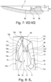
Fig. 7 einen Schnitt entlang der Linie VII-VII derFig. 3 , -
Fig. 8 eine Ansicht gemäß der inFig. 3 durch den Pfeil S8 angedeuteten Sichtrichtung, -
Fig. 9 eine Ansicht gemäß der inFig. 3 durch den Pfeil S9 angedeuteten Sichtrichtung, -
Fig. 10 eine Ansicht gemäß der inFig. 3 durch den Pfeil S10 angedeuteten Sichtrichtung, -
Fig. 11 eine Ansicht gemäß der inFig. 3 durch den Pfeil S11 angedeuteten Sichtrichtung, wobei die schulterseitige Profilrippe aufgeschnitten ist, -
Fig. 12 eine Ansicht gemäß der inFig. 3 durch den Pfeil S12 angedeuteten Sichtrichtung, wobei die schulterseitige Profilrippe aufgeschnitten ist, -
Fig. 13 eine Ansicht gemäß der inFig. 3 durch den Pfeil S13 angedeuteten Sichtrichtung und -
Fig. 14 einen Schnitt entlang der Linie XIV-XIV derFig. 3 .
-
1 a simplified plan view of a peripheral section of a shoulder-side profile rib of a tread strip of a pneumatic vehicle tire developed in the plane with an embodiment variant of the invention, -
2 a section along the line II-II of the1 , -
3 an enlarged top view of detail Z 3 of FIG1 , -
4 a section along the line IV-IV of the3 , -
figure 5 a section along the line VV the3 , -
6 a section along the line VI-VI of3 , -
7 a section along the line VII-VII of3 , -
8 a view according to in3 direction indicated by the arrow S 8 , -
9 a view according to in3 direction indicated by the arrow S 9 , -
10 a view according to in3 direction indicated by the arrow S 10 , -
11 a view according to in3 viewing direction indicated by the arrow S 11 , with the profile rib on the shoulder being cut open, -
12 a view according to in3 viewing direction indicated by the arrow S 12 , with the profile rib on the shoulder being cut open, -
13 a view according to in3 by the arrow S 13 indicated viewing direction and -
14 a section along the line XIV-XIV of the3 .
Gemäß der Erfindung ausgeführte Fahrzeugluftreifen sind Reifen für Kraftfahrzeuge, insbesondere für mehrspurige Kraftfahrzeuge, sowie vorzugsweise Reifen in Radialbauart für Personenkraftwagen, Vans oder Light-Trucks (Kleintransporter mit zGM ≤ 3,5 t, Leichte LKWs mit zGM ≤ 7,5 t).Pneumatic vehicle tires designed according to the invention are tires for motor vehicles, in particular for multi-track motor vehicles, and preferably radial tires for passenger cars, vans or light trucks (small vans with ZGM ≤3.5 t, light trucks with ZGM ≤7.5 t).
Die schulterseitige Umfangsrille 2 ist in radialer Richtung auf die jeweils vorgesehene Profiltiefe TUR (
Die schulterseitige Profilrippe 1 weist eine in der Laufstreifenperipherie liegende Rippenaußenfläche 1c, einen innerhalb der Bodenaufstandsfläche verlaufenden Rippeninnenabschnitt 1a mit einer am Niveau der Rippenaußenfläche 1c in axialer Richtung ermittelten Breite ba (
Gemäß
Die weitere Ausgestaltung der Querrillen 3, 4 wird nachfolgend anhand von einzelnen Querrillen 3, 4 beschrieben.The further configuration of the
Gemäß
Die Querrille 3, 4 setzt sich, in Draufsicht und in axialer Richtung betrachtet, aus einem im Rippeninnenabschnitt 1a und im Rippenaußenabschnitt 1b verlaufenden Rillenhauptabschnitt 5 und einem ausschließlich im Rippeninnenabschnitt 1a ausgebildeten Rillenendabschnitt 6 (Querrille 3), 7 (Querrille 4) zusammen. Die Querrille 3, 4 ist durch einen Rillengrund 8, eine Rillenwand 9 und eine Rillenwand 10 begrenzt, wobei die Rillenwand 9 von einer an der Rippenaußenfläche 1c liegenden Rillenkante 11 und die Rillenwand 10 von einer an der Rippenaußenfläche 1c liegenden Rillenkante 12 ausgeht. Die Orientierung der Querrillen 3, 4 ist derart, dass in Umfangsrichtung je eine Rillenkante 11 abwechselnd auf eine Rillenkante 12 folgt.The
Die Rillenkante 11 setzt sich, in Draufsicht betrachtet, aus einem über den Rillenhauptabschnitt 5 reichenden, gerade verlaufenden Kantenhauptabschnitt 11a und einem über den Rillenendabschnitt 6, 7 reichenden Kantenendabschnitt 11b (Querrille 3) bzw. 11b' (Querrille 4) zusammen und weist am gegenseitigen Anschlussbereich der Kantenabschnitte 11a, 11b bzw. 11a, 11b' eine Knickstelle 11k auf, an welcher die Kantenabschnitte 11a, 11b bzw. 11a, 11b' miteinander einen in Draufsicht über den Bereich der Querrille 3, 4 gemessenen Winkel β von 150° bis 165° einschließen. Die "Teilung" der Querrille 3, 4 in den Rillenhauptabschnitt 5 und den Rillenendabschnitt 6 bzw. 7 erfolgt entlang einer in Draufsicht in Umfangsrichtung durch die Knickstelle 10k verlaufenden Linie L2. Der Rillenhauptabschnitt 5 weist innerhalb der Bodenaufstandsfläche eine an der Rippenaußenfläche 1c ermittelte, in axialer Richtung projizierte Länge c1 von 55% bis 80% der erwähnten Länge cQR der zugehörigen Querrille 3, 4 und der Rillenendabschnitt 6 bzw. 7 weist eine an der Rippenaußenfläche 1c ermittelte, in axialer Richtung projizierte Länge c2 auf, wobei sich die Länge c2 aus der jeweiligen Länge c1 und dem Abstand a2 (Querrille 3), a3 (Querrille 4) ergibt. Die Länge c1 des Rillenhauptabschnittes 5 der Querrille 3 beträgt vorzugsweise 55% bis 65% der Länge cQR der Querrille 3. Die Länge c1 des Rillenhauptabschnittes 5 der Querrille 4 beträgt vorzugsweise 70% bis 80% der Länge cQR der Querrille 4.The
Der Kantenabschnitt 11b (Rillenkante 11 der Querrille 3) setzt sich, in Draufsicht betrachtet, aus einem gerade verlaufenden, laufstreifenaußenseitigen Kantenunterabschnitt 11bI und einem zumindest abschnittsweise bogenförmig verlaufenden, laufstreifeninnenseitigen Kantenunterabschnitt 11bII zusammen. Der laufstreifeninnenseitige Kantenunterabschnitt 11bII weist eine an der Rippenaußenfläche 1c ermittelte, in axialer Richtung projizierte Länge c3 von 20% bis 26% der Länge c2 auf, wobei die Länge c3 bevorzugt mindestens 3,0 mm beträgt.The
Der Kantenabschnitt 11b' (Rillenkante 11 der Querrille 4) verläuft in Draufsicht gerade.The
Die Rillenkante 12 läuft laufstreifeninnenseitig mit der Rillenkante 11 zusammen und setzt sich, in Draufsicht betrachtet, aus einem über den Rillenhauptabschnitt 5 verlaufenden und in den Rillenendabschnitt 6, 7 hineinverlaufenden Kantenhauptabschnitt 12a und einem ausschließlich im Rillenendabschnitt 6, 7 verlaufenden Kantenendabschnitt 12b (Querrille 3), 12b' (Querrille 4) zusammen. Der Kantenhauptabschnitt 12a verläuft in Draufsicht derart leicht gebogen, dass eine die Enden des Kantenhauptabschnittes 12a verbindende, gerade Linie L3 innerhalb der Querrille 3, 4 liegt.The
Bei der Querrille 3 verläuft der Kantenendabschnitt 12b in Draufsicht bogenförmig, wobei dessen Krümmungsrichtung mit jener des Kantenhauptabschnittes 12a übereinstimmt und wobei der Kantenendabschnitt 12b tangential (knickpunktfrei) an den Kantenhauptabschnitt 12a anschließt. Bei der Querrille 3 verläuft die Rillenkante 12 somit auf wendepunktfreie Weise durchgehend gebogen (bogenförmig).In the
Bei der Querrille 4 verläuft der Kantenendabschnitt 12b' in Draufsicht gerade, schließt über eine Knickstelle 12k der Rillenkante 12 an den Kantenhauptabschnitt 12a an, wobei der Kantenhauptabschnitt 12a mit dem Kantendendabschnitt 12b' einen in Draufsicht über den Bereich der Querrille 4 gemessenen Winkel γ von 140° bis 150° einschließt. Der Winkel γ ist bezüglich einer nicht gezeigten, in Draufsicht an den Kantenhauptabschnitt 12a angelegten, durch die Knickstelle 12k verlaufenden Tangente ermittelt.In the case of the
Die Querrille 3, 4 weist an der Knickstelle 11k, 12k zwischen den Rillenkanten 11, 12 ihre in Umfangsrichtung ermittelte maximale Breite bQR (Breite an der breitesten Stelle) von 3,0 mm bis 8,0 mm, insbesondere von 4,0 mm bis 7,0 mm, auf. Ausgehend von der Stelle mit der maximalen Breite bQR nimmt die Breite der Querrille 3, 4 zu ihren Enden kontinuierlich ab.At the
Wie
Gemäß
Gemäß
Der Grundabschnitt 8a verläuft zwischen den Vorsprungflanken 9b, 10b sowie auf der Tiefe tQR der Querrille 3, 4 (vergl.
Gemäß
Gemäß
Gemäß
Gemäß
Gemäß
Wie
Die Schrägfläche 9a, 10a schließt an die jeweilige Vorsprungflanke 9b, 10b über eine gerade oder leicht bogenförmig verlaufende scharfe Vorsprungkante 13a, 14a (vergl.
Gemäß
Die Schrägflächen 9a , 10a weisen, im in Draufsicht in Umfangsrichtung ausgerichteten Querschnitt betrachtet, über die Erstreckung der Vorsprungkante 13a, 14a eine Breite bSF (
Gemäß
Die Erfindung ist auf das beschriebene Ausführungsbeispiel nicht beschränkt.The invention is not limited to the exemplary embodiment described.
Insbesondere können die beide Rillenkanten der Querrillen frei von Knickstellen sein, sodass die Querrillen keine wie im Zusammenhang mit dem Ausführungsbeispiel beschriebene Rillenabschnitte aufweisen. In der anderen Laufstreifenhälfte kann eine weitere schulterseitige Profilrippe mit erfindungsgemäß ausgeführten Querrillen vorgesehen sein.In particular, the two groove edges of the transverse grooves can be free of kinks, so that the transverse grooves do not have any groove sections as described in connection with the exemplary embodiment. Another profile rib on the shoulder side with transverse grooves designed according to the invention can be provided in the other half of the tread.
- 11
- schulterseitige Profilrippeshoulder profile rib
- 1a1a
- Rippeninnenabschnittrib inner section
- 1b1b
- Rippenaußenabschnittrib outer section
- 1c1c
- Rippenaußenflächerib outer surface
- 1d1d
- Rippenflankerib flank
- 1d'1d'
- Übergangsrundungtransition rounding
- 22
- schulterseitige Umfangsrilleshoulder circumferential groove
- 33
- Querrilletransverse groove
- 44
- Querrilletransverse groove
- 55
- Rillenhauptabschnittgroove main section
- 66
- Rillenendabschnittgroove end section
- 77
- Rillenendabschnittgroove end section
- 88th
- Rillengrundgroove bottom
- 8a8a
- Grundabschnittbase section
- 8b8b
- Grundabschnittbase section
- 99
- Rillenwandgroove wall
- 9a9a
- Schrägflächebevel
- 9aI9aI
- Flächenauslaufsurface outlet
- 9b9b
- Vorsprungflankeleading edge
- 9c9c
- Endflächeend face
- 9d9d
- Wandabschnittwall section
- 9dI9dI
- Wandabschnittsbereichwall section area
- 9dII9dII
- Wandabschnittsbereichwall section area
- 1010
- Rillenwandgroove wall
- 10a10a
- Schrägflächebevel
- 10aI10aI
- Flächenauslaufsurface outlet
- 10b10b
- Vorsprungflankeleading edge
- 10c10c
- Endflächeend face
- 10d10d
- Wandabschnittwall section
- 10dI10dI
- Wandabschnittsbereichwall section area
- 10dII10dII
- Wandabschnittsbereichwall section area
- 1111
- Rillenkantegroove edge
- 11a11a
- Kantenhauptabschnittedge main section
- 11aI11aI
- innenseitiger Abschnittteilinside section part
- 11b11b
- Kantenendabschnittedge end section
- 11bI11bI
- laufstreifenaußenseitiger Kantenunterabschnitttread outside edge subsection
- 11bII11bII
- laufstreifeninnenseitiger Kantenunterabschnittinner tread edge subsection
- 11b'11b'
- Kantenendabschnittedge end section
- 11k11k
- Knickstellekink
- 1212
- Rillenkantegroove edge
- 12a12a
- Kantenhauptabschnittedge main section
- 12aI12aI
- innenseitiger Abschnittteilinside section part
- 12b12b
- Kantenendabschnittedge end section
- 12b'12b'
- Kantenendabschnittedge end section
- 12k12k
- Knickstellekink
- 1313
- Vorsprunghead Start
- 13a13a
- Vorsprungkanteledge edge
- 1414
- Vorsprunghead Start
- 14a14a
- Vorsprungkanteledge edge
- 1515
- Rillenverengunggroove narrowing
- 1616
- Übergangsrundungtransition rounding
- a1, a2, a3a1, a2, a3
- AbstandDistance
- ba, bSF, bRVba, bSF, bRV
- BreiteBroad
- bQRbQR
- maximale Breitemaximum width
- c1, c2, c3, c4, cQRc1, c2, c3, c4, cQR
- Längelength
- LL
- Linie (seitlicher Rand der Bodenaufstandsfläche)line (lateral edge of ground contact area)
- L1,L2,L3,L4L1,L2,L3,L4
- Linieline
- S8, S9, S10, S11, S12, S13S8, S9, S10, S11, S12, S13
- Pfeil (Sichtrichtung)arrow (direction of view)
- tQRtQR
- maximale Tiefemaximum depth
- tb, tVKtb, tVK
- Tiefedepth
- tVK, MIN, tVK, MAXtVK, MIN, tVK, MAX
- WertValue
- TURDOOR
- Profiltiefetread depth
- Z3Z3
- Detaildetail
- α, β, γ, δ, ε, η, θ, kα, β, γ, δ, ε, η, θ, k
- Winkelangle
Claims (15)
dadurch gekennzeichnet,
dass in jeder Querrille (3, 4) innerhalb des Rippeninnenabschnittes (1a) zwei in radialer Richtung von den Schrägflächen (9a, 10a) begrenzte Vorsprünge (13, 14) ausgebildet sind, wobei die Schrägflächen (9a, 10a) an am laufstreifeninnenseitigen Ende der Querrille (3, 4) zusammenlaufenden Wandabschnitten (9d, 10d) der Rillenwände (9, 10) auslaufen und wobei zwischen den Vorsprüngen (13, 14) eine laufstreifeninnenseitig über die Vorsprünge (13, 14) hinausverlaufende, von den zusammenlaufenden Wandabschnitten (9d, 10d) mitbegrenzte Rillenverengung (15) der Querrille (3, 4) verbleibt.Pneumatic vehicle tire with a tread strip with at least one shoulder-side profile rib (1) delimited by a circumferential groove (2) with an inner rib section (1a) running inside the ground contact area and an outer rib section (1b) running outside the ground contact area, wherein in the shoulder-side profile rib (1) both in inner rib section (1a) and transverse grooves (3, 4) running in the outer rib section (1b) and ending in front of the shoulder-side circumferential groove (2) with a maximum width (b QR ) of 3.0 mm to 8.0 mm determined in the circumferential direction , each transverse groove (3, 4) having a groove base (8) and two groove walls (9, 10) starting from a respective groove edge (11, 12), each with a single wall (9, 10) starting from the groove edge (11, 12) in the direction of extension of the Transverse groove (3, 4) are delimited by an elongated inclined surface (9a, 10a),
characterized,
that in each transverse groove (3, 4) within the inner section (1a) of the rib, two projections (13, 14) delimited in the radial direction by the inclined surfaces (9a, 10a) are formed, the inclined surfaces (9a, 10a) on the inside end of the tread strip Wall sections (9d, 10d) of the groove walls (9, 10) that converge in the transverse groove (3, 4) and wherein between the projections (13, 14) a 10d) limited groove constriction (15) of the transverse groove (3, 4) remains.
laufstreifeninnenseitigen Ende in radialer Richtung in einer Tiefe (tb) von 1,0 mm bis 3,0 mm endet.Pneumatic vehicle tire according to one of Claims 1 to 6, characterized in that the converging wall sections (9d, 10d) of the groove walls (9, 10) adjoin a base section (8b) of the groove base (8) which, in longitudinal section through the transverse groove (3rd , 4) considered, at his
Inside the tread end in the radial direction at a depth (t b ) of 1.0 mm to 3.0 mm.
Applications Claiming Priority (1)
| Application Number | Priority Date | Filing Date | Title |
|---|---|---|---|
| DE102021214496.9A DE102021214496A1 (en) | 2021-12-16 | 2021-12-16 | Vehicle Pneumatic Tires |
Publications (1)
| Publication Number | Publication Date |
|---|---|
| EP4197816A1 true EP4197816A1 (en) | 2023-06-21 |
Family
ID=83994901
Family Applications (1)
| Application Number | Title | Priority Date | Filing Date |
|---|---|---|---|
| EP22203321.9A Pending EP4197816A1 (en) | 2021-12-16 | 2022-10-24 | Pneumatic tyre for vehicles |
Country Status (2)
| Country | Link |
|---|---|
| EP (1) | EP4197816A1 (en) |
| DE (1) | DE102021214496A1 (en) |
Citations (3)
| Publication number | Priority date | Publication date | Assignee | Title |
|---|---|---|---|---|
| EP3388256B1 (en) * | 2017-04-13 | 2019-11-06 | Continental Reifen Deutschland GmbH | Pneumatic tyres for a vehicle |
| DE102019206654A1 (en) | 2019-05-08 | 2020-11-12 | Continental Reifen Deutschland Gmbh | Pneumatic vehicle tires |
| CN109789737B (en) * | 2016-09-30 | 2021-05-04 | 大陆轮胎德国有限公司 | Pneumatic tire for vehicle |
-
2021
- 2021-12-16 DE DE102021214496.9A patent/DE102021214496A1/en active Pending
-
2022
- 2022-10-24 EP EP22203321.9A patent/EP4197816A1/en active Pending
Patent Citations (3)
| Publication number | Priority date | Publication date | Assignee | Title |
|---|---|---|---|---|
| CN109789737B (en) * | 2016-09-30 | 2021-05-04 | 大陆轮胎德国有限公司 | Pneumatic tire for vehicle |
| EP3388256B1 (en) * | 2017-04-13 | 2019-11-06 | Continental Reifen Deutschland GmbH | Pneumatic tyres for a vehicle |
| DE102019206654A1 (en) | 2019-05-08 | 2020-11-12 | Continental Reifen Deutschland Gmbh | Pneumatic vehicle tires |
Also Published As
| Publication number | Publication date |
|---|---|
| DE102021214496A1 (en) | 2023-06-22 |
Similar Documents
| Publication | Publication Date | Title |
|---|---|---|
| EP3256333B1 (en) | Pneumatic tyre for a vehicle | |
| EP3383670B1 (en) | Pneumatic vehicle tyres | |
| EP3388256A1 (en) | Pneumatic tyres for a vehicle | |
| EP3181378A1 (en) | Pneumatic tyre | |
| EP3383669B1 (en) | Pneumatic vehicle tires | |
| EP3277523B1 (en) | Pneumatic vehicle tyre | |
| DE102019206654A1 (en) | Pneumatic vehicle tires | |
| EP3750723B1 (en) | Pneumatic tyre | |
| EP3628511B1 (en) | Pneumatic tyre | |
| EP3450213A1 (en) | Pneumatic tyre for a vehicle | |
| EP2138328B1 (en) | Pneumatic tyres for a vehicle | |
| EP4197816A1 (en) | Pneumatic tyre for vehicles | |
| EP3519208A1 (en) | Pneumatic vehicle tyres | |
| EP3659827B1 (en) | Pneumatic vehicle pneumatic tyre having an undercut tread | |
| EP3621822B1 (en) | Tread profile of a vehicle tire | |
| EP3888951B1 (en) | Pneumatic tyre | |
| EP4234273A1 (en) | Pneumatic tyre for vehicles | |
| EP4227117A1 (en) | Pneumatic tyre for vehicles | |
| EP1695845A1 (en) | Tyre with a tread profile | |
| DE102021200630A1 (en) | Vehicle Pneumatic Tires | |
| EP4363243A1 (en) | Pneumatic vehicle tyre | |
| WO2022184299A1 (en) | Pneumatic tyre for a vehicle | |
| EP4173847A1 (en) | Pneumatic tyre for vehicles | |
| EP4140776A1 (en) | Pneumatic tyre for vehicles | |
| WO2024041705A1 (en) | Pneumatic vehicle tire |
Legal Events
| Date | Code | Title | Description |
|---|---|---|---|
| PUAI | Public reference made under article 153(3) epc to a published international application that has entered the european phase |
Free format text: ORIGINAL CODE: 0009012 |
|
| STAA | Information on the status of an ep patent application or granted ep patent |
Free format text: STATUS: THE APPLICATION HAS BEEN PUBLISHED |
|
| AK | Designated contracting states |
Kind code of ref document: A1 Designated state(s): AL AT BE BG CH CY CZ DE DK EE ES FI FR GB GR HR HU IE IS IT LI LT LU LV MC ME MK MT NL NO PL PT RO RS SE SI SK SM TR |
|
| STAA | Information on the status of an ep patent application or granted ep patent |
Free format text: STATUS: REQUEST FOR EXAMINATION WAS MADE |
|
| 17P | Request for examination filed |
Effective date: 20231221 |
|
| RBV | Designated contracting states (corrected) |
Designated state(s): AL AT BE BG CH CY CZ DE DK EE ES FI FR GB GR HR HU IE IS IT LI LT LU LV MC ME MK MT NL NO PL PT RO RS SE SI SK SM TR |
|
| RAP3 | Party data changed (applicant data changed or rights of an application transferred) |
Owner name: CONTINENTAL REIFEN DEUTSCHLAND GMBH |