EP4197812A1 - Tire with reinforced sidewall layer - Google Patents
Tire with reinforced sidewall layer Download PDFInfo
- Publication number
- EP4197812A1 EP4197812A1 EP22212318.4A EP22212318A EP4197812A1 EP 4197812 A1 EP4197812 A1 EP 4197812A1 EP 22212318 A EP22212318 A EP 22212318A EP 4197812 A1 EP4197812 A1 EP 4197812A1
- Authority
- EP
- European Patent Office
- Prior art keywords
- cord
- tire
- twist
- aramid
- per
- Prior art date
- Legal status (The legal status is an assumption and is not a legal conclusion. Google has not performed a legal analysis and makes no representation as to the accuracy of the status listed.)
- Granted
Links
Images


Classifications
-
- B—PERFORMING OPERATIONS; TRANSPORTING
- B60—VEHICLES IN GENERAL
- B60C—VEHICLE TYRES; TYRE INFLATION; TYRE CHANGING; CONNECTING VALVES TO INFLATABLE ELASTIC BODIES IN GENERAL; DEVICES OR ARRANGEMENTS RELATED TO TYRES
- B60C9/00—Reinforcements or ply arrangement of pneumatic tyres
- B60C9/18—Structure or arrangement of belts or breakers, crown-reinforcing or cushioning layers
- B60C9/1821—Structure or arrangement of belts or breakers, crown-reinforcing or cushioning layers comprising discrete fibres or filaments
-
- B—PERFORMING OPERATIONS; TRANSPORTING
- B60—VEHICLES IN GENERAL
- B60C—VEHICLE TYRES; TYRE INFLATION; TYRE CHANGING; CONNECTING VALVES TO INFLATABLE ELASTIC BODIES IN GENERAL; DEVICES OR ARRANGEMENTS RELATED TO TYRES
- B60C13/00—Tyre sidewalls; Protecting, decorating, marking, or the like, thereof
- B60C13/002—Protection against exterior elements
-
- B—PERFORMING OPERATIONS; TRANSPORTING
- B60—VEHICLES IN GENERAL
- B60C—VEHICLE TYRES; TYRE INFLATION; TYRE CHANGING; CONNECTING VALVES TO INFLATABLE ELASTIC BODIES IN GENERAL; DEVICES OR ARRANGEMENTS RELATED TO TYRES
- B60C15/00—Tyre beads, e.g. ply turn-up or overlap
- B60C15/0009—Tyre beads, e.g. ply turn-up or overlap features of the carcass terminal portion
- B60C15/0018—Tyre beads, e.g. ply turn-up or overlap features of the carcass terminal portion not folded around the bead core, e.g. floating or down ply
-
- B—PERFORMING OPERATIONS; TRANSPORTING
- B60—VEHICLES IN GENERAL
- B60C—VEHICLE TYRES; TYRE INFLATION; TYRE CHANGING; CONNECTING VALVES TO INFLATABLE ELASTIC BODIES IN GENERAL; DEVICES OR ARRANGEMENTS RELATED TO TYRES
- B60C9/00—Reinforcements or ply arrangement of pneumatic tyres
- B60C9/0042—Reinforcements made of synthetic materials
-
- B—PERFORMING OPERATIONS; TRANSPORTING
- B60—VEHICLES IN GENERAL
- B60C—VEHICLE TYRES; TYRE INFLATION; TYRE CHANGING; CONNECTING VALVES TO INFLATABLE ELASTIC BODIES IN GENERAL; DEVICES OR ARRANGEMENTS RELATED TO TYRES
- B60C9/00—Reinforcements or ply arrangement of pneumatic tyres
- B60C9/005—Reinforcements made of different materials, e.g. hybrid or composite cords
-
- B—PERFORMING OPERATIONS; TRANSPORTING
- B60—VEHICLES IN GENERAL
- B60C—VEHICLE TYRES; TYRE INFLATION; TYRE CHANGING; CONNECTING VALVES TO INFLATABLE ELASTIC BODIES IN GENERAL; DEVICES OR ARRANGEMENTS RELATED TO TYRES
- B60C9/00—Reinforcements or ply arrangement of pneumatic tyres
- B60C9/02—Carcasses
- B60C9/04—Carcasses the reinforcing cords of each carcass ply arranged in a substantially parallel relationship
- B60C9/08—Carcasses the reinforcing cords of each carcass ply arranged in a substantially parallel relationship the cords extend transversely from bead to bead, i.e. radial ply
- B60C9/09—Carcasses the reinforcing cords of each carcass ply arranged in a substantially parallel relationship the cords extend transversely from bead to bead, i.e. radial ply combined with other carcass plies having cords extending diagonally from bead to bead, i.e. combined radial ply and bias angle ply
-
- B—PERFORMING OPERATIONS; TRANSPORTING
- B60—VEHICLES IN GENERAL
- B60C—VEHICLE TYRES; TYRE INFLATION; TYRE CHANGING; CONNECTING VALVES TO INFLATABLE ELASTIC BODIES IN GENERAL; DEVICES OR ARRANGEMENTS RELATED TO TYRES
- B60C9/00—Reinforcements or ply arrangement of pneumatic tyres
- B60C2009/0071—Reinforcements or ply arrangement of pneumatic tyres characterised by special physical properties of the reinforcements
- B60C2009/0092—Twist structure
-
- B—PERFORMING OPERATIONS; TRANSPORTING
- B60—VEHICLES IN GENERAL
- B60C—VEHICLE TYRES; TYRE INFLATION; TYRE CHANGING; CONNECTING VALVES TO INFLATABLE ELASTIC BODIES IN GENERAL; DEVICES OR ARRANGEMENTS RELATED TO TYRES
- B60C9/00—Reinforcements or ply arrangement of pneumatic tyres
- B60C9/18—Structure or arrangement of belts or breakers, crown-reinforcing or cushioning layers
- B60C9/20—Structure or arrangement of belts or breakers, crown-reinforcing or cushioning layers built-up from rubberised plies each having all cords arranged substantially parallel
- B60C2009/2074—Physical properties or dimension of the belt cord
- B60C2009/2096—Twist structures
-
- B—PERFORMING OPERATIONS; TRANSPORTING
- B60—VEHICLES IN GENERAL
- B60C—VEHICLE TYRES; TYRE INFLATION; TYRE CHANGING; CONNECTING VALVES TO INFLATABLE ELASTIC BODIES IN GENERAL; DEVICES OR ARRANGEMENTS RELATED TO TYRES
- B60C13/00—Tyre sidewalls; Protecting, decorating, marking, or the like, thereof
- B60C2013/005—Physical properties of the sidewall rubber
Definitions
- the present invention relates to a tire with a reinforced sidewall layer, preferably a light truck or off-road tire. More particularly, the tire includes a tire structure for enhancing cut and/or puncture resistance of the tire.
- tires that have the ability to be driven on paved roads while carrying heavy loads without excessive noise yet also to be capable of being driven in heavy snow or wet roads. Often these tires will be driven in flooded and/or wet roadway conditions. Historically, tires have been able to meet one or two of the above-referenced design requirements but usually at the sacrifice of the other design features, such as cut/puncture resistance. It would be advantageous for a tire structure to reasonably resist cuts and/or punctures.
- the invention relates to a tire in accordance with claim 1.
- a tire in accordance with a preferred aspect of the present invention includes a tread, a crown reinforcement, a carcass reinforcement with at least one ply wound about a pair of bead cores and through two sidewalls of the tire, and a cut/puncture resistant sidewall layer disposed adjacent a part of the carcass reinforcement within one of the sidewalls, the cut/puncture sidewall layer being formed of a plurality of cords, each cord including one nylon cord having S 4-8 tpi (twists per 2.54 cm), one aramid cord having Z 4-8 tpi, and the nylon cord and the aramid cord being twisted together with S 3-7 tpi.
- the nylon cord has a S 5-7 tpi.
- the aramid cord has a Z 5-7 tpi.
- the nylon cord and aramid cord are twisted together with S 4-6 tpi.
- the nylon cord has a S 6 tpi.
- the aramid cord has a Z 6 tpi.
- the nylon cord and aramid cord are twisted together with a S 5 tpi.
- the twist of the nylon cord and the twist of the aramid cord are equal.
- the tire 10 has a tread 12 having, when configured annularly, an axis of rotation and first and second lateral edges 14, 16.
- the tire includes a carcass 70 with one or more plies 72 reinforced by preferably radially extending synthetic or metal cords and a pair of substantially inextensible bead cores 74, preferably an apex 76 radially outward from the bead cores 74, and preferably a belt structure 77 radially outward from the plies 72.
- the tire 10 preferably further has an air impervious innerliner 79 such as a halobutyl innerliner and a rubber chafer 78 as it is common in tubeless type tires.
- the tread 12 preferably has two circumferentially continuous grooves 20, 24. Interposed between the two circumferentially continuous grooves is a rib 30 extending continuously around the circumference of the tread 12.
- the rib 30 preferably has a plurality of circumferentially spaced hook-shaped semi-blind grooves 40 arranged in a first row 1 and a second row 2.
- the hook-shaped semi-blind grooves 40 of the first row 1 preferably originate at the circumferentially continuous groove 20 and the hook-shaped semi-blind grooves 40 of the second row 2 preferably originate from the circumferentially continuous groove 24.
- Each hook-shaped semi-blind groove 40 preferably extends obliquely into the rib 30, having a first open portion 41 intersecting a circumferential groove 20, 24 and a blind portion 42 extending from the open portion 41.
- a centerline 45 bisecting the two portions 41, 42 as used herein may define the inclination of the hook-shaped semi-blind grooves 40.
- the centerline 45 of the hook-shaped semi-blind grooves 40 is preferably inclined at an angle ⁇ in the range of from 30 degrees to 60 degrees relative to the equatorial plane EP of the tire 10.
- the equatorial plane EP lies midway between a pair of lateral tread edges 14, 16 and perpendicular to the axis of rotation of the tire 10.
- the blind portion 42 preferably extends to an end 47 at which point a sipe incision 50 extends further.
- the sipe incision 50 preferably has no or only a small width and is accordingly preferably closed when in the contact patch.
- the hook-shaped semi-blind grooves 40 preferably has a width in the range of from 2 mm to 9 mm.
- the width of the hook-shaped semi-blind grooves 40 preferably diminishes continuously from the groove portion adjacent the circumferentially extending grooves 20, 22, 24 toward the interior of the rib 30 and preferably varies between 5.0 mm and 7.5 mm at the intersection of the circumferentially continuous groove, and the width at the end portion of the semi-blind grooves preferably varies between 2.0 mm and 2.5 mm.
- the orientation of the hook-shaped semi-blind grooves 40 allows to direct fluids laterally inwardly and expel the fluid as the tire 10 rotates in the generally circumferential direction.
- noise generated by the tread 10 at the rib 30 is at least partially directed laterally inwardly and is expelled as the tire 10 rotates circumferentially from the blind portion 42.
- the shoulders of the tread 12 adjacent each lateral tread edge 14, 16 preferably have a rib 34, 36.
- the ribs 34, 36 preferably each have a plurality of circumferentially spaced curved grooves 46.
- Each curved groove 46 preferably originates at a circumferentially continuous groove 20, 24 and at its origin the curved groove 46 are preferably linearly aligned with a hook-shaped semi-blind groove 40 such that the originating open portion 41 is inclined similarly to the originating portion of the curved groove 46.
- the curved groove 46 may bend about 90 degrees relative to its origin and then open laterally over the tread shoulders. In each bend of the curved groove 46 may be a tie bar.
- Yarn and cord twisting is done using any appropriate equipment.
- a balanced twist that is, where the ply (yarn) twist is essentially equal to the cable (cord) twist, has been conventionally used.
- an unbalanced cord twist may be used as the physical properties and fatigue life are typically dominated by the cable twist, not the yarn ply twist.
- An exemplary yarn Denier of 500 to 6000 may be used.
- the Denier per filament is preferably 2 dpf (Denier per 30.48 cm), or of from 5 Denier per 30.48 cm to 10 Denier per 30.48 cm.
- the torques formed in dipped and calendered cord fabric in S and Z directions may offset/neutralize each other and eliminate processing challenges.
- the Z and S twisted alternate cords may also be utilized in steel cord plies. Conventionally, no more than five unbalanced twist S cords or five unbalanced twist Z cords may be adjacent to each other in a fabric, unless other measures are used to neutralize the torque imbalances of the cords in the fabric. Otherwise, roll up issues may be encountered.
- some conventional plies have included cords with reduced yarn twist while maintaining the conventional cord twist.
- a Z ply twist of 197 tpm (turns per meter) (5 tpi (turns per inch)) is used
- an S cord twist of 334 tpm to 472 tpm (8.5 to 12 tpi) may be used.
- yarn twists of 118 tpm to 472 tpm (3 to 12 tpi) may be used as long as the twist multiplier (TM) is 10 or less and the yarn twist is maintained less than the cord twist. It has been found, however, that treated fabric and reinforced rubber composites made with such cords may be difficult to process since the residual torque, caused by the unbalanced twist in the cords, causes the treated fabric, and sometimes the fabric reinforced composite, to roll up at the edges.
- the tire 10 in accordance with the present invention includes a reinforcement structure 101, 102 disposed in each sidewall 98, 99 of the tire 10.
- the reinforcement structures 101, 102 each define a compliant aramid/nylon hybrid fabric layer enabling sidewall impact energy to dissipate through the reinforcement structures 101, 102. By dissipating more energy through compliance, each sidewall 98, 99 helps to avoid tearing damage for projectiles to the tire 10.
- Hybrid cord constructions of a compliant aramid/nylon hybrid fabric 101, 102 preferably have unbalanced cord twists which accentuate the extensibility of the nylon in the hybrid during low strains of the load elongation curves of the constructions 101, 102, as similarly shown in U.S. Patent Nos. 9,688,100 and 6,959,534 .
- aramid and nylon cords have a lower twist for promoting this enveloping puncture resistance while the overall hybrid cord has a higher twist for promoting cut resistance.
- One example cord includes one nylon cord having S 4-8 tpi (twists per 2.54 cm), one aramid cord having Z 4-8 tpi, and the two cords twisted together with S 3-7 tpi.
- Another example cord includes one nylon cord having Z 4-8 tpi (twists per 2.54 cm), one aramid cord having S 4-8 tpi, and the two cords twisted together with Z 3-7 tpi.
- the example cord with the unbalanced twist, thereby exhibits a load elongation curve with extensibility similar to nylon in the low elongation part of the curve and high modulus and cut resistance of similar to aramid in the high elongation part of the curve.
- the cord thus exhibits both compliance and cut resistance.
Landscapes
- Engineering & Computer Science (AREA)
- Mechanical Engineering (AREA)
- Tires In General (AREA)
Abstract
Description
- The present invention relates to a tire with a reinforced sidewall layer, preferably a light truck or off-road tire. More particularly, the tire includes a tire structure for enhancing cut and/or puncture resistance of the tire.
- With the continuing rise in popularity of light trucks and off-road vehicles, there exists a need to provide tires that have the ability to be driven on paved roads while carrying heavy loads without excessive noise yet also to be capable of being driven in heavy snow or wet roads. Often these tires will be driven in flooded and/or wet roadway conditions. Historically, tires have been able to meet one or two of the above-referenced design requirements but usually at the sacrifice of the other design features, such as cut/puncture resistance. It would be advantageous for a tire structure to reasonably resist cuts and/or punctures.
- The invention relates to a tire in accordance with claim 1.
- Dependent claims refer to preferred embodiments of the invention.
- A tire in accordance with a preferred aspect of the present invention includes a tread, a crown reinforcement, a carcass reinforcement with at least one ply wound about a pair of bead cores and through two sidewalls of the tire, and a cut/puncture resistant sidewall layer disposed adjacent a part of the carcass reinforcement within one of the sidewalls, the cut/puncture sidewall layer being formed of a plurality of cords, each cord including one nylon cord having S 4-8 tpi (twists per 2.54 cm), one aramid cord having Z 4-8 tpi, and the nylon cord and the aramid cord being twisted together with S 3-7 tpi.
- According to another preferred aspect of the tire, the nylon cord has a S 5-7 tpi.
- According to still another preferred aspect of the tire, the aramid cord has a Z 5-7 tpi.
- According to yet another preferred aspect of the tire, the nylon cord and aramid cord are twisted together with S 4-6 tpi.
- According to still another preferred aspect of the tire, the nylon cord has a S 6 tpi.
- According to yet another preferred aspect of the tire, the aramid cord has a Z 6 tpi.
- According to still another preferred aspect of the tire, the nylon cord and aramid cord are twisted together with a S 5 tpi.
- According to yet another preferred aspect of the tire, the twist of the nylon cord and the twist of the aramid cord are equal.
-
-
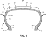
FIG. 1 is a schematic cross-sectional view of the tire in accordance with the present invention. -
FIG. 2 is a schematic perspective view of an example tread for use with the tire ofFIG. 1 . -
FIG. 3 is a schematic plan view of the example tread ofFIG. 2 . -
FIG. 4 is a schematic enlarged fragmentary view of the example tread ofFIG. 2 . - As used herein and in the claims:
- "Aramid" and "Aromatic polyamide" both mean a manufactured fiber in which the fiber-forming substance is generally recognized as a long chain of synthetic aromatic polyamide in which at least 85 percent of the amide linkages are attached directly to the two aromatic rings. Representative of an aramid or aromatic polyamide is a poly (p-phenyleneterephthalam ide).
- "Axial" and "axially" refer to lines or directions that are parallel to the axis of rotation of the tire.
- "Belt structure" means one or more layers or plies, woven or unwoven, underlying the tread, unanchored to the bead, and having cords inclined respect to the equatorial plane (EP) of the tire. The belt structure may also include plies of parallel cords inclined at relatively low angles, acting as restricting layers.
- "Circumferential" and "circumferentially" mean lines or directions extending along the perimeter of the surface of the annular tire parallel to the equatorial plane (EP) and perpendicular to the axial direction.
- "Cord" means one of the reinforcement strands which the reinforcement structures of the tire comprise.
- "Cord angle" means the acute angle, left or right in a plan view of the tire, formed by a cord with respect to the equatorial plane (EP). The "cord angle" is measured in a cured but uninflated tire.
- "Cord twist" means each yarn of the cord has its component filaments twisted together a given number of turns per unit of length of the yarn (usually expressed in turns per 2.54 cm (TPI) or turns per meter (TPM)) and additionally the yarns are twisted together a given number of turns per unit of length of the cord. The direction of twist refers to the direction of slope of the spirals of a yarn or cord when it is held vertically. If the slope of the spirals conforms in direction to the slope of the letter "S", then the twist is called "S" or "left hand". If the slope of the spirals conforms in direction to the slope of the letter "Z", then the twist is called "Z" or "right hand". An "S" or "left hand" twist direction is understood to be an opposite direction from a "Z" or "right hand" twist. "Yarn twist" is understood to mean the twist imparted to a yarn before the yarn is incorporated into a cord, and "cord twist" is understood to mean the twist imparted to two or more yarns when they are twisted together with one another to form a cord. "dtex" is understood to mean the weight in grams of 10,000 meters of a yarn before the yarn has a twist imparted thereto.
- "Denier" means the weight in grams per 9000 meters (unit for expressing linear density).
- "Dtex" means the weight in grams per 10,000 meters.
- "Equatorial plane (EP)" means the plane perpendicular to the tire's axis of rotation and passing through the center of its tread; or the plane containing the circumferential centerline of the tread.
- "Fabric" means a network of essentially unidirectionally extending cords, which may be twisted, and which in turn are composed of a plurality of a multiplicity of filaments (which may also be twisted) of a high modulus material.
- "Fiber" is a unit of matter, either natural or man-made, that forms the basic element of filaments; characterized by having a length at least 100 times its diameter or width.
- "Filament count" means the number of filaments that make up a yarn. Example: 1000 denier polyester has approximately 190 filaments.
- "Lateral" means an axial direction.
- "Monofilament" means a single, generally large filament of synthetic fiber
- "Outboard side" means the side of the tire farthest away from the vehicle when the tire is mounted on a wheel and the wheel is mounted on the vehicle.
- "Ply" means a cord-reinforced layer of rubber-coated radially deployed or otherwise parallel cords.
- "Radial" and "radially" mean directions radially toward or away from the axis of rotation of the tire.
- "Sidewall insert" means elastomer or cord reinforcements located in the sidewall region of a tire. The insert may be an addition to the carcass reinforcing ply and outer sidewall rubber that forms the outer surface of the tire.
- "Sidewall" means that portion of a tire between the tread and the bead.
- "Turns per 2.54 cm", or TPI, means turns of cord twist for each inch length of cord.
- "Yarn" is a generic term for a continuous strand of textile fibers or filaments. Yarn occurs in the following forms: (1) a number of fibers twisted together; (2) a number of filaments laid together without twist; (3) a number of filaments laid together with a degree of twist; (4) a single filament with or without twist (monofilament); and (5) a narrow strip of material with or without twist.
- With the reference to
FIGS. 1 through 4 , atire 10 in accordance with the present invention is shown. Thetire 10 has atread 12 having, when configured annularly, an axis of rotation and first and secondlateral edges carcass 70 with one ormore plies 72 reinforced by preferably radially extending synthetic or metal cords and a pair of substantiallyinextensible bead cores 74, preferably anapex 76 radially outward from thebead cores 74, and preferably abelt structure 77 radially outward from theplies 72. Thetire 10 preferably further has an airimpervious innerliner 79 such as a halobutyl innerliner and arubber chafer 78 as it is common in tubeless type tires. - The
tread 12 preferably has two circumferentiallycontinuous grooves rib 30 extending continuously around the circumference of thetread 12. Therib 30 preferably has a plurality of circumferentially spaced hook-shapedsemi-blind grooves 40 arranged in a first row 1 and a second row 2. The hook-shapedsemi-blind grooves 40 of the first row 1 preferably originate at the circumferentiallycontinuous groove 20 and the hook-shapedsemi-blind grooves 40 of the second row 2 preferably originate from the circumferentiallycontinuous groove 24. Each hook-shapedsemi-blind groove 40 preferably extends obliquely into therib 30, having a firstopen portion 41 intersecting acircumferential groove blind portion 42 extending from theopen portion 41. Acenterline 45 bisecting the twoportions semi-blind grooves 40. - The
centerline 45 of the hook-shapedsemi-blind grooves 40 is preferably inclined at an angle Θ in the range of from 30 degrees to 60 degrees relative to the equatorial plane EP of thetire 10. The equatorial plane EP lies midway between a pair of lateral tread edges 14, 16 and perpendicular to the axis of rotation of thetire 10. Theblind portion 42 preferably extends to anend 47 at which point asipe incision 50 extends further. Thesipe incision 50 preferably has no or only a small width and is accordingly preferably closed when in the contact patch. The hook-shapedsemi-blind grooves 40 preferably has a width in the range of from 2 mm to 9 mm. The width of the hook-shapedsemi-blind grooves 40 preferably diminishes continuously from the groove portion adjacent thecircumferentially extending grooves rib 30 and preferably varies between 5.0 mm and 7.5 mm at the intersection of the circumferentially continuous groove, and the width at the end portion of the semi-blind grooves preferably varies between 2.0 mm and 2.5 mm. - The orientation of the hook-shaped
semi-blind grooves 40 allows to direct fluids laterally inwardly and expel the fluid as thetire 10 rotates in the generally circumferential direction. Similarly, noise generated by thetread 10 at therib 30 is at least partially directed laterally inwardly and is expelled as thetire 10 rotates circumferentially from theblind portion 42. - The shoulders of the
tread 12 adjacent eachlateral tread edge rib ribs curved grooves 46. Eachcurved groove 46 preferably originates at a circumferentiallycontinuous groove curved groove 46 are preferably linearly aligned with a hook-shapedsemi-blind groove 40 such that the originatingopen portion 41 is inclined similarly to the originating portion of thecurved groove 46. Thecurved groove 46 may bend about 90 degrees relative to its origin and then open laterally over the tread shoulders. In each bend of thecurved groove 46 may be a tie bar. - Yarn and cord twisting is done using any appropriate equipment. A balanced twist, that is, where the ply (yarn) twist is essentially equal to the cable (cord) twist, has been conventionally used. However, an unbalanced cord twist may be used as the physical properties and fatigue life are typically dominated by the cable twist, not the yarn ply twist. An exemplary yarn Denier of 500 to 6000 may be used. The Denier per filament is preferably 2 dpf (Denier per 30.48 cm), or of from 5 Denier per 30.48 cm to 10 Denier per 30.48 cm.
- When cords have unbalanced S and Z twists used alternately in the cord fabric, the torques formed in dipped and calendered cord fabric in S and Z directions may offset/neutralize each other and eliminate processing challenges. The Z and S twisted alternate cords may also be utilized in steel cord plies. Conventionally, no more than five unbalanced twist S cords or five unbalanced twist Z cords may be adjacent to each other in a fabric, unless other measures are used to neutralize the torque imbalances of the cords in the fabric. Otherwise, roll up issues may be encountered.
- For example, some conventional plies have included cords with reduced yarn twist while maintaining the conventional cord twist. When a Z ply twist of 197 tpm (turns per meter) (5 tpi (turns per inch)) is used, an S cord twist of 334 tpm to 472 tpm (8.5 to 12 tpi) may be used. In another example, yarn twists of 118 tpm to 472 tpm (3 to 12 tpi) may be used as long as the twist multiplier (TM) is 10 or less and the yarn twist is maintained less than the cord twist. It has been found, however, that treated fabric and reinforced rubber composites made with such cords may be difficult to process since the residual torque, caused by the unbalanced twist in the cords, causes the treated fabric, and sometimes the fabric reinforced composite, to roll up at the edges.
- As shown in
FIG. 4 , thetire 10 in accordance with the present invention includes areinforcement structure sidewall tire 10. Thereinforcement structures reinforcement structures sidewall tire 10. Hybrid cord constructions of a compliant aramid/nylon hybrid fabric constructions U.S. Patent Nos. 9,688,100 6,959,534 . - During deformation of the tire sidewalls 98, 99, low loads at low elongation allow the
reinforcement structures sidewalls - Thus, in accordance with the present invention, aramid and nylon cords have a lower twist for promoting this enveloping puncture resistance while the overall hybrid cord has a higher twist for promoting cut resistance.
- One example cord includes one nylon cord having S 4-8 tpi (twists per 2.54 cm), one aramid cord having Z 4-8 tpi, and the two cords twisted together with S 3-7 tpi.
- Another example cord includes one nylon cord having Z 4-8 tpi (twists per 2.54 cm), one aramid cord having S 4-8 tpi, and the two cords twisted together with Z 3-7 tpi.
- The example cord, with the unbalanced twist, thereby exhibits a load elongation curve with extensibility similar to nylon in the low elongation part of the curve and high modulus and cut resistance of similar to aramid in the high elongation part of the curve. The cord thus exhibits both compliance and cut resistance.
Claims (15)
- A tire comprising a tread (12), a crown reinforcement (77), a carcass reinforcement with at least one ply (72) wound about a pair of bead cores (74) and through two sidewalls (98, 99) of the tire (10), wherein the tire (10) further comprises a sidewall layer as a reinforcement structure (101, 102) disposed adjacent a part of the carcass reinforcement (72) within at least one of the sidewalls (98, 99), the sidewall layer comprising a plurality of cords, each cord including:(i) one nylon cord having an S twist with from 4 to 8 twists per 2.54 cm, one aramid cord having a Z twist with from 4 to 8 twists per 2.54 cm, and the nylon cord and the aramid cord being twisted together with an S twist having from 3 to 7 twists per 2.54 cm; or(ii) one nylon cord having an Z twist with from 4 to 8 twists per 2.54 cm, one aramid cord having a S twist with from 4 to 8 twists per 2.54 cm, and the nylon cord and the aramid cord being twisted together with an Z twist having from 3 to 7 twists per 2.54 cm.
- The tire of claim 1 wherein the sidewall layer is cut resistant and/or puncture resistant.
- The tire of claim 1 or 2 wherein each of the two sidewalls (98, 99) of the tire (10) comprises said sidewall layer comprising said plurality of cords.
- The tire of claim 1 or 2 wherein only the sidewall (98, 99) on the axially outer side of the tire (10) when the tire (10) is mounted to a vehicle in accordance with its specification has said sidewall layer comprising said plurality of cords.
- The tire of claim 1 wherein the nylon cord has an S or Z twist respectively with from 5 to 7 twists per 2.54 cm.
- The tire of claim 1 wherein the aramid cord has an Z or S twist respectively with from 5 to 7 twists per 2.54 cm.
- The tire of claim 1 wherein the nylon cord and the aramid cord are twisted together with an S or Z twist respectively with from 4 to 6 twists per 2.54 cm.
- The tire of claim 1 wherein the nylon cord has an S or Z twist respectively with 6 twists per 2.54 cm.
- The tire of claim 1 wherein the aramid cord has an Z or S twist respectively with 6 twists per 2.54 cm.
- The tire of claim 1 wherein the nylon cord and the aramid cord are twisted together with an S or Z twist respectively with 5 twists per 2.54 cm.
- The tire in accordance with at least one of the previous claims wherein the twists per 2.54 cm of the nylon cord and the twists per 2.54 cm of the aramid cord are equal.
- The tire in accordance with at least one of the previous claims wherein the twists per 2.54 cm of the nylon cord and the twists per 2.54 cm of the aramid cord are lower than the twists per 2.54 cm the nylon cord and the aramid cord are twisted together.
- The tire in accordance with at least one of the previous claims wherein the twist per 2.54 cm of the nylon cord and the twist per 2.54 cm of the aramid cord is each from 0.5 to 2 twists per 2.54 cm lower than the twist per 2.54 cm the nylon cord and the aramid cord are twisted together.
- The tire in accordance with at least one of the previous claims wherein the twist per 2.54 cm of the nylon cord and the twist per 2.54 cm of the aramid cord is each 1 twist per 2.54 cm lower than the twist per 2.54 cm the nylon cord and the aramid cord are twisted together.
- The tire in accordance with at least one of the previous claims wherein the sidewall layer is an aramid/nylon hybrid fabric layer.
Applications Claiming Priority (1)
| Application Number | Priority Date | Filing Date | Title |
|---|---|---|---|
| US17/552,575 US20230191841A1 (en) | 2021-12-16 | 2021-12-16 | Light truck or off-road tire |
Publications (2)
| Publication Number | Publication Date |
|---|---|
| EP4197812A1 true EP4197812A1 (en) | 2023-06-21 |
| EP4197812B1 EP4197812B1 (en) | 2024-07-31 |
Family
ID=84462661
Family Applications (1)
| Application Number | Title | Priority Date | Filing Date |
|---|---|---|---|
| EP22212318.4A Active EP4197812B1 (en) | 2021-12-16 | 2022-12-08 | Tire with reinforced sidewall layer |
Country Status (2)
| Country | Link |
|---|---|
| US (1) | US20230191841A1 (en) |
| EP (1) | EP4197812B1 (en) |
Citations (5)
| Publication number | Priority date | Publication date | Assignee | Title |
|---|---|---|---|---|
| US6959534B2 (en) | 2000-01-24 | 2005-11-01 | The Goodyear Tire & Rubber Company | Reinforcement for rubber composites |
| EP2065223A1 (en) * | 2007-11-30 | 2009-06-03 | The Yokohama Rubber Co., Ltd. | Pneumatic radial tire |
| WO2010051299A1 (en) * | 2008-10-30 | 2010-05-06 | E. I. Du Pont De Nemours And Company | Non-load bearing cut resistant tire side-wall component, tire containing said component, and processes for making same |
| US20120097312A1 (en) * | 2010-10-22 | 2012-04-26 | Kiyoshi Ueyoko | Reduced weight aircraft tire |
| US9688100B2 (en) | 2012-10-18 | 2017-06-27 | Kordsa Global Endüstriyel Iplik Ve Kord Bezi Sanayi Ve Ticaret Anonim Sirketi | Tire cord fabric |
Family Cites Families (3)
| Publication number | Priority date | Publication date | Assignee | Title |
|---|---|---|---|---|
| US4877073A (en) * | 1988-02-17 | 1989-10-31 | The Goodyear Tire & Rubber Company | Cables and tires reinforced by said cables |
| FR2927845B1 (en) * | 2008-02-21 | 2010-03-19 | Michelin & Cie | PNEUMATIC TIRE FOR FLAT ROLL WITH ADDITIONAL FLANK REINFORCEMENT. |
| US20200122508A1 (en) * | 2017-06-30 | 2020-04-23 | Kolon Industries, Inc. | Rubber reinforcing material with reduced weight, method for preparing the same and tire comprising the same |
-
2021
- 2021-12-16 US US17/552,575 patent/US20230191841A1/en not_active Abandoned
-
2022
- 2022-12-08 EP EP22212318.4A patent/EP4197812B1/en active Active
Patent Citations (5)
| Publication number | Priority date | Publication date | Assignee | Title |
|---|---|---|---|---|
| US6959534B2 (en) | 2000-01-24 | 2005-11-01 | The Goodyear Tire & Rubber Company | Reinforcement for rubber composites |
| EP2065223A1 (en) * | 2007-11-30 | 2009-06-03 | The Yokohama Rubber Co., Ltd. | Pneumatic radial tire |
| WO2010051299A1 (en) * | 2008-10-30 | 2010-05-06 | E. I. Du Pont De Nemours And Company | Non-load bearing cut resistant tire side-wall component, tire containing said component, and processes for making same |
| US20120097312A1 (en) * | 2010-10-22 | 2012-04-26 | Kiyoshi Ueyoko | Reduced weight aircraft tire |
| US9688100B2 (en) | 2012-10-18 | 2017-06-27 | Kordsa Global Endüstriyel Iplik Ve Kord Bezi Sanayi Ve Ticaret Anonim Sirketi | Tire cord fabric |
Also Published As
| Publication number | Publication date |
|---|---|
| US20230191841A1 (en) | 2023-06-22 |
| EP4197812B1 (en) | 2024-07-31 |
Similar Documents
| Publication | Publication Date | Title |
|---|---|---|
| US11046112B2 (en) | Assembly for tire including impregnated woven or knitted fabric(s) and a sacrificial holder | |
| CN110300655B (en) | Assembly comprising a partially breakable fabric and a support structure | |
| JP2024026893A (en) | Tire assembly including a breakable structure and a support structure | |
| EP2604448B1 (en) | Composite cord and overlay ply for a pneumatic tire | |
| US20120168059A1 (en) | Pneumatic tire and method for making a pneumatic tire | |
| KR20090045077A (en) | Unidirectional Fabrics and Tires | |
| US20120085474A1 (en) | Pneumatic tire with a woven metallic reinforcement | |
| CN102811868B (en) | Pneumatic vehicle tire | |
| EP1097824A2 (en) | Radial tyre for motorcycle | |
| CN112976941B (en) | Belt structure for tire | |
| CN114590079A (en) | Fabric structure for tire | |
| US20120298278A1 (en) | Carcass ply structure for a pneumatic tire | |
| US20230066575A1 (en) | Shear band | |
| EP1112869B1 (en) | Continuous folded belt and splice therefore | |
| EP4197812B1 (en) | Tire with reinforced sidewall layer | |
| JP5245313B2 (en) | Pneumatic tire | |
| EP0565944B1 (en) | Pneumatic radial tire having two nonmetallic chippers | |
| CN109982866B (en) | Tyre for vehicle wheels | |
| US20230135243A1 (en) | Tire with specified cord construction | |
| US20220041016A1 (en) | Shearband structure for a tire | |
| US20210170795A1 (en) | Shear band | |
| CN113195256A (en) | Tyre for vehicle wheels | |
| US20220161601A1 (en) | Fabric structure for a tire | |
| US20130118670A1 (en) | Pneumatic tire with tackified wrapped reinforcement | |
| US20230055170A1 (en) | Aircraft tire |
Legal Events
| Date | Code | Title | Description |
|---|---|---|---|
| PUAI | Public reference made under article 153(3) epc to a published international application that has entered the european phase |
Free format text: ORIGINAL CODE: 0009012 |
|
| STAA | Information on the status of an ep patent application or granted ep patent |
Free format text: STATUS: THE APPLICATION HAS BEEN PUBLISHED |
|
| AK | Designated contracting states |
Kind code of ref document: A1 Designated state(s): AL AT BE BG CH CY CZ DE DK EE ES FI FR GB GR HR HU IE IS IT LI LT LU LV MC ME MK MT NL NO PL PT RO RS SE SI SK SM TR |
|
| STAA | Information on the status of an ep patent application or granted ep patent |
Free format text: STATUS: REQUEST FOR EXAMINATION WAS MADE |
|
| 17P | Request for examination filed |
Effective date: 20231221 |
|
| RBV | Designated contracting states (corrected) |
Designated state(s): AL AT BE BG CH CY CZ DE DK EE ES FI FR GB GR HR HU IE IS IT LI LT LU LV MC ME MK MT NL NO PL PT RO RS SE SI SK SM TR |
|
| RIC1 | Information provided on ipc code assigned before grant |
Ipc: B60C 9/09 20060101ALI20240118BHEP Ipc: B60C 15/00 20060101ALI20240118BHEP Ipc: B60C 13/00 20060101ALI20240118BHEP Ipc: B60C 9/00 20060101AFI20240118BHEP |
|
| GRAP | Despatch of communication of intention to grant a patent |
Free format text: ORIGINAL CODE: EPIDOSNIGR1 |
|
| STAA | Information on the status of an ep patent application or granted ep patent |
Free format text: STATUS: GRANT OF PATENT IS INTENDED |
|
| INTG | Intention to grant announced |
Effective date: 20240226 |
|
| GRAS | Grant fee paid |
Free format text: ORIGINAL CODE: EPIDOSNIGR3 |
|
| GRAA | (expected) grant |
Free format text: ORIGINAL CODE: 0009210 |
|
| STAA | Information on the status of an ep patent application or granted ep patent |
Free format text: STATUS: THE PATENT HAS BEEN GRANTED |
|
| AK | Designated contracting states |
Kind code of ref document: B1 Designated state(s): AL AT BE BG CH CY CZ DE DK EE ES FI FR GB GR HR HU IE IS IT LI LT LU LV MC ME MK MT NL NO PL PT RO RS SE SI SK SM TR |
|
| REG | Reference to a national code |
Ref country code: CH Ref legal event code: EP Ref country code: GB Ref legal event code: FG4D |
|
| REG | Reference to a national code |
Ref country code: DE Ref legal event code: R096 Ref document number: 602022004983 Country of ref document: DE |
|
| REG | Reference to a national code |
Ref country code: IE Ref legal event code: FG4D |
|
| REG | Reference to a national code |
Ref country code: LT Ref legal event code: MG9D |
|
| REG | Reference to a national code |
Ref country code: NL Ref legal event code: MP Effective date: 20240731 |
|
| PG25 | Lapsed in a contracting state [announced via postgrant information from national office to epo] |
Ref country code: PT Free format text: LAPSE BECAUSE OF FAILURE TO SUBMIT A TRANSLATION OF THE DESCRIPTION OR TO PAY THE FEE WITHIN THE PRESCRIBED TIME-LIMIT Effective date: 20241202 |
|
| REG | Reference to a national code |
Ref country code: AT Ref legal event code: MK05 Ref document number: 1708142 Country of ref document: AT Kind code of ref document: T Effective date: 20240731 |
|
| PG25 | Lapsed in a contracting state [announced via postgrant information from national office to epo] |
Ref country code: PT Free format text: LAPSE BECAUSE OF FAILURE TO SUBMIT A TRANSLATION OF THE DESCRIPTION OR TO PAY THE FEE WITHIN THE PRESCRIBED TIME-LIMIT Effective date: 20241202 |
|
| PG25 | Lapsed in a contracting state [announced via postgrant information from national office to epo] |
Ref country code: NO Free format text: LAPSE BECAUSE OF FAILURE TO SUBMIT A TRANSLATION OF THE DESCRIPTION OR TO PAY THE FEE WITHIN THE PRESCRIBED TIME-LIMIT Effective date: 20241031 |
|
| PG25 | Lapsed in a contracting state [announced via postgrant information from national office to epo] |
Ref country code: GR Free format text: LAPSE BECAUSE OF FAILURE TO SUBMIT A TRANSLATION OF THE DESCRIPTION OR TO PAY THE FEE WITHIN THE PRESCRIBED TIME-LIMIT Effective date: 20241101 Ref country code: NL Free format text: LAPSE BECAUSE OF FAILURE TO SUBMIT A TRANSLATION OF THE DESCRIPTION OR TO PAY THE FEE WITHIN THE PRESCRIBED TIME-LIMIT Effective date: 20240731 Ref country code: FI Free format text: LAPSE BECAUSE OF FAILURE TO SUBMIT A TRANSLATION OF THE DESCRIPTION OR TO PAY THE FEE WITHIN THE PRESCRIBED TIME-LIMIT Effective date: 20240731 Ref country code: PL Free format text: LAPSE BECAUSE OF FAILURE TO SUBMIT A TRANSLATION OF THE DESCRIPTION OR TO PAY THE FEE WITHIN THE PRESCRIBED TIME-LIMIT Effective date: 20240731 |
|
| PG25 | Lapsed in a contracting state [announced via postgrant information from national office to epo] |
Ref country code: BG Free format text: LAPSE BECAUSE OF FAILURE TO SUBMIT A TRANSLATION OF THE DESCRIPTION OR TO PAY THE FEE WITHIN THE PRESCRIBED TIME-LIMIT Effective date: 20240731 |
|
| PG25 | Lapsed in a contracting state [announced via postgrant information from national office to epo] |
Ref country code: LV Free format text: LAPSE BECAUSE OF FAILURE TO SUBMIT A TRANSLATION OF THE DESCRIPTION OR TO PAY THE FEE WITHIN THE PRESCRIBED TIME-LIMIT Effective date: 20240731 |
|
| PG25 | Lapsed in a contracting state [announced via postgrant information from national office to epo] |
Ref country code: AT Free format text: LAPSE BECAUSE OF FAILURE TO SUBMIT A TRANSLATION OF THE DESCRIPTION OR TO PAY THE FEE WITHIN THE PRESCRIBED TIME-LIMIT Effective date: 20240731 Ref country code: IS Free format text: LAPSE BECAUSE OF FAILURE TO SUBMIT A TRANSLATION OF THE DESCRIPTION OR TO PAY THE FEE WITHIN THE PRESCRIBED TIME-LIMIT Effective date: 20241130 |
|
| PG25 | Lapsed in a contracting state [announced via postgrant information from national office to epo] |
Ref country code: HR Free format text: LAPSE BECAUSE OF FAILURE TO SUBMIT A TRANSLATION OF THE DESCRIPTION OR TO PAY THE FEE WITHIN THE PRESCRIBED TIME-LIMIT Effective date: 20240731 |
|
| PG25 | Lapsed in a contracting state [announced via postgrant information from national office to epo] |
Ref country code: RS Free format text: LAPSE BECAUSE OF FAILURE TO SUBMIT A TRANSLATION OF THE DESCRIPTION OR TO PAY THE FEE WITHIN THE PRESCRIBED TIME-LIMIT Effective date: 20241031 Ref country code: ES Free format text: LAPSE BECAUSE OF FAILURE TO SUBMIT A TRANSLATION OF THE DESCRIPTION OR TO PAY THE FEE WITHIN THE PRESCRIBED TIME-LIMIT Effective date: 20240731 |
|
| PG25 | Lapsed in a contracting state [announced via postgrant information from national office to epo] |
Ref country code: RS Free format text: LAPSE BECAUSE OF FAILURE TO SUBMIT A TRANSLATION OF THE DESCRIPTION OR TO PAY THE FEE WITHIN THE PRESCRIBED TIME-LIMIT Effective date: 20241031 Ref country code: PL Free format text: LAPSE BECAUSE OF FAILURE TO SUBMIT A TRANSLATION OF THE DESCRIPTION OR TO PAY THE FEE WITHIN THE PRESCRIBED TIME-LIMIT Effective date: 20240731 Ref country code: NO Free format text: LAPSE BECAUSE OF FAILURE TO SUBMIT A TRANSLATION OF THE DESCRIPTION OR TO PAY THE FEE WITHIN THE PRESCRIBED TIME-LIMIT Effective date: 20241031 Ref country code: NL Free format text: LAPSE BECAUSE OF FAILURE TO SUBMIT A TRANSLATION OF THE DESCRIPTION OR TO PAY THE FEE WITHIN THE PRESCRIBED TIME-LIMIT Effective date: 20240731 Ref country code: LV Free format text: LAPSE BECAUSE OF FAILURE TO SUBMIT A TRANSLATION OF THE DESCRIPTION OR TO PAY THE FEE WITHIN THE PRESCRIBED TIME-LIMIT Effective date: 20240731 Ref country code: IS Free format text: LAPSE BECAUSE OF FAILURE TO SUBMIT A TRANSLATION OF THE DESCRIPTION OR TO PAY THE FEE WITHIN THE PRESCRIBED TIME-LIMIT Effective date: 20241130 Ref country code: HR Free format text: LAPSE BECAUSE OF FAILURE TO SUBMIT A TRANSLATION OF THE DESCRIPTION OR TO PAY THE FEE WITHIN THE PRESCRIBED TIME-LIMIT Effective date: 20240731 Ref country code: GR Free format text: LAPSE BECAUSE OF FAILURE TO SUBMIT A TRANSLATION OF THE DESCRIPTION OR TO PAY THE FEE WITHIN THE PRESCRIBED TIME-LIMIT Effective date: 20241101 Ref country code: FI Free format text: LAPSE BECAUSE OF FAILURE TO SUBMIT A TRANSLATION OF THE DESCRIPTION OR TO PAY THE FEE WITHIN THE PRESCRIBED TIME-LIMIT Effective date: 20240731 Ref country code: ES Free format text: LAPSE BECAUSE OF FAILURE TO SUBMIT A TRANSLATION OF THE DESCRIPTION OR TO PAY THE FEE WITHIN THE PRESCRIBED TIME-LIMIT Effective date: 20240731 Ref country code: BG Free format text: LAPSE BECAUSE OF FAILURE TO SUBMIT A TRANSLATION OF THE DESCRIPTION OR TO PAY THE FEE WITHIN THE PRESCRIBED TIME-LIMIT Effective date: 20240731 Ref country code: AT Free format text: LAPSE BECAUSE OF FAILURE TO SUBMIT A TRANSLATION OF THE DESCRIPTION OR TO PAY THE FEE WITHIN THE PRESCRIBED TIME-LIMIT Effective date: 20240731 |
|
| PG25 | Lapsed in a contracting state [announced via postgrant information from national office to epo] |
Ref country code: RO Free format text: LAPSE BECAUSE OF FAILURE TO SUBMIT A TRANSLATION OF THE DESCRIPTION OR TO PAY THE FEE WITHIN THE PRESCRIBED TIME-LIMIT Effective date: 20240731 Ref country code: DK Free format text: LAPSE BECAUSE OF FAILURE TO SUBMIT A TRANSLATION OF THE DESCRIPTION OR TO PAY THE FEE WITHIN THE PRESCRIBED TIME-LIMIT Effective date: 20240731 Ref country code: SM Free format text: LAPSE BECAUSE OF FAILURE TO SUBMIT A TRANSLATION OF THE DESCRIPTION OR TO PAY THE FEE WITHIN THE PRESCRIBED TIME-LIMIT Effective date: 20240731 |
|
| PG25 | Lapsed in a contracting state [announced via postgrant information from national office to epo] |
Ref country code: EE Free format text: LAPSE BECAUSE OF FAILURE TO SUBMIT A TRANSLATION OF THE DESCRIPTION OR TO PAY THE FEE WITHIN THE PRESCRIBED TIME-LIMIT Effective date: 20240731 |
|
| PG25 | Lapsed in a contracting state [announced via postgrant information from national office to epo] |
Ref country code: CZ Free format text: LAPSE BECAUSE OF FAILURE TO SUBMIT A TRANSLATION OF THE DESCRIPTION OR TO PAY THE FEE WITHIN THE PRESCRIBED TIME-LIMIT Effective date: 20240731 |
|
| PG25 | Lapsed in a contracting state [announced via postgrant information from national office to epo] |
Ref country code: SK Free format text: LAPSE BECAUSE OF FAILURE TO SUBMIT A TRANSLATION OF THE DESCRIPTION OR TO PAY THE FEE WITHIN THE PRESCRIBED TIME-LIMIT Effective date: 20240731 |
|
| REG | Reference to a national code |
Ref country code: DE Ref legal event code: R097 Ref document number: 602022004983 Country of ref document: DE |
|
| PLBE | No opposition filed within time limit |
Free format text: ORIGINAL CODE: 0009261 |
|
| STAA | Information on the status of an ep patent application or granted ep patent |
Free format text: STATUS: NO OPPOSITION FILED WITHIN TIME LIMIT |
|
| PG25 | Lapsed in a contracting state [announced via postgrant information from national office to epo] |
Ref country code: MC Free format text: LAPSE BECAUSE OF FAILURE TO SUBMIT A TRANSLATION OF THE DESCRIPTION OR TO PAY THE FEE WITHIN THE PRESCRIBED TIME-LIMIT Effective date: 20240731 |
|
| 26N | No opposition filed |
Effective date: 20250501 |
|
| PG25 | Lapsed in a contracting state [announced via postgrant information from national office to epo] |
Ref country code: LU Free format text: LAPSE BECAUSE OF NON-PAYMENT OF DUE FEES Effective date: 20241208 |
|
| PG25 | Lapsed in a contracting state [announced via postgrant information from national office to epo] |
Ref country code: SE Free format text: LAPSE BECAUSE OF FAILURE TO SUBMIT A TRANSLATION OF THE DESCRIPTION OR TO PAY THE FEE WITHIN THE PRESCRIBED TIME-LIMIT Effective date: 20240731 |
|
| REG | Reference to a national code |
Ref country code: BE Ref legal event code: MM Effective date: 20241231 |
|
| PG25 | Lapsed in a contracting state [announced via postgrant information from national office to epo] |
Ref country code: BE Free format text: LAPSE BECAUSE OF NON-PAYMENT OF DUE FEES Effective date: 20241231 |
|
| PG25 | Lapsed in a contracting state [announced via postgrant information from national office to epo] |
Ref country code: IE Free format text: LAPSE BECAUSE OF NON-PAYMENT OF DUE FEES Effective date: 20241208 |
|
| PGFP | Annual fee paid to national office [announced via postgrant information from national office to epo] |
Ref country code: DE Payment date: 20251126 Year of fee payment: 4 |
|
| PGFP | Annual fee paid to national office [announced via postgrant information from national office to epo] |
Ref country code: FR Payment date: 20251119 Year of fee payment: 4 |
|
| PGFP | Annual fee paid to national office [announced via postgrant information from national office to epo] |
Ref country code: TR Payment date: 20251127 Year of fee payment: 4 |
|
| PGFP | Annual fee paid to national office [announced via postgrant information from national office to epo] |
Ref country code: IT Payment date: 20251231 Year of fee payment: 4 |