EP4197757A2 - Systems and methods for themoplastic panel manufacturing - Google Patents
Systems and methods for themoplastic panel manufacturing Download PDFInfo
- Publication number
- EP4197757A2 EP4197757A2 EP22212650.0A EP22212650A EP4197757A2 EP 4197757 A2 EP4197757 A2 EP 4197757A2 EP 22212650 A EP22212650 A EP 22212650A EP 4197757 A2 EP4197757 A2 EP 4197757A2
- Authority
- EP
- European Patent Office
- Prior art keywords
- panel
- preform
- manufacturing
- heating
- cure temperature
- Prior art date
- Legal status (The legal status is an assumption and is not a legal conclusion. Google has not performed a legal analysis and makes no representation as to the accuracy of the status listed.)
- Pending
Links
- 238000004519 manufacturing process Methods 0.000 title claims abstract description 28
- 238000000034 method Methods 0.000 title claims description 50
- 238000007596 consolidation process Methods 0.000 claims abstract description 41
- 229920001169 thermoplastic Polymers 0.000 claims abstract description 28
- 239000004416 thermosoftening plastic Substances 0.000 claims abstract description 28
- 239000000835 fiber Substances 0.000 claims abstract description 27
- 238000010438 heat treatment Methods 0.000 claims abstract description 27
- 239000000463 material Substances 0.000 claims abstract description 17
- 229920005992 thermoplastic resin Polymers 0.000 claims abstract description 16
- 229910001374 Invar Inorganic materials 0.000 claims description 34
- 230000013011 mating Effects 0.000 claims description 19
- 239000003795 chemical substances by application Substances 0.000 claims description 18
- 210000000569 greater omentum Anatomy 0.000 claims description 15
- 238000001816 cooling Methods 0.000 claims description 7
- 230000004044 response Effects 0.000 claims description 2
- -1 polyparaphenylene benzoxazole Polymers 0.000 description 12
- 229920000049 Carbon (fiber) Polymers 0.000 description 6
- 230000008901 benefit Effects 0.000 description 6
- 239000004917 carbon fiber Substances 0.000 description 6
- 229920005989 resin Polymers 0.000 description 6
- 239000011347 resin Substances 0.000 description 6
- 229920000728 polyester Polymers 0.000 description 5
- 239000012815 thermoplastic material Substances 0.000 description 5
- 239000004698 Polyethylene Substances 0.000 description 4
- 239000004642 Polyimide Substances 0.000 description 4
- 229920000573 polyethylene Polymers 0.000 description 4
- 229920001721 polyimide Polymers 0.000 description 4
- 239000004952 Polyamide Substances 0.000 description 3
- 239000004734 Polyphenylene sulfide Substances 0.000 description 3
- 229910052751 metal Inorganic materials 0.000 description 3
- 239000002184 metal Substances 0.000 description 3
- 229920002647 polyamide Polymers 0.000 description 3
- 229920000098 polyolefin Polymers 0.000 description 3
- 229920000069 polyphenylene sulfide Polymers 0.000 description 3
- 229920001343 polytetrafluoroethylene Polymers 0.000 description 3
- 239000004810 polytetrafluoroethylene Substances 0.000 description 3
- 230000008569 process Effects 0.000 description 3
- 229920000106 Liquid crystal polymer Polymers 0.000 description 2
- 239000004977 Liquid-crystal polymers (LCPs) Substances 0.000 description 2
- 239000002033 PVDF binder Substances 0.000 description 2
- 229930040373 Paraformaldehyde Natural products 0.000 description 2
- 239000004696 Poly ether ether ketone Substances 0.000 description 2
- 239000004697 Polyetherimide Substances 0.000 description 2
- 239000004743 Polypropylene Substances 0.000 description 2
- 239000004793 Polystyrene Substances 0.000 description 2
- UCKMPCXJQFINFW-UHFFFAOYSA-N Sulphide Chemical compound [S-2] UCKMPCXJQFINFW-UHFFFAOYSA-N 0.000 description 2
- 238000004891 communication Methods 0.000 description 2
- 239000012530 fluid Substances 0.000 description 2
- 229920001778 nylon Polymers 0.000 description 2
- 229920001652 poly(etherketoneketone) Polymers 0.000 description 2
- 229920003229 poly(methyl methacrylate) Polymers 0.000 description 2
- 229920002492 poly(sulfone) Polymers 0.000 description 2
- 229920002239 polyacrylonitrile Polymers 0.000 description 2
- 229920001230 polyarylate Polymers 0.000 description 2
- 229920000412 polyarylene Polymers 0.000 description 2
- 229920006260 polyaryletherketone Polymers 0.000 description 2
- 229920001707 polybutylene terephthalate Polymers 0.000 description 2
- 229920002530 polyetherether ketone Polymers 0.000 description 2
- 229920001601 polyetherimide Polymers 0.000 description 2
- 229920000139 polyethylene terephthalate Polymers 0.000 description 2
- 239000005020 polyethylene terephthalate Substances 0.000 description 2
- 229920001470 polyketone Polymers 0.000 description 2
- 239000004926 polymethyl methacrylate Substances 0.000 description 2
- 229920006324 polyoxymethylene Polymers 0.000 description 2
- 229920001955 polyphenylene ether Polymers 0.000 description 2
- 229920001155 polypropylene Polymers 0.000 description 2
- 229920002223 polystyrene Polymers 0.000 description 2
- 229920002981 polyvinylidene fluoride Polymers 0.000 description 2
- 239000012783 reinforcing fiber Substances 0.000 description 2
- 238000004381 surface treatment Methods 0.000 description 2
- 229920002972 Acrylic fiber Polymers 0.000 description 1
- NLHHRLWOUZZQLW-UHFFFAOYSA-N Acrylonitrile Chemical compound C=CC#N NLHHRLWOUZZQLW-UHFFFAOYSA-N 0.000 description 1
- 229910001369 Brass Inorganic materials 0.000 description 1
- OKTJSMMVPCPJKN-UHFFFAOYSA-N Carbon Chemical compound [C] OKTJSMMVPCPJKN-UHFFFAOYSA-N 0.000 description 1
- 239000004593 Epoxy Substances 0.000 description 1
- YCKRFDGAMUMZLT-UHFFFAOYSA-N Fluorine atom Chemical compound [F] YCKRFDGAMUMZLT-UHFFFAOYSA-N 0.000 description 1
- 239000004677 Nylon Substances 0.000 description 1
- 229920008285 Poly(ether ketone) PEK Polymers 0.000 description 1
- 229920012266 Poly(ether sulfone) PES Polymers 0.000 description 1
- 239000005062 Polybutadiene Substances 0.000 description 1
- 239000004721 Polyphenylene oxide Substances 0.000 description 1
- 229920000297 Rayon Polymers 0.000 description 1
- 229910052581 Si3N4 Inorganic materials 0.000 description 1
- 230000006978 adaptation Effects 0.000 description 1
- 239000000654 additive Substances 0.000 description 1
- 230000000996 additive effect Effects 0.000 description 1
- 229910052782 aluminium Inorganic materials 0.000 description 1
- XAGFODPZIPBFFR-UHFFFAOYSA-N aluminium Chemical compound [Al] XAGFODPZIPBFFR-UHFFFAOYSA-N 0.000 description 1
- 239000004760 aramid Substances 0.000 description 1
- 229920006231 aramid fiber Polymers 0.000 description 1
- 239000011230 binding agent Substances 0.000 description 1
- 239000010951 brass Substances 0.000 description 1
- 239000011304 carbon pitch Substances 0.000 description 1
- 239000002131 composite material Substances 0.000 description 1
- 238000010276 construction Methods 0.000 description 1
- 229920001577 copolymer Polymers 0.000 description 1
- 230000008878 coupling Effects 0.000 description 1
- 239000007822 coupling agent Substances 0.000 description 1
- 238000010168 coupling process Methods 0.000 description 1
- 238000005859 coupling reaction Methods 0.000 description 1
- 238000001723 curing Methods 0.000 description 1
- 230000008021 deposition Effects 0.000 description 1
- 239000011152 fibreglass Substances 0.000 description 1
- 229910052731 fluorine Inorganic materials 0.000 description 1
- 239000011737 fluorine Substances 0.000 description 1
- 239000003365 glass fiber Substances 0.000 description 1
- 229910002804 graphite Inorganic materials 0.000 description 1
- 239000010439 graphite Substances 0.000 description 1
- 239000012784 inorganic fiber Substances 0.000 description 1
- 229920005610 lignin Polymers 0.000 description 1
- 239000004973 liquid crystal related substance Substances 0.000 description 1
- VNWKTOKETHGBQD-UHFFFAOYSA-N methane Chemical compound C VNWKTOKETHGBQD-UHFFFAOYSA-N 0.000 description 1
- 238000013008 moisture curing Methods 0.000 description 1
- 150000002825 nitriles Chemical class 0.000 description 1
- 229920006287 phenoxy resin Polymers 0.000 description 1
- 239000013034 phenoxy resin Substances 0.000 description 1
- 229920002312 polyamide-imide Polymers 0.000 description 1
- 229920002857 polybutadiene Polymers 0.000 description 1
- 229920001748 polybutylene Polymers 0.000 description 1
- 239000004417 polycarbonate Substances 0.000 description 1
- 229920000515 polycarbonate Polymers 0.000 description 1
- 229920000570 polyether Polymers 0.000 description 1
- 239000011112 polyethylene naphthalate Substances 0.000 description 1
- 229920001195 polyisoprene Polymers 0.000 description 1
- 229920002635 polyurethane Polymers 0.000 description 1
- 239000004814 polyurethane Substances 0.000 description 1
- 239000004800 polyvinyl chloride Substances 0.000 description 1
- 230000001737 promoting effect Effects 0.000 description 1
- 230000001681 protective effect Effects 0.000 description 1
- 239000002964 rayon Substances 0.000 description 1
- 230000008439 repair process Effects 0.000 description 1
- 230000029058 respiratory gaseous exchange Effects 0.000 description 1
- HBMJWWWQQXIZIP-UHFFFAOYSA-N silicon carbide Chemical compound [Si+]#[C-] HBMJWWWQQXIZIP-UHFFFAOYSA-N 0.000 description 1
- 229910010271 silicon carbide Inorganic materials 0.000 description 1
- HQVNEWCFYHHQES-UHFFFAOYSA-N silicon nitride Chemical compound N12[Si]34N5[Si]62N3[Si]51N64 HQVNEWCFYHHQES-UHFFFAOYSA-N 0.000 description 1
- 238000004513 sizing Methods 0.000 description 1
- 239000002904 solvent Substances 0.000 description 1
- 229910001220 stainless steel Inorganic materials 0.000 description 1
- 239000010935 stainless steel Substances 0.000 description 1
- 229920002725 thermoplastic elastomer Polymers 0.000 description 1
- 238000003466 welding Methods 0.000 description 1
Images


Classifications
-
- B—PERFORMING OPERATIONS; TRANSPORTING
- B29—WORKING OF PLASTICS; WORKING OF SUBSTANCES IN A PLASTIC STATE IN GENERAL
- B29C—SHAPING OR JOINING OF PLASTICS; SHAPING OF MATERIAL IN A PLASTIC STATE, NOT OTHERWISE PROVIDED FOR; AFTER-TREATMENT OF THE SHAPED PRODUCTS, e.g. REPAIRING
- B29C70/00—Shaping composites, i.e. plastics material comprising reinforcements, fillers or preformed parts, e.g. inserts
- B29C70/04—Shaping composites, i.e. plastics material comprising reinforcements, fillers or preformed parts, e.g. inserts comprising reinforcements only, e.g. self-reinforcing plastics
- B29C70/28—Shaping operations therefor
- B29C70/40—Shaping or impregnating by compression not applied
- B29C70/42—Shaping or impregnating by compression not applied for producing articles of definite length, i.e. discrete articles
- B29C70/44—Shaping or impregnating by compression not applied for producing articles of definite length, i.e. discrete articles using isostatic pressure, e.g. pressure difference-moulding, vacuum bag-moulding, autoclave-moulding or expanding rubber-moulding
- B29C70/443—Shaping or impregnating by compression not applied for producing articles of definite length, i.e. discrete articles using isostatic pressure, e.g. pressure difference-moulding, vacuum bag-moulding, autoclave-moulding or expanding rubber-moulding and impregnating by vacuum or injection
-
- B—PERFORMING OPERATIONS; TRANSPORTING
- B29—WORKING OF PLASTICS; WORKING OF SUBSTANCES IN A PLASTIC STATE IN GENERAL
- B29C—SHAPING OR JOINING OF PLASTICS; SHAPING OF MATERIAL IN A PLASTIC STATE, NOT OTHERWISE PROVIDED FOR; AFTER-TREATMENT OF THE SHAPED PRODUCTS, e.g. REPAIRING
- B29C70/00—Shaping composites, i.e. plastics material comprising reinforcements, fillers or preformed parts, e.g. inserts
- B29C70/04—Shaping composites, i.e. plastics material comprising reinforcements, fillers or preformed parts, e.g. inserts comprising reinforcements only, e.g. self-reinforcing plastics
- B29C70/28—Shaping operations therefor
- B29C70/40—Shaping or impregnating by compression not applied
- B29C70/42—Shaping or impregnating by compression not applied for producing articles of definite length, i.e. discrete articles
- B29C70/44—Shaping or impregnating by compression not applied for producing articles of definite length, i.e. discrete articles using isostatic pressure, e.g. pressure difference-moulding, vacuum bag-moulding, autoclave-moulding or expanding rubber-moulding
-
- B—PERFORMING OPERATIONS; TRANSPORTING
- B29—WORKING OF PLASTICS; WORKING OF SUBSTANCES IN A PLASTIC STATE IN GENERAL
- B29C—SHAPING OR JOINING OF PLASTICS; SHAPING OF MATERIAL IN A PLASTIC STATE, NOT OTHERWISE PROVIDED FOR; AFTER-TREATMENT OF THE SHAPED PRODUCTS, e.g. REPAIRING
- B29C66/00—General aspects of processes or apparatus for joining preformed parts
- B29C66/004—Preventing sticking together, e.g. of some areas of the parts to be joined
- B29C66/0042—Preventing sticking together, e.g. of some areas of the parts to be joined of the joining tool and the parts to be joined
- B29C66/0044—Preventing sticking together, e.g. of some areas of the parts to be joined of the joining tool and the parts to be joined using a separating sheet, e.g. fixed on the joining tool
-
- B—PERFORMING OPERATIONS; TRANSPORTING
- B29—WORKING OF PLASTICS; WORKING OF SUBSTANCES IN A PLASTIC STATE IN GENERAL
- B29C—SHAPING OR JOINING OF PLASTICS; SHAPING OF MATERIAL IN A PLASTIC STATE, NOT OTHERWISE PROVIDED FOR; AFTER-TREATMENT OF THE SHAPED PRODUCTS, e.g. REPAIRING
- B29C66/00—General aspects of processes or apparatus for joining preformed parts
- B29C66/70—General aspects of processes or apparatus for joining preformed parts characterised by the composition, physical properties or the structure of the material of the parts to be joined; Joining with non-plastics material
- B29C66/73—General aspects of processes or apparatus for joining preformed parts characterised by the composition, physical properties or the structure of the material of the parts to be joined; Joining with non-plastics material characterised by the intensive physical properties of the material of the parts to be joined, by the optical properties of the material of the parts to be joined, by the extensive physical properties of the parts to be joined, by the state of the material of the parts to be joined or by the material of the parts to be joined being a thermoplastic or a thermoset
- B29C66/739—General aspects of processes or apparatus for joining preformed parts characterised by the composition, physical properties or the structure of the material of the parts to be joined; Joining with non-plastics material characterised by the intensive physical properties of the material of the parts to be joined, by the optical properties of the material of the parts to be joined, by the extensive physical properties of the parts to be joined, by the state of the material of the parts to be joined or by the material of the parts to be joined being a thermoplastic or a thermoset characterised by the material of the parts to be joined being a thermoplastic or a thermoset
- B29C66/7392—General aspects of processes or apparatus for joining preformed parts characterised by the composition, physical properties or the structure of the material of the parts to be joined; Joining with non-plastics material characterised by the intensive physical properties of the material of the parts to be joined, by the optical properties of the material of the parts to be joined, by the extensive physical properties of the parts to be joined, by the state of the material of the parts to be joined or by the material of the parts to be joined being a thermoplastic or a thermoset characterised by the material of the parts to be joined being a thermoplastic or a thermoset characterised by the material of at least one of the parts being a thermoplastic
-
- B—PERFORMING OPERATIONS; TRANSPORTING
- B29—WORKING OF PLASTICS; WORKING OF SUBSTANCES IN A PLASTIC STATE IN GENERAL
- B29C—SHAPING OR JOINING OF PLASTICS; SHAPING OF MATERIAL IN A PLASTIC STATE, NOT OTHERWISE PROVIDED FOR; AFTER-TREATMENT OF THE SHAPED PRODUCTS, e.g. REPAIRING
- B29C66/00—General aspects of processes or apparatus for joining preformed parts
- B29C66/80—General aspects of machine operations or constructions and parts thereof
- B29C66/81—General aspects of the pressing elements, i.e. the elements applying pressure on the parts to be joined in the area to be joined, e.g. the welding jaws or clamps
- B29C66/814—General aspects of the pressing elements, i.e. the elements applying pressure on the parts to be joined in the area to be joined, e.g. the welding jaws or clamps characterised by the design of the pressing elements, e.g. of the welding jaws or clamps
- B29C66/8145—General aspects of the pressing elements, i.e. the elements applying pressure on the parts to be joined in the area to be joined, e.g. the welding jaws or clamps characterised by the design of the pressing elements, e.g. of the welding jaws or clamps characterised by the constructional aspects of the pressing elements, e.g. of the welding jaws or clamps
- B29C66/81455—General aspects of the pressing elements, i.e. the elements applying pressure on the parts to be joined in the area to be joined, e.g. the welding jaws or clamps characterised by the design of the pressing elements, e.g. of the welding jaws or clamps characterised by the constructional aspects of the pressing elements, e.g. of the welding jaws or clamps being a fluid inflatable bag or bladder, a diaphragm or a vacuum bag for applying isostatic pressure
-
- B—PERFORMING OPERATIONS; TRANSPORTING
- B29—WORKING OF PLASTICS; WORKING OF SUBSTANCES IN A PLASTIC STATE IN GENERAL
- B29C—SHAPING OR JOINING OF PLASTICS; SHAPING OF MATERIAL IN A PLASTIC STATE, NOT OTHERWISE PROVIDED FOR; AFTER-TREATMENT OF THE SHAPED PRODUCTS, e.g. REPAIRING
- B29C66/00—General aspects of processes or apparatus for joining preformed parts
- B29C66/90—Measuring or controlling the joining process
- B29C66/91—Measuring or controlling the joining process by measuring or controlling the temperature, the heat or the thermal flux
- B29C66/914—Measuring or controlling the joining process by measuring or controlling the temperature, the heat or the thermal flux by controlling or regulating the temperature, the heat or the thermal flux
- B29C66/9141—Measuring or controlling the joining process by measuring or controlling the temperature, the heat or the thermal flux by controlling or regulating the temperature, the heat or the thermal flux by controlling or regulating the temperature
- B29C66/91411—Measuring or controlling the joining process by measuring or controlling the temperature, the heat or the thermal flux by controlling or regulating the temperature, the heat or the thermal flux by controlling or regulating the temperature of the parts to be joined, e.g. the joining process taking the temperature of the parts to be joined into account
-
- B—PERFORMING OPERATIONS; TRANSPORTING
- B29—WORKING OF PLASTICS; WORKING OF SUBSTANCES IN A PLASTIC STATE IN GENERAL
- B29C—SHAPING OR JOINING OF PLASTICS; SHAPING OF MATERIAL IN A PLASTIC STATE, NOT OTHERWISE PROVIDED FOR; AFTER-TREATMENT OF THE SHAPED PRODUCTS, e.g. REPAIRING
- B29C70/00—Shaping composites, i.e. plastics material comprising reinforcements, fillers or preformed parts, e.g. inserts
- B29C70/003—Shaping composites, i.e. plastics material comprising reinforcements, fillers or preformed parts, e.g. inserts characterised by the matrix material, e.g. material composition or physical properties
-
- B—PERFORMING OPERATIONS; TRANSPORTING
- B29—WORKING OF PLASTICS; WORKING OF SUBSTANCES IN A PLASTIC STATE IN GENERAL
- B29C—SHAPING OR JOINING OF PLASTICS; SHAPING OF MATERIAL IN A PLASTIC STATE, NOT OTHERWISE PROVIDED FOR; AFTER-TREATMENT OF THE SHAPED PRODUCTS, e.g. REPAIRING
- B29C70/00—Shaping composites, i.e. plastics material comprising reinforcements, fillers or preformed parts, e.g. inserts
- B29C70/04—Shaping composites, i.e. plastics material comprising reinforcements, fillers or preformed parts, e.g. inserts comprising reinforcements only, e.g. self-reinforcing plastics
- B29C70/28—Shaping operations therefor
- B29C70/54—Component parts, details or accessories; Auxiliary operations, e.g. feeding or storage of prepregs or SMC after impregnation or during ageing
- B29C70/549—Details of caul plates, e.g. materials or shape
-
- B—PERFORMING OPERATIONS; TRANSPORTING
- B29—WORKING OF PLASTICS; WORKING OF SUBSTANCES IN A PLASTIC STATE IN GENERAL
- B29D—PRODUCING PARTICULAR ARTICLES FROM PLASTICS OR FROM SUBSTANCES IN A PLASTIC STATE
- B29D99/00—Subject matter not provided for in other groups of this subclass
- B29D99/001—Producing wall or panel-like structures, e.g. for hulls, fuselages, or buildings
-
- B—PERFORMING OPERATIONS; TRANSPORTING
- B29—WORKING OF PLASTICS; WORKING OF SUBSTANCES IN A PLASTIC STATE IN GENERAL
- B29C—SHAPING OR JOINING OF PLASTICS; SHAPING OF MATERIAL IN A PLASTIC STATE, NOT OTHERWISE PROVIDED FOR; AFTER-TREATMENT OF THE SHAPED PRODUCTS, e.g. REPAIRING
- B29C70/00—Shaping composites, i.e. plastics material comprising reinforcements, fillers or preformed parts, e.g. inserts
- B29C70/04—Shaping composites, i.e. plastics material comprising reinforcements, fillers or preformed parts, e.g. inserts comprising reinforcements only, e.g. self-reinforcing plastics
- B29C70/28—Shaping operations therefor
- B29C70/30—Shaping by lay-up, i.e. applying fibres, tape or broadsheet on a mould, former or core; Shaping by spray-up, i.e. spraying of fibres on a mould, former or core
-
- B—PERFORMING OPERATIONS; TRANSPORTING
- B29—WORKING OF PLASTICS; WORKING OF SUBSTANCES IN A PLASTIC STATE IN GENERAL
- B29L—INDEXING SCHEME ASSOCIATED WITH SUBCLASS B29C, RELATING TO PARTICULAR ARTICLES
- B29L2007/00—Flat articles, e.g. films or sheets
- B29L2007/002—Panels; Plates; Sheets
Definitions
- the present disclosure (invention) relates generally to thermoplastics manufacturing, and more specifically to hot bonding consolidation for manufacturing thermoplastic panels.
- Various industries include components having panels for various uses.
- the aerospace industry utilizes nacelles for various applications for providing a protective housing around adjacent components as well as for providing an aerodynamic surface for reducing drag, among other applications.
- a fan cowl is used for covering various components of a turbine engine and provides an aerodynamic surface for the turbine engine and related systems.
- a fan cowl outer skin is typically made from metal or carbon fiber thermoplastic composites.
- Other aircraft components, large and small, may be manufactured from thermoplastic materials.
- a method of manufacturing a thermoplastic panel according to an aspect of the invention comprises: tacking together a plurality of plies of material comprising thermoplastic resin and fiber to form a preform; laying up the preform on a layup surface of an invar mold; at least partially enclosing the preform within a breather frame; laying up a caul plate, the preform disposed between the caul plate and the invar mold; laying up a heated blanket on the caul plate; enclosing the preform within a vacuum bag and the invar mold; generating a vacuum environment between the invar mold and the vacuum bag; and heating the heated blanket to a first cure temperature.
- the vacuum environment is generated from a hot bonder system.
- the heated blanket may be heated via the hot bonder system.
- the method further comprises laying up a release agent on the layup surface of the invar mold prior to laying up the preform on the layup surface of the invar mold.
- the method may further comprise laying up a release film on a mating surface of the preform, the mating surface opposite a second mating surface in contact with the release agent.
- the method may further comprise laying up a breather bag on the heated blanket prior to enclosing the preform within the vacuum bag and the invar mold.
- the method may further comprise forming the thermoplastic panel in response to heating the thermoplastic panel.
- the method may further comprise cooling the thermoplastic panel.
- a method of manufacturing a thermoplastic panel according to an aspect of the invention comprises: laying up a panel preform within a consolidation assembly, the panel preform comprising a plurality of plies of material comprising thermoplastic resin and fiber; generating, via a hot bond unit, a vacuum environment within the consolidation assembly; and heating, via the hot bond unit and through a heated blanket within the consolidation assembly, the panel preform.
- the consolidation assembly comprises an invar mold and a caul plate, the panel preform disposed between the invar mold and the caul plate.
- the consolidation assembly may comprise an ultra-high temperature (UHT) breather frame, the panel preform disposed within an opening of the UHT breather frame.
- UHT ultra-high temperature
- the consolidation assembly may comprise a release agent disposed between a first mating surface of the panel preform and a layup surface of the invar mold.
- the consolidation assembly may comprises a release film disposed between a second mating surface of the panel preform and the caul plate, the second mating surface opposite the first mating surface.
- the heating further comprises heating from a first temperature to a first cure temperature.
- a rate of heating from the first temperature to the first cure temperature may be between 10 °F (5.6 °C) and 20 °F (11.2 °C) per minute, and the first cure temperature may be between 500 °F (260 °C) and 600 °F (316 °C).
- the heating may further comprise heating from the first cure temperature to a second cure temperature after a first time period.
- the second cure temperature may be between 600 °F (316 °C) and 800 °F (427 °C), and the first time period is between 5 minutes and 60 minutes.
- a method of manufacturing a thermoplastic panel according to an aspect of the invention comprises: placing a panel preform comprising a plurality of plies of material comprising thermoplastic resin and fiber under a vacuum environment; heating, via a hot bond system, the panel preform from a first temperature to a first cure temperature at a first rate, the first rate being between 10 °F (5.6 °C) and 20 °F (11.2 °C) per minute; and heating, via the hot bond system, the panel preform at the first cure temperature, the first cure temperature being between 500 °F (260 °C) and 800 °F (427 °C).
- the first cure temperature is between 500 °F (260 °C) and 600 °F (316 °C).
- the method may further comprise heating, via the hot bond system, the panel preform from the first cure temperature to a second cure temperature between 600 °F (316 °C) and 800 °F (427 °C); and cooling the panel preform.
- any reference to attached, fixed, connected or the like may include permanent, removable, temporary, partial, full and/or any other possible attachment option. Additionally, any reference to without contact (or similar phrases) may also include reduced contact or minimal contact. Surface shading lines may be used throughout the figures to denote different parts but not necessarily to denote the same or different materials. In some cases, reference coordinates may be specific to each figure.
- thermoplastic panel manufacturing process may provide a relatively quick manufacturing process, e.g., approximately half of a cure duration of a typical thermoplastic panel manufacturing process, of a thermoplastic panel, such as the outer skin for a stiffened panel.
- the thermoplastic panel manufacturing process as described herein, may provide an efficient, straightforward, manufacturing process for producing a flat thermoplastic panel, a contoured thermoplastic panel, or the like.
- Stiffened panel half 10 may comprise an outer skin 12.
- Outer skin 12 may comprise a semi-cylindrical geometry when viewed from the aft direction, as shown in the illustrated embodiment.
- Outer skin 12 may define a centerline axis 90. Stated differently, outer skin 12 may be bent around centerline axis 90.
- Outer skin 12 may be contoured along the longitudinal direction (i.e., the Z-direction). Stated differently, outer skin 12 may comprise a non-linear geometry (e.g., rounded) along the longitudinal direction.
- Outer skin 12 may be made from a fiber-reinforced thermoplastic material.
- the outer skin 12 comprises a continuous reinforcing fiber and a thermoplastic resin.
- the reinforcing fiber to be used for the outer skin 12 has no particular limitations with respect to the type thereof, and examples thereof include metal fibers, such as an aluminum fiber, a brass fiber, and a stainless steel fiber, carbon fibers (including graphite fibers), such as polyacrylonitrile (PAN)-based carbon fibers, rayon-based carbon fibers, lignin-based carbon fibers, and pitch-based carbon fibers, insulating fibers, such as glass fiber, organic fibers, such as aramid fibers, polyparaphenylene benzoxazole (PBO) fibers, polyphenylene sulfide fibers, polyester fibers, acrylic fibers, nylon fibers, and polyethylene fibers, and inorganic fibers, such as silicon carbide fibers and silicon nitride fibers.
- PAN polyacrylonitrile
- Fibers prepared by applying surface treatment to these fibers are also available.
- the surface treatment include treatment with a coupling agent, treatment with a sizing agent, treatment with a binder, and adhesion treatment with an additive in addition to deposition treatment with conductive metal.
- thermoplastic resin to be used for the outer skin 110 may be either crystalline or amorphous.
- thermoplastic resin examples include polyester, polyolefin, polyoxymethylene (POM), polyamide (PA), polyarylene sulfide, polyketone (PK), polyetherketone (PEK), polyether ether ketone (PEEK), polyether ketone ketone (PEKK), polyvinylidene fluoride (PVDF), polytetrafluoroethylene (PTFE), polyaryletherketone (PAEK), polyether nitrile (PEN), fluororesin, and liquid crystal polymer (LCP).
- POM polyoxymethylene
- PA polyamide
- PA polyarylene sulfide
- PK polyketone
- PEK polyetherketone
- PEEK polyether ether ketone
- PEKK polyvinylidene fluoride
- PVDF polytetrafluoroethylene
- PAEK polyaryletherketone
- PEN polyether nitrile
- fluororesin and liquid crystal polymer (LCP).
- polyester examples include polyethylene terephthalate (PET), polybutylene terephthalate (PBT), polytrimethylene terphthalate (PTT), polyethylene naphthalate (PEN), and liquid crystal polyester.
- PET polyethylene terephthalate
- PBT polybutylene terephthalate
- PTT polytrimethylene terphthalate
- PEN polyethylene naphthalate
- liquid crystal polyester examples include polyolefin (PE), polypropylene (PP), and polybutylene.
- polyarylene sulfide examples include polyphenylene sulfide (PPS).
- fluororesin examples include polytetrafluoroethylene.
- thermoplastic resin examples include polystyrene, polycarbonate (PC), polymethyl methacrylate (PMMA), polyvinyl chloride (PVC), polyphenylene ether (PPE), polyimide (PI), polyamide imide (PAI), polyetherimide (PEI), polysulfone (PSU), polyether sulfone (PES), and polyarylate (PAR).
- the thermoplastic resin to be used for the outer skin 110 also may be phenoxy resin, polystyrene, polyolefin, polyurethane, polyester, polyamide, polybutadiene, polyisoprene, fluorine resin, acrylonitrile, and other thermoplastic elastomers, and copolymers and modified resin thereof.
- thermoplastic panel flat or countered, made of a thermoplastic material comprising only a thermoplastic resin is within the scope of this disclosure.
- the thermoplastic material is made of a crystalline thermoplastic resin.
- Invar mold 102 may include a layup surface 104 with a contour in the shape of a part to be produced. Although illustrated as having a contoured shape, a flat shape is also within the scope of this disclosure. Supports 108 may provide support for bonding tool 100.
- Invar mold 102 may have a sidewall 106 of thickness T.
- Invar mold 102 may have a substantially uniform thickness such that the thickness of invar mold 102 at any point may be approximately equal to thickness T.
- Thickness T may be a thickness from one half inch (1.3 cm) to six inches (15.2 cm). For example, thickness T may be approximately one inch (2.5 cm).
- Method 200 includes tacking together a plurality of plies of material comprising thermoplastic resin and fiber to form a panel (step 210).
- Method 200 includes laying up the panel with a consolidation assembly (step 220).
- Method 200 includes generating a vacuum environment within the consolidation assembly (step 225).
- Method 200 includes heating the panel from a first temperature (e.g., between 0 °F (-18 °C) and 100 °F (38 °C)) to a first cure temperature (step 230).
- the method 200 may comprise applying heat for a first time period to take the temperature from the first temperature to the first cure temperature.
- the first cure temperature may be between 500 °F (260 °C) and 600 °F (316 °C), or approximately 545 °F (285 °C).
- a rate of temperature increase of step 230 may be between 10 °F (5.6 °C) and 20 °F (11.2 °C) per minute, or approximately 15 °F (8.3 °C).
- Method 200 includes heating the panel at the second temperature for a first time period (e.g., a first dwell period) (step 240). The first time period may be between 5 minutes and 60 minutes, or approximately 30 minutes.
- Method 200 includes heating the panel from the first cure temperature to a second cure temperature (step 250).
- the second cure temperature may be between 600 °F (316 °C) and 800 °F (427 °C), or approximately 715 °F (316 °C).
- Method 200 includes heating the panel at the second cure temperature for a second time period (e.g., a second dwell period) (step 260).
- the second time period may be between 5 minutes and 60 minutes, or approximately 30 minutes.
- Method 200 includes cooling the panel (step 270). Cooling the panel may be by exposing the panel to ambient conditions, or active cooling. The present disclosure is not limited in this regard.
- steps 230 - 270 are all performed within the consolidation assembly as described further herein.
- method 200 may be faster and less expensive relative to typical thermoplastic panel manufacturing processes, such as curing via an oven or the like.
- the method 200 may facilitate manufacturing of smaller thermoplastic, panels or components, that can be utilized in repairs or the like.
- step 210 may include stacking plies of fiber sheets 301 and thermoplastic resin sheets 302 to a desired thickness to form a panel preform 310 (also referred to herein as a preform).
- the sheets 301, 302 may be stacked on a substantially planar surface 305.
- the sheets 301, 302 may be stacked during laying up of the consolidation assembly 400 on an invar mold 405. The present disclosure is not limited in this regard.
- the resin sheets 302 may be "tacky" at a room temperature.
- the resin sheets 302 may be "tacked" or stick to adjacent fiber sheets 301 without adding additional heat.
- local heat may be applied to tack the resin sheets 302 and fiber sheets 301 together to form a flat sheet of material.
- Various methods may be used to tack together the stack of sheets to hold the sheets in place with respect to each other without departing from the scope of the present disclosure, such as clamping and ultrasonic welding, among others.
- any number of plies of fiber sheets 301 and/or resin sheets 302 may be used depending on the desired thickness of the fiber-reinforced thermoplastic panel.
- the thickness of the panel may vary.
- a first location of the panel may have a first number of plies and a second location of the panel may have a second number of plies, different from the first number of plies.
- step 220 may include laying up the panel preform 310 to form a consolidation assembly 400 (step 220).
- the consolidation assembly 400 includes an invar mold 405.
- the invar mold 405 may be in accordance with the invar mold 102 from FIG. 1 .
- the invar mold 405 may be substantially flat.
- “Substantially flat” as referred to herein includes a flatness (e.g,. a variance from a reference plane) of less than 0.10 inches (0.25 cm), or less than 0.05 inches (0.13 cm), or less than 0.01 inches (0.025 cm).
- the method 200 and stack up of the consolidation assembly 400 described herein will be described with respect to a square panel. However, the present disclosure is no way limited in this regard.
- the consolidation assembly 400 may further comprise a release agent 410 (e.g., a solvent-based moisture-curing release epoxy such as that sold under the mark LOCTITE ® Frekote 700NC).
- the release agent 410 may be disposed directly on the layup surface 404, followed by the panel preform 310.
- the release agent 410 may define a cross-sectional area that is greater than a cross sectional area of the panel preform 310 in the stack up. For example, if the panel preform 310 is a 12 inch (30.5 cm) x 12 inch (30.5 cm) panel, the release agent 410 may cover a cross-sectional area of approximately 14 inches (36 cm) x 14 inches (36 cm), in accordance with various embodiments.
- an entire mating surface of the panel preform 310 may be in contact with the release agent 410, in accordance with various embodiments.
- the cross-sectional area referred to herein is through a cross-section along a plane defined through a thickness of a respective component. Stated another way, the cross-sectional area is a surface area of a mating surface, in accordance with various embodiments.
- the consolidation assembly 400 further comprises an ultra-high temperature (UHT) breather frame 420.
- the UHT breather frame 420 may enclose a perimeter of the panel preform 310 (e.g., the breather frame 420 may be disposed about an entirety of a perimeter of the panel preform 310).
- the panel preform 310 is a 12-inch (30.5 cm) x 12-inch (30.5 cm) panel
- the UHT breather frame 420 may define an opening with an cross-sectional area of approximately 14 inches (36 cm) x 14 inches (36 cm).
- the opening defined by the UHT breather frame 420 may be approximately equal to the cross-sectional area of the release agent 410.
- the present disclosure is not limited in this regard.
- the UHT breather frame 420 may be any UHT breather frame, such as a non-woven blended, fiberglass breather sold under the trademark Airweave ® which can be purchased from Airtech International, Inc. located in Huntington Beach CA.
- the UHT breather frame 420 may facilitate release of trapped air during the consolidation process defined in steps 230-270 from method 200.
- the UHT breather frame 420 provides efficient breathing during the method 200 from FIG. 3 for temperatures up to and including 800 °F (430 °C).
- the consolidation assembly 400 further comprises a release film 430.
- the release film 430 is applied to a mating surface 314 of the panel preform 310.
- the mating surface 314 may be opposite a mating surface 312 in contact with the release agent 410.
- the panel preform 310 is disposed between (i.e., in a thickness direction) the release agent 410 and the release film 430.
- the release agent 410 and the release film 430 may comprise the same material.
- the release agent 410 and the release film 430 may be different materials.
- the release film 430 may comprise a high-performance polymeric material, such as a polyimide material (e.g., sold under the name Thermalide RCBS which can be purchased from Airtech International, Inc. located in Huntington Beach CA).
- the consolidation assembly 400 further comprises a caul plate 440 disposed on top of the release film 430.
- caul plate 440 and the invar mold 405 sandwich the panel preform 310 therebetween with release film 430 and release agent 410 preventing any contact between the invar mold 405 or the caul plate 440 and the panel preform 310, thus promoting an efficient consolidation process as outlined in steps 230-270 of method 200.
- the consolidation assembly 400 further comprises a heated blanket 450.
- the heated blanket 450 may be coupled to a hot bond unit.
- the heated blanket 450 may supply the heat during consolidation as defined in steps 230-270 of method 200.
- the hot bond unit e.g., hot bond unit 602 from FIG. 6
- the hot bond unit may be configured to heat up the heated blanket 450 and supply a vacuum within the consolidation assembly 400 as described further herein.
- the consolidation assembly 400 further comprises a vacuum bag 470 including a high temperature vacuum bagging material (e.g., polyimide bagging film, nylon bagging film, polyethylene bagging film, elastomeric bagging film, etc.).
- the consolidation assembly further comprises a UHT breather 460 disposed between the heated blanket 450 and a vacuum bag 470.
- the vacuum bagging material and the invar mold 405 fully encloses the remaining components of the consolidation assembly 400.
- the vacuum bag 470 is configured to facilitate a vacuum environment within the consolidation assembly 400 during steps 230-270 of method 200 as described further herein.
- the hot bonder system 600 comprises a hot bond unit 602 in electrical communication with the heated blanket 450 (e.g., via thermocouples 612) and in fluid communication with the vacuum bag 470.
- the hot bond unit 602 is configured to heat the heated blanket 450 via the thermocouples 612 from power supplied by the power source 604. Additionally, the hot bond unit 602 is configured to create a vacuum environment within the vacuum bag 470 of the consolidation assembly 400 from FIG. 5 via compressed air source 604 creating a vacuum in the vacuum fluid line 614.
- references to "one embodiment,” “an embodiment,” “an example embodiment,” etc. indicate that the embodiment described may include a particular feature, structure, or characteristic, but every embodiment may not necessarily include the particular feature, structure, or characteristic. Moreover, such phrases are not necessarily referring to the same embodiment. Further, when a particular feature, structure, or characteristic is described in connection with an embodiment, it is submitted that it is within the knowledge of one skilled in the art to affect such feature, structure, or characteristic in connection with other embodiments whether or not explicitly described. After reading the description, it will be apparent to one skilled in the relevant art(s) how to implement the disclosure in alternative embodiments.
Landscapes
- Engineering & Computer Science (AREA)
- Mechanical Engineering (AREA)
- Chemical & Material Sciences (AREA)
- Composite Materials (AREA)
- Physics & Mathematics (AREA)
- Thermal Sciences (AREA)
- Architecture (AREA)
- Civil Engineering (AREA)
- Structural Engineering (AREA)
- Mathematical Physics (AREA)
- Moulding By Coating Moulds (AREA)
- Casting Or Compression Moulding Of Plastics Or The Like (AREA)
- Laminated Bodies (AREA)
Abstract
Description
- The present disclosure (invention) relates generally to thermoplastics manufacturing, and more specifically to hot bonding consolidation for manufacturing thermoplastic panels.
- Various industries include components having panels for various uses. For example, the aerospace industry utilizes nacelles for various applications for providing a protective housing around adjacent components as well as for providing an aerodynamic surface for reducing drag, among other applications. For example, a fan cowl is used for covering various components of a turbine engine and provides an aerodynamic surface for the turbine engine and related systems. A fan cowl outer skin is typically made from metal or carbon fiber thermoplastic composites. Other aircraft components, large and small, may be manufactured from thermoplastic materials.
- A method of manufacturing a thermoplastic panel according to an aspect of the invention is disclosed herein. The method comprise: tacking together a plurality of plies of material comprising thermoplastic resin and fiber to form a preform; laying up the preform on a layup surface of an invar mold; at least partially enclosing the preform within a breather frame; laying up a caul plate, the preform disposed between the caul plate and the invar mold; laying up a heated blanket on the caul plate; enclosing the preform within a vacuum bag and the invar mold; generating a vacuum environment between the invar mold and the vacuum bag; and heating the heated blanket to a first cure temperature.
- Optionally, the vacuum environment is generated from a hot bonder system. The heated blanket may be heated via the hot bonder system.
- Optionally, the method further comprises laying up a release agent on the layup surface of the invar mold prior to laying up the preform on the layup surface of the invar mold. The method may further comprise laying up a release film on a mating surface of the preform, the mating surface opposite a second mating surface in contact with the release agent. The method may further comprise laying up a breather bag on the heated blanket prior to enclosing the preform within the vacuum bag and the invar mold. The method may further comprise forming the thermoplastic panel in response to heating the thermoplastic panel. The method may further comprise cooling the thermoplastic panel.
- A method of manufacturing a thermoplastic panel according to an aspect of the invention is disclosed herein. The method comprises: laying up a panel preform within a consolidation assembly, the panel preform comprising a plurality of plies of material comprising thermoplastic resin and fiber; generating, via a hot bond unit, a vacuum environment within the consolidation assembly; and heating, via the hot bond unit and through a heated blanket within the consolidation assembly, the panel preform.
- Optionally, the consolidation assembly comprises an invar mold and a caul plate, the panel preform disposed between the invar mold and the caul plate. The consolidation assembly may comprise an ultra-high temperature (UHT) breather frame, the panel preform disposed within an opening of the UHT breather frame. The consolidation assembly may comprise a release agent disposed between a first mating surface of the panel preform and a layup surface of the invar mold. The consolidation assembly may comprises a release film disposed between a second mating surface of the panel preform and the caul plate, the second mating surface opposite the first mating surface.
- Optionally, the heating further comprises heating from a first temperature to a first cure temperature. A rate of heating from the first temperature to the first cure temperature may be between 10 °F (5.6 °C) and 20 °F (11.2 °C) per minute, and the first cure temperature may be between 500 °F (260 °C) and 600 °F (316 °C). The heating may further comprise heating from the first cure temperature to a second cure temperature after a first time period. The second cure temperature may be between 600 °F (316 °C) and 800 °F (427 °C), and the first time period is between 5 minutes and 60 minutes.
- A method of manufacturing a thermoplastic panel according to an aspect of the invention is disclosed herein. The method comprises: placing a panel preform comprising a plurality of plies of material comprising thermoplastic resin and fiber under a vacuum environment; heating, via a hot bond system, the panel preform from a first temperature to a first cure temperature at a first rate, the first rate being between 10 °F (5.6 °C) and 20 °F (11.2 °C) per minute; and heating, via the hot bond system, the panel preform at the first cure temperature, the first cure temperature being between 500 °F (260 °C) and 800 °F (427 °C).
- Optionally, the first cure temperature is between 500 °F (260 °C) and 600 °F (316 °C). The method may further comprise heating, via the hot bond system, the panel preform from the first cure temperature to a second cure temperature between 600 °F (316 °C) and 800 °F (427 °C); and cooling the panel preform.
- The foregoing features and elements may be combined in various combinations without exclusivity, unless expressly indicated herein otherwise. These features and elements as well as the operation of the disclosed embodiments will become more apparent in light of the following description and accompanying drawings.
- The subject matter of the present disclosure is particularly pointed out and distinctly claimed in the concluding portion of the specification. A more complete understanding of the present disclosure, however, may best be obtained by referring to the detailed description and claims when considered in connection with the drawing figures, wherein like numerals denote like elements.
-
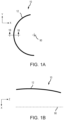
FIG. 1A illustrates a front-view profile of a stiffened panel half (such as for an aircraft nacelle fan cowl) having a semi-cylindrical geometry, in accordance with various embodiments. -
FIG. 1B illustrates a section view of the panel half ofFIG. 1A having a rounded geometry, in accordance with various embodiments. -
FIG. 2 illustrates a perspective view of a invar mold, in accordance with various embodiments -
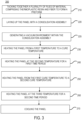
FIG. 3 provides a flow chart for a method for manufacturing a fiber-reinforced thermoplastic panel, in accordance with various embodiments. -
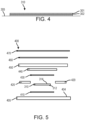
FIG. 4 illustrates a step from the method ofFIG. 3 , in accordance with various embodiments. -
FIG. 5 illustrates a step from the method ofFIG. 3 , in accordance with various embodiments. -
FIG. 6 illustrates a hot bonder system for use in the method fromFIG. 3 , in accordance with various embodiments. - The detailed description of exemplary embodiments herein refers to the accompanying drawings, which show exemplary embodiments by way of illustration. While these exemplary embodiments are described in sufficient detail to enable those skilled in the art to practice the inventions, it should be understood that other embodiments may be realized and that logical changes and adaptations in design and construction may be made in accordance with this invention and the teachings herein. Thus, the detailed description herein is presented for purposes of illustration only and not for limitation. The scope of the invention is defined by the appended claims. For example, the steps recited in any of the method or process descriptions may be executed in any order and are not necessarily limited to the order presented. Furthermore, any reference to singular includes plural embodiments, and any reference to more than one component or step may include a singular embodiment or step. Also, any reference to attached, fixed, connected or the like may include permanent, removable, temporary, partial, full and/or any other possible attachment option. Additionally, any reference to without contact (or similar phrases) may also include reduced contact or minimal contact. Surface shading lines may be used throughout the figures to denote different parts but not necessarily to denote the same or different materials. In some cases, reference coordinates may be specific to each figure.
- The thermoplastic panel manufacturing process, as described herein, may provide a relatively quick manufacturing process, e.g., approximately half of a cure duration of a typical thermoplastic panel manufacturing process, of a thermoplastic panel, such as the outer skin for a stiffened panel. The thermoplastic panel manufacturing process, as described herein, may provide an efficient, straightforward, manufacturing process for producing a flat thermoplastic panel, a contoured thermoplastic panel, or the like.
- With reference to
FIG. 1A , a stiffenedpanel half 10 is illustrated, in accordance with various embodiments. Stiffenedpanel half 10 may comprise anouter skin 12.Outer skin 12 may comprise a semi-cylindrical geometry when viewed from the aft direction, as shown in the illustrated embodiment.Outer skin 12 may define acenterline axis 90. Stated differently,outer skin 12 may be bent aroundcenterline axis 90. - With reference to
FIG. 1B , a section view of stiffenedpanel half 10 is illustrated, in accordance with various embodiments.Outer skin 12 may be contoured along the longitudinal direction (i.e., the Z-direction). Stated differently,outer skin 12 may comprise a non-linear geometry (e.g., rounded) along the longitudinal direction. -
Outer skin 12 may be made from a fiber-reinforced thermoplastic material. In various embodiments, theouter skin 12 comprises a continuous reinforcing fiber and a thermoplastic resin. The reinforcing fiber to be used for theouter skin 12 has no particular limitations with respect to the type thereof, and examples thereof include metal fibers, such as an aluminum fiber, a brass fiber, and a stainless steel fiber, carbon fibers (including graphite fibers), such as polyacrylonitrile (PAN)-based carbon fibers, rayon-based carbon fibers, lignin-based carbon fibers, and pitch-based carbon fibers, insulating fibers, such as glass fiber, organic fibers, such as aramid fibers, polyparaphenylene benzoxazole (PBO) fibers, polyphenylene sulfide fibers, polyester fibers, acrylic fibers, nylon fibers, and polyethylene fibers, and inorganic fibers, such as silicon carbide fibers and silicon nitride fibers. Fibers prepared by applying surface treatment to these fibers are also available. Examples of the surface treatment include treatment with a coupling agent, treatment with a sizing agent, treatment with a binder, and adhesion treatment with an additive in addition to deposition treatment with conductive metal. - In the disclosure, the thermoplastic resin to be used for the outer skin 110 may be either crystalline or amorphous.
- Examples of the crystalline thermoplastic resin include polyester, polyolefin, polyoxymethylene (POM), polyamide (PA), polyarylene sulfide, polyketone (PK), polyetherketone (PEK), polyether ether ketone (PEEK), polyether ketone ketone (PEKK), polyvinylidene fluoride (PVDF), polytetrafluoroethylene (PTFE), polyaryletherketone (PAEK), polyether nitrile (PEN), fluororesin, and liquid crystal polymer (LCP). Examples of the polyester include polyethylene terephthalate (PET), polybutylene terephthalate (PBT), polytrimethylene terphthalate (PTT), polyethylene naphthalate (PEN), and liquid crystal polyester. Examples of the polyolefin include polyethylene (PE), polypropylene (PP), and polybutylene. Examples of the polyarylene sulfide include polyphenylene sulfide (PPS). Examples of the fluororesin include polytetrafluoroethylene.
- Examples of the amorphous thermoplastic resin include polystyrene, polycarbonate (PC), polymethyl methacrylate (PMMA), polyvinyl chloride (PVC), polyphenylene ether (PPE), polyimide (PI), polyamide imide (PAI), polyetherimide (PEI), polysulfone (PSU), polyether sulfone (PES), and polyarylate (PAR). The thermoplastic resin to be used for the outer skin 110 also may be phenoxy resin, polystyrene, polyolefin, polyurethane, polyester, polyamide, polybutadiene, polyisoprene, fluorine resin, acrylonitrile, and other thermoplastic elastomers, and copolymers and modified resin thereof.
- Although described herein with respect to a stiffened panel and an outer skin, and a fiber-reinforced thermoplastic material, the present disclosure is not limited in this regard. For example, a thermoplastic panel, flat or countered, made of a thermoplastic material comprising only a thermoplastic resin is within the scope of this disclosure. In various embodiments, the thermoplastic material is made of a crystalline thermoplastic resin.
- With reference to
FIG. 2 , abonding tool 100 with aninvar mold 102 havinglayup surface 104 is shown, in accordance with various embodiments.Invar mold 102 may include alayup surface 104 with a contour in the shape of a part to be produced. Although illustrated as having a contoured shape, a flat shape is also within the scope of this disclosure.Supports 108 may provide support forbonding tool 100.Invar mold 102 may have asidewall 106 of thicknessT. Invar mold 102 may have a substantially uniform thickness such that the thickness ofinvar mold 102 at any point may be approximately equal to thickness T. Thickness T may be a thickness from one half inch (1.3 cm) to six inches (15.2 cm). For example, thickness T may be approximately one inch (2.5 cm). - With reference to
FIG. 3 , amethod 200 for manufacturing a thermoplastic panel is provided, in accordance with various embodiments.Method 200 includes tacking together a plurality of plies of material comprising thermoplastic resin and fiber to form a panel (step 210).Method 200 includes laying up the panel with a consolidation assembly (step 220). -
Method 200 includes generating a vacuum environment within the consolidation assembly (step 225).Method 200 includes heating the panel from a first temperature (e.g., between 0 °F (-18 °C) and 100 °F (38 °C)) to a first cure temperature (step 230). Stated another way, themethod 200 may comprise applying heat for a first time period to take the temperature from the first temperature to the first cure temperature. In various embodiments, the first cure temperature may be between 500 °F (260 °C) and 600 °F (316 °C), or approximately 545 °F (285 °C). In various embodiments a rate of temperature increase ofstep 230 may be between 10 °F (5.6 °C) and 20 °F (11.2 °C) per minute, or approximately 15 °F (8.3 °C).Method 200 includes heating the panel at the second temperature for a first time period (e.g., a first dwell period) (step 240). The first time period may be between 5 minutes and 60 minutes, or approximately 30 minutes.Method 200 includes heating the panel from the first cure temperature to a second cure temperature (step 250). The second cure temperature may be between 600 °F (316 °C) and 800 °F (427 °C), or approximately 715 °F (316 °C).Method 200 includes heating the panel at the second cure temperature for a second time period (e.g., a second dwell period) (step 260). The second time period may be between 5 minutes and 60 minutes, or approximately 30 minutes.Method 200 includes cooling the panel (step 270). Cooling the panel may be by exposing the panel to ambient conditions, or active cooling. The present disclosure is not limited in this regard. In various embodiments, steps 230 - 270 are all performed within the consolidation assembly as described further herein. In various embodiments,method 200 may be faster and less expensive relative to typical thermoplastic panel manufacturing processes, such as curing via an oven or the like. In various embodiments, themethod 200 may facilitate manufacturing of smaller thermoplastic, panels or components, that can be utilized in repairs or the like. - With combined reference to
FIG. 3 andFIG. 4 , step 210 may include stacking plies offiber sheets 301 andthermoplastic resin sheets 302 to a desired thickness to form a panel preform 310 (also referred to herein as a preform). In various embodiments, and for ease of handling, thesheets planar surface 305. In various embodiments, with brief reference toFIG. 5 , thesheets consolidation assembly 400 on aninvar mold 405. The present disclosure is not limited in this regard. In various embodiments, theresin sheets 302 may be "tacky" at a room temperature. Therefore, theresin sheets 302 may be "tacked" or stick toadjacent fiber sheets 301 without adding additional heat. However, in various embodiments, local heat may be applied to tack theresin sheets 302 andfiber sheets 301 together to form a flat sheet of material. Various methods may be used to tack together the stack of sheets to hold the sheets in place with respect to each other without departing from the scope of the present disclosure, such as clamping and ultrasonic welding, among others. Furthermore, any number of plies offiber sheets 301 and/orresin sheets 302 may be used depending on the desired thickness of the fiber-reinforced thermoplastic panel. Furthermore, the thickness of the panel may vary. In this regard, a first location of the panel may have a first number of plies and a second location of the panel may have a second number of plies, different from the first number of plies. After thepanel preform 310 has been formed, thepanel preform 310 may be laid up on a consolidation assembly 400 (seeFIG. 5 ). - With combined reference to
FIG. 3 andFIG. 5 , step 220 may include laying up thepanel preform 310 to form a consolidation assembly 400 (step 220). In this manner, theconsolidation assembly 400 includes aninvar mold 405. In various embodiments, theinvar mold 405 may be in accordance with theinvar mold 102 fromFIG. 1 . In various embodiments, theinvar mold 405 may be substantially flat. "Substantially flat" as referred to herein includes a flatness (e.g,. a variance from a reference plane) of less than 0.10 inches (0.25 cm), or less than 0.05 inches (0.13 cm), or less than 0.01 inches (0.025 cm). For the sake of brevity, themethod 200 and stack up of theconsolidation assembly 400 described herein will be described with respect to a square panel. However, the present disclosure is no way limited in this regard. - The
consolidation assembly 400 may further comprise a release agent 410 (e.g., a solvent-based moisture-curing release epoxy such as that sold under the mark LOCTITE® Frekote 700NC). Therelease agent 410 may be disposed directly on thelayup surface 404, followed by thepanel preform 310. Therelease agent 410 may define a cross-sectional area that is greater than a cross sectional area of thepanel preform 310 in the stack up. For example, if thepanel preform 310 is a 12 inch (30.5 cm) x 12 inch (30.5 cm) panel, therelease agent 410 may cover a cross-sectional area of approximately 14 inches (36 cm) x 14 inches (36 cm), in accordance with various embodiments. In this regard, an entire mating surface of thepanel preform 310 may be in contact with therelease agent 410, in accordance with various embodiments. For a contoured shape, the cross-sectional area referred to herein is through a cross-section along a plane defined through a thickness of a respective component. Stated another way, the cross-sectional area is a surface area of a mating surface, in accordance with various embodiments. - The
consolidation assembly 400 further comprises an ultra-high temperature (UHT)breather frame 420. TheUHT breather frame 420 may enclose a perimeter of the panel preform 310 (e.g., thebreather frame 420 may be disposed about an entirety of a perimeter of the panel preform 310). For example, if thepanel preform 310 is a 12-inch (30.5 cm) x 12-inch (30.5 cm) panel, theUHT breather frame 420 may define an opening with an cross-sectional area of approximately 14 inches (36 cm) x 14 inches (36 cm). In various embodiments, the opening defined by theUHT breather frame 420 may be approximately equal to the cross-sectional area of therelease agent 410. The present disclosure is not limited in this regard. - The
UHT breather frame 420 may be any UHT breather frame, such as a non-woven blended, fiberglass breather sold under the trademark Airweave® which can be purchased from Airtech International, Inc. located in Huntington Beach CA. TheUHT breather frame 420 may facilitate release of trapped air during the consolidation process defined in steps 230-270 frommethod 200. In various embodiments, theUHT breather frame 420 provides efficient breathing during themethod 200 fromFIG. 3 for temperatures up to and including 800 °F (430 °C). - In various embodiments, the
consolidation assembly 400 further comprises arelease film 430. Duringstep 220 ofmethod 200, therelease film 430 is applied to amating surface 314 of thepanel preform 310. Themating surface 314 may be opposite amating surface 312 in contact with therelease agent 410. Thus, thepanel preform 310 is disposed between (i.e., in a thickness direction) therelease agent 410 and therelease film 430. In various embodiments, therelease agent 410 and therelease film 430 may comprise the same material. In various embodiments, therelease agent 410 and therelease film 430 may be different materials. For example, therelease film 430 may comprise a high-performance polymeric material, such as a polyimide material (e.g., sold under the name Thermalide RCBS which can be purchased from Airtech International, Inc. located in Huntington Beach CA). - In various embodiments, the
consolidation assembly 400 further comprises acaul plate 440 disposed on top of therelease film 430. In this regard,caul plate 440 and theinvar mold 405 sandwich thepanel preform 310 therebetween withrelease film 430 andrelease agent 410 preventing any contact between theinvar mold 405 or thecaul plate 440 and thepanel preform 310, thus promoting an efficient consolidation process as outlined in steps 230-270 ofmethod 200. - The
consolidation assembly 400 further comprises aheated blanket 450. As described further herein, theheated blanket 450 may be coupled to a hot bond unit. Theheated blanket 450 may supply the heat during consolidation as defined in steps 230-270 ofmethod 200. The hot bond unit (e.g.,hot bond unit 602 fromFIG. 6 ) may be configured to heat up theheated blanket 450 and supply a vacuum within theconsolidation assembly 400 as described further herein. - The
consolidation assembly 400 further comprises avacuum bag 470 including a high temperature vacuum bagging material (e.g., polyimide bagging film, nylon bagging film, polyethylene bagging film, elastomeric bagging film, etc.). The consolidation assembly further comprises aUHT breather 460 disposed between theheated blanket 450 and avacuum bag 470. In various embodiments, the vacuum bagging material and theinvar mold 405 fully encloses the remaining components of theconsolidation assembly 400. In this regard, thevacuum bag 470 is configured to facilitate a vacuum environment within theconsolidation assembly 400 during steps 230-270 ofmethod 200 as described further herein. - Referring now to
FIG. 6 , ahot bonder system 600 for use with theconsolidation assembly 400 is illustrated, in accordance with various embodiments. Thehot bonder system 600 comprises ahot bond unit 602 in electrical communication with the heated blanket 450 (e.g., via thermocouples 612) and in fluid communication with thevacuum bag 470. Thehot bond unit 602 is configured to heat theheated blanket 450 via thethermocouples 612 from power supplied by thepower source 604. Additionally, thehot bond unit 602 is configured to create a vacuum environment within thevacuum bag 470 of theconsolidation assembly 400 fromFIG. 5 viacompressed air source 604 creating a vacuum in thevacuum fluid line 614. - Benefits, other advantages, and solutions to problems have been described herein with regard to specific embodiments. Furthermore, the connecting lines shown in the various figures contained herein are intended to represent exemplary functional relationships and/or physical couplings between the various elements. It should be noted that many alternative or additional functional relationships or physical connections may be present in a practical system. However, the benefits, advantages, solutions to problems, and any elements that may cause any benefit, advantage, or solution to occur or become more pronounced are not to be construed as critical, required, or essential features or elements of the inventions. The scope of the inventions is accordingly to be limited by nothing other than the appended claims, in which reference to an element in the singular is not intended to mean "one and only one" unless explicitly so stated, but rather "one or more." Moreover, where a phrase similar to "at least one of A, B, or C" is used in the claims, it is intended that the phrase be interpreted to mean that A alone may be present in an embodiment, B alone may be present in an embodiment, C alone may be present in an embodiment, or that any combination of the elements A, B and C may be present in a single embodiment; for example, A and B, A and C, B and C, or A and B and C. Different cross-hatching is used throughout the figures to denote different parts but not necessarily to denote the same or different materials.
- Systems, methods and apparatus are provided herein. In the detailed description herein, references to "one embodiment," "an embodiment," "an example embodiment," etc., indicate that the embodiment described may include a particular feature, structure, or characteristic, but every embodiment may not necessarily include the particular feature, structure, or characteristic. Moreover, such phrases are not necessarily referring to the same embodiment. Further, when a particular feature, structure, or characteristic is described in connection with an embodiment, it is submitted that it is within the knowledge of one skilled in the art to affect such feature, structure, or characteristic in connection with other embodiments whether or not explicitly described. After reading the description, it will be apparent to one skilled in the relevant art(s) how to implement the disclosure in alternative embodiments.
- Furthermore, no element, component, or method step in the present disclosure is intended to be dedicated to the public regardless of whether the element, component, or method step is explicitly recited in the claims. As used herein, the terms "comprises," "comprising," or any other variation thereof, are intended to cover a non-exclusive inclusion, such that a process, method, article, or apparatus that comprises a list of elements does not include only those elements but may include other elements not expressly listed or inherent to such process, method, article, or apparatus.
Claims (15)
- A method of manufacturing a thermoplastic panel, the method comprising:tacking together a plurality of plies of material comprising thermoplastic resin and fiber to form a preform;laying up the preform on a layup surface (104; 404) of an invar mold (102; 405);at least partially enclosing the preform within a breather frame (420);laying up a caul plate (440), the preform disposed between the caul plate (440) and the invar mold (102; 405);laying up a heated blanket (450) on the caul plate (440);enclosing the preform within a vacuum bag (470) and the invar mold (102; 405);generating a vacuum environment between the invar mold (102; 405) and the vacuum bag (470); andheating the heated blanket (450) to a first cure temperature.
- The method of manufacturing of claim 1, wherein the vacuum environment is generated from a hot bonder system (600).
- The method of manufacturing of claim 2, wherein the heated blanket (450) is heated via the hot bonder system (600).
- The method of manufacturing of any preceding claim, further comprising laying up a release agent (410) on the layup surface (104; 404) of the invar mold (102; 405) prior to laying up the preform on the layup surface (104; 404) of the invar mold (102; 405).
- The method of manufacturing of claim 4, further comprising laying up a release film (430) on a mating surface (314) of the preform, the mating surface (314) opposite a second mating surface (312) in contact with the release agent (410).
- The method of any preceding claim, further comprising laying up a breather bag on the heated blanket (450) prior to enclosing the preform within the vacuum bag (470) and the invar mold (102; 405).
- The method of any preceding claim, further comprising forming the thermoplastic panel in response to heating the thermoplastic panel.
- The method of any preceding claim, further comprising cooling the thermoplastic panel.
- A method of manufacturing a thermoplastic panel, the method comprising:laying up a panel preform (310) within a consolidation assembly (400), the panel preform (310) comprising a plurality of plies of material comprising thermoplastic resin and fiber;generating, via a hot bond unit (602), a vacuum environment within the consolidation assembly (400); andheating, via the hot bond unit (602) and through a heated blanket (450) within the consolidation assembly (400), the panel preform (310), wherein the heating optionally further comprises heating from a first temperature to a first cure temperature.
- The method of manufacturing of claim 9, wherein the consolidation assembly (400) comprises an invar mold (102; 405) and a caul plate (440), the panel preform (310) disposed between the invar mold (102; 405) and the caul plate (440).
- The method of manufacturing of claims 9 or 10, wherein the consolidation assembly (400) comprises an ultra-high temperature (UHT) breather frame (420), the panel preform (310) disposed within an opening of the UHT breather frame (420).
- The method of manufacturing of claims 10 or 11, wherein the consolidation assembly (400) comprises a release agent (410) disposed between a first mating surface (314; 312) of the panel preform (310) and a layup surface (104; 404) of the invar mold (102; 405) and wherein the consolidation assembly (400) optionaly comprises a release film (430) disposed between a second mating surface (314) of the panel preform (310) and the caul plate (440), the second mating surface (314) opposite the first mating surface (312).
- The method of manufacturing of any of claims 9 to 12, wherein a rate of heating from the first temperature to the first cure temperature is between 10 °F (5.6 °C) and 20 °F (11.2 °C) per minute, and wherein the first cure temperature is between 500 °F (260 °C) and 600 °F (316 °C).
- The method of manufacturing of any of claims 9 to 13, wherein the heating further comprises heating from the first cure temperature to a second cure temperature, for example between 600 °F (316 °C) and 800 °F (427 °C), after a first time period, and wherein the first time period is optionally between 5 minutes and 60 minutes.
- A method of manufacturing a thermoplastic panel, the method comprising:placing a panel preform (310) comprising a plurality of plies of material comprising thermoplastic resin and fiber under a vacuum environment;heating, via a hot bond system, the panel preform (310) from a first temperature to a first cure temperature at a first rate, the first rate being between 10 °F (5.6 °C) and 20 °F (11.2 °C) per minute; andheating, via the hot bond system, the panel preform (310) at the first cure temperature, the first cure temperature being between 500 °F (260 °C) and 800 °F (427 °C), for example between 500 °F (260 °C) and 600 °F (316 °C),wherein the method optionally further comprises:heating, via the hot bond system, the panel preform (310) from the first cure temperature to a second cure temperature between 600 °F (316 °C) and 800 °F (427 °C); andcooling the panel preform (310).
Applications Claiming Priority (1)
| Application Number | Priority Date | Filing Date | Title |
|---|---|---|---|
| US17/554,775 US12011887B2 (en) | 2021-12-17 | 2021-12-17 | Systems and methods for thermoplastic panel manufacturing |
Publications (2)
| Publication Number | Publication Date |
|---|---|
| EP4197757A2 true EP4197757A2 (en) | 2023-06-21 |
| EP4197757A3 EP4197757A3 (en) | 2023-10-25 |
Family
ID=84487534
Family Applications (1)
| Application Number | Title | Priority Date | Filing Date |
|---|---|---|---|
| EP22212650.0A Pending EP4197757A3 (en) | 2021-12-17 | 2022-12-09 | Systems and methods for themoplastic panel manufacturing |
Country Status (2)
| Country | Link |
|---|---|
| US (1) | US12011887B2 (en) |
| EP (1) | EP4197757A3 (en) |
Family Cites Families (15)
| Publication number | Priority date | Publication date | Assignee | Title |
|---|---|---|---|---|
| US4765942A (en) | 1986-09-30 | 1988-08-23 | The Boeing Company | Method of consolidating thermoplastic poly(amide-imide) components |
| US5236646A (en) * | 1991-02-28 | 1993-08-17 | The United States Of America As Represented By The Secretary Of The Navy | Process for preparing thermoplastic composites |
| US5968445A (en) | 1998-01-05 | 1999-10-19 | The Boeing Company | Method and apparatus for curing large composite panels |
| US6761783B2 (en) | 2002-04-09 | 2004-07-13 | The Boeing Company | Process method to repair bismaleimide (BMI) composite structures |
| DE102004062064B4 (en) * | 2004-12-23 | 2008-07-17 | Röder Präzision GmbH | Process for producing and repairing composite fiber composite metal components and apparatus for carrying out the method |
| US20090165945A1 (en) * | 2007-12-27 | 2009-07-02 | General Electric Company | Tool for use in the manufacture of turbine bucket shroud and related method |
| US20130143006A1 (en) | 2011-12-02 | 2013-06-06 | The Boeing Company | Reducing Porosity in Composite Structures |
| US9243407B2 (en) | 2013-04-25 | 2016-01-26 | Sikorsky Aircraft Corporation | Structure repair with polymer matrix composites |
| WO2014195799A2 (en) * | 2013-06-07 | 2014-12-11 | Toray Industries, Inc. | Fiber reinforced polymer composition enabling rapid-cycle void-free composite manufacturing |
| JP6463094B2 (en) | 2014-11-25 | 2019-01-30 | 三菱重工業株式会社 | Joining apparatus and joining method |
| US10589477B2 (en) | 2016-05-02 | 2020-03-17 | GM Global Technology Operations LLC | Cosmetic repair of a thermoplastic carbon fiber composite |
| US10239300B2 (en) | 2016-07-12 | 2019-03-26 | Rohr, Inc. | Sandwich panel disbond repair |
| US10309695B2 (en) | 2016-08-09 | 2019-06-04 | The Boeing Company | Methods and apparatuses for maintaining temperature differential in materials using thermoelectric devices during hot bonded repair |
| FR3102705B1 (en) | 2019-10-30 | 2021-10-22 | Stelia Aerospace | Thermoplastic parts manufacturing system |
| US11529777B2 (en) | 2020-02-05 | 2022-12-20 | The Boeing Company | Hot bond repair of structures using unmanned aerial vehicles |
-
2021
- 2021-12-17 US US17/554,775 patent/US12011887B2/en active Active
-
2022
- 2022-12-09 EP EP22212650.0A patent/EP4197757A3/en active Pending
Also Published As
| Publication number | Publication date |
|---|---|
| US12011887B2 (en) | 2024-06-18 |
| EP4197757A3 (en) | 2023-10-25 |
| US20230191722A1 (en) | 2023-06-22 |
Similar Documents
| Publication | Publication Date | Title |
|---|---|---|
| EP3858585B1 (en) | Systems and methods for thermoplastic panel stretch/roll forming | |
| US11926110B2 (en) | Thermoplastic composite panel systems and methods | |
| US10071506B2 (en) | System for facilitating fluid movement in closed molds | |
| US20200238576A1 (en) | Heating blanket and method for use | |
| JP6273804B2 (en) | Manufacturing method of fiber reinforced plastic molding | |
| US9649809B2 (en) | Wrinkle diffuser system for composites | |
| WO2015115433A1 (en) | Frp-molding jig and method for molding frp structure | |
| CN113226722A (en) | Method and system for welding thermoplastic composite structural members | |
| US10807325B2 (en) | Methods for combining components of varying stages of cure | |
| JP6216792B2 (en) | Method for forming tubes from thermoplastic sandwich sheets | |
| EP4209333A2 (en) | Ply tacking devices, systems, and methods | |
| EP4197757A2 (en) | Systems and methods for themoplastic panel manufacturing | |
| EP3392027B1 (en) | Systems and methods for assembling elongate composite structures | |
| US6612523B2 (en) | Aircraft structures having improved through-thickness thermal conductivity | |
| EP3815878B1 (en) | Systems and methods for thermoforming thermoplastic structures | |
| US12043003B2 (en) | Assemblies and methods for forming fiber reinforced thermoplastic structures | |
| US11993388B2 (en) | Corrugated stiffening devices utilizing peaks and valleys and methods of manufacture | |
| US11338497B2 (en) | Systems and methods for thermoforming thermoplastic structures | |
| US11780179B2 (en) | Thermoplastic composite panel with corrugated peaks and troughs stiffening systems and methods | |
| EP4385699A1 (en) | Pi-shaped preform and bonded joints thereof | |
| US20230182412A1 (en) | Pliable structures and associated methods and systems for replicating a contour of a surface |
Legal Events
| Date | Code | Title | Description |
|---|---|---|---|
| PUAI | Public reference made under article 153(3) epc to a published international application that has entered the european phase |
Free format text: ORIGINAL CODE: 0009012 |
|
| STAA | Information on the status of an ep patent application or granted ep patent |
Free format text: STATUS: THE APPLICATION HAS BEEN PUBLISHED |
|
| AK | Designated contracting states |
Kind code of ref document: A2 Designated state(s): AL AT BE BG CH CY CZ DE DK EE ES FI FR GB GR HR HU IE IS IT LI LT LU LV MC ME MK MT NL NO PL PT RO RS SE SI SK SM TR |
|
| PUAL | Search report despatched |
Free format text: ORIGINAL CODE: 0009013 |
|
| AK | Designated contracting states |
Kind code of ref document: A3 Designated state(s): AL AT BE BG CH CY CZ DE DK EE ES FI FR GB GR HR HU IE IS IT LI LT LU LV MC ME MK MT NL NO PL PT RO RS SE SI SK SM TR |
|
| RIC1 | Information provided on ipc code assigned before grant |
Ipc: B29C 70/30 20060101ALI20230915BHEP Ipc: B29C 70/00 20060101ALI20230915BHEP Ipc: B29D 99/00 20100101ALI20230915BHEP Ipc: B29C 70/44 20060101AFI20230915BHEP |
|
| STAA | Information on the status of an ep patent application or granted ep patent |
Free format text: STATUS: REQUEST FOR EXAMINATION WAS MADE |
|
| 17P | Request for examination filed |
Effective date: 20240425 |
|
| RBV | Designated contracting states (corrected) |
Designated state(s): AL AT BE BG CH CY CZ DE DK EE ES FI FR GB GR HR HU IE IS IT LI LT LU LV MC ME MK MT NL NO PL PT RO RS SE SI SK SM TR |