EP4197725A1 - Razor connector - Google Patents
Razor connector Download PDFInfo
- Publication number
- EP4197725A1 EP4197725A1 EP21215575.8A EP21215575A EP4197725A1 EP 4197725 A1 EP4197725 A1 EP 4197725A1 EP 21215575 A EP21215575 A EP 21215575A EP 4197725 A1 EP4197725 A1 EP 4197725A1
- Authority
- EP
- European Patent Office
- Prior art keywords
- razor
- connector
- cartridge
- flap
- razor connector
- Prior art date
- Legal status (The legal status is an assumption and is not a legal conclusion. Google has not performed a legal analysis and makes no representation as to the accuracy of the status listed.)
- Granted
Links
Images




Classifications
-
- B—PERFORMING OPERATIONS; TRANSPORTING
- B26—HAND CUTTING TOOLS; CUTTING; SEVERING
- B26B—HAND-HELD CUTTING TOOLS NOT OTHERWISE PROVIDED FOR
- B26B21/00—Razors of the open or knife type; Safety razors or other shaving implements of the planing type; Hair-trimming devices involving a razor-blade; Equipment therefor
- B26B21/40—Details or accessories
- B26B21/52—Handles, e.g. tiltable, flexible
- B26B21/521—Connection details, e.g. connection to razor heads
-
- B—PERFORMING OPERATIONS; TRANSPORTING
- B26—HAND CUTTING TOOLS; CUTTING; SEVERING
- B26B—HAND-HELD CUTTING TOOLS NOT OTHERWISE PROVIDED FOR
- B26B21/00—Razors of the open or knife type; Safety razors or other shaving implements of the planing type; Hair-trimming devices involving a razor-blade; Equipment therefor
- B26B21/08—Razors of the open or knife type; Safety razors or other shaving implements of the planing type; Hair-trimming devices involving a razor-blade; Equipment therefor involving changeable blades
- B26B21/14—Safety razors with one or more blades arranged transversely to the handle
- B26B21/22—Safety razors with one or more blades arranged transversely to the handle involving several blades to be used simultaneously
- B26B21/222—Safety razors with one or more blades arranged transversely to the handle involving several blades to be used simultaneously with the blades moulded into, or attached to, a changeable unit
- B26B21/225—Safety razors with one or more blades arranged transversely to the handle involving several blades to be used simultaneously with the blades moulded into, or attached to, a changeable unit the changeable unit being resiliently mounted on the handle
-
- B—PERFORMING OPERATIONS; TRANSPORTING
- B26—HAND CUTTING TOOLS; CUTTING; SEVERING
- B26B—HAND-HELD CUTTING TOOLS NOT OTHERWISE PROVIDED FOR
- B26B21/00—Razors of the open or knife type; Safety razors or other shaving implements of the planing type; Hair-trimming devices involving a razor-blade; Equipment therefor
- B26B21/40—Details or accessories
- B26B21/4068—Mounting devices; Manufacture of razors or cartridges
- B26B21/4075—Mounting devices
-
- B—PERFORMING OPERATIONS; TRANSPORTING
- B26—HAND CUTTING TOOLS; CUTTING; SEVERING
- B26B—HAND-HELD CUTTING TOOLS NOT OTHERWISE PROVIDED FOR
- B26B21/00—Razors of the open or knife type; Safety razors or other shaving implements of the planing type; Hair-trimming devices involving a razor-blade; Equipment therefor
- B26B21/40—Details or accessories
- B26B21/52—Handles, e.g. tiltable, flexible
- B26B21/528—Manufacture of razor handles
-
- B—PERFORMING OPERATIONS; TRANSPORTING
- B33—ADDITIVE MANUFACTURING TECHNOLOGY
- B33Y—ADDITIVE MANUFACTURING, i.e. MANUFACTURING OF THREE-DIMENSIONAL [3D] OBJECTS BY ADDITIVE DEPOSITION, ADDITIVE AGGLOMERATION OR ADDITIVE LAYERING, e.g. BY 3D PRINTING, STEREOLITHOGRAPHY OR SELECTIVE LASER SINTERING
- B33Y80/00—Products made by additive manufacturing
Definitions
- the present disclosure relates to the field of razors. More specifically, the present disclosure relates to razor connectors which attach a razor cartridge to a razor handle.
- Razors are well known everyday items to shave of unwanted bodily hair, e.g. beard hairs.
- the razor may comprise a razor cartridge including blades configured to cut the hair and a razor handle used attached thereto.
- a user holds the razor handle and brings the razor cartridge into contact with a portion of skin.
- the razor cartridge moves in a shaving direction and unwanted hair is removed.
- the razor cartridge may be releasably connected to the razor handle via a razor connector.
- a releasable attachment of the razor cartridge may allow exchanging the razor cartridge, for example when the blades have become dull, instead of discarding the entire razor.
- razor connectors typically comprise complex mechanisms requiring multiple components, for example springs, pushers, push buttons, releasing mechanisms etc. The complex mechanisms increase the assembly complexity and increase the production time. Further, the multiple components, especially those that are movable, increase the risk of system failure as they are more prone to breaking.
- the present disclosure aims to address the aforementioned issues in optimizing razor connectors.
- the present disclosure relates to a razor connector 10 configured to connect a razor cartridge 100 to a razor handle 12.
- the razor connector comprises a tongue, configured to allow pivotable movement of the razor cartridge 100 relative to the razor handle 12 and at least one interlocking feature configured to interlock with at least one interlocking part of the razor cartridge 100.
- the razor connector comprises at least one flap 16 configured to disconnect the razor cartridge 100 from the razor connector 10 upon actuation.
- the tongue may be a flexible tongue 14.
- the at least one interlocking feature may be a recess 18, in particular a recess 18 configured to interlock with at least one protrusion of the razor cartridge 100.
- the at least one interlocking feature may be an interlocking protrusion, in particular an interlocking protrusion configured to interlock with at least one recess of the razor cartridge 100
- the flap 16 may be integrally formed with the interlocking feature.
- the flap 16 may be integrally formed with the tongue.
- the flap 16, the interlocking feature and the tongue may be integrally formed.
- the razor connector 10 may be a one-piece part.
- the razor connector 10 may comprise a plurality of layers, in particular a plurality of layers substantially parallel to each other.
- the at least one flap 16 may be configured to release the at least one interlocking part of the razor cartridge 100 from the at least one interlocking feature when actuated.
- the at least one flap 16 may comprise at least one protrusion 20, in particular at least one protrusion 20 extending towards the razor cartridge 100 when the razor cartridge 100 is connected to the razor connector 10.
- the at least one protrusion 20 may be configured to disconnect the razor cartridge 100 from the razor connector 10 upon actuation of the at least one flap 16 by pushing the interlocking part of the razor cartridge 100 out of the interlocking feature, in particular wherein the at least one protrusion 20 is configured to disconnect the razor cartridge 100 from the razor connector 10 upon actuation of the at least one flap 16 by pushing the razor cartridge's 100 protrusion of out of the razor connector's 10 recess 18.
- the at least one protrusion 20 may be configured to preload the razor cartridge 100 when the razor cartridge 100 is connected to the razor connector 10.
- the at least one flap 16 may be preloaded when the razor cartridge 100 is connected to the razor cartridge 100.
- the razor connector 10 may comprise two flaps 16 opposing one another.
- the razor connector 10 may comprise a receiving head 22 configured to receive a connector sleeve 102 of the razor cartridge 100.
- the razor connector 10 may be integrally formed with the razor handle 12.
- the tongue may extend from a distal end of the razor connector 10 and wherein the razor connector 10 is connected to the razor handle 12 at a proximal end and wherein the distal end and proximal end define a proximal-distal razor connector axis 24.
- the at least one flap 16 may be arranged in proximal direction of the receiving head's 22 distal end.
- the at least one protrusion 20 may be arranged at the distal end of the at least one flap 16.
- the at least one flap 16 may comprise at least one actuation surface 26 configured to be actuated by a user to release the razor cartridge 100.
- the at least one actuation surface 26 may be disposed substantially parallel to the proximal-distal razor connector axis 24.
- the at least one actuation surface 26 faces away from the proximal-distal razor connector axis 24.
- the at least one actuation surface 26 may comprise an indicator, more specifically a haptic indicator and in particular a protrusion, a dot, a cavity, a groove and/or a rubber element.
- the at least one flap 16 may be moved away from the proximal-distal razor connector axis 24 when preloaded.
- moving the at least one flap 16 towards the proximal-distal razor connector axis 24 may disconnect the razor cartridge 100 from the razor connector 10.
- the razor connector 10 may have a top side 32 and bottom side 36.
- the tongue may comprise a first section extending parallel to the proximal-distal razor connector axis 24 along the bottom side of the razor connector 10 and a second section diverging towards the top side 32 of the razor connector 10.
- the tongue may have a polygonal cross-section, more specifically a square, rectangular or octagonal shape and in particular a rectangular shape.
- a corner of the polygonal cross-section may be round.
- the at least one protrusion 20 may be placed at the top side 32 of the razor connector 10.
- the interlocking feature may be positioned proximally of the receiving head's 22 distal end, more specifically on the bottom side of the razor connector 10 on the receiving head 22 proximally of the receiving head's 22 distal end and in particular on the bottom side of the razor connector 10 on the receiving head 22 proximally of the receiving head's 22 distal end adjacent to the tongue.
- a layer of the plurality of layers may have a thickness between about 5 ⁇ m to about 100 ⁇ m, more specifically between about 10 ⁇ m to about 50 ⁇ m and in particular between about 15 ⁇ m to about 30 ⁇ m.
- a layer of the plurality of layers may have a thickness between about 0.05 mm to about 0.6 mm, more specifically between about 0.1 ⁇ m to about 0.4 mm and in particular between about 0.15 mm to about 0.3 mm.
- the razor connector 10 may comprise a first polymer, in particular a photopolymer.
- the razor connector 10 may comprise a second polymer, in particular an ABS-like polymer and/or polypropylene-like polymer.
- the razor connector 10 may comprise a third polymer, more specifically a thermoplastic polymer and in particular ABS and/or polypropylene.
- the razor connector 10 may comprise a fourth polymer, more specifically a thermoplastic elastomer and in particular a TPA, a TPC, a TPO, a TPS, a TPV, a TPZ and/or a TPU.
- a fourth polymer more specifically a thermoplastic elastomer and in particular a TPA, a TPC, a TPO, a TPS, a TPV, a TPZ and/or a TPU.
- the at least one flap 16 may be connected to the receiving head 22 at a connection shoulder 28, wherein the connection shoulder 28 comprises the second and/or fourth polymer.
- the flexible tongue 14 may comprise the second and/or fourth polymer.
- the at least one flap 16 may comprise the first and/or third polymer.
- the at least one protrusion 20 may comprise the first and/or third polymer.
- the tongue may be connected to a spring, more specifically a spring configured to allow the tongue to move along the proximal-distal razor connector axis 24 and in particular a spring that compresses and stretches along the proximal-distal razor connector axis 24.
- the present disclosure relates to a razor system comprising a razor connector 10 according to any preceding embodiment and a razor cartridge 100, wherein the razor cartridge 100 is releasably attached to the razor connector 10.
- the razor system may further comprise a razor handle 12 connected to the razor connector 10.
- the present disclosure relates to a process for manufacturing a razor connector 10 according to any preceding embodiment comprising additive manufacturing, material jetting, fused filament fabrication, stereolithography and/or selective laser sintering.
- Razor connectors typically comprise multiple components, in particular multiple movable components.
- the number of components increases the required assembly time during production, as well as the risk of breaking of the razor connector.
- the present disclosure relates to a razor connector 10 configured to connect a razor cartridge 100 to a razor handle 12.
- the razor connector comprises a tongue, configured to allow pivotable movement of the razor cartridge 100 relative to the razor handle 12 and at least one interlocking feature configured to interlock with at least one interlocking part of the razor cartridge 100.
- the razor connector comprises at least one flap 16 configured to disconnect the razor cartridge 100 from the razor connector 10 upon actuation.
- FIG. 1 illustrates an isometric view of an exemplary razor connector 10 according to the present disclosure with a razor handle 12.
- the razor connector 10 may be an individual part and connected to the razor handle 12 by a detachable or non-detachable connection, for example a push-in connection.
- Manufacturing the razor connector 10 as an individual part may be advantageous if the razor handle 12 can be rapidly and efficiently manufactured, e.g. by injection molding, whereas the razor connector 10 can only be manufactured with more cost and time intensive processes, e.g. additive manufacturing.
- an individually manufactured razor handle 12 and razor connector 10 may reduce the manufacturing time and cost of the complete razor.
- a releasably attached individually formed razor connector 10 could be exchanged if it is worn out, while retaining the razor handle 12.
- the razor connector 10 and the razor handle 12 may be integrally formed, which may reduce the assembly time even further.
- Figure 2 is a close-up top side view of the exemplary razor connector 10 of Figure 1 .
- Figure 2 shows a proximal-distal razor connector axis 24 running centrically through the razor connector 10.
- the tongue 14 may extend from a distal end of the razor connector 10.
- the razor connector 10 may be connected to the razor handle 12 at a proximal end (not illustrated, see Figure 1 ). The distal end and proximal end may define the proximal-distal razor connector axis 24.
- Figure 2 further shows two flaps 16 of the exemplary razor connector 10 being attached to the razor connector 10 towards their distal end.
- the razor connector may comprise one flap 16.
- the flap 16 may comprise a proximal 40 and a distal section 42, wherein upon actuation the distal section 42 is configured to move towards the distal end of the razor connector 10.
- the proximal section 40 of the flaps there is a gap between the flaps and the razor connector 10 allowing the proximal section 40 of the flaps 16 to be pushed towards the proximal-distal razor connector axis 24.
- the flap's 16 distal section 42 may move towards the proximal-distal razor connector axis 24 when the flap 16, in particular the flap's proximal section 40, is pushed towards the proximal-distal razor connector axis 24. Pushing the flap 16, in particular the flap's proximal section 40, towards the proximal-distal razor connector axis 24 may be considered an actuation.
- the at least one flap 16 may be shell-shaped, e.g. comprise a wall section forming a cavity, in particular an open cavity.
- the flap 16 may be rigid, more specifically the at least one flap may have a Shore D hardness between about 50 to about 120, more specifically between about 55 to about 100 and in particular between about 60 to about 90, measured according to ISO 868:2003.
- the at least one flap 16 may have an elongation at break between about 0.5 % to about 60 %, more specifically between about 1.0 % to about 25 % and in particular between about 1.8 % to about 15 %, measured according to ISO 527-1:2019.
- the at least one interlocking feature may be a recess 18, in particular a recess 18 configured to interlock with at least one protrusion of the razor cartridge 100.
- the at least one interlocking feature may be an interlocking protrusion, in particular an interlocking protrusion configured to interlock with at least one recess of the razor cartridge 100.
- the interlocking protrusion and the recess may interlock through a snap-fit when the razor connector 10 is connected to a razor cartridge 100 on its distal end.
- the razor connector 10 or parts thereof and/or the razor connector or parts thereof may be flexible, improving the snap fit and allowing release of the snap-fit.
- the distal section(s) may move in distal direction and push the razor cartridge towards the distal end.
- the at least one flap 16 may be configured to release the at least one interlocking part of the razor cartridge 100 from the at least one interlocking feature when actuated. In embodiments, the at least one flap 16 may be configured to disconnect the razor cartridge 100 from the razor connector 10 upon actuation of the at least one flap 16 by pushing the interlocking part of the razor cartridge 100 out of the interlocking feature, in particular wherein the at least one flap 16 is configured to disconnect the razor cartridge 100 from the razor connector 10 upon actuation of the at least one flap 16 by pushing the razor cartridge's 100 protrusion of out of the razor connector's 10 recess 18.
- Pushing the interlocking part of the razor cartridge 100 out of the interlocking feature of the razor connector 10 shall not be construed as requiring the protrusion 20 to directly contact the interlocking feature or part.
- the protrusion may merely push against another part of the razor cartridge 100, whereby the razor cartridge 100 moves in distal direction, which in turn may lead to the push out.
- the at least one flap 16 may comprise at least one protrusion 20.
- the at least one flap 16 may be integrally formed with at least one protrusion 20.
- the at least one protrusion 20 may improve the disconnection mechanism of the razor connector 10.
- the at least one protrusion 20 may extend towards the razor cartridge 100 when the razor cartridge 100 is connected to the razor connector 10.
- the at least one protrusion 20 may be arranged at the distal section 42 of the at least one flap 16.
- the at least one protrusion 20 at the distal section 42 of the flap 16 may increase the length of movement performed by the flap's 16 distal section, which may in turn push the connected razor cartridge 100 further away from the razor connector 10.
- the at least one protrusion 20 may be configured to disconnect the razor cartridge 100 from the razor connector 10 upon actuation of the at least one flap 16 by pushing the interlocking part of the razor cartridge 100 out of the interlocking feature, in particular wherein the at least one protrusion 20 is configured to disconnect the razor cartridge 100 from the razor connector 10 upon actuation of the at least one flap 16 by pushing the razor cartridge's 100 protrusion of out of the razor connector's 10 recess 18.
- the at least one flap 16 may be moved away from the proximal-distal razor connector axis 24 when preloaded.
- the at least one flap 16 moving away from the proximal-distal razor connector axis 24 may increase the distance the flap's 16 proximal section 40 needs to move for the actuation, which may reduce the risk of accidental actuation.
- moving the at least one flap 16 towards the proximal-distal razor connector axis 24 may disconnect the razor cartridge 100 from the razor connector 10.
- pushing the at least one flap's 16 proximal section 40 towards the proximal-distal razor connector axis 24 may disconnect the razor cartridge 100 from the razor connector 10.
- a disconnected razor cartridge 100 is shown in Figure 7 and a connected razor cartridge 100 is shown in Figure 8 .
- the at least one flap 16 may comprise at least one actuation surface 26 configured to be actuated by a user to release the razor cartridge 100.
- the actuation surface 26 may facilitate the actuation by the user.
- the actuation surface 26 may be ergonomically shaped and/or comprise a region of higher friction and/or tack e.g. by including a rubber, to improve the handling by the user.
- the at least one actuation surface 26 may be disposed substantially parallel or parallel to the proximal-distal razor connector axis 24. Arranging the at least one actuation surface 26 substantially parallel or parallel to the proximal-distal razor connector axis 24 may reduce the risk of accidental actuation. For example, if the at least one actuation surface 26 were arranged orthogonally to the proximal-distal razor connector axis 24, the actuation surface 26 may be actuated accidentally when pressed against the user's skin during the shaving action.
- Figure 3 further depicts, that in embodiments, the at least one actuation surface 26 faces away from the proximal-distal razor connector axis 24.
- the at least one actuation surface 26 faces away from the proximal-distal razor connector axis 24 may be easier to actuate by the user, as no other part may block the access.
- the razor connector 10 may comprise two flaps 16 opposing one another. This is shown in for example Figure 1 . Arranging two flaps 16 opposing one another, may facilitate actuation of the flaps 16, as the force and reaction force of actuation may both be transferred into the flaps 16. Two opposing flaps 16 may be easily actuatable by a user's hand, in particular with his thumb and index finger.
- the razor connector 10 comprises two actuation surfaces 26 facing away from the proximal-distal razor connector axis 24 on opposing sides of the proximal-distal razor connector axis 24. Arranging two actuation surfaces 24 opposing one another, may facilitate actuation of the flaps 16, as the force and reaction force of actuation may both be transferred into the flaps 16. Two opposing actuation surfaces 24 may be easily actuatable by a user with his hands, in particular his thumb and index finger.
- the tongue may connect and/or slide into a corresponding feature of the razor cartridge 100, as shown in Figure 7 and 8 .
- the tongue may restrict movement of the razor cartridge 100 relative to the razor connector 10 in certain axis.
- the tongue may restrict movement of the razor cartridge 100 relative to the razor connector 10 orthogonally to the proximal-distal razor connector axis 24 and/or pivotable movement around the proximal-distal razor connector axis 24. This may improve the connection between the razor connector 10 and the razor cartridge 100, in particular it may prevent accidental release of the razor cartridge 100.
- the tongue may however allow pivotable movement around an axis disposed orthogonally to the proximal-distal razor connector axis 24.
- This may in use allow the razor cartridge 100 to align to the surface of a user's skin.
- the tongue may allow the razor cartridge 100 to align to the user's skin by a pivotable movement but may also apply a restoring force on the razor cartridge 100 to return to its original orientation relative to the razor handle.
- the tongue may be connected to a spring, more specifically a spring configured to allow the tongue to move along the proximal-distal razor connector axis 24 and in particular a spring that compresses and stretches along the proximal-distal razor connector axis 24.
- the tongue may be a flexible tongue 14.
- the term "flexible tongue” within this disclosure may refer to an elongated structure, in particular a structure elongated at least partly along the proximal-distal razor connector axis 24, wherein the elongated structure comprises or consists of an elastic material.
- the term “flexible tongue” may refer to an elongated structure allowing pivotable movement of a connected part, in particular a razor cartridge” due to elastic deformation. Additionally or alternatively, the term “flexible tongue” may refer to a flexible elongated structure not comprising movable parts, such as springs or slidable parts.
- the flexible tongue 14 may further reduce the assembly time of the razor connector. Further, the flexible tongue 14 may be integrally formed with other parts of the razor connector 10.
- the term "elastic material” within this disclosure may refer to a material which undergoes deformation when exposed to a force and returns, at least partly, to its original size and shape after the force is removed. Additionally or alternatively, the term “elastic material” within this disclosure may refer to a material which has an elongation at yield of at least 1 %, more specifically at least 1.5 % and in particular at least 2 %, measured according to ISO 527-1:2019.
- different parts of the razor connector 10 may be integrally formed with other parts of the razor connector 10. This may decrease the assembly time of the razor connector 10.
- the flap 16 may be integrally formed with the interlocking feature.
- the flap 16 may be integrally formed with the tongue.
- the flap 16, the interlocking feature and the tongue may be integrally formed.
- the flap 16, the interlocking feature, in particular a recess, and the flexible tongue 14 may be integrally formed.
- the razor connector 10 may be a one-piece part. Manufacturing the razor connector 10 may decrease the assembly time of the razor connector 10 drastically. In particular, manufacturing the razor connector 10 as a one-piece part may lead to no assembly time for the razor connector 10 at all.
- Figures 1 to 8 show the razor connector 10 as a one-piece part.
- the razor connector 10 may be, in some instances, manufacturable by additive manufacturing technologies.
- the razor connector 10 may have a complex geometry, which may be efficiently manufacturable by additive manufacturing.
- the razor connector 10 may comprise multiple undercuts, which may make for example injection molding inefficient, especially if the razor connector 10 is intended to be manufactured as a one-piece part.
- the razor connector 10 may be formed as a layered structure.
- the layered structure may comprise a plurality of layers, in particular a plurality of layers substantially parallel to each other.
- Additive manufacturing technologies, such as fused filament fabrication or material jetting may lead to a plurality of layers, in particular a plurality of layers substantially parallel to each other.
- the at least one protrusion 20 may be configured to preload the razor cartridge 100 when the razor cartridge 100 is connected to the razor connector 10. Preloading the razor cartridge 100 may bias the razor cartridge 100 towards an angle relative to the razor handle 12, which may improve the handling of the razor for the user.
- the at least one flap 16 may be preloaded when the razor cartridge 100 is connected to the razor cartridge 100. Preloading the at least one flap 16 when connecting the razor cartridge 100 may reduce the required force for actuating the at least one flap 16 to disconnect the razor cartridge, as at least part of the force is already provided due to the preloading.
- the razor connector 10 may comprise a receiving head 22 configured to receive a connector sleeve 102 of the razor cartridge 100.
- the receiving head 22 may align the tongue during its insertion into the razor cartridge 100. Further, the receiving head 22 may aid in preventing movement of the razor cartridge 100 orthogonally to the proximal-distal axis razor connector proximal-distal razor connector axis 24.
- the razor connector 10 may also connect to the razor connector 100 in other ways, in particular through other types of plug and socket connection types.
- the razor connector 10 may be integrally formed with the razor handle 12. Integrally forming the razor connector 10 with razor handle 12 reduces the assembly time further.
- the at least one flap 16 may be arranged in proximal direction of the receiving head's 22 distal end. Arranging the at least one flap 16 proximally of the receiving head's 22 distal end may prevent unintentional interaction of the flap 16 with the razor cartridge 100.
- the at least one actuation surface 26 may comprise an indicator, more specifically a haptic indicator and in particular a protrusion, a dot, a cavity, a groove and/or a rubber element.
- the haptic indicator may facilitate the identification of the actuation surface 26 by the user, in particular without looking at the razor connector 10 and only through haptic perception.
- the razor connector 10 may have a top side 32 (shown in Figure 2 ) and a bottom side 36 (shown in Figure 5 ).
- the top side 32 may be the side facing against a shaving direction and the bottom side 36 the side facing towards the shaving direction.
- the top 32 and bottom 36 side may be defined relative to other components.
- the top 32 and bottom side 36 may be surfaces disposed parallel to the movement of the at least one flap 16 when the flap is actuated.
- the bottom side may be the razor connector's 10 side comprising the tongue, in particular the flexible tongue 14.
- the bottom side may be the razor connector's 10 side comprising the interlocking feature.
- the top side 32 may be the side opposite of the bottom side 36.
- the tongue may comprise a first section extending parallel to the proximal-distal razor connector axis 24 along the bottom side 36 of the razor connector 10 and a second section diverging towards the top side 32 of the razor connector 10.
- This configuration may, in instances, be selected to allow the razor cartridge 100 to pivot relative to an axis disposed orthogonally to the proximal-distal razor connector axis 24, while preventing movement orthogonally to the proximal-distal razor connector axis 24.
- the receiving head 22 may comprise a top side 34 (shown in Figure 2 ) and a bottom side 38 (shown in Figure 5 ).
- the top 34 and bottom side 38 of the receiving head 22 may be defined accordingly to the top 32 and bottom side 36 of the razor connector 10.
- the flexible tongue 14 may be connected to the receiving head 22, more specifically to the receiving head's 22 proximal end and in particular the receiving head's 22 bottom side's 38 proximal end. This configuration may increase the length of the tongue, which may allow for a greater deflection at the same force compared to a shorter tongue, which may improve the alignment of the razor cartridge 100 to the user's skin during the shaving action.
- the tongue may have a polygonal cross-section, more specifically a square, rectangular or octagonal shape and in particular a rectangular shape.
- a corner of the polygonal cross-section may be round.
- the rounded edges may facilitate sliding the tongue into the razor cartridge's 100 corresponding feature.
- the at least one protrusion 20 may be placed at the top side 32 of the razor connector 10, in particular on the at least one flap's 16 distal section 42 at the top side 32. In embodiments, the at least one protrusion 20 may be placed at the bottom side 36 of the razor connector 10, in particular on the at least one flap's 16 distal section 42 at the bottom side 36. As shown in Figure 5 and Figure 6 , the at least one flap 16 may comprise at least one protrusion 20 on the at least one flap's 16 distal section 42 at both the top side 32 and bottom side 36. This configuration may improve the release of the razor cartridge 100. A protrusion 20 placed only at the top side 32 or bottom side 36 may only tilt the razor cartridge 100 when the at least one flap 16 is actuated.
- a protrusion at both the top side during the actuation of the at least one flap 16 push the razor cartridge 100 straight towards the razor connector's 10 distal end, which may release the razor cartridge 100.
- the at least one protrusion 20 may push the razor cartridge 100 so far towards the distal end on that side, that the razor cartridge 100 is released from the razor connector 10, although the overall razor cartridge 100 only tilts relative to the razor connector 10.
- the interlocking feature may be positioned proximally of the receiving head's 22 distal end, more specifically on the bottom side of the razor connector 10 on the receiving head 22 proximally of the receiving head's 22 distal end and in particular on the bottom side of the razor connector 10 on the receiving head 22 proximally of the receiving head's 22 distal end adjacent to the tongue.
- Placing the interlocking feature, in particular a recess 18 on the bottom side 38 of the razor connector 10 may be used e.g. if the bottom side 38 of the razor connector 10 is facing against the shaving direction, in some instances, as during the shaving action the interlocking feature may be pressed together, due to the forces transferred to the razor cartridge 100 during the shaving action.
- the razor connector 10 may comprise a plurality of layers, in particular a plurality of layers substantially parallel to each other.
- a layer of the plurality of layers may have a thickness between about 5 ⁇ m to about 100 ⁇ m, more specifically between about 10 ⁇ m to about 50 ⁇ m and in particular between about 15 ⁇ m to about 30 ⁇ m.
- a layer of the plurality of layers may have a thickness between about 0.05 mm to about 0.6 mm, more specifically between about 0.1 ⁇ m to about 0.4 mm and in particular between about 0.15 mm to about 0.3 mm.
- the thickness of the plurality of layers may depend upon the process used for manufacturing. Further, a smaller layer thickness may lead to an increased manufacturing time of the razor connector 10, but may also increase the mechanical stability and dimensional accuracy of the razor connector 10.
- the razor connector 10 may comprise a first polymer, more specifically a photopolymer and in particular an ABS-like polymer and/or polypropylene-like polymer.
- a photopolymer and in particular an ABS-like polymer and/or polypropylene-like polymer may be processable by an additive manufacturing process such as stereolithography.
- the first polymer may have a Shore D hardness between about 50 to about 120, more specifically between about 55 to about 100 and in particular between about 60 to about 90, measured according to ISO 868:2003.
- the first polymer may be for example Durus or Rigur, by the company Stratasys, Ltd.
- the razor connector 10 may comprise a second polymer.
- the second polymer may have a shore A hardness between about 10 to about 95, more specifically between about 25 to about 80 and in particular between about 35 to about 60, measured according to ASTM D2240 - 15.
- the second polymer may be for example Tango or Agilus 30, by the company Stratasys, Ltd.
- the razor connector 10 may comprise a third polymer, more specifically a thermoplastic polymer and in particular ABS and/or polypropylene.
- the razor connector 10 may comprise a fourth polymer, more specifically a thermoplastic elastomer and in particular a TPA, a TPC, a TPO, a TPS, a TPV, a TPZ and/or a TPU.
- a fourth polymer more specifically a thermoplastic elastomer and in particular a TPA, a TPC, a TPO, a TPS, a TPV, a TPZ and/or a TPU.
- Thermoplastic elastomers, as well as ABS and/or polypropylene may be processable by technologies wherein a solid material is liquified and subsequently resolidified for manufacturing, for example extrusion.
- Thermoplastic elastomers, as well as ABS and/or polypropylene may in particular be processable by additive manufacturing technologies such as fused filament fabrication and/or selective laser melting.
- Additive manufacturing technologies may also be employed as multi-material processes, wherein a one-piece part comprising at least two different materials can be manufactured.
- stereolithography and fused filament fabrication may be used to create multi-material parts.
- the manufacturing device e.g. the 3D-printer
- the 3D-printer may comprise multiple nozzles, wherein each nozzle is configured to extrude a different polymer.
- stereolithography the part to be produced may change between vats comprising different precursors.
- additive manufacturing may be employed to optimize properties of certain parts and/or regions of the razor connector 10 by varying the choice of material locally.
- the second and/or fourth polymer may have a lower modulus of elasticity compared to the first and/or third polymer.
- a material with a lower modulus of elasticity exhibits a higher degree of deformation when exposed to the same force compared to a material with a higher modulus of elasticity.
- the second and/or fourth polymer may have a lower hardness, in particular shore A and/or shore D hardness, compared to the first and/or third polymer, which may allow for a higher degree of deformation of the second and/or fourth compared to the first and/or third polymer when exposed to the same force.
- the at least one flap 16 may be connected to the razor connector 10 at at least one connection shoulder 28, as shown in Figure 4 . In embodiments, the at least one flap 16 may be connected to the receiving head 22 at at least one connection shoulder 28. In embodiments, the at least one flap 16 may perform a hinge-type movement relative to the razor connector 10 in particular a hinge-type movement wherein the connection shoulder 28 acts as an axis of rotation. In embodiments, the at least one flap 16 may perform a hinge-type movement relative to the receiving head 22 in particular a hinge-type movement wherein the connection shoulder 28 acts as an axis of rotation.
- the term "hinge-type movement" within this disclosure is well-known in the art and attributed its common meaning in this technical field.
- the term "hinge-type movement” may refer to the at least one flap 16 performing a rotational movement relative to the razor connector and/or receiving head 22 around the connection shoulder 28.
- the at least one flap may be connected to the receiving head 22 at two connection shoulders 28, wherein one connection shoulder is positioned on the top side 32 and/or top side 34 of the receiving head 22 and wherein one connection shoulder is positioned at the bottom side 36 and/or bottom side 38 of the receiving head 22.
- the connection shoulder 28 may comprise the second and/or fourth polymer.
- the connection shoulder 28 may comprise the second and/or fourth polymer and the at least one flap 16 and/or the receiving head 22 comprise the first and/or third polymer. Manufacturing the connection shoulder 28 with a material exhibiting lower modulus of elasticity may reduce the required force to actuate the at least one flap 16.
- the flexible tongue 14 may comprise the first and/or third polymer. In embodiments, the flexible tongue 14 may comprise the second and/or fourth polymer.
- the flexible tongue 14 comprising the second and/or fourth polymer, more specifically a second and/or fourth polymer exhibiting a lower modulus of elasticity compared to the first and/or third, may in use allow the razor cartridge 100 to align to the skin of the user under less force. However, a flexible tongue 14 comprising the first and/or third polymer with a higher modulus of elasticity may provide a higher stability to the razor cartridge 100.
- the flexible tongue 14 may comprise the first and/or third polymer and the second and/or fourth polymer. This may allow adjusting the flexible tongue's 14 modulus of elasticity to an optimized value.
- the at least one flap 16 may comprise the first and/or third polymer.
- the protrusion 20 may comprise the first and/or third polymer.
- the at least one flap 16 and/or protrusion 20 comprising the first and/or third polymer, more specifically a first and/or third polymer exhibiting a higher modulus of elasticity may lead to a higher rigidity of the parts which may improve the actuation mechanism, in particular the release of the razor cartridge 100 upon actuation.
- a higher rigidity of the at least one flap 16 may lead to a higher proportion of the force applied during actuation to be transferred to the protrusion 20, in particular as less force is absorbed by elastic deformation of the flap 16.
- a higher rigidity of the protrusion 20 may lead to a higher force transfer to the razor cartridge 100, as less force is absorbed by elastic deformation of the protrusion 20.
- the actuation surface may comprise the second and/or fourth polymer.
- the second and/or fourth polymer may have a higher tack and/or coefficient of friction compared to the second and/or fourth polymer and may therefore provide better grip to the user.
- the present disclosure relates to a razor system comprising a razor connector 10 according to any preceding embodiment and a razor cartridge 100, wherein the razor cartridge 100 is releasably attached to the razor connector 10.
- the razor system may further comprise a razor handle 12 connected to the razor connector 10.
- the present disclosure relates to a process for manufacturing a razor connector 10 according to any preceding embodiment comprising additive manufacturing, material jetting, fused filament fabrication, stereolithography and/or selective laser sintering.
Landscapes
- Engineering & Computer Science (AREA)
- Life Sciences & Earth Sciences (AREA)
- Forests & Forestry (AREA)
- Mechanical Engineering (AREA)
- Manufacturing & Machinery (AREA)
- Chemical & Material Sciences (AREA)
- Materials Engineering (AREA)
- Packaging Of Annular Or Rod-Shaped Articles, Wearing Apparel, Cassettes, Or The Like (AREA)
Abstract
Description
- The present disclosure relates to the field of razors. More specifically, the present disclosure relates to razor connectors which attach a razor cartridge to a razor handle.
- Razors are well known everyday items to shave of unwanted bodily hair, e.g. beard hairs. The razor may comprise a razor cartridge including blades configured to cut the hair and a razor handle used attached thereto. In use, a user holds the razor handle and brings the razor cartridge into contact with a portion of skin. By movement of the razor handle the razor cartridge moves in a shaving direction and unwanted hair is removed. The razor cartridge may be releasably connected to the razor handle via a razor connector. A releasable attachment of the razor cartridge may allow exchanging the razor cartridge, for example when the blades have become dull, instead of discarding the entire razor. However, razor connectors typically comprise complex mechanisms requiring multiple components, for example springs, pushers, push buttons, releasing mechanisms etc. The complex mechanisms increase the assembly complexity and increase the production time. Further, the multiple components, especially those that are movable, increase the risk of system failure as they are more prone to breaking.
- The present disclosure aims to address the aforementioned issues in optimizing razor connectors.
- In a first aspect, the present disclosure relates to a
razor connector 10 configured to connect arazor cartridge 100 to arazor handle 12. The razor connector comprises a tongue, configured to allow pivotable movement of therazor cartridge 100 relative to therazor handle 12 and at least one interlocking feature configured to interlock with at least one interlocking part of therazor cartridge 100. Further, the razor connector comprises at least oneflap 16 configured to disconnect therazor cartridge 100 from therazor connector 10 upon actuation. - In embodiments, the tongue may be a
flexible tongue 14. - In embodiments, the at least one interlocking feature may be a
recess 18, in particular arecess 18 configured to interlock with at least one protrusion of therazor cartridge 100. - In embodiments, the at least one interlocking feature may be an interlocking protrusion, in particular an interlocking protrusion configured to interlock with at least one recess of the
razor cartridge 100 - In embodiments, the
flap 16 may be integrally formed with the interlocking feature. - In embodiments, the
flap 16 may be integrally formed with the tongue. - In embodiments, the
flap 16, the interlocking feature and the tongue may be integrally formed. - In embodiments, the
razor connector 10 may be a one-piece part. - In embodiments, the
razor connector 10 may comprise a plurality of layers, in particular a plurality of layers substantially parallel to each other. - In embodiments, the at least one
flap 16 may be configured to release the at least one interlocking part of therazor cartridge 100 from the at least one interlocking feature when actuated. - In embodiments, the at least one
flap 16 may comprise at least oneprotrusion 20, in particular at least oneprotrusion 20 extending towards therazor cartridge 100 when therazor cartridge 100 is connected to therazor connector 10. - In embodiments, the at least one
protrusion 20 may be configured to disconnect therazor cartridge 100 from therazor connector 10 upon actuation of the at least oneflap 16 by pushing the interlocking part of therazor cartridge 100 out of the interlocking feature, in particular wherein the at least oneprotrusion 20 is configured to disconnect therazor cartridge 100 from therazor connector 10 upon actuation of the at least oneflap 16 by pushing the razor cartridge's 100 protrusion of out of the razor connector's 10recess 18. - In embodiments, the at least one
protrusion 20 may be configured to preload therazor cartridge 100 when therazor cartridge 100 is connected to therazor connector 10. - In embodiments, the at least one
flap 16 may be preloaded when therazor cartridge 100 is connected to therazor cartridge 100. - In embodiments, the
razor connector 10 may comprise twoflaps 16 opposing one another. - In embodiments, the
razor connector 10 may comprise a receivinghead 22 configured to receive aconnector sleeve 102 of therazor cartridge 100. - In embodiments, the
razor connector 10 may be integrally formed with therazor handle 12. - In embodiments, the tongue may extend from a distal end of the
razor connector 10 and wherein therazor connector 10 is connected to therazor handle 12 at a proximal end and wherein the distal end and proximal end define a proximal-distalrazor connector axis 24. - In embodiments, the at least one
flap 16 may be arranged in proximal direction of the receiving head's 22 distal end. - In embodiments, the at least one
protrusion 20 may be arranged at the distal end of the at least oneflap 16. - In embodiments, the at least one
flap 16 may comprise at least oneactuation surface 26 configured to be actuated by a user to release therazor cartridge 100. - In embodiments, the at least one
actuation surface 26 may be disposed substantially parallel to the proximal-distalrazor connector axis 24. - In embodiments, the at least one
actuation surface 26 faces away from the proximal-distalrazor connector axis 24. - In embodiments, the at least one
actuation surface 26 may comprise an indicator, more specifically a haptic indicator and in particular a protrusion, a dot, a cavity, a groove and/or a rubber element. - In embodiments, the at least one
flap 16 may be moved away from the proximal-distalrazor connector axis 24 when preloaded. - In embodiments, moving the at least one
flap 16 towards the proximal-distalrazor connector axis 24 may disconnect therazor cartridge 100 from therazor connector 10. - In embodiments, the
razor connector 10 may have atop side 32 andbottom side 36. - In embodiments, the tongue may comprise a first section extending parallel to the proximal-distal
razor connector axis 24 along the bottom side of therazor connector 10 and a second section diverging towards thetop side 32 of therazor connector 10. - In embodiments, the tongue may have a polygonal cross-section, more specifically a square, rectangular or octagonal shape and in particular a rectangular shape.
- In embodiments, a corner of the polygonal cross-section may be round.
- In embodiments, the at least one
protrusion 20 may be placed at thetop side 32 of therazor connector 10. - In embodiments, the interlocking feature may be positioned proximally of the receiving head's 22 distal end, more specifically on the bottom side of the
razor connector 10 on the receivinghead 22 proximally of the receiving head's 22 distal end and in particular on the bottom side of therazor connector 10 on thereceiving head 22 proximally of the receiving head's 22 distal end adjacent to the tongue. - In embodiments, a layer of the plurality of layers may have a thickness between about 5 µm to about 100 µm, more specifically between about 10 µm to about 50 µm and in particular between about 15 µm to about 30 µm.
- In embodiments, a layer of the plurality of layers may have a thickness between about 0.05 mm to about 0.6 mm, more specifically between about 0.1 µm to about 0.4 mm and in particular between about 0.15 mm to about 0.3 mm.
- In embodiments, the
razor connector 10 may comprise a first polymer, in particular a photopolymer. - In embodiments, the
razor connector 10 may comprise a second polymer, in particular an ABS-like polymer and/or polypropylene-like polymer. - In embodiments, the
razor connector 10 may comprise a third polymer, more specifically a thermoplastic polymer and in particular ABS and/or polypropylene. - In embodiments, the
razor connector 10 may comprise a fourth polymer, more specifically a thermoplastic elastomer and in particular a TPA, a TPC, a TPO, a TPS, a TPV, a TPZ and/or a TPU. - In embodiments, the at least one
flap 16 may be connected to thereceiving head 22 at aconnection shoulder 28, wherein theconnection shoulder 28 comprises the second and/or fourth polymer. - In embodiments, the
flexible tongue 14 may comprise the second and/or fourth polymer. - In embodiments, the at least one
flap 16 may comprise the first and/or third polymer. - In embodiments, the at least one
protrusion 20 may comprise the first and/or third polymer. - In embodiments, the tongue may be connected to a spring, more specifically a spring configured to allow the tongue to move along the proximal-distal
razor connector axis 24 and in particular a spring that compresses and stretches along the proximal-distalrazor connector axis 24. - In a second aspect, the present disclosure relates to a razor system comprising a
razor connector 10 according to any preceding embodiment and arazor cartridge 100, wherein therazor cartridge 100 is releasably attached to therazor connector 10. - In embodiments, the razor system may further comprise a
razor handle 12 connected to therazor connector 10. - In a third aspect, the present disclosure relates to a process for manufacturing a
razor connector 10 according to any preceding embodiment comprising additive manufacturing, material jetting, fused filament fabrication, stereolithography and/or selective laser sintering. -
-
Fig. 1 shows an isometric view of a razor handle with a razor connector according to the present disclosure. -
Fig. 2 shows a top view of a razor connector according to the present disclosure. -
Fig. 3 shows an isometric view of a razor connector according to the present disclosure. -
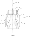
Fig. 4 shows a cross-section of a razor connector according to the present disclosure. -
Fig. 5 shows a bottom view of a razor connector according to the present disclosure. -
Fig. 6 shows an isometric bottom view of a razor connector according to the present disclosure. -
Fig. 7 shows an isometric top view of a razor connector according to the present disclosure and a not connectedrazor cartridge 100. -
Fig. 8 shows an isometric top view of a razor connector according to the present disclosure and aconnected razor cartridge 100. - Hereinafter, a detailed description will be given of the present disclosure. The terms or words used in the description and the aspects of the present disclosure are not to be construed limitedly as only having common-language or dictionary meanings and should, unless specifically defined otherwise in the following description, be interpreted as having their ordinary technical meaning as established in the relevant technical field. The detailed description will refer to specific embodiments to better illustrate the present disclosure, however, it should be understood that the presented disclosure is not limited to these specific embodiments.
- Razor connectors typically comprise multiple components, in particular multiple movable components. The number of components increases the required assembly time during production, as well as the risk of breaking of the razor connector.
- Accordingly, in a first aspect, the present disclosure relates to a
razor connector 10 configured to connect arazor cartridge 100 to arazor handle 12. The razor connector comprises a tongue, configured to allow pivotable movement of therazor cartridge 100 relative to the razor handle 12 and at least one interlocking feature configured to interlock with at least one interlocking part of therazor cartridge 100. Further, the razor connector comprises at least oneflap 16 configured to disconnect therazor cartridge 100 from therazor connector 10 upon actuation. -
Figure 1 illustrates an isometric view of anexemplary razor connector 10 according to the present disclosure with arazor handle 12. Therazor connector 10 may be an individual part and connected to the razor handle 12 by a detachable or non-detachable connection, for example a push-in connection. Manufacturing therazor connector 10 as an individual part may be advantageous if the razor handle 12 can be rapidly and efficiently manufactured, e.g. by injection molding, whereas therazor connector 10 can only be manufactured with more cost and time intensive processes, e.g. additive manufacturing. In that case, an individually manufactured razor handle 12 andrazor connector 10 may reduce the manufacturing time and cost of the complete razor. Further, a releasably attached individually formedrazor connector 10 could be exchanged if it is worn out, while retaining the razor handle 12. Alternatively, therazor connector 10 and the razor handle 12 may be integrally formed, which may reduce the assembly time even further. -
Figure 2 is a close-up top side view of theexemplary razor connector 10 ofFigure 1 .Figure 2 shows a proximal-distalrazor connector axis 24 running centrically through therazor connector 10. In embodiments, thetongue 14 may extend from a distal end of therazor connector 10. Further, therazor connector 10 may be connected to the razor handle 12 at a proximal end (not illustrated, seeFigure 1 ). The distal end and proximal end may define the proximal-distalrazor connector axis 24.Figure 2 further shows twoflaps 16 of theexemplary razor connector 10 being attached to therazor connector 10 towards their distal end. In embodiments, the razor connector may comprise oneflap 16. - In embodiments, the
flap 16 may comprise a proximal 40 and adistal section 42, wherein upon actuation thedistal section 42 is configured to move towards the distal end of therazor connector 10. At theproximal section 40 of the flaps there is a gap between the flaps and therazor connector 10 allowing theproximal section 40 of theflaps 16 to be pushed towards the proximal-distalrazor connector axis 24. The flap's 16distal section 42 may move towards the proximal-distalrazor connector axis 24 when theflap 16, in particular the flap'sproximal section 40, is pushed towards the proximal-distalrazor connector axis 24. Pushing theflap 16, in particular the flap'sproximal section 40, towards the proximal-distalrazor connector axis 24 may be considered an actuation. - The at least one
flap 16 may be shell-shaped, e.g. comprise a wall section forming a cavity, in particular an open cavity. Theflap 16 may be rigid, more specifically the at least one flap may have a Shore D hardness between about 50 to about 120, more specifically between about 55 to about 100 and in particular between about 60 to about 90, measured according to ISO 868:2003. Further, the at least oneflap 16 may have an elongation at break between about 0.5 % to about 60 %, more specifically between about 1.0 % to about 25 % and in particular between about 1.8 % to about 15 %, measured according to ISO 527-1:2019. - In embodiments, the at least one interlocking feature may be a
recess 18, in particular arecess 18 configured to interlock with at least one protrusion of therazor cartridge 100. - In embodiments, the at least one interlocking feature may be an interlocking protrusion, in particular an interlocking protrusion configured to interlock with at least one recess of the
razor cartridge 100. - The interlocking protrusion and the recess may interlock through a snap-fit when the
razor connector 10 is connected to arazor cartridge 100 on its distal end. Therazor connector 10 or parts thereof and/or the razor connector or parts thereof may be flexible, improving the snap fit and allowing release of the snap-fit. When the at least oneflap 16 is actuated, the distal section(s) may move in distal direction and push the razor cartridge towards the distal end. - In embodiments, the at least one
flap 16 may be configured to release the at least one interlocking part of therazor cartridge 100 from the at least one interlocking feature when actuated. In embodiments, the at least oneflap 16 may be configured to disconnect therazor cartridge 100 from therazor connector 10 upon actuation of the at least oneflap 16 by pushing the interlocking part of therazor cartridge 100 out of the interlocking feature, in particular wherein the at least oneflap 16 is configured to disconnect therazor cartridge 100 from therazor connector 10 upon actuation of the at least oneflap 16 by pushing the razor cartridge's 100 protrusion of out of the razor connector's 10recess 18. Pushing the interlocking part of therazor cartridge 100 out of the interlocking feature of therazor connector 10 shall not be construed as requiring theprotrusion 20 to directly contact the interlocking feature or part. The protrusion may merely push against another part of therazor cartridge 100, whereby therazor cartridge 100 moves in distal direction, which in turn may lead to the push out. - As shown in
Figure 2 , in embodiments, the at least oneflap 16 may comprise at least oneprotrusion 20. In particular, the at least oneflap 16 may be integrally formed with at least oneprotrusion 20. The at least oneprotrusion 20 may improve the disconnection mechanism of therazor connector 10. In particular, the at least oneprotrusion 20 may extend towards therazor cartridge 100 when therazor cartridge 100 is connected to therazor connector 10. In embodiments, the at least oneprotrusion 20 may be arranged at thedistal section 42 of the at least oneflap 16. The at least oneprotrusion 20 at thedistal section 42 of theflap 16 may increase the length of movement performed by the flap's 16 distal section, which may in turn push theconnected razor cartridge 100 further away from therazor connector 10. In embodiments, the at least oneprotrusion 20 may be configured to disconnect therazor cartridge 100 from therazor connector 10 upon actuation of the at least oneflap 16 by pushing the interlocking part of therazor cartridge 100 out of the interlocking feature, in particular wherein the at least oneprotrusion 20 is configured to disconnect therazor cartridge 100 from therazor connector 10 upon actuation of the at least oneflap 16 by pushing the razor cartridge's 100 protrusion of out of the razor connector's 10recess 18. - In embodiments, the at least one
flap 16 may be moved away from the proximal-distalrazor connector axis 24 when preloaded. The at least oneflap 16 moving away from the proximal-distalrazor connector axis 24 may increase the distance the flap's 16proximal section 40 needs to move for the actuation, which may reduce the risk of accidental actuation. - In embodiments, moving the at least one
flap 16 towards the proximal-distalrazor connector axis 24 may disconnect therazor cartridge 100 from therazor connector 10. In particular, pushing the at least one flap's 16proximal section 40 towards the proximal-distalrazor connector axis 24 may disconnect therazor cartridge 100 from therazor connector 10. Adisconnected razor cartridge 100 is shown inFigure 7 and aconnected razor cartridge 100 is shown inFigure 8 . - As depicted in
Figure 3 , in embodiments, the at least oneflap 16 may comprise at least oneactuation surface 26 configured to be actuated by a user to release therazor cartridge 100. Theactuation surface 26 may facilitate the actuation by the user. Theactuation surface 26 may be ergonomically shaped and/or comprise a region of higher friction and/or tack e.g. by including a rubber, to improve the handling by the user. - Further, as depicted in
Figure 3 , in embodiments, the at least oneactuation surface 26 may be disposed substantially parallel or parallel to the proximal-distalrazor connector axis 24. Arranging the at least oneactuation surface 26 substantially parallel or parallel to the proximal-distalrazor connector axis 24 may reduce the risk of accidental actuation. For example, if the at least oneactuation surface 26 were arranged orthogonally to the proximal-distalrazor connector axis 24, theactuation surface 26 may be actuated accidentally when pressed against the user's skin during the shaving action. -
Figure 3 further depicts, that in embodiments, the at least oneactuation surface 26 faces away from the proximal-distalrazor connector axis 24. The at least oneactuation surface 26 faces away from the proximal-distalrazor connector axis 24 may be easier to actuate by the user, as no other part may block the access. - In embodiments, the
razor connector 10 may comprise twoflaps 16 opposing one another. This is shown in for exampleFigure 1 . Arranging twoflaps 16 opposing one another, may facilitate actuation of theflaps 16, as the force and reaction force of actuation may both be transferred into theflaps 16. Two opposingflaps 16 may be easily actuatable by a user's hand, in particular with his thumb and index finger. - As shown in
Figure 3 , in embodiments, therazor connector 10 comprises twoactuation surfaces 26 facing away from the proximal-distalrazor connector axis 24 on opposing sides of the proximal-distalrazor connector axis 24. Arranging twoactuation surfaces 24 opposing one another, may facilitate actuation of theflaps 16, as the force and reaction force of actuation may both be transferred into theflaps 16. Two opposing actuation surfaces 24 may be easily actuatable by a user with his hands, in particular his thumb and index finger. - The tongue may connect and/or slide into a corresponding feature of the
razor cartridge 100, as shown inFigure 7 and 8 . The tongue may restrict movement of therazor cartridge 100 relative to therazor connector 10 in certain axis. The tongue may restrict movement of therazor cartridge 100 relative to therazor connector 10 orthogonally to the proximal-distalrazor connector axis 24 and/or pivotable movement around the proximal-distalrazor connector axis 24. This may improve the connection between therazor connector 10 and therazor cartridge 100, in particular it may prevent accidental release of therazor cartridge 100. The tongue may however allow pivotable movement around an axis disposed orthogonally to the proximal-distalrazor connector axis 24. This may in use allow therazor cartridge 100 to align to the surface of a user's skin. The tongue may allow therazor cartridge 100 to align to the user's skin by a pivotable movement but may also apply a restoring force on therazor cartridge 100 to return to its original orientation relative to the razor handle. - In embodiments, the tongue may be connected to a spring, more specifically a spring configured to allow the tongue to move along the proximal-distal
razor connector axis 24 and in particular a spring that compresses and stretches along the proximal-distalrazor connector axis 24. - In embodiments, the tongue may be a
flexible tongue 14. The term "flexible tongue" within this disclosure may refer to an elongated structure, in particular a structure elongated at least partly along the proximal-distalrazor connector axis 24, wherein the elongated structure comprises or consists of an elastic material. The term "flexible tongue" may refer to an elongated structure allowing pivotable movement of a connected part, in particular a razor cartridge" due to elastic deformation. Additionally or alternatively, the term "flexible tongue" may refer to a flexible elongated structure not comprising movable parts, such as springs or slidable parts. - The
flexible tongue 14 may further reduce the assembly time of the razor connector. Further, theflexible tongue 14 may be integrally formed with other parts of therazor connector 10. The term "elastic material" within this disclosure may refer to a material which undergoes deformation when exposed to a force and returns, at least partly, to its original size and shape after the force is removed. Additionally or alternatively, the term "elastic material" within this disclosure may refer to a material which has an elongation at yield of at least 1 %, more specifically at least 1.5 % and in particular at least 2 %, measured according to ISO 527-1:2019. - In embodiments, different parts of the
razor connector 10 may be integrally formed with other parts of therazor connector 10. This may decrease the assembly time of therazor connector 10. - In embodiments, the
flap 16 may be integrally formed with the interlocking feature. - In embodiments, the
flap 16 may be integrally formed with the tongue. - In embodiments, the
flap 16, the interlocking feature and the tongue may be integrally formed. In embodiments, theflap 16, the interlocking feature, in particular a recess, and theflexible tongue 14 may be integrally formed. - In embodiments, the
razor connector 10 may be a one-piece part. Manufacturing therazor connector 10 may decrease the assembly time of therazor connector 10 drastically. In particular, manufacturing therazor connector 10 as a one-piece part may lead to no assembly time for therazor connector 10 at all.Figures 1 to 8 show therazor connector 10 as a one-piece part. - To manufacture the
razor connector 10 as a one-piece part different manufacturing technologies may be used. Therazor connector 10 may be, in some instances, manufacturable by additive manufacturing technologies. Therazor connector 10 may have a complex geometry, which may be efficiently manufacturable by additive manufacturing. In particular, therazor connector 10 may comprise multiple undercuts, which may make for example injection molding inefficient, especially if therazor connector 10 is intended to be manufactured as a one-piece part. - In embodiments, the
razor connector 10 may be formed as a layered structure. The layered structure may comprise a plurality of layers, in particular a plurality of layers substantially parallel to each other. Additive manufacturing technologies, such as fused filament fabrication or material jetting may lead to a plurality of layers, in particular a plurality of layers substantially parallel to each other. - In embodiments, the at least one
protrusion 20 may be configured to preload therazor cartridge 100 when therazor cartridge 100 is connected to therazor connector 10. Preloading therazor cartridge 100 may bias therazor cartridge 100 towards an angle relative to the razor handle 12, which may improve the handling of the razor for the user. - In embodiments, the at least one
flap 16 may be preloaded when therazor cartridge 100 is connected to therazor cartridge 100. Preloading the at least oneflap 16 when connecting therazor cartridge 100 may reduce the required force for actuating the at least oneflap 16 to disconnect the razor cartridge, as at least part of the force is already provided due to the preloading. - As depicted in
Figure 6 andFigure 7 , in embodiments, therazor connector 10 may comprise a receivinghead 22 configured to receive aconnector sleeve 102 of therazor cartridge 100. The receivinghead 22 may align the tongue during its insertion into therazor cartridge 100. Further, the receivinghead 22 may aid in preventing movement of therazor cartridge 100 orthogonally to the proximal-distal axis razor connector proximal-distalrazor connector axis 24. Therazor connector 10 may also connect to therazor connector 100 in other ways, in particular through other types of plug and socket connection types. - In embodiments, the
razor connector 10 may be integrally formed with the razor handle 12. Integrally forming therazor connector 10 with razor handle 12 reduces the assembly time further. - As depicted for example in
Figure 5 , in embodiments, the at least oneflap 16 may be arranged in proximal direction of the receiving head's 22 distal end. Arranging the at least oneflap 16 proximally of the receiving head's 22 distal end may prevent unintentional interaction of theflap 16 with therazor cartridge 100. - In embodiments, the at least one
actuation surface 26 may comprise an indicator, more specifically a haptic indicator and in particular a protrusion, a dot, a cavity, a groove and/or a rubber element. The haptic indicator may facilitate the identification of theactuation surface 26 by the user, in particular without looking at therazor connector 10 and only through haptic perception. - In embodiments, the
razor connector 10 may have a top side 32 (shown inFigure 2 ) and a bottom side 36 (shown inFigure 5 ). Thetop side 32 may be the side facing against a shaving direction and thebottom side 36 the side facing towards the shaving direction. Alternatively or additionally, the top 32 and bottom 36 side may be defined relative to other components. The top 32 andbottom side 36 may be surfaces disposed parallel to the movement of the at least oneflap 16 when the flap is actuated. Alternatively or additionally, the bottom side may be the razor connector's 10 side comprising the tongue, in particular theflexible tongue 14. Alternatively or additionally, the bottom side may be the razor connector's 10 side comprising the interlocking feature. Additionally, thetop side 32 may be the side opposite of thebottom side 36. - As depicted in
Figures 3 ,4 and6 , in embodiments, the tongue may comprise a first section extending parallel to the proximal-distalrazor connector axis 24 along thebottom side 36 of therazor connector 10 and a second section diverging towards thetop side 32 of therazor connector 10. This configuration may, in instances, be selected to allow therazor cartridge 100 to pivot relative to an axis disposed orthogonally to the proximal-distalrazor connector axis 24, while preventing movement orthogonally to the proximal-distalrazor connector axis 24. - In embodiments, the receiving
head 22 may comprise a top side 34 (shown inFigure 2 ) and a bottom side 38 (shown inFigure 5 ). The top 34 andbottom side 38 of the receivinghead 22 may be defined accordingly to the top 32 andbottom side 36 of therazor connector 10. As shown infigure 5 and 6 theflexible tongue 14 may be connected to the receivinghead 22, more specifically to the receiving head's 22 proximal end and in particular the receiving head's 22 bottom side's 38 proximal end. This configuration may increase the length of the tongue, which may allow for a greater deflection at the same force compared to a shorter tongue, which may improve the alignment of therazor cartridge 100 to the user's skin during the shaving action. - In embodiments, the tongue may have a polygonal cross-section, more specifically a square, rectangular or octagonal shape and in particular a rectangular shape.
- In embodiments, a corner of the polygonal cross-section may be round. The rounded edges may facilitate sliding the tongue into the razor cartridge's 100 corresponding feature.
- In embodiments, the at least one
protrusion 20 may be placed at thetop side 32 of therazor connector 10, in particular on the at least one flap's 16distal section 42 at thetop side 32. In embodiments, the at least oneprotrusion 20 may be placed at thebottom side 36 of therazor connector 10, in particular on the at least one flap's 16distal section 42 at thebottom side 36. As shown inFigure 5 and Figure 6 , the at least oneflap 16 may comprise at least oneprotrusion 20 on the at least one flap's 16distal section 42 at both thetop side 32 andbottom side 36. This configuration may improve the release of therazor cartridge 100. Aprotrusion 20 placed only at thetop side 32 orbottom side 36 may only tilt therazor cartridge 100 when the at least oneflap 16 is actuated. A protrusion at both the top side during the actuation of the at least oneflap 16 push therazor cartridge 100 straight towards the razor connector's 10 distal end, which may release therazor cartridge 100. However, it may also be sufficient to place the at least oneprotrusion 20 at only either thetop side 32 or thebottom side 36. In particular, if the at least oneprotrusion 20 is placed on the side comprising the interlocking feature, in particular therecess 18, the at least oneprotrusion 20 may push therazor cartridge 100 so far towards the distal end on that side, that therazor cartridge 100 is released from therazor connector 10, although theoverall razor cartridge 100 only tilts relative to therazor connector 10. - In embodiments, the interlocking feature may be positioned proximally of the receiving head's 22 distal end, more specifically on the bottom side of the
razor connector 10 on the receivinghead 22 proximally of the receiving head's 22 distal end and in particular on the bottom side of therazor connector 10 on the receivinghead 22 proximally of the receiving head's 22 distal end adjacent to the tongue. Placing the interlocking feature, in particular arecess 18 on thebottom side 38 of therazor connector 10 may be used e.g. if thebottom side 38 of therazor connector 10 is facing against the shaving direction, in some instances, as during the shaving action the interlocking feature may be pressed together, due to the forces transferred to therazor cartridge 100 during the shaving action. - As mentioned above, in embodiments, the
razor connector 10 may comprise a plurality of layers, in particular a plurality of layers substantially parallel to each other. In embodiments, a layer of the plurality of layers may have a thickness between about 5 µm to about 100 µm, more specifically between about 10 µm to about 50 µm and in particular between about 15 µm to about 30 µm. - In embodiments, a layer of the plurality of layers may have a thickness between about 0.05 mm to about 0.6 mm, more specifically between about 0.1 µm to about 0.4 mm and in particular between about 0.15 mm to about 0.3 mm.
- The thickness of the plurality of layers may depend upon the process used for manufacturing. Further, a smaller layer thickness may lead to an increased manufacturing time of the
razor connector 10, but may also increase the mechanical stability and dimensional accuracy of therazor connector 10. - In embodiments, the
razor connector 10 may comprise a first polymer, more specifically a photopolymer and in particular an ABS-like polymer and/or polypropylene-like polymer. A photopolymer and in particular an ABS-like polymer and/or polypropylene-like polymer may be processable by an additive manufacturing process such as stereolithography. The first polymer may have a Shore D hardness between about 50 to about 120, more specifically between about 55 to about 100 and in particular between about 60 to about 90, measured according to ISO 868:2003. The first polymer may be for example Durus or Rigur, by the company Stratasys, Ltd. - In embodiments, the
razor connector 10 may comprise a second polymer. The second polymer may have a shore A hardness between about 10 to about 95, more specifically between about 25 to about 80 and in particular between about 35 to about 60, measured according to ASTM D2240 - 15. The second polymer may be for example Tango or Agilus 30, by the company Stratasys, Ltd. - In embodiments, the
razor connector 10 may comprise a third polymer, more specifically a thermoplastic polymer and in particular ABS and/or polypropylene. - In embodiments, the
razor connector 10 may comprise a fourth polymer, more specifically a thermoplastic elastomer and in particular a TPA, a TPC, a TPO, a TPS, a TPV, a TPZ and/or a TPU. - Thermoplastic elastomers, as well as ABS and/or polypropylene may be processable by technologies wherein a solid material is liquified and subsequently resolidified for manufacturing, for example extrusion. Thermoplastic elastomers, as well as ABS and/or polypropylene may in particular be processable by additive manufacturing technologies such as fused filament fabrication and/or selective laser melting.
- Additive manufacturing technologies may also be employed as multi-material processes, wherein a one-piece part comprising at least two different materials can be manufactured. For example, stereolithography and fused filament fabrication may be used to create multi-material parts. In fused filament fabrication the manufacturing device, e.g. the 3D-printer, may comprise multiple nozzles, wherein each nozzle is configured to extrude a different polymer. In stereolithography the part to be produced may change between vats comprising different precursors. Hence, additive manufacturing may be employed to optimize properties of certain parts and/or regions of the
razor connector 10 by varying the choice of material locally. - The second and/or fourth polymer may have a lower modulus of elasticity compared to the first and/or third polymer. A material with a lower modulus of elasticity exhibits a higher degree of deformation when exposed to the same force compared to a material with a higher modulus of elasticity. The second and/or fourth polymer may have a lower hardness, in particular shore A and/or shore D hardness, compared to the first and/or third polymer, which may allow for a higher degree of deformation of the second and/or fourth compared to the first and/or third polymer when exposed to the same force.
- In embodiments, the at least one
flap 16 may be connected to therazor connector 10 at at least oneconnection shoulder 28, as shown inFigure 4 . In embodiments, the at least oneflap 16 may be connected to the receivinghead 22 at at least oneconnection shoulder 28. In embodiments, the at least oneflap 16 may perform a hinge-type movement relative to therazor connector 10 in particular a hinge-type movement wherein theconnection shoulder 28 acts as an axis of rotation. In embodiments, the at least oneflap 16 may perform a hinge-type movement relative to the receivinghead 22 in particular a hinge-type movement wherein theconnection shoulder 28 acts as an axis of rotation. The term "hinge-type movement" within this disclosure is well-known in the art and attributed its common meaning in this technical field. In some embodiments, the term "hinge-type movement" may refer to the at least oneflap 16 performing a rotational movement relative to the razor connector and/or receivinghead 22 around theconnection shoulder 28. The at least one flap may be connected to the receivinghead 22 at twoconnection shoulders 28, wherein one connection shoulder is positioned on thetop side 32 and/ortop side 34 of the receivinghead 22 and wherein one connection shoulder is positioned at thebottom side 36 and/orbottom side 38 of the receivinghead 22. In embodiments, theconnection shoulder 28 may comprise the second and/or fourth polymer. In embodiments, theconnection shoulder 28 may comprise the second and/or fourth polymer and the at least oneflap 16 and/or the receivinghead 22 comprise the first and/or third polymer. Manufacturing theconnection shoulder 28 with a material exhibiting lower modulus of elasticity may reduce the required force to actuate the at least oneflap 16. - In embodiments, the
flexible tongue 14 may comprise the first and/or third polymer. In embodiments, theflexible tongue 14 may comprise the second and/or fourth polymer. Theflexible tongue 14 comprising the second and/or fourth polymer, more specifically a second and/or fourth polymer exhibiting a lower modulus of elasticity compared to the first and/or third, may in use allow therazor cartridge 100 to align to the skin of the user under less force. However, aflexible tongue 14 comprising the first and/or third polymer with a higher modulus of elasticity may provide a higher stability to therazor cartridge 100. In embodiments, theflexible tongue 14 may comprise the first and/or third polymer and the second and/or fourth polymer. This may allow adjusting the flexible tongue's 14 modulus of elasticity to an optimized value. - In embodiments, the at least one
flap 16 may comprise the first and/or third polymer. - In embodiments, the
protrusion 20 may comprise the first and/or third polymer. The at least oneflap 16 and/orprotrusion 20 comprising the first and/or third polymer, more specifically a first and/or third polymer exhibiting a higher modulus of elasticity may lead to a higher rigidity of the parts which may improve the actuation mechanism, in particular the release of therazor cartridge 100 upon actuation. A higher rigidity of the at least oneflap 16 may lead to a higher proportion of the force applied during actuation to be transferred to theprotrusion 20, in particular as less force is absorbed by elastic deformation of theflap 16. Similarly, a higher rigidity of theprotrusion 20 may lead to a higher force transfer to therazor cartridge 100, as less force is absorbed by elastic deformation of theprotrusion 20. - In embodiments, the actuation surface may comprise the second and/or fourth polymer. The second and/or fourth polymer may have a higher tack and/or coefficient of friction compared to the second and/or fourth polymer and may therefore provide better grip to the user.
- In a second aspect, the present disclosure relates to a razor system comprising a
razor connector 10 according to any preceding embodiment and arazor cartridge 100, wherein therazor cartridge 100 is releasably attached to therazor connector 10. - In embodiments, the razor system may further comprise a
razor handle 12 connected to therazor connector 10. - In a third aspect, the present disclosure relates to a process for manufacturing a
razor connector 10 according to any preceding embodiment comprising additive manufacturing, material jetting, fused filament fabrication, stereolithography and/or selective laser sintering. -
- 1. A razor connector (10) configured to connect a razor cartridge (100) to a razor handle (12) comprising:
- a tongue, configured to allow pivotable movement of the razor cartridge (100) relative to the razor handle (12);
- at least one interlocking feature configured to interlock with at least one interlocking part of the razor cartridge (100);
- at least one flap (16) configured to disconnect the razor cartridge (100) from the razor connector (10) upon actuation.
- 2. The razor connector (10) according to aspect 1, wherein the tongue is a flexible tongue (14).
- 3. The razor connector (10) according to any preceding aspect, wherein the at least one interlocking feature is a recess (18), in particular a recess (18) configured to interlock with at least one interlocking protrusion of the razor cartridge (100).
- 4. The razor connector (10) according to aspect 1 or 2, wherein the at least one interlocking feature is an interlocking protrusion, in particular an interlocking protrusion configured to interlock with at least one recess of the razor cartridge (100)
- 5. The razor connector (10) according to any preceding aspect, wherein the flap (16) is integrally formed with the interlocking feature.
- 6. The razor connector (10) according to any preceding aspect, wherein the flap (16) is integrally formed with the tongue.
- 7. The razor connector (10) according to any preceding aspect, wherein the flap (16), the interlocking feature and the tongue are integrally formed.
- 8. The razor connector (10) according to any preceding aspect, wherein the razor connector (10) is a one-piece part.
- 9. The razor connector (10) according to any preceding aspect, wherein the razor connector (10) comprises a plurality of layers, in particular a plurality of layers substantially parallel to each other.
- 10. The razor connector (10) according to any preceding aspect, wherein the at least one flap (16) is configured to release the at least one interlocking part of the razor cartridge (100) from the at least one interlocking feature when actuated.
- 11. The razor connector (10) according to any preceding aspect, wherein the at least one flap (16) comprises a protrusion (20), in particular a protrusion (20) extending towards the razor cartridge (100) when the razor cartridge (100) is connected to the razor connector (10).
- 12. The razor connector (10) according to aspect 11, wherein the protrusion (20) is configured to disconnect the razor cartridge (100) from the razor connector (10) upon actuation of the at least one flap (16) by pushing the interlocking part of the razor cartridge (100) out of the interlocking feature, in particular wherein the protrusion (20) is configured to disconnect the razor cartridge (100) from the razor connector (10) upon actuation of the at least one flap (16) by pushing the razor cartridge's (100) protrusion of out of the razor connector's (10) recess (18).
- 13. The razor connector (10) according to
aspect 11 or 12, wherein the protrusion (20) is configured to preload the razor cartridge (100) when the razor cartridge (100) is connected to the razor connector (10). - 14. The razor connector (10) according to any preceding aspect, wherein the at least one flap (16) is preloaded when the razor cartridge (100) is connected to the razor cartridge (100).
- 15. The razor connector (10) according to any preceding aspect, wherein the razor connector (10) comprises two flaps (16) opposing one another.
- 16. The razor connector (10) according to any preceding aspect, wherein the razor connector (10) comprises a receiving head (22) configured to receive a connector sleeve (102) of the razor cartridge (100).
- 17. The razor connector (10) according to any preceding aspect, wherein the razor connector (10) is integrally formed with the razor handle (12).
- 18. The razor connector (10) according to any preceding aspect, wherein the tongue extends from a distal end of the razor connector (10) and wherein the razor connector (10) is connected to the razor handle (12) at a proximal end and wherein the distal end and proximal end define a proximal-distal razor connector axis (24).
- 19. The razor connector (10) according to any one of
aspects 16 to 18, wherein the at least one flap (16) is arranged in proximal direction of the receiving head's (22) distal end. - 20. The razor connector (10) according to any one of aspects 11 to 19, wherein the protrusion (20) is arranged at the distal end of the at least one flap (16).
- 21. The razor connector (10) according to any preceding aspect, wherein the at least one flap (16) comprises at least one actuation surface (26) configured to be actuated by a user to release the razor cartridge (100).
- 22. The razor connector (10) according to aspect 21, wherein the at least one actuation surface (26) is disposed substantially parallel to the proximal-distal razor connector (10) axis.
- 23. The razor connector (10) according to any one of aspects 21 to 22, wherein the at least one actuation surface (26) faces away from the proximal-distal razor connector (10) axis.
- 24. The razor connector (10) according to any one of aspects 21 to 23, wherein the at least one actuation surface (26) comprises an indicator, more specifically a haptic indicator and in particular a protrusion (20), a dot, a cavity, a groove and/or a rubber element.
- 25. The razor connector (10) according to
aspect 18 or 19 to 24 when dependent onaspect 18, wherein the at least one flap (16) is moved away from the proximal-distal razor connector axis (24) when preloaded. - 26. The razor connector (10) according to aspect 25, wherein moving the at least one flap (16) towards the proximal-distal razor connector axis (24) disconnects the razor cartridge (100) from the razor connector (10).
- 27. The razor connector (10) according to any preceding aspect, wherein the razor connector (10) has a top side (32) and bottom side (36).
- 28. The razor connector (10) according to aspect 27, wherein the tongue comprises a first section extending parallel to the proximal-distal razor connector axis (24) along the bottom side (36) of the razor connector (10) and a second section diverging towards the top side (32) of the razor connector (10).
- 29. The razor connector (10) according to any preceding aspect, wherein the tongue has a polygonal cross-section, more specifically a square, rectangular or octagonal shape and in particular a rectangular shape.
- 30. The razor connector (10) according to aspect 29, wherein a corner of the polygonal cross-section is round.
- 31. The razor connector (10) according to any one of aspects 27 to 30, wherein the flap (16) comprises the at least one protrusion (20) on the at least one flap's (16) distal section (42) at both the top side (32) and bottom side (36).
- 32. The razor connector (10) according to any one of
aspects 16 to 31, wherein the interlocking feature is positioned proximally of the receiving head's (22) distal end, more specifically on the bottom side (36) of the razor connector (10) on the receiving head (22) proximally of the receiving head's (22) distal end and in particular on the bottom side (36) of the razor connector (10) on the receiving head (22) proximally of the receiving head's (22) distal end adjacent to the tongue. - 33. The razor connector (10) according to any one of aspects 9 to 32, wherein a layer of the plurality of layers has a thickness between about 5 µm to about 100 µm, more specifically between about 10 µm to about 50 µm and in particular between about 15 µm to about 30 µm.
- 34. The razor connector (10) according to any one of aspects 9 to 32, wherein a layer of the plurality of layers has a thickness between about 0.05 mm to about 0.6 mm, more specifically between about 0.1 µm to about 0.4 mm and in particular between about 0.15 mm to about 0.3 mm.
- 35. The razor connector (10) according to any preceding aspect, wherein the razor connector (10) comprises a first polymer, more specifically a photopolymer and in particular an ABS-like polymer and/or polypropylene-like polymer.
- 36. The razor connector (10) according to aspect 35, wherein the first polymer has a Shore D hardness between about 50 to about 120, more specifically between about 55 to about 100 and in particular between about 60 to about 90, measured according to ISO 868:2003.
- 37. The razor connector (10) according to any preceding aspect, wherein the razor connector (10) comprises a second polymer.
- 38. The razor connector (10) according to aspect 37, wherein the second polymer has a shore A hardness between about 10 to about 95, more specifically between about 25 to about 80 and in particular between about 35 to about 60, measured according to ASTM D2240 - 15.
- 39. The razor connector (10) according to any preceding aspect, wherein the razor connector (10) comprises a third polymer, more specifically a thermoplastic polymer and in particular ABS and/or polypropylene.
- 40. The razor connector (10) according to any preceding aspect, wherein the razor connector (10) comprises a fourth polymer, more specifically a thermoplastic elastomer and in particular a TPA, a TPC, a TPO, a TPS, a TPV, a TPZ and/or a TPU.
- 41. The razor connector (10) according to one of aspects 37 to 40, wherein the at least one flap (16) is connected to the receiving head (22) at a connection shoulder (28), wherein the connection shoulder (28) comprises the second and/or fourth polymer.
- 42. The razor connector (10) according to any one of aspects 37 to 41, wherein the flexible tongue (14) comprises the second and/or fourth polymer.
- 43. The razor connector (10) according to any one of aspects 35 to 42, wherein the flap (16) comprises the first and/or third polymer.
- 44. The razor connector (10) according to any one of aspects 35 to 43, wherein the protrusion (20) comprises the first and/or third polymer.
- 45. The razor connector (10) according to any one of aspects preceding aspect, wherein the tongue is connected to a spring, more specifically a spring configured to allow the tongue to move along the proximal-distal razor connector (10) axis and in particular a spring that compresses and stretches along the proximal-distal razor connector (10) axis.
- 46. A razor system comprising a razor connector (10) according to any preceding aspect and a razor cartridge (100), wherein the razor cartridge (100) is releasably attached to the razor connector (10).
- 47. The razor system according to aspect 46, wherein the razor system further comprises a razor handle (12) connected to the razor connector (10).
- 48. A process for manufacturing a razor connector (10) according to any of aspects 1-45 comprising:
additive manufacturing, material jetting, fused filament fabrication, stereolithography and/or selective laser sintering.
Claims (15)
- A razor connector (10) configured to connect a razor cartridge (100) to a razor handle (12) comprising:a tongue, configured to allow pivotable movement of the razor cartridge (100) relative to the razor handle (12);at least one interlocking feature configured to interlock with at least one interlocking part of the razor cartridge (100);at least one flap (16) configured to disconnect the razor cartridge (100) from the razor connector (10) upon actuation.
- The razor connector (10) according to claim 1, wherein the tongue is a flexible tongue (14).
- The razor connector (10) according to any preceding claim, wherein the at least one interlocking feature is a recess (18), in particular a recess (18) configured to interlock with at least one interlocking protrusion of the razor cartridge (100).
- The razor connector (10) according to any preceding claim, wherein the flap (16) is integrally formed with the interlocking feature.
- The razor connector (10) according to any preceding claim, wherein the razor connector (10) is a one-piece part.
- The razor connector (10) according to any preceding claim, wherein the razor connector (10) comprises a plurality of layers, in particular a plurality of layers substantially parallel to each other.
- The razor connector (10) according to any preceding claim, wherein the at least one flap (16) is configured to release the at least one interlocking part of the razor cartridge (100) from the at least one interlocking feature when actuated.
- The razor connector (10) according to any preceding claim, wherein the at least one flap (16) comprises a protrusion (20), in particular a protrusion (20) extending towards the razor cartridge (100) when the razor cartridge (100) is connected to the razor connector (10).
- The razor connector (10) according to claim 8, wherein the protrusion (20) is configured to disconnect the razor cartridge (100) from the razor connector (10) upon actuation of the at least one flap (16) by pushing the interlocking part of the razor cartridge (100) out of the interlocking feature, in particular wherein the protrusion (20) is configured to disconnect the razor cartridge (100) from the razor connector (10) upon actuation of the at least one flap (16) by pushing the razor cartridge's (100) protrusion of out of the razor connector's (10) recess (18).
- The razor connector (10) according to claim 8 or 9, wherein the protrusion (20) is configured to preload the razor cartridge (100) when the razor cartridge (100) is connected to the razor connector (10).
- The razor connector (10) according to any preceding claim, wherein the razor connector (10) comprises two flaps (16) opposing one another.
- The razor connector (10) according to any preceding claim, wherein the at least one flap (16) is arranged in proximal direction of a receiving head's (22) distal end.
- The razor connector (10) according to any preceding claim, wherein the razor connector has a top side (32) and bottom side (36) and wherein the tongue extends from a distal end of the razor connector (10) and wherein the razor connector (10) is connected to the razor handle (12) at a proximal end and wherein the distal end and proximal end define a proximal-distal razor connector axis (24) and wherein the tongue comprises a first section extending parallel to the proximal-distal razor connector axis (24) along the bottom side (36) of the razor connector (10) and a second section diverging towards the top side (32) of the razor connector (10).
- A razor system comprising a razor connector (10) according to any preceding claim and a razor cartridge (100), wherein the razor cartridge (100) is releasably attached to the razor connector (10).
- A process for manufacturing a razor connector (10) according to any one of claims 1 to 13 comprising:
additive manufacturing, material jetting, fused filament fabrication, stereolithography and/or selective laser sintering.
Priority Applications (4)
| Application Number | Priority Date | Filing Date | Title |
|---|---|---|---|
| EP21215575.8A EP4197725B1 (en) | 2021-12-17 | 2021-12-17 | Razor connector |
| US18/715,518 US20260115951A1 (en) | 2021-12-17 | 2022-12-16 | Razor connector |
| PCT/EP2022/086381 WO2023111281A1 (en) | 2021-12-17 | 2022-12-16 | Razor connector |
| KR1020247023170A KR20240119304A (en) | 2021-12-17 | 2022-12-16 | razor connector |
Applications Claiming Priority (1)
| Application Number | Priority Date | Filing Date | Title |
|---|---|---|---|
| EP21215575.8A EP4197725B1 (en) | 2021-12-17 | 2021-12-17 | Razor connector |
Publications (2)
| Publication Number | Publication Date |
|---|---|
| EP4197725A1 true EP4197725A1 (en) | 2023-06-21 |
| EP4197725B1 EP4197725B1 (en) | 2025-07-23 |
Family
ID=78957223
Family Applications (1)
| Application Number | Title | Priority Date | Filing Date |
|---|---|---|---|
| EP21215575.8A Active EP4197725B1 (en) | 2021-12-17 | 2021-12-17 | Razor connector |
Country Status (4)
| Country | Link |
|---|---|
| US (1) | US20260115951A1 (en) |
| EP (1) | EP4197725B1 (en) |
| KR (1) | KR20240119304A (en) |
| WO (1) | WO2023111281A1 (en) |
Citations (4)
| Publication number | Priority date | Publication date | Assignee | Title |
|---|---|---|---|---|
| DE8815015U1 (en) * | 1988-12-02 | 1989-01-19 | Wilkinson Sword GmbH, 5650 Solingen | razor |
| EP0951971A1 (en) * | 1998-04-22 | 1999-10-27 | Warner-Lambert Company | Disposable razor-cartridge holder for single direction pivoting cartridge |
| US20170087732A1 (en) * | 2015-09-29 | 2017-03-30 | The Gillette Company | Adapter For Attaching A Razor Cartridge To A Razor Handle |
| US20200070375A1 (en) * | 2018-09-05 | 2020-03-05 | The Gillette Company Llc | Razor structure |
Family Cites Families (6)
| Publication number | Priority date | Publication date | Assignee | Title |
|---|---|---|---|---|
| US4446619A (en) * | 1982-06-07 | 1984-05-08 | The Gillette Company | Razor handle |
| ZA951404B (en) * | 1994-02-23 | 1996-02-09 | Creanova Ag | Hinge arrangement |
| US8480166B1 (en) * | 2012-04-30 | 2013-07-09 | GM Global Technology Operations LLC | Air ducts for vehicles |
| JP1545561S (en) * | 2014-11-13 | 2016-03-14 | ||
| JP7164597B2 (en) * | 2017-08-28 | 2022-11-01 | エッジウェル パーソナル ケア ブランズ リミテッド ライアビリティ カンパニー | razor cartridge connector |
| US12122059B2 (en) * | 2021-05-25 | 2024-10-22 | The Gillette Company Llc | Integrated spring element |
-
2021
- 2021-12-17 EP EP21215575.8A patent/EP4197725B1/en active Active
-
2022
- 2022-12-16 US US18/715,518 patent/US20260115951A1/en active Pending
- 2022-12-16 KR KR1020247023170A patent/KR20240119304A/en active Pending
- 2022-12-16 WO PCT/EP2022/086381 patent/WO2023111281A1/en not_active Ceased
Patent Citations (4)
| Publication number | Priority date | Publication date | Assignee | Title |
|---|---|---|---|---|
| DE8815015U1 (en) * | 1988-12-02 | 1989-01-19 | Wilkinson Sword GmbH, 5650 Solingen | razor |
| EP0951971A1 (en) * | 1998-04-22 | 1999-10-27 | Warner-Lambert Company | Disposable razor-cartridge holder for single direction pivoting cartridge |
| US20170087732A1 (en) * | 2015-09-29 | 2017-03-30 | The Gillette Company | Adapter For Attaching A Razor Cartridge To A Razor Handle |
| US20200070375A1 (en) * | 2018-09-05 | 2020-03-05 | The Gillette Company Llc | Razor structure |
Also Published As
| Publication number | Publication date |
|---|---|
| EP4197725B1 (en) | 2025-07-23 |
| WO2023111281A1 (en) | 2023-06-22 |
| US20260115951A1 (en) | 2026-04-30 |
| KR20240119304A (en) | 2024-08-06 |
Similar Documents
| Publication | Publication Date | Title |
|---|---|---|
| US20240083053A1 (en) | Razor connector | |
| EP2195146B1 (en) | Razor system comprising a handle | |
| EP3842196B1 (en) | Coupling mechanism | |
| EP3659762B1 (en) | A shaver's handle with a lock and release mechanism for engaging and disengaging a razor cartridge | |
| EP2265422B1 (en) | Razor handle for a retractable shaving cartridge and a razor comprising such a razor handle | |
| EP2026935B1 (en) | Razor handle | |
| EP3565690B1 (en) | Razor cartridge connector | |
| AU3563302A (en) | Razor cartridge loading system | |
| WO2008094488A1 (en) | Razor handle | |
| KR20240145919A (en) | Razor Assembly | |
| WO2017174120A1 (en) | A shaver's handle with a lock and release mechanism for engaging and disengaging a razor cartridge | |
| WO2013066875A1 (en) | Ambidextrous utility knife | |
| US20260115951A1 (en) | Razor connector | |
| EP4335603A1 (en) | Razor connector | |
| EP4335602A1 (en) | Razor connector | |
| EP3912773A1 (en) | Razor head with improved spring fingers | |
| US11648700B2 (en) | Skincare device handle with flexible portion | |
| EP4706920A1 (en) | Razor handle |
Legal Events
| Date | Code | Title | Description |
|---|---|---|---|
| PUAI | Public reference made under article 153(3) epc to a published international application that has entered the european phase |
Free format text: ORIGINAL CODE: 0009012 |
|
| STAA | Information on the status of an ep patent application or granted ep patent |
Free format text: STATUS: THE APPLICATION HAS BEEN PUBLISHED |
|
| AK | Designated contracting states |
Kind code of ref document: A1 Designated state(s): AL AT BE BG CH CY CZ DE DK EE ES FI FR GB GR HR HU IE IS IT LI LT LU LV MC MK MT NL NO PL PT RO RS SE SI SK SM TR |
|
| STAA | Information on the status of an ep patent application or granted ep patent |
Free format text: STATUS: REQUEST FOR EXAMINATION WAS MADE |
|
| 17P | Request for examination filed |
Effective date: 20231213 |
|
| RBV | Designated contracting states (corrected) |
Designated state(s): AL AT BE BG CH CY CZ DE DK EE ES FI FR GB GR HR HU IE IS IT LI LT LU LV MC MK MT NL NO PL PT RO RS SE SI SK SM TR |
|
| GRAP | Despatch of communication of intention to grant a patent |
Free format text: ORIGINAL CODE: EPIDOSNIGR1 |
|
| STAA | Information on the status of an ep patent application or granted ep patent |
Free format text: STATUS: GRANT OF PATENT IS INTENDED |
|
| INTG | Intention to grant announced |
Effective date: 20250310 |
|
| GRAS | Grant fee paid |
Free format text: ORIGINAL CODE: EPIDOSNIGR3 |
|
| GRAA | (expected) grant |
Free format text: ORIGINAL CODE: 0009210 |
|
| STAA | Information on the status of an ep patent application or granted ep patent |
Free format text: STATUS: THE PATENT HAS BEEN GRANTED |
|
| AK | Designated contracting states |
Kind code of ref document: B1 Designated state(s): AL AT BE BG CH CY CZ DE DK EE ES FI FR GB GR HR HU IE IS IT LI LT LU LV MC MK MT NL NO PL PT RO RS SE SI SK SM TR |
|
| REG | Reference to a national code |
Ref country code: GB Ref legal event code: FG4D |
|
| REG | Reference to a national code |
Ref country code: CH Ref legal event code: EP |
|
| REG | Reference to a national code |
Ref country code: IE Ref legal event code: FG4D |
|
| REG | Reference to a national code |
Ref country code: DE Ref legal event code: R096 Ref document number: 602021034530 Country of ref document: DE |
|
| REG | Reference to a national code |
Ref country code: NL Ref legal event code: MP Effective date: 20250723 |
|
| PG25 | Lapsed in a contracting state [announced via postgrant information from national office to epo] |
Ref country code: PT Free format text: LAPSE BECAUSE OF FAILURE TO SUBMIT A TRANSLATION OF THE DESCRIPTION OR TO PAY THE FEE WITHIN THE PRESCRIBED TIME-LIMIT Effective date: 20251124 |
|
| PG25 | Lapsed in a contracting state [announced via postgrant information from national office to epo] |
Ref country code: NL Free format text: LAPSE BECAUSE OF FAILURE TO SUBMIT A TRANSLATION OF THE DESCRIPTION OR TO PAY THE FEE WITHIN THE PRESCRIBED TIME-LIMIT Effective date: 20250723 |
|
| REG | Reference to a national code |
Ref country code: AT Ref legal event code: MK05 Ref document number: 1815981 Country of ref document: AT Kind code of ref document: T Effective date: 20250723 |
|
| PG25 | Lapsed in a contracting state [announced via postgrant information from national office to epo] |
Ref country code: IS Free format text: LAPSE BECAUSE OF FAILURE TO SUBMIT A TRANSLATION OF THE DESCRIPTION OR TO PAY THE FEE WITHIN THE PRESCRIBED TIME-LIMIT Effective date: 20251123 |
|
| PGFP | Annual fee paid to national office [announced via postgrant information from national office to epo] |
Ref country code: GB Payment date: 20251218 Year of fee payment: 5 |
|
| PG25 | Lapsed in a contracting state [announced via postgrant information from national office to epo] |
Ref country code: NO Free format text: LAPSE BECAUSE OF FAILURE TO SUBMIT A TRANSLATION OF THE DESCRIPTION OR TO PAY THE FEE WITHIN THE PRESCRIBED TIME-LIMIT Effective date: 20251023 |
|
| REG | Reference to a national code |
Ref country code: LT Ref legal event code: MG9D |
|
| PG25 | Lapsed in a contracting state [announced via postgrant information from national office to epo] |
Ref country code: AT Free format text: LAPSE BECAUSE OF FAILURE TO SUBMIT A TRANSLATION OF THE DESCRIPTION OR TO PAY THE FEE WITHIN THE PRESCRIBED TIME-LIMIT Effective date: 20250723 |
|
| PG25 | Lapsed in a contracting state [announced via postgrant information from national office to epo] |
Ref country code: FI Free format text: LAPSE BECAUSE OF FAILURE TO SUBMIT A TRANSLATION OF THE DESCRIPTION OR TO PAY THE FEE WITHIN THE PRESCRIBED TIME-LIMIT Effective date: 20250723 |
|
| PG25 | Lapsed in a contracting state [announced via postgrant information from national office to epo] |
Ref country code: HR Free format text: LAPSE BECAUSE OF FAILURE TO SUBMIT A TRANSLATION OF THE DESCRIPTION OR TO PAY THE FEE WITHIN THE PRESCRIBED TIME-LIMIT Effective date: 20250723 |
|
| PGFP | Annual fee paid to national office [announced via postgrant information from national office to epo] |
Ref country code: FR Payment date: 20251217 Year of fee payment: 5 |
|
| PG25 | Lapsed in a contracting state [announced via postgrant information from national office to epo] |
Ref country code: GR Free format text: LAPSE BECAUSE OF FAILURE TO SUBMIT A TRANSLATION OF THE DESCRIPTION OR TO PAY THE FEE WITHIN THE PRESCRIBED TIME-LIMIT Effective date: 20251024 |
|
| PG25 | Lapsed in a contracting state [announced via postgrant information from national office to epo] |
Ref country code: SE Free format text: LAPSE BECAUSE OF FAILURE TO SUBMIT A TRANSLATION OF THE DESCRIPTION OR TO PAY THE FEE WITHIN THE PRESCRIBED TIME-LIMIT Effective date: 20250723 |
|
| PG25 | Lapsed in a contracting state [announced via postgrant information from national office to epo] |
Ref country code: LV Free format text: LAPSE BECAUSE OF FAILURE TO SUBMIT A TRANSLATION OF THE DESCRIPTION OR TO PAY THE FEE WITHIN THE PRESCRIBED TIME-LIMIT Effective date: 20250723 |
|
| PG25 | Lapsed in a contracting state [announced via postgrant information from national office to epo] |
Ref country code: PL Free format text: LAPSE BECAUSE OF FAILURE TO SUBMIT A TRANSLATION OF THE DESCRIPTION OR TO PAY THE FEE WITHIN THE PRESCRIBED TIME-LIMIT Effective date: 20250723 Ref country code: BG Free format text: LAPSE BECAUSE OF FAILURE TO SUBMIT A TRANSLATION OF THE DESCRIPTION OR TO PAY THE FEE WITHIN THE PRESCRIBED TIME-LIMIT Effective date: 20250723 |
|
| PG25 | Lapsed in a contracting state [announced via postgrant information from national office to epo] |
Ref country code: RS Free format text: LAPSE BECAUSE OF FAILURE TO SUBMIT A TRANSLATION OF THE DESCRIPTION OR TO PAY THE FEE WITHIN THE PRESCRIBED TIME-LIMIT Effective date: 20251023 |
|
| PG25 | Lapsed in a contracting state [announced via postgrant information from national office to epo] |
Ref country code: ES Free format text: LAPSE BECAUSE OF FAILURE TO SUBMIT A TRANSLATION OF THE DESCRIPTION OR TO PAY THE FEE WITHIN THE PRESCRIBED TIME-LIMIT Effective date: 20250723 |
|
| PG25 | Lapsed in a contracting state [announced via postgrant information from national office to epo] |
Ref country code: RO Free format text: LAPSE BECAUSE OF FAILURE TO SUBMIT A TRANSLATION OF THE DESCRIPTION OR TO PAY THE FEE WITHIN THE PRESCRIBED TIME-LIMIT Effective date: 20250723 |
|
| PG25 | Lapsed in a contracting state [announced via postgrant information from national office to epo] |
Ref country code: SM Free format text: LAPSE BECAUSE OF FAILURE TO SUBMIT A TRANSLATION OF THE DESCRIPTION OR TO PAY THE FEE WITHIN THE PRESCRIBED TIME-LIMIT Effective date: 20250723 |
|
| PG25 | Lapsed in a contracting state [announced via postgrant information from national office to epo] |
Ref country code: DK Free format text: LAPSE BECAUSE OF FAILURE TO SUBMIT A TRANSLATION OF THE DESCRIPTION OR TO PAY THE FEE WITHIN THE PRESCRIBED TIME-LIMIT Effective date: 20250723 |
|
| PGFP | Annual fee paid to national office [announced via postgrant information from national office to epo] |
Ref country code: DE Payment date: 20251222 Year of fee payment: 5 |
|
| PG25 | Lapsed in a contracting state [announced via postgrant information from national office to epo] |
Ref country code: IT Free format text: LAPSE BECAUSE OF FAILURE TO SUBMIT A TRANSLATION OF THE DESCRIPTION OR TO PAY THE FEE WITHIN THE PRESCRIBED TIME-LIMIT Effective date: 20250723 |
|
| PG25 | Lapsed in a contracting state [announced via postgrant information from national office to epo] |
Ref country code: CZ Free format text: LAPSE BECAUSE OF FAILURE TO SUBMIT A TRANSLATION OF THE DESCRIPTION OR TO PAY THE FEE WITHIN THE PRESCRIBED TIME-LIMIT Effective date: 20250723 |
|
| REG | Reference to a national code |
Ref country code: DE Ref legal event code: R097 Ref document number: 602021034530 Country of ref document: DE |
|
| PG25 | Lapsed in a contracting state [announced via postgrant information from national office to epo] |
Ref country code: EE Free format text: LAPSE BECAUSE OF FAILURE TO SUBMIT A TRANSLATION OF THE DESCRIPTION OR TO PAY THE FEE WITHIN THE PRESCRIBED TIME-LIMIT Effective date: 20250723 Ref country code: SK Free format text: LAPSE BECAUSE OF FAILURE TO SUBMIT A TRANSLATION OF THE DESCRIPTION OR TO PAY THE FEE WITHIN THE PRESCRIBED TIME-LIMIT Effective date: 20250723 |
|
| PLBE | No opposition filed within time limit |
Free format text: ORIGINAL CODE: 0009261 |
|
| STAA | Information on the status of an ep patent application or granted ep patent |
Free format text: STATUS: NO OPPOSITION FILED WITHIN TIME LIMIT |
|
| REG | Reference to a national code |
Ref country code: CH Ref legal event code: L10 Free format text: ST27 STATUS EVENT CODE: U-0-0-L10-L00 (AS PROVIDED BY THE NATIONAL OFFICE) Effective date: 20260604 |
|
| PG25 | Lapsed in a contracting state [announced via postgrant information from national office to epo] |
Ref country code: LT Free format text: LAPSE BECAUSE OF FAILURE TO SUBMIT A TRANSLATION OF THE DESCRIPTION OR TO PAY THE FEE WITHIN THE PRESCRIBED TIME-LIMIT Effective date: 20250723 |
|
| 26N | No opposition filed |
Effective date: 20260424 |
|
| PG25 | Lapsed in a contracting state [announced via postgrant information from national office to epo] |
Ref country code: MC Free format text: LAPSE BECAUSE OF FAILURE TO SUBMIT A TRANSLATION OF THE DESCRIPTION OR TO PAY THE FEE WITHIN THE PRESCRIBED TIME-LIMIT Effective date: 20250723 |
|
| REG | Reference to a national code |
Ref country code: CH Ref legal event code: H13 Free format text: ST27 STATUS EVENT CODE: U-0-0-H10-H13 (AS PROVIDED BY THE NATIONAL OFFICE) Effective date: 20260723 |