EP4197404A1 - Espresso machine with grinder dosing control - Google Patents
Espresso machine with grinder dosing control Download PDFInfo
- Publication number
- EP4197404A1 EP4197404A1 EP22207842.0A EP22207842A EP4197404A1 EP 4197404 A1 EP4197404 A1 EP 4197404A1 EP 22207842 A EP22207842 A EP 22207842A EP 4197404 A1 EP4197404 A1 EP 4197404A1
- Authority
- EP
- European Patent Office
- Prior art keywords
- recess
- grinder
- espresso machine
- tamper
- dose
- Prior art date
- Legal status (The legal status is an assumption and is not a legal conclusion. Google has not performed a legal analysis and makes no representation as to the accuracy of the status listed.)
- Pending
Links
Images


Classifications
-
- A—HUMAN NECESSITIES
- A47—FURNITURE; DOMESTIC ARTICLES OR APPLIANCES; COFFEE MILLS; SPICE MILLS; SUCTION CLEANERS IN GENERAL
- A47J—KITCHEN EQUIPMENT; COFFEE MILLS; SPICE MILLS; APPARATUS FOR MAKING BEVERAGES
- A47J31/00—Apparatus for making beverages
- A47J31/42—Beverage-making apparatus with incorporated grinding or roasting means for coffee
-
- A—HUMAN NECESSITIES
- A47—FURNITURE; DOMESTIC ARTICLES OR APPLIANCES; COFFEE MILLS; SPICE MILLS; SUCTION CLEANERS IN GENERAL
- A47J—KITCHEN EQUIPMENT; COFFEE MILLS; SPICE MILLS; APPARATUS FOR MAKING BEVERAGES
- A47J31/00—Apparatus for making beverages
- A47J31/24—Coffee-making apparatus in which hot water is passed through the filter under pressure, i.e. in which the coffee grounds are extracted under pressure
- A47J31/34—Coffee-making apparatus in which hot water is passed through the filter under pressure, i.e. in which the coffee grounds are extracted under pressure with hot water under liquid pressure
- A47J31/36—Coffee-making apparatus in which hot water is passed through the filter under pressure, i.e. in which the coffee grounds are extracted under pressure with hot water under liquid pressure with mechanical pressure-producing means
- A47J31/3604—Coffee-making apparatus in which hot water is passed through the filter under pressure, i.e. in which the coffee grounds are extracted under pressure with hot water under liquid pressure with mechanical pressure-producing means with a mechanism arranged to move the brewing chamber between loading, infusing and ejecting stations
- A47J31/3609—Loose coffee being employed
-
- A—HUMAN NECESSITIES
- A47—FURNITURE; DOMESTIC ARTICLES OR APPLIANCES; COFFEE MILLS; SPICE MILLS; SUCTION CLEANERS IN GENERAL
- A47J—KITCHEN EQUIPMENT; COFFEE MILLS; SPICE MILLS; APPARATUS FOR MAKING BEVERAGES
- A47J31/00—Apparatus for making beverages
- A47J31/44—Parts or details or accessories of beverage-making apparatus
- A47J31/4403—Constructional details
- A47J31/446—Filter holding means; Attachment of filters to beverage-making apparatus
- A47J31/4464—Filter holding means; Attachment of filters to beverage-making apparatus by means of bayonet-type engagement
-
- A—HUMAN NECESSITIES
- A47—FURNITURE; DOMESTIC ARTICLES OR APPLIANCES; COFFEE MILLS; SPICE MILLS; SUCTION CLEANERS IN GENERAL
- A47J—KITCHEN EQUIPMENT; COFFEE MILLS; SPICE MILLS; APPARATUS FOR MAKING BEVERAGES
- A47J37/00—Baking; Roasting; Grilling; Frying
-
- A—HUMAN NECESSITIES
- A47—FURNITURE; DOMESTIC ARTICLES OR APPLIANCES; COFFEE MILLS; SPICE MILLS; SUCTION CLEANERS IN GENERAL
- A47J—KITCHEN EQUIPMENT; COFFEE MILLS; SPICE MILLS; APPARATUS FOR MAKING BEVERAGES
- A47J42/00—Coffee mills; Spice mills
- A47J42/38—Parts or details
- A47J42/40—Parts or details relating to discharge, receiving container or the like; Bag clamps, e.g. with means for actuating electric switches
-
- A—HUMAN NECESSITIES
- A47—FURNITURE; DOMESTIC ARTICLES OR APPLIANCES; COFFEE MILLS; SPICE MILLS; SUCTION CLEANERS IN GENERAL
- A47J—KITCHEN EQUIPMENT; COFFEE MILLS; SPICE MILLS; APPARATUS FOR MAKING BEVERAGES
- A47J42/00—Coffee mills; Spice mills
- A47J42/38—Parts or details
- A47J42/44—Automatic starting or stopping devices; Warning devices
Definitions
- the invention relates to espresso machines and more particularly to an espresso machine with a built-in coffee grinder and a number of features that enhance and compliment the operation of that grinder.
- the invention provides automation, sophistication and ease of use to consumers seeking an espresso machine with a built-in coffee grinder. It should be understood that the features forming the present disclosure may be used together in or in combination depending on a host of factors such as consumer preference and cost.
- an electrical switch toggles between a one cup dose and a two cup dose.
- the switch works in conjunction with a dose strength adjustment. Alteration of the dose strength adjustment alters the dose strength for both the one cup of two cup dose settings.
- an internal coffee grinder dispenses into a portafilter basket that is held in a hand free support cradle.
- the cradle cooperates with a switch that is activated by the portafilter.
- a single depression of the switch with the portafilter automatically dispenses a dose that is pre-established by the setting of and adjustable with the dose strength adjustment. If the same switch is depressed continuously rather than momentarily, the grinder will operate until the switch is released or a maximum pre-determined grind time is reached.
- the portafilter is supported below the coffee grinder by a support cradle.
- the cradle is adapted to hands free operation and is optionally adapted to funnel or focus grinds into the filter basket, minimising overspilling when filling the basket.
- the upper burr head of the grinder is retained by an upper burr bracket.
- the combination of upper burr head and burr bracket allows the upper burr head to removed and replaced without having to re-set the grind size.
- the coffee grinder further comprises a constricted area that leads to a grind chute.
- the constricted area acts to reduce the volume of the ejected ground coffee particles thus reducing inadvertent overfilling of the portafilter basket.
- the grinder is associated with a coffee bean hopper.
- the hopper may be removed from the machine without beans falling through the bean feed opening.
- a safety mechanism prevents the grinder from operating unless the hopper is in place.
- the espresso machine comprises a separate and removable tamper that may be attached to the machine and used in place or removed by the user.
- the machine further comprises a drip tray that collects liquid and spilt coffee grinds separately. The separation of dry from wet waste reduces sink blockages.
- the espresso machine comprises a pullout storage tray that is normally concealed, but revealed when the drip tray is removed.
- an espresso machine with built-in coffee grinder comprises a base 10 that supports a carriage within which is contained a drip tray with cover and a concealed storage tray.
- An upright portion 11 extends from the base 10 and supports a ledge 12.
- the underside of the ledge features a removable tamper 13, a portafilter support cradle 14 that is located below an internal coffee grinder and the group head or brew head 15.
- the front face of the ledge comprises various user controls 16, a pressure gauge 17 and various indicators 18.
- a removable bean hopper 19 discharges beans into the internal grinder.
- An internal microprocessor 20 receives the various user inputs and operational parameters produced by the machine's internal sensors and using these, controls the operation of the grinder, indicators and the machine's boiler, hot water and steam systems.
- the user operated grind controls include a variable dose strength adjustment knob 21 and a dose toggle switch 22.
- the dose strength adjustment knob is in this example a variable resistor with 11 discreet settings.
- settings are communicated to a microprocessor that uses the settings to control the operation of the built-in grinder's electrical motor.
- Each of the discreet or continuous settings determined by the strength adjustment knob 21 corresponds to a duration of operation of the grinder. In effect, less operation time means less grinds and thus weaker coffee and longer operation of the grinder results in more coffee being delivered to the portafilter and thus a stronger brew.
- a linear resistor may be used in place of a rotary one and digital controls may be employed in more sophisticated examples.
- the dose toggle switch 22 toggles between single cup and double cup dose settings.
- the toggle switch 22 is associated with, for example, two indicators 23, 24.
- the indicators 23, 24 are LED indicators that indicate whether a single cup dose 23 or double cup dose 24 has been selected by the user operating the dose toggle switch 22.
- the micro processor that is controlled by the dose strength adjustment setting 21 will apply the strength adjustment setting to both the single and double cup dose time settings that are used to control the grinder. Accordingly, operation of the strength adjustment setting 21 while the toggle 22 is set for a single cup dose will result in a comparable dose adjustment being automatically made when the toggle is changed to a double cup dose. Similarly, strength adjustments made when the toggle is set for a double cup are remembered by the microprocessor and applied appropriately to single cup doses.
- the microprocessor applies an algorithm or get stored values from, for example, a look-up table or the like.
- the dose strength adjustment setting 21 is desirable for at least two different reasons. First, normal manufacturing tolerances within the machine's coffee grinding heads result in differences in the outputs of different machines. The dose strength adjustment allows this inconsistency to be rectified with a relatively simple user adjustment. Further, the grind size is determined by, for example, the distance between the burrs and the grinder and because this distance is user adjustable, adjustments in the duration of the operation time of the grinder are required to compensate for the variation in grind size setting. For example, coarser grinds will provide a greater output (by weight) for a given operating time than when set to a finer grind. That is, finer particles take longer to grind. Enough range is provided in the dose strength adjustment 21 to deal with the full range of user selectable grind size settings.
- the portafilter 30 is retained by a filling cradle 31 while fresh grinds from the grinder are being dispensed into it.
- the cradle 31 comprises a "U" shaped receiving opening 32 flanked by a symmetrical pair of wings 33.
- An upper surface 34 of the cradle Is formed with a dispensing opening 35 that cooperates with a generally "U" shaped guide channel 36 that leads grinds toward the portafilter's filter basket (not shown in Figure 3 ).
- the portafilter 30 has circular upper periphery 37 for receiving the filter basket.
- the upper periphery 37 is surrounded by, for example, three equally spaced tabs 38.
- the tabs 38 are used to engage the portafilter with the brew head during brewing operations.
- the brew head has helical slots that receive the tabs and which promote sealing of the filter basket against the underside of the group head when the portafilter is rotated into its final or brewing position.
- the tabs 38 are also used to support the portafilter in a hands free manner while ground coffee is being dispensed into it.
- the rear tabs being the ones closest to the portafilter's handle are supported by tapered ledges 39 that extend from the lower extremity of the wings 33.
- the ledges 39 taper from a maximum width toward the front of the cradle to a minimum width at the rear or deepest part of the cradle opening 32.
- the two rear tabs 61, 62 are at least partially if not fully supported by the ledge 39 when the portafilter is inserted into the cradle 31.
- the front tab 63 is adjacent to a reciprocating actuator 64 that cooperates with an electrical switch such as a microswitch.
- the actuator 64 has a curved front surface 65 that cooperates with the front tab 63.
- the actuator 64 fits within and slides relative to an opening 66 formed in the cradle between the wings 31. As shown in Figure 7 , the portafilter 30 may be advanced against the actuator 64 so that the actuator's switch can be operated in this way.
- advancing the portafilter 30 against the actuator 64 (momentarily) and then releasing it sends a signal to the microprocessor that causes an automatic filling of the filter basket by actuating the grinder for a specified or preset time. This time depends on the setting of the dose strength adjustment setting 21 and the dose toggle switch 22. Pressing the front tab 64 of the portafilter against the actuator 64 and holding it continuously in the position depicted in Figure 7 causes the microprocessor to operate the grinder until pressure on the actuator 64 is released manually or a predetermined operating time for the grinder is reached.
- the rear tabs 61, 62 of the portafilter when resting on the ledges 39 of the wings 31 act as a pivot point.
- the weight of the portafilter's handle 30a causes an imbalance that is resisted by an internal downward facing ledge 41 formed above the front tab 42 when it is inserted into the cradle 31. In this way, the imbalance caused by the weight of the handle is resisted and the portafilter remains stable in the cradle, even when the user is not holding it in place.
- the dispensing opening 35 of the cradle includes an arcuate or curved rim portion 45.
- This curved portion of the opening 35 is located toward the front of the filter basket when the portafilter is inserted into the cradle.
- the curved portion 45 of the opening 35 cooperates with the curved guide channel 46 so that grounds are deposited toward the front half 91 of the filter basket rather than the rear half 92.
- the espresso machine contains an internal coffee grinder 110.
- the grinder 110 comprises an upper burr 111, a lower burr 112, a motor and gearbox case arrangement 113, a user grind size adjustment mechanism and a dispensing chute 115.
- a conical burr grinder is used.
- the lower burr 112 is rotated by the motor and its gearbox with respect to the stationery upper burr head 111.
- the upper burr head ill is removably retained by an upper burr bracket 116.
- the upper burr bracket 16 locates the removable upper burr head in a predictable and repeatable way relative to the fixed lower burr head 112.
- the upper burr head ill is retained in the upper burr bracket 116 by a retaining ring 117 that carries a folding grip 118 that can be deployed and twisted so as to free the ring 117 from the bracket 116 allowing the upper burr head to be removed, maintained or replaced.
- the entire upper burr bracket may be rotated and thus displaced from the lower burr by a first adjustment gear ring 119.
- This gear ring 119 is rotated by a smaller or second adjustment gear 120 carried on the underside of a user adjustment dial 121.
- the user adjustment dial and its second gear 120 are supported for rotation by the housing of the motor and gearbox.
- rotation of the adjustment dial 121 causes a linear displacement of the upper burr bracket and hence the upper burr 111.
- the receiving cavity 125 located below the burrs of the grinder features an exit opening 126.
- This exit opening 126 leads into a constriction area 127 that extends between the discharge opening 126 and the opening into the dispensing chute 115.
- the constriction area 127 has parallel side walls that are configured to gently compress rather than disperse the grind particles. This light compression of the particles reduces the velocity and volume of the discharge and reduces the accumulation of static electricity in the particles and their interaction with the polymeric chute 115.
- grinds are discharged in a more compressed or compact way into the filter basket of the portafilter. This minimises the amount of spillage from the filter basket.
- the motor, gearbox and part of the conical burr grinding assembly are contained within a unitary case 113.
- An upper portion of that case contains a recess 113a for receiving the lower burr 112.
- a discharge or exit opening 126 is formed into a side wall of the recess 113a.
- the case 113 also contains journal support structures 113b for supporting the user adjustment dial 121 and any gear train associated with it.
- chute 115 terminates in a generally "D" shaped port 115a that cooperates with the configuration and shape of the dispensing opening 35 formed in the filling cradle 31 (see Figure 3 ).
- the chute 115 is provided with a removable cover 115b that is attached by clips 115c, allowing the interior of the chute to be accessed for cleaning or maintenance.
- the upper burr head 111 is removably retained by the upper burr bracket 116.
- the bracket 116 contains male internal bayonet features 166a that cooperate with female bayonet features 117a formed around the external circumference of the upper burr head 111. This allows for a positive mechanical engagement that is repeatable and predictable, facilitating the removal and reinsertion of the upper burr head ill into its burr bracket 116.
- the espresso machines internal grinder is supplied with coffee beans from a removable, external hopper 150.
- the hopper 115 comprises a bean reservoir 131, a coupling portion 132, a coupling mechanism and an optional transparent cover 141.
- the coupling portion 132 is generally cylindrical and fits within a cooperating opening formed on an upper portion of an espresso machine.
- the receiving opening for the coupling portion 32 includes a pair of recesses for receiving reciprocating sliders 161 that extend radially from the cylindrical side walls of the coupling portion 132.
- the underside 133 of the coupling portion 132 has one or more discharge openings 134 that can be blocked by a rotating shutter.
- the shutter is operated by a dial 151 that extends through a cover 152 within the reservoir 131. Rotating the dial 151 closes the shutter and simultaneously causes the safety sliders 162 to retract into the coupling portion 132.
- Retraction of the sliders 161 from the cooperating openings in the receiving portion of the espresso machine allows the hopper to be withdrawn, the shutter having already been closed to prevent beans from being inadvertently discharged.
- Retraction of the sliders from their cooperating openings in the espresso machine also deactivates an electrical switch associated with one or both receiving openings which has the effect of de-energising or locking out the power supply to the grinder's motor, thus rendering the grinder inoperative until such time as the hopper is reinstalled and the dial is twisted. Installation of the hopper by twisting the dial causes the sliders to extend and thus rendered the grinder's motor operative. This arrangement is a safety feature that prevents the grinder's motor from being operated unless the hopper is securely in place.
- an upper portion of the espresso machine features, for example, a top cover 170 having a recess 171 for receiving the body of the hopper and opening 172 for receiving the coupling portion of the hopper.
- the recess 71 features a pair of openings or sleeves 173 for receiving the sliders.
- a microswitch 181 is mounted under the cover, adjacent to one or both of the receiving openings 173. The microswitch 181 cooperates with the espresso machines micro processor for the purpose of disabling the grinder's motor once the sliders are retracted.
- the chassis 191 of the espresso machine supports a removable coffee tamper 192.
- the chassis 191 includes a frontal overhanging ledge 193.
- the ledge 193 has openings 194, 195 for receiving relevant portions of the machine's grinder and group head.
- the underside of the ledge 193 also features a tapered recess 196 for receiving a removable tamper 192.
- the tamper 192 has an elongated handle 197 that is tapered to cooperate snugly with the receiving recess 196.
- a magnet 198 is located in association with the recess 196 and preferably on or adjacent to the uppermost extremity of the recess 196.
- the coffee tamper 192 features a metallic cap 200 that is attracted by the magnet and assists in retaining the tamper within the recess 196.
- the tamper 192 has an enlarged head 201 that is used to compress ground coffee into the filter basket. It can be used in the orientation depicted in Figures 19 and 20 , that is, inserted into the recess. In the alternative, it can be removed and reinserted 202, at will, by the user.
- the tamper and its recess are located conveniently adjacent to the coffee grinds dispenser, as indicated by the relationship between the recess 196 and the opening in the chassis for the grinder 194 shown in Figure 19 .
- the espresso machine also supports a removable drip tray and drip tray cover as shown in Figures 21 - 23 .
- the cover may be located under a grille (not shown).
- the drip tray 210 comprises a facia 211, side walls 212 and a rear wall 213 that define a liquid receptacle 214.
- the receptacle 214 has a cooperating drip tray cover 215.
- the cover 215 has a depressed area 216, the floor of which is perforated 217.
- the perforations are preferably tapered, having a larger diameter at the undersurface 231 and smaller diameter at the upper surface 218 of the drip tray cover.
- the perforations are adapted to trap coffee grinds above the tray, not letting an excessive amount of grinds into the receptacle 214.
- liquids trapped in the receptacle 214 can be disposed of in a kitchen sink without discharging an excessive amount of grinds into the sink.
- the depressed area 216 is subdivided by a barrier or wall 219. Waste grinds associated with the coffee grinder and tamper generally fall to the left of the wall 19 because the grinder and tamper are located to the left of and above this wall.
- the brew head is located to the right of and above the wall 219 (see Figure 1 ).
- the perforated floor 220 on the right hand side of the wall 219 features one or more larger openings 221 that allowed brewed coffee waste to more easily flow into the receptacle 214.
- the tray also features a receptacle level indicator 222 that can be read through an opening 223 formed in the cover, in registry with the indicator 222.
- the drip tray 210 slides into and out of a receiving carriage 230 that is fixed with respect to the espresso machine and preferably located at a lowermost portion or base 10 of the espresso machine.
- the drip tray 210 is adapted for reciprocal motion 231 relative to the carriage 230.
- the rear wall 213 of the drip tray has a rear surface 232 from which extends a hook feature or upturned lip 233.
- the upturned lip 233 is adapted to receiving a hook feature or cooperating downturned lip 234 formed on an exterior of a side wall of a storage tray 234.
- the storage tray 234 is also adapted for reciprocal sliding motion within the stationery carriage 230.
- both the storage tray 234 and the drip tray 210 are fully inserted into the carriage 230.
- the perforated portion of the drip tray is generally exterior to an adjacent external front surface 235 of the espresso machine.
- the storage tray 234 and the rear of the drip tray are concealed behind the front surface 235.
- the depressed, perforated area of the drip tray cover (see Figure 21 ) is external to the before mentioned surface 235, but the remainder of the drip tray and its cover, together with the storage tray 234 are effectively concealed within the espresso machine.
- a one or more small bumps, protrusions or raised lip 240 is formed into the upper surface of the floor 241 of the carriage 230.
- the protrusion 240 is external to the front surface 235 of the espresso machine.
- the underside of the drip tray does not contact the protrusion 240 however, because the drip tray and the storage tray are interconnected by the hook-like features 233, 234, the storage tray will be carried forward with the drip tray when the drip tray is removed from the machine.
- the storage tray 234 will eventually be carried forward by the drip tray (not shown) until a forward lower edge 241 of the storage tray contacts the protrusion 240.
- Figure 25 illustrates a cross sectional detail of the perforations found on the drip tray cover 215, particularly in the depressed area 216 provided in the example depicted in Figures 21 - 23 .
- the circular perforations 250 are tapered 251 having the smaller diameter 252 on the upper surface 253 and the larger diameter on the lower surface 254.
- the hole diameter 255 at the upper surface is about 2.2mm.
- the rim of the upper opening may be radiused.
- the taper is a downward opening taper of approximately 20 degrees 256.
- Examples of the present invention include:
Abstract
Description
- The invention relates to espresso machines and more particularly to an espresso machine with a built-in coffee grinder and a number of features that enhance and compliment the operation of that grinder.
- The invention provides automation, sophistication and ease of use to consumers seeking an espresso machine with a built-in coffee grinder. It should be understood that the features forming the present disclosure may be used together in or in combination depending on a host of factors such as consumer preference and cost.
- It is an object of the invention to provide an espresso machine with a built-in coffee grinder.
- In selected embodiments an electrical switch toggles between a one cup dose and a two cup dose. The switch works in conjunction with a dose strength adjustment. Alteration of the dose strength adjustment alters the dose strength for both the one cup of two cup dose settings.
- In other embodiments, an internal coffee grinder dispenses into a portafilter basket that is held in a hand free support cradle.
- In other embodiments, the cradle cooperates with a switch that is activated by the portafilter. A single depression of the switch with the portafilter automatically dispenses a dose that is pre-established by the setting of and adjustable with the dose strength adjustment. If the same switch is depressed continuously rather than momentarily, the grinder will operate until the switch is released or a maximum pre-determined grind time is reached.
- In particularly embodiments of the invention, the portafilter is supported below the coffee grinder by a support cradle. The cradle is adapted to hands free operation and is optionally adapted to funnel or focus grinds into the filter basket, minimising overspilling when filling the basket.
- In some embodiments of the invention, the upper burr head of the grinder is retained by an upper burr bracket. The combination of upper burr head and burr bracket allows the upper burr head to removed and replaced without having to re-set the grind size.
- In some preferred embodiments, the coffee grinder further comprises a constricted area that leads to a grind chute. The constricted area acts to reduce the volume of the ejected ground coffee particles thus reducing inadvertent overfilling of the portafilter basket.
- In other selected embodiments, the grinder is associated with a coffee bean hopper. The hopper may be removed from the machine without beans falling through the bean feed opening. A safety mechanism prevents the grinder from operating unless the hopper is in place.
- In yet other embodiments, the espresso machine comprises a separate and removable tamper that may be attached to the machine and used in place or removed by the user.
- In further embodiments, the machine further comprises a drip tray that collects liquid and spilt coffee grinds separately. The separation of dry from wet waste reduces sink blockages.
- In yet other embodiments the espresso machine comprises a pullout storage tray that is normally concealed, but revealed when the drip tray is removed.
- In order that the invention be better understood, reference is now made to the following drawing figures in which:
- Figure 1
- is a perspective view of an espresso machine according to the teachings of the present invention;
- Figure 2
- is an elevation of some of the user controls associated with the machine depicted in
Figure 1 ; - Figure 3
- is a perspective view of a portafilter and cradle;
- Figure 4
- is cross sectional detail of the cradle and portafilter;
- Figure 5
- is a side elevation of the portafilter inserted into the cradle;
- Figure 6
- is a partially cross sectioned top plan view of the portafilter and cradle;
- Figure 7
- is a partially cross sectioned top elevation of the cradle and portafilter showing the portafilter depressing an activator;
- Figure 8
- is a front perspective view of the portafilter and cradle;
- Figure 9
- is a bottom plan view of the cradle;
- Figure 10
- is a front elevation of the cradle with the portafilter removed;
- Figure 11
- is a perspective view of the grinder, gearbox and chute;
- Figure 12a
- is a cross sectional detail of the grinder illustrating the constriction area;
- Figure 12b
- is a perspective view of the conical burr grinder casing as integrated with the motor and gearbox casing and illustrating the discharge opening for grinds;
- Figure 12c
- is a perspective view of the grinder casing illustrating the flow path of the grinds out of the grinder and through the tapered chute;
- Figure 12d
- is an exploded perspective of the removable upper burr and upper burr bracket;
- Figure 13
- is a bottom plan view of a hopper;
- Figure 14
- is a side elevation of hopper shown in
Figure 13 ; - Figure 15
- is a perspective view of the hopper depicted in
Figure 13 with the lid removed; - Figure 16
- is a bottom perspective view of the hopper;
- Figure 17
- is a perspective view of the machine's hopper receiving recess;
- Figure 18
- is a bottom perspective view of the recess area depicted in
Figure 17 ; - Figure 19
- is a perspective view of a portion of the chassis illustrating the location of the tamper and its receptacle;
- Figure 20
- is a cross sectional view of the chassis and removable tamper;
- Figure 21
- is an exploded perspective of the drip tray and drip tray cover;
- Figure 22
- is a cross section through the drip tray and drip tray cover;
- Figure 23
- is a cross sectional view of the drip tray and storage tray, both fully inserted into a stationery carriage associate with the espresso machine;
- Figure 24
- is a cross section of the carriage and storage tray with the drip tray removed; and
- Figure 25
- is a cross sectional view through perforations in the drip tray.
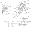
- As shown in
Figure 1 , an espresso machine with built-in coffee grinder comprises a base 10 that supports a carriage within which is contained a drip tray with cover and a concealed storage tray. An upright portion 11 extends from thebase 10 and supports aledge 12. The underside of the ledge features aremovable tamper 13, aportafilter support cradle 14 that is located below an internal coffee grinder and the group head orbrew head 15. The front face of the ledge comprisesvarious user controls 16, apressure gauge 17 andvarious indicators 18. A removable bean hopper 19 discharges beans into the internal grinder. Aninternal microprocessor 20 receives the various user inputs and operational parameters produced by the machine's internal sensors and using these, controls the operation of the grinder, indicators and the machine's boiler, hot water and steam systems. - As shown in
Figure 2 the user operated grind controls include a variable dosestrength adjustment knob 21 and adose toggle switch 22. The dose strength adjustment knob is in this example a variable resistor with 11 discreet settings. In this example, settings are communicated to a microprocessor that uses the settings to control the operation of the built-in grinder's electrical motor. Each of the discreet or continuous settings determined by thestrength adjustment knob 21 corresponds to a duration of operation of the grinder. In effect, less operation time means less grinds and thus weaker coffee and longer operation of the grinder results in more coffee being delivered to the portafilter and thus a stronger brew. It will be appreciated that, for example, a linear resistor may be used in place of a rotary one and digital controls may be employed in more sophisticated examples. - The
dose toggle switch 22 toggles between single cup and double cup dose settings. Thetoggle switch 22 is associated with, for example, twoindicators indicators single cup dose 23 ordouble cup dose 24 has been selected by the user operating thedose toggle switch 22. - The micro processor that is controlled by the dose strength adjustment setting 21 will apply the strength adjustment setting to both the single and double cup dose time settings that are used to control the grinder. Accordingly, operation of the strength adjustment setting 21 while the
toggle 22 is set for a single cup dose will result in a comparable dose adjustment being automatically made when the toggle is changed to a double cup dose. Similarly, strength adjustments made when the toggle is set for a double cup are remembered by the microprocessor and applied appropriately to single cup doses. The microprocessor applies an algorithm or get stored values from, for example, a look-up table or the like. - The dose strength adjustment setting 21 is desirable for at least two different reasons. First, normal manufacturing tolerances within the machine's coffee grinding heads result in differences in the outputs of different machines. The dose strength adjustment allows this inconsistency to be rectified with a relatively simple user adjustment. Further, the grind size is determined by, for example, the distance between the burrs and the grinder and because this distance is user adjustable, adjustments in the duration of the operation time of the grinder are required to compensate for the variation in grind size setting. For example, coarser grinds will provide a greater output (by weight) for a given operating time than when set to a finer grind. That is, finer particles take longer to grind. Enough range is provided in the
dose strength adjustment 21 to deal with the full range of user selectable grind size settings. - As shown in
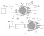
Figure 3 , theportafilter 30 is retained by a fillingcradle 31 while fresh grinds from the grinder are being dispensed into it. Thecradle 31 comprises a "U" shaped receiving opening 32 flanked by a symmetrical pair ofwings 33. An upper surface 34 of the cradle Is formed with a dispensingopening 35 that cooperates with a generally "U" shapedguide channel 36 that leads grinds toward the portafilter's filter basket (not shown inFigure 3 ). Theportafilter 30 has circularupper periphery 37 for receiving the filter basket. Theupper periphery 37 is surrounded by, for example, three equally spacedtabs 38. Thetabs 38 are used to engage the portafilter with the brew head during brewing operations. The brew head has helical slots that receive the tabs and which promote sealing of the filter basket against the underside of the group head when the portafilter is rotated into its final or brewing position. - The
tabs 38 are also used to support the portafilter in a hands free manner while ground coffee is being dispensed into it. As shown InFigures 4- 8 , the rear tabs, being the ones closest to the portafilter's handle are supported bytapered ledges 39 that extend from the lower extremity of thewings 33. Theledges 39 taper from a maximum width toward the front of the cradle to a minimum width at the rear or deepest part of the cradle opening 32. As shown inFigure 6 , the tworear tabs 61, 62 are at least partially if not fully supported by theledge 39 when the portafilter is inserted into thecradle 31. In this orientation, thefront tab 63 is adjacent to a reciprocating actuator 64 that cooperates with an electrical switch such as a microswitch. The actuator 64 has a curved front surface 65 that cooperates with thefront tab 63. The actuator 64 fits within and slides relative to anopening 66 formed in the cradle between thewings 31. As shown inFigure 7 , theportafilter 30 may be advanced against the actuator 64 so that the actuator's switch can be operated in this way. - In a preferred embodiment, advancing the
portafilter 30 against the actuator 64 (momentarily) and then releasing it sends a signal to the microprocessor that causes an automatic filling of the filter basket by actuating the grinder for a specified or preset time. This time depends on the setting of the dose strength adjustment setting 21 and thedose toggle switch 22. Pressing the front tab 64 of the portafilter against the actuator 64 and holding it continuously in the position depicted inFigure 7 causes the microprocessor to operate the grinder until pressure on the actuator 64 is released manually or a predetermined operating time for the grinder is reached. - The
rear tabs 61, 62 of the portafilter, when resting on theledges 39 of thewings 31 act as a pivot point. The weight of the portafilter'shandle 30a causes an imbalance that is resisted by an internal downward facingledge 41 formed above thefront tab 42 when it is inserted into thecradle 31. In this way, the imbalance caused by the weight of the handle is resisted and the portafilter remains stable in the cradle, even when the user is not holding it in place. - As shown in
Figures 3 and9 , the dispensingopening 35 of the cradle includes an arcuate orcurved rim portion 45. This curved portion of theopening 35 is located toward the front of the filter basket when the portafilter is inserted into the cradle. Thecurved portion 45 of theopening 35 cooperates with thecurved guide channel 46 so that grounds are deposited toward the front half 91 of the filter basket rather than the rear half 92. These features contribute to the stability of the mound formed by the dispensed grinds, making spilling less likely. - As shown in
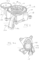
Figure 11 , the espresso machine contains aninternal coffee grinder 110. Thegrinder 110 comprises an upper burr 111, a lower burr 112, a motor andgearbox case arrangement 113, a user grind size adjustment mechanism and a dispensingchute 115. In this example, a conical burr grinder is used. Thus, the lower burr 112 is rotated by the motor and its gearbox with respect to the stationery upper burr head 111. The upper burr head ill is removably retained by anupper burr bracket 116. Theupper burr bracket 16 locates the removable upper burr head in a predictable and repeatable way relative to the fixed lower burr head 112. The upper burr head ill is retained in theupper burr bracket 116 by a retaining ring 117 that carries afolding grip 118 that can be deployed and twisted so as to free the ring 117 from thebracket 116 allowing the upper burr head to be removed, maintained or replaced. The entire upper burr bracket may be rotated and thus displaced from the lower burr by a firstadjustment gear ring 119. Thisgear ring 119 is rotated by a smaller orsecond adjustment gear 120 carried on the underside of auser adjustment dial 121. The user adjustment dial and itssecond gear 120 are supported for rotation by the housing of the motor and gearbox. Thus, rotation of theadjustment dial 121 causes a linear displacement of the upper burr bracket and hence the upper burr 111. The closer the upper burr head ill is to thelower burr head 120, the finer the grinds that are created. As shown inFigure 12a , the receivingcavity 125 located below the burrs of the grinder features anexit opening 126. This exit opening 126 leads into aconstriction area 127 that extends between thedischarge opening 126 and the opening into the dispensingchute 115. In some embodiments, theconstriction area 127 has parallel side walls that are configured to gently compress rather than disperse the grind particles. This light compression of the particles reduces the velocity and volume of the discharge and reduces the accumulation of static electricity in the particles and their interaction with thepolymeric chute 115. Thus, grinds are discharged in a more compressed or compact way into the filter basket of the portafilter. This minimises the amount of spillage from the filter basket. - As shown in
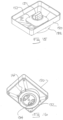
Figure 12b , the motor, gearbox and part of the conical burr grinding assembly are contained within aunitary case 113. An upper portion of that case contains arecess 113a for receiving the lower burr 112. A discharge orexit opening 126 is formed into a side wall of therecess 113a. Thecase 113 also contains journal support structures 113b for supporting theuser adjustment dial 121 and any gear train associated with it. - As shown in
Figure 12c , the ground coffee particles circulate within thecasing 113 until such time as they enter theconstriction area 127 prior to discharge from the taperedchute 115. Note thatchute 115 terminates in a generally "D" shaped port 115a that cooperates with the configuration and shape of the dispensingopening 35 formed in the filling cradle 31 (seeFigure 3 ). With reference toFigure 11 , it can also be appreciated that thechute 115 is provided with aremovable cover 115b that is attached by clips 115c, allowing the interior of the chute to be accessed for cleaning or maintenance. - As shown in
Figure 12d , the upper burr head 111 is removably retained by theupper burr bracket 116. In this example, thebracket 116 contains male internal bayonet features 166a that cooperate withfemale bayonet features 117a formed around the external circumference of the upper burr head 111. This allows for a positive mechanical engagement that is repeatable and predictable, facilitating the removal and reinsertion of the upper burr head ill into itsburr bracket 116. - As shown in
Figures 13-16 , the espresso machines internal grinder is supplied with coffee beans from a removable,external hopper 150. Thehopper 115 comprises abean reservoir 131, acoupling portion 132, a coupling mechanism and an optionaltransparent cover 141. - In this example, the
coupling portion 132 is generally cylindrical and fits within a cooperating opening formed on an upper portion of an espresso machine. The receiving opening for the coupling portion 32 includes a pair of recesses for receivingreciprocating sliders 161 that extend radially from the cylindrical side walls of thecoupling portion 132. As shown inFigure 13 , the underside 133 of thecoupling portion 132 has one ormore discharge openings 134 that can be blocked by a rotating shutter. The shutter is operated by adial 151 that extends through acover 152 within thereservoir 131. Rotating thedial 151 closes the shutter and simultaneously causes the safety sliders 162 to retract into thecoupling portion 132. Retraction of thesliders 161 from the cooperating openings in the receiving portion of the espresso machine allows the hopper to be withdrawn, the shutter having already been closed to prevent beans from being inadvertently discharged. Retraction of the sliders from their cooperating openings in the espresso machine also deactivates an electrical switch associated with one or both receiving openings which has the effect of de-energising or locking out the power supply to the grinder's motor, thus rendering the grinder inoperative until such time as the hopper is reinstalled and the dial is twisted. Installation of the hopper by twisting the dial causes the sliders to extend and thus rendered the grinder's motor operative. This arrangement is a safety feature that prevents the grinder's motor from being operated unless the hopper is securely in place. - As shown in
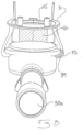
Figures 17 and 18 , an upper portion of the espresso machine features, for example, atop cover 170 having a recess 171 for receiving the body of the hopper andopening 172 for receiving the coupling portion of the hopper. The recess 71 features a pair of openings orsleeves 173 for receiving the sliders. As shown inFigure 18 , amicroswitch 181 is mounted under the cover, adjacent to one or both of the receivingopenings 173. Themicroswitch 181 cooperates with the espresso machines micro processor for the purpose of disabling the grinder's motor once the sliders are retracted. - As shown in
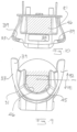
Figures 19 and 20 , thechassis 191 of the espresso machine supports aremovable coffee tamper 192. In this example, thechassis 191 includes afrontal overhanging ledge 193. Theledge 193 hasopenings 194, 195 for receiving relevant portions of the machine's grinder and group head. The underside of theledge 193 also features atapered recess 196 for receiving aremovable tamper 192. Thetamper 192 has an elongated handle 197 that is tapered to cooperate snugly with the receivingrecess 196. Amagnet 198 is located in association with therecess 196 and preferably on or adjacent to the uppermost extremity of therecess 196. Thecoffee tamper 192 features ametallic cap 200 that is attracted by the magnet and assists in retaining the tamper within therecess 196. Thetamper 192 has an enlarged head 201 that is used to compress ground coffee into the filter basket. It can be used in the orientation depicted inFigures 19 and 20 , that is, inserted into the recess. In the alternative, it can be removed and reinserted 202, at will, by the user. In preferred embodiments, the tamper and its recess are located conveniently adjacent to the coffee grinds dispenser, as indicated by the relationship between therecess 196 and the opening in the chassis for the grinder 194 shown inFigure 19 . - The espresso machine also supports a removable drip tray and drip tray cover as shown in
Figures 21 - 23 . The cover may be located under a grille (not shown). As shown inFigure 21 , thedrip tray 210 comprises afacia 211,side walls 212 and arear wall 213 that define aliquid receptacle 214. Thereceptacle 214 has a cooperatingdrip tray cover 215. Thecover 215 has adepressed area 216, the floor of which is perforated 217. The perforations are preferably tapered, having a larger diameter at theundersurface 231 and smaller diameter at theupper surface 218 of the drip tray cover. The perforations are adapted to trap coffee grinds above the tray, not letting an excessive amount of grinds into thereceptacle 214. Thus, liquids trapped in thereceptacle 214 can be disposed of in a kitchen sink without discharging an excessive amount of grinds into the sink. Thedepressed area 216 is subdivided by a barrier orwall 219. Waste grinds associated with the coffee grinder and tamper generally fall to the left of the wall 19 because the grinder and tamper are located to the left of and above this wall. The brew head is located to the right of and above the wall 219 (seeFigure 1 ). Thus, theperforated floor 220 on the right hand side of thewall 219 features one or morelarger openings 221 that allowed brewed coffee waste to more easily flow into thereceptacle 214. The tray also features a receptacle level indicator 222 that can be read through anopening 223 formed in the cover, in registry with the indicator 222. - As shown in
Figure 23 thedrip tray 210 slides into and out of a receivingcarriage 230 that is fixed with respect to the espresso machine and preferably located at a lowermost portion orbase 10 of the espresso machine. Thedrip tray 210 is adapted forreciprocal motion 231 relative to thecarriage 230. As shown inFigure 23 , therear wall 213 of the drip tray has arear surface 232 from which extends a hook feature orupturned lip 233. Theupturned lip 233 is adapted to receiving a hook feature or cooperatingdownturned lip 234 formed on an exterior of a side wall of astorage tray 234. Thestorage tray 234 is also adapted for reciprocal sliding motion within thestationery carriage 230. As shown inFigure 23 , both thestorage tray 234 and thedrip tray 210 are fully inserted into thecarriage 230. In this orientation, the perforated portion of the drip tray is generally exterior to an adjacent externalfront surface 235 of the espresso machine. Thus, thestorage tray 234 and the rear of the drip tray are concealed behind thefront surface 235. In this orientation, the depressed, perforated area of the drip tray cover (seeFigure 21 ) is external to the before mentionedsurface 235, but the remainder of the drip tray and its cover, together with thestorage tray 234 are effectively concealed within the espresso machine. - A one or more small bumps, protrusions or raised
lip 240 is formed into the upper surface of thefloor 241 of thecarriage 230. Theprotrusion 240 is external to thefront surface 235 of the espresso machine. During itsreciprocal motion 231, the underside of the drip tray does not contact theprotrusion 240 however, because the drip tray and the storage tray are interconnected by the hook-like features Figure 24 , thestorage tray 234 will eventually be carried forward by the drip tray (not shown) until a forwardlower edge 241 of the storage tray contacts theprotrusion 240. This will cause the front of thestorage tray 234 to rise or lift relative to theupturned lip 233 of the drip tray. Thus, upon contract with theprotrusion 240, the storage tray becomes disconnected or decoupled from the drip tray at approximately the time that itsfront edge 243 protrudes externally of the adjacentfront surface 235 of the espresso machine. This makes full removal of the concealable storage tray by the user easy. Repositioning of the storage tray into the carriage and urging it toward the rear of the carriage using the drip tray causes the hook-like features -
Figure 25 illustrates a cross sectional detail of the perforations found on thedrip tray cover 215, particularly in thedepressed area 216 provided in the example depicted inFigures 21 - 23 . As shown inFigure 25 thecircular perforations 250 are tapered 251 having thesmaller diameter 252 on theupper surface 253 and the larger diameter on thelower surface 254. In this example, thehole diameter 255 at the upper surface is about 2.2mm. The rim of the upper opening may be radiused. As illustrated in this example, the taper is a downward opening taper of approximately 20degrees 256. - While the present invention has been disclosed with reference to particular details of construction, these should be understood as having been provided by way of example and not as limitations to the scope spirit of the invention.
- Examples of the present invention include:
- Example 1: In an espresso machine with a built in coffee grinder, the improvement comprising: a filling cradle for holding a portafilter; the cradle comprising a generally U shaped opening for receiving the portafilter in a hands free manner while grounds are dispensed into it.
- Example 2: The espresso machine of example 1, wherein the cradle is adjacent to an actuator that cooperates with the portafilter when the portafilter is in the cradle; the actuator causing a signal to be sent to a microprocessor when it is activated by the portafilter; the signal causing coffee grounds to be dispensed into the portafilter.
- Example 3: The espresso machine of example 2, wherein the signal causes the grinder to operate for a predetermined time.
- Example 4: The espresso machine of example 1, wherein the portafilter is supported against imbalanced pivoting in the cradle by a downward facing ledge formed adjacent to the cradle.
- Example 5: The espresso machine of example 1, wherein the cradle has a dispensing opening located toward a front of a filer basket of the portafilter, the opening causing grounds to be deposited toward a front half of the filter basket, thus contributing to the stability of a mound formed by the grounds.
- Example 6: The espresso machine of example 1, wherein the portafilter has tabs for engaging the brew head; the tabs including a front tab; the front tab serving to act against the actuator.
- Example 7: In an espresso machine with a built in coffee grinder, the improvement comprising: a user operated variable coffee dose adjustment and a dose toggle; the user operated variable coffee dose adjustment sending a first signal to a microprocessor; the dose toggle sending a second signal to the microprocessor that is indicative of a user requirement for either one or two doses; the microprocessor using the first and second signals to determine a duration of operation of the grinder.
- Example 8: The espresso machine of example 7, wherein the dose toggle is associated with an indicator that indicates wether a single cup or double cup dose has been selected.
- Example 9: The espresso machine of example 7, wherein the microprocessor will apply the first signal and deliver a comparable dose per cup when the dose toggle is changed from one to two doses.
- Example 10: The espresso machine of example 7, wherein the grinder is adapted to deliver a user selectable variable grind size.
- Example 11: The espresso machine of example 7, wherein the grinder is a conical burr grinder.
- Example 12: The espresso machine of example 7, wherein the grinder is a burr grinder and an upper burr head is retained by a bracket that allows the upper burr head to be removed and replaced in a repeatable way relative to a lower burr head.
- Example 13: In an espresso machine with a built in coffee grinder, the improvement comprising: a removable hopper comprising a bean reservoir and a coupling portion; the coupling portion adapted to fit within a cooperating receiving opening formed on the espresso machine; the receiving opening including at least one recess for receiving a reciprocating slider that extends from a side wall of the coupling portion; an underside of the coupling portion having one or more discharge openings that can be blocked by a shutter; operation of a user contol closing the shutter and simultaneously causing the slider to retract allowing the hopper to be withdrawn.
- Example 14: The espresso machine of example 13, wherein retraction of the slider also deactivates an electrical switch associated with the receiving opening; the switch locking out a power supply to a motor that drives the grinder, thus rendering the grinder inoperative until such time as the hopper is installed.
- Example 15: The espresso machine of example 13, wherein there are two opposing sleeves for receiving the slider and a second slider; the switch being a microswitch mounted adjacent to at least one of the sleeves.
- Example 16: The espresso machine of example 13, wherein the shutter is a rotating shutter.
- Example 17: The espresso machine of example 13, wherein the slider retracts into the coupling portion.
Claims (12)
- A method of using a removable tamper supported by a chassis of an espresso machine, the method comprising:removing the tamper from a recess formed in the chassis, wherein a magnet is associated with the recess;compressing ground coffee by the tamper; andreinserting the tamper in the recess,wherein the tamper comprises a metallic cap and the magnet is arranged to retain the tamper within the recess.
- The method of claim 1, wherein the tamper includes an elongated handle, the elongated handle being shaped to cooperate with the recess.
- The method of claim 1 or 2, wherein the recess is located adjacent to a coffee grinds dispenser of a grinder mounted in the chassis.
- The method of any one of claims 1-3, wherein the magnet is located adjacent an upper portion of the recess.
- The method of any one of claims 1-4, wherein the magnet is located in the recess.
- The method of any one of claims 1-5, wherein a front portion of the chassis includes a ledge, the ledge including an underside; and
wherein the recess is formed in the underside of the ledge. - An espresso machine comprising:a removable tamper comprising a metallic cap;a chassis;a recess formed in the chassis and sized to removably receive the tamper; anda magnet associated with the recess, the magnet arranged to retain the tamper in the recess.
- The espresso machine of claim 1, wherein:a front portion of the chassis includes an overhanging ledge, the ledge including an underside; andwherein the recess is formed in the underside of the ledge.
- The espresso machine of claim 7 or 8, wherein the tamper includes an elongated handle, the elongated handle being shaped to cooperate with the recess.
- The espresso machine of any one of claims 7-9, wherein the magnet is located adjacent an upper portion of the recess.
- The espresso machine of any one of claims 7-10, wherein the magnet is located in the recess
- The espresso machine of any one of claims 7-11, wherein the recess is located adjacent to a coffee grinds dispenser of a grinder mounted in the chassis.
Applications Claiming Priority (3)
| Application Number | Priority Date | Filing Date | Title |
|---|---|---|---|
| AU2009900315A AU2009900315A0 (en) | 2009-01-29 | Espresso Machine with Grinder Dosing Control | |
| EP10735432.6A EP2391250B1 (en) | 2009-01-29 | 2010-01-29 | Espresso machine with grinder dosing control |
| PCT/AU2010/000087 WO2010085850A1 (en) | 2009-01-29 | 2010-01-29 | Espresso machine with grinder dosing control |
Related Parent Applications (2)
| Application Number | Title | Priority Date | Filing Date |
|---|---|---|---|
| EP10735432.6A Division EP2391250B1 (en) | 2009-01-29 | 2010-01-29 | Espresso machine with grinder dosing control |
| EP10735432.6A Division-Into EP2391250B1 (en) | 2009-01-29 | 2010-01-29 | Espresso machine with grinder dosing control |
Publications (1)
| Publication Number | Publication Date |
|---|---|
| EP4197404A1 true EP4197404A1 (en) | 2023-06-21 |
Family
ID=42395054
Family Applications (2)
| Application Number | Title | Priority Date | Filing Date |
|---|---|---|---|
| EP22207842.0A Pending EP4197404A1 (en) | 2009-01-29 | 2010-01-29 | Espresso machine with grinder dosing control |
| EP10735432.6A Active EP2391250B1 (en) | 2009-01-29 | 2010-01-29 | Espresso machine with grinder dosing control |
Family Applications After (1)
| Application Number | Title | Priority Date | Filing Date |
|---|---|---|---|
| EP10735432.6A Active EP2391250B1 (en) | 2009-01-29 | 2010-01-29 | Espresso machine with grinder dosing control |
Country Status (7)
| Country | Link |
|---|---|
| US (1) | US20110283889A1 (en) |
| EP (2) | EP4197404A1 (en) |
| CN (2) | CN102325485B (en) |
| AU (2) | AU2010207886A1 (en) |
| DE (1) | DE202010018613U1 (en) |
| RU (2) | RU2555800C2 (en) |
| WO (1) | WO2010085850A1 (en) |
Families Citing this family (46)
| Publication number | Priority date | Publication date | Assignee | Title |
|---|---|---|---|---|
| MX2011007934A (en) * | 2009-02-01 | 2011-09-30 | Espresso Corp Ltd | Wastage reducing device. |
| EP2544571B8 (en) * | 2010-03-12 | 2018-11-07 | Breville PTY Limited | Conical burr grinder |
| US10240969B2 (en) | 2011-04-05 | 2019-03-26 | Mazzer Luigi S.P.A. | Portafilter and grounds weighing platform system and methods of use |
| US8936017B2 (en) | 2011-05-09 | 2015-01-20 | Max Alejandro Holdo Baggott | Cooking apparatus with downward opening lid |
| NL2007126C2 (en) * | 2011-07-18 | 2013-01-21 | Barista Technology B V | Ground coffee pressing device. |
| AU2012238276A1 (en) * | 2011-10-04 | 2013-04-18 | Sunbeam Corporation Limited | Beverage appliance filter assembly with control input |
| AU2012268779B2 (en) * | 2011-12-20 | 2015-10-01 | Newell Australia Pty Ltd | Dispensing appliance |
| CH706100A1 (en) * | 2012-02-08 | 2013-08-15 | Wmf Wuerttemberg Metallwaren | Coffee grinder and removable filter holder and method for operating such a coffee maker. |
| ITMI20120768A1 (en) * | 2012-05-08 | 2013-11-09 | Corte Paolo Dalla | SYSTEM AND METHOD OF DISTRIBUTION OF ESPRESSO COFFEE |
| DE202012102131U1 (en) * | 2012-06-12 | 2013-09-18 | Eugster/Frismag Ag | coffee machine |
| ITPN20120050A1 (en) * | 2012-09-07 | 2014-03-08 | Cma Macchine Per Caffe S R L | AUTOMATIC COFFEE MACHINE ¿FOR PREPARATION OF COFFEE uro EXPRESS |
| ITBS20130037A1 (en) * | 2013-03-21 | 2014-09-22 | Bsh Italia S R L | COFFEE MACHINE' |
| US10709287B2 (en) | 2013-04-02 | 2020-07-14 | Koninklijke Philips N.V. | Beverage-producing machine with single slide actuator for locking hopper and opening ingredient aperture therein |
| USD742169S1 (en) * | 2013-10-07 | 2015-11-03 | Breville Pty Limited | Espresso making machine |
| JP6214411B2 (en) * | 2014-01-31 | 2017-10-18 | シャープ株式会社 | Beverage production equipment |
| US20160070403A1 (en) * | 2014-09-08 | 2016-03-10 | Aliphcom | Wearable pods and devices including metalized interfaces |
| ITUB20154744A1 (en) * | 2014-11-20 | 2017-04-23 | Nuova Simonelli S P A | PERFECT COFFEE MILL MACHINE. |
| US11241115B2 (en) * | 2014-12-18 | 2022-02-08 | Societe Des Produits Nestle S.A. | Beverage machine with slidingly connectable cup-support |
| US9675211B2 (en) * | 2015-03-06 | 2017-06-13 | Helen Of Troy Limited | No-bean detection for coffee bean grinder |
| CN105534313B (en) * | 2015-04-28 | 2019-03-19 | 周林斌 | Grind the crushing filter device of bean coffee pot machine |
| CN106913217A (en) * | 2015-12-24 | 2017-07-04 | 威斯达电器(中山)制造有限公司 | Bean milling device and the automatic coffee pot with the bean milling device |
| TWM521433U (en) * | 2016-02-17 | 2016-05-11 | Chouki Internat Company Ltd | Brewing material grinder |
| CN105615662B (en) * | 2016-02-29 | 2018-08-14 | 宁波全景电器技术有限公司 | A kind of quantity of coffee gearshift of coffee machine |
| KR101757271B1 (en) * | 2016-03-10 | 2017-07-12 | (주)커피 리브레 | Coffee grinding apparatus |
| WO2017205900A1 (en) * | 2016-06-02 | 2017-12-07 | Invento Pty Ltd | A coffee dispenser |
| IT201600122741A1 (en) * | 2016-12-02 | 2018-06-02 | Gruppo Cimbali Spa | Equipment for pressing a dose of coffee into the filter holder. |
| IT201700058749A1 (en) * | 2017-05-30 | 2018-11-30 | De Longhi Appliances Srl | Coffee machine equipped with a grinder and a procedure for controlling the grinder of the coffee machine |
| US11006779B2 (en) | 2017-07-11 | 2021-05-18 | Nubru, Llc | Method and apparatus for improving the consistency of espresso shots |
| IT201700090275A1 (en) * | 2017-08-03 | 2019-02-03 | De Longhi Appliances Srl | DEVICE FOR PRESSING A DOSE OF GROUND POWDER COFFEE |
| EP3675693A4 (en) * | 2017-08-31 | 2021-08-04 | Innovative Brewing, LLC | Devices and methods for brewing beverages |
| IT201700104696A1 (en) * | 2017-09-19 | 2019-03-19 | B M Laser S R L | COFFEE GRINDING AND PRESSING DEVICE |
| IT201800002956A1 (en) * | 2018-02-22 | 2019-08-22 | Fiorenzato M C Srl | SELF METHOD - INSTANT CALIBRATION OF THE DOSE FOR A COFFEE GRINDER-DOSING DEVICE |
| US11503955B2 (en) * | 2018-11-08 | 2022-11-22 | Whirlpool Corporation | Coffee grinding apparatus with portafilter holder assembly |
| US20200146508A1 (en) * | 2018-11-08 | 2020-05-14 | Whirlpool Corporation | Coffee grinding apparatus with portafilter holder assembly |
| DE102019134919A1 (en) | 2019-12-18 | 2021-06-24 | Franke Kaffeemaschinen Ag | Beverage preparation device with outlet device |
| DE102020121288B3 (en) * | 2020-08-13 | 2021-04-29 | AVS, Ingenieur J.C. Römer GmbH | Portafilter, connection section for a portafilter and coffee maker |
| CN116322443A (en) * | 2020-10-22 | 2023-06-23 | 德龙电器有限责任公司 | Coffee grind apparatus comprising a detachable fitment for containing a dispersion of coffee grounds |
| WO2022133542A1 (en) * | 2020-12-23 | 2022-06-30 | Breville Pty Limited | A machine and tamping mechanism |
| DE102021102743B3 (en) | 2021-02-05 | 2022-07-07 | Next Level Coffee GmbH | Automatically adjustable coffee machine and associated coffee bean container |
| US11647865B2 (en) | 2021-03-05 | 2023-05-16 | Srategic Exits LLC | Conical burr hand grinder |
| USD935832S1 (en) | 2021-03-05 | 2021-11-16 | Strategic Exits LLC | Coffee grinder |
| DE102021108202A1 (en) | 2021-03-31 | 2022-10-06 | Franke Kaffeemaschinen Ag | beverage preparation device |
| USD945816S1 (en) | 2021-04-22 | 2022-03-15 | Strategic Exits LLC | Coffee grinder |
| WO2023115097A1 (en) * | 2021-12-22 | 2023-06-29 | Breville Pty Limited | A coffee machine with a grinder |
| EP4230097A1 (en) | 2022-02-17 | 2023-08-23 | BSH Hausgeräte GmbH | Coffee machine |
| US20230371736A1 (en) * | 2022-04-01 | 2023-11-23 | Meticulous Home, Inc. | System and methods for automated brew cycles and machine controls and interfaces |
Citations (3)
| Publication number | Priority date | Publication date | Assignee | Title |
|---|---|---|---|---|
| CH660288A5 (en) * | 1984-07-13 | 1987-04-15 | Omre Srl | Automatic espresso coffee machine |
| EP0245197A2 (en) * | 1986-05-05 | 1987-11-11 | Cafina AG | Method for making coffee |
| EP0312901A1 (en) * | 1987-10-23 | 1989-04-26 | Micromax International S.r.l. | An automatic espresso coffee making machine for household use |
Family Cites Families (38)
| Publication number | Priority date | Publication date | Assignee | Title |
|---|---|---|---|---|
| DE1299383B (en) * | 1967-07-01 | 1969-07-17 | Bosch Hausgeraete Gmbh | Coffee grinder with an electric drive and a timer that serves as a dosing device |
| US3791284A (en) * | 1971-01-29 | 1974-02-12 | G Donot | Machine for making coffee beverage |
| DE3400567C3 (en) * | 1984-01-10 | 1994-07-28 | Krups Fa Robert | Electrically operated espresso machine |
| US4852474A (en) * | 1986-09-24 | 1989-08-01 | Robert Krups Stiftung & Co. Kg | Espresso machine with cappuccino making attachment |
| FR2610502B1 (en) * | 1987-02-11 | 1991-02-08 | Levi Mario | A DETECTION AND DISPLAY DEVICE FOR AN AUTOMATIC EXPRESS COFFEE MACHINE |
| DE3843568C1 (en) * | 1988-12-23 | 1989-12-21 | Hgz - Maschinenbau Ag, Daellikon, Zuerich, Ch | |
| US5650186A (en) * | 1993-06-07 | 1997-07-22 | Annoni; Faust | Hot beverage brewing and dispensing apparatus and method |
| DE29502596U1 (en) * | 1995-02-17 | 1995-04-06 | Eugster Arthur Ag | Coffee machine with integrated coffee grinder |
| IT1280833B1 (en) * | 1995-03-31 | 1998-02-11 | Enrico Marogna | DEVICE FOR CONTROL OF COFFEE GRINDING, GRINDER DOSING MACHINE EQUIPPED WITH THIS DEVICE AND PROCEDURE FOR THE |
| IT237195Y1 (en) * | 1995-10-05 | 2000-09-05 | Il Caffe Del Professore S R L | ELECTRONIC APPARATUS FOR COFFEE GRINDING AND Dosing |
| ES2147657T3 (en) * | 1995-12-28 | 2000-09-16 | Creaholic Sa | COFFEE MAKER. |
| US6095032A (en) * | 1998-11-06 | 2000-08-01 | La Marzocco International L.L.C. | Coffee grinding, portioning, and pressing device |
| JP2003506107A (en) * | 1999-08-14 | 2003-02-18 | ザ プロクター アンド ギャンブル カンパニー | Method and system for using delayed filtration to provide a variety of customized freshly brewed coffee on demand |
| IN192798B (en) * | 2000-03-15 | 2004-05-22 | Fianara Int Bv | |
| US6581511B2 (en) * | 2001-02-16 | 2003-06-24 | Romar Llc | Multi-reservoir automatic dispenser system |
| US6357345B1 (en) * | 2001-02-16 | 2002-03-19 | Romar Llc | Multi-reservoir automatic dispenser system |
| AU2002258544A1 (en) * | 2001-03-16 | 2002-10-03 | The Procter And Gamble Company | Beverage brewing devices for preparing creamy beverages |
| US6572036B2 (en) * | 2001-04-20 | 2003-06-03 | Appliance Development Corporation | Coffee grinder with storage and dispensing means |
| US6700340B2 (en) * | 2002-03-19 | 2004-03-02 | Hamilton Beach/Proctor-Silex, Inc. | Control circuit for a coffee grinder |
| EP1393663B1 (en) * | 2002-08-29 | 2006-11-29 | Jura Elektroapparate Ag | Coffee machine with a manually operated cover of a filling opening for special coffee and method for controlling the position of this cover |
| CA2490500A1 (en) * | 2003-12-18 | 2005-06-18 | Espro Inc. | Calibrated handheld espresso tamper |
| DE602004027160D1 (en) * | 2003-12-27 | 2010-06-24 | Torben Malykke | AUTOMATIC DOSING UNIT |
| MY138658A (en) * | 2004-02-20 | 2009-07-31 | Nestec Sa | System for dispensing short and long coffee beverages |
| DE202004018776U1 (en) * | 2004-12-04 | 2005-02-10 | Eugster/Frismag Ag | Brewing head of an espresso machine |
| EP1676509A1 (en) * | 2004-12-30 | 2006-07-05 | Rhea Vendors S.p.A. | Process and apparatus for controlling the preparation of brewed beverages |
| US20060150822A1 (en) * | 2005-01-13 | 2006-07-13 | Chien-Wen Wu | Method for making espresso and device for the like |
| AU2006217656A1 (en) * | 2005-02-28 | 2006-08-31 | Coffee Nation Ltd. | Apparatus for preparing beverages |
| WO2007027206A2 (en) * | 2005-04-11 | 2007-03-08 | Coffee Equipment Company | Machine for brewing a beverage such as coffee and related method |
| WO2006133699A2 (en) * | 2005-06-14 | 2006-12-21 | Torben Malykke | Automatic dosage unit |
| NZ541321A (en) * | 2005-07-19 | 2007-09-28 | Fonterra Co Operative Group | System for dispensing a customised serving based on user requirements and nutritional considerations |
| ITVE20050061A1 (en) * | 2005-12-13 | 2007-06-14 | Macap S R L | MANUAL PRESS |
| RU2314738C2 (en) * | 2006-01-18 | 2008-01-20 | Евгений Анатольевич Логунов | Coffee generator |
| US7927642B2 (en) * | 2006-02-23 | 2011-04-19 | Carl James Campetella | Method for making coffee with a crema layer |
| FR2900811B1 (en) * | 2006-05-09 | 2008-08-22 | Seb Sa | AUTOMATIC DISPENSER OF INFINED BEVERAGES |
| CN201001639Y (en) * | 2007-03-06 | 2008-01-09 | 万事达(杭州)咖啡机有限公司 | Pouring device for full automatic coffee making machine |
| KR200440510Y1 (en) * | 2007-04-12 | 2008-06-16 | (주)닥터로빈 | Tamper |
| US7874505B1 (en) * | 2007-08-31 | 2011-01-25 | Food Equipment Technologies Company, Inc. | Food grinder with electronically adjustable grind settings, tooless disassembly |
| NL2007126C2 (en) * | 2011-07-18 | 2013-01-21 | Barista Technology B V | Ground coffee pressing device. |
-
2010
- 2010-01-29 EP EP22207842.0A patent/EP4197404A1/en active Pending
- 2010-01-29 EP EP10735432.6A patent/EP2391250B1/en active Active
- 2010-01-29 DE DE202010018613.7U patent/DE202010018613U1/en not_active Expired - Lifetime
- 2010-01-29 AU AU2010207886A patent/AU2010207886A1/en not_active Abandoned
- 2010-01-29 CN CN201080008807.XA patent/CN102325485B/en active Active
- 2010-01-29 RU RU2011135818/12A patent/RU2555800C2/en active
- 2010-01-29 US US13/145,777 patent/US20110283889A1/en not_active Abandoned
- 2010-01-29 WO PCT/AU2010/000087 patent/WO2010085850A1/en active Application Filing
- 2010-01-29 CN CN201510500733.6A patent/CN105054791B/en active Active
-
2015
- 2015-02-09 RU RU2015104155A patent/RU2680420C2/en active
-
2016
- 2016-06-09 AU AU2016203881A patent/AU2016203881B2/en active Active
Patent Citations (3)
| Publication number | Priority date | Publication date | Assignee | Title |
|---|---|---|---|---|
| CH660288A5 (en) * | 1984-07-13 | 1987-04-15 | Omre Srl | Automatic espresso coffee machine |
| EP0245197A2 (en) * | 1986-05-05 | 1987-11-11 | Cafina AG | Method for making coffee |
| EP0312901A1 (en) * | 1987-10-23 | 1989-04-26 | Micromax International S.r.l. | An automatic espresso coffee making machine for household use |
Also Published As
| Publication number | Publication date |
|---|---|
| RU2015104155A (en) | 2016-08-27 |
| RU2680420C2 (en) | 2019-02-21 |
| AU2016203881A1 (en) | 2016-06-30 |
| EP2391250A4 (en) | 2014-05-21 |
| DE202010018613U1 (en) | 2018-08-23 |
| RU2011135818A (en) | 2013-03-10 |
| CN102325485B (en) | 2015-09-09 |
| AU2010207886A1 (en) | 2011-08-11 |
| EP2391250B1 (en) | 2023-01-18 |
| RU2555800C2 (en) | 2015-07-10 |
| CN102325485A (en) | 2012-01-18 |
| AU2016203881B2 (en) | 2018-02-15 |
| CN105054791A (en) | 2015-11-18 |
| EP2391250A1 (en) | 2011-12-07 |
| WO2010085850A1 (en) | 2010-08-05 |
| RU2015104155A3 (en) | 2018-07-31 |
| CN105054791B (en) | 2018-07-03 |
| US20110283889A1 (en) | 2011-11-24 |
Similar Documents
| Publication | Publication Date | Title |
|---|---|---|
| AU2016203881B2 (en) | Improved Coffee Grinder Apparatus | |
| US11529013B2 (en) | Coffee grinder apparatus | |
| KR101925375B1 (en) | Brewed beverage appliance | |
| KR101424208B1 (en) | Brewed beverage appliance and method | |
| KR101488920B1 (en) | Brewed beverage appliance and method | |
| US9427110B2 (en) | Conical burr grinder | |
| RU2538539C2 (en) | Coffee beverage preparation system | |
| NL2006237C2 (en) | Coffee beverage system, coffee bean packaging cartrige for use with said system, method of preparing a beverage, method for brewing coffee, method of supplying coffee beans, cartridge for coffee bean material, method of supplying coffee bean material. | |
| EP2436288A2 (en) | Coffee beverage system, coffee bean packaging cartridge for use with said system, method of preparing a beverage, method for brewing coffee, method of supplying coffee beans, cartridge for coffee bean material, method of supplying coffee bean material | |
| WO2010064902A2 (en) | System, package, apparatus and method for dosing coffee beans | |
| CN107049034B (en) | Bean grinding and dripping coffee machine | |
| US20230100531A1 (en) | Coffee grinder apparatus | |
| CN115299777A (en) | Quantitative bean grinding device, quantitative bean grinding method and bean grinding coffee machine | |
| GB2463645A (en) | Domestic coffee preparation machine | |
| EP4346517A1 (en) | Automatic system for dispensing and pressure-brewing ground food substance, especially ground coffee, and a method of dispensing and pressure-brewing finely divided food substance |
Legal Events
| Date | Code | Title | Description |
|---|---|---|---|
| PUAI | Public reference made under article 153(3) epc to a published international application that has entered the european phase |
Free format text: ORIGINAL CODE: 0009012 |
|
| STAA | Information on the status of an ep patent application or granted ep patent |
Free format text: STATUS: THE APPLICATION HAS BEEN PUBLISHED |
|
| AC | Divisional application: reference to earlier application |
Ref document number: 2391250 Country of ref document: EP Kind code of ref document: P |
|
| AK | Designated contracting states |
Kind code of ref document: A1 Designated state(s): AT BE BG CH CY CZ DE DK EE ES FI FR GB GR HR HU IE IS IT LI LT LU LV MC MK MT NL NO PL PT RO SE SI SK SM TR |
|
| STAA | Information on the status of an ep patent application or granted ep patent |
Free format text: STATUS: REQUEST FOR EXAMINATION WAS MADE |
|
| 17P | Request for examination filed |
Effective date: 20230807 |
|
| RBV | Designated contracting states (corrected) |
Designated state(s): AT BE BG CH CY CZ DE DK EE ES FI FR GB GR HR HU IE IS IT LI LT LU LV MC MK MT NL NO PL PT RO SE SI SK SM TR |