EP4197166B1 - Fairness bei der netzlatenz in multi-user-gaming-plattformen - Google Patents
Fairness bei der netzlatenz in multi-user-gaming-plattformen Download PDFInfo
- Publication number
- EP4197166B1 EP4197166B1 EP21769839.8A EP21769839A EP4197166B1 EP 4197166 B1 EP4197166 B1 EP 4197166B1 EP 21769839 A EP21769839 A EP 21769839A EP 4197166 B1 EP4197166 B1 EP 4197166B1
- Authority
- EP
- European Patent Office
- Prior art keywords
- ues
- delay
- downlink
- uplink
- game server
- Prior art date
- Legal status (The legal status is an assumption and is not a legal conclusion. Google has not performed a legal analysis and makes no representation as to the accuracy of the status listed.)
- Active
Links
Images








Classifications
-
- H—ELECTRICITY
- H04—ELECTRIC COMMUNICATION TECHNIQUE
- H04L—TRANSMISSION OF DIGITAL INFORMATION, e.g. TELEGRAPHIC COMMUNICATION
- H04L47/00—Traffic control in data switching networks
- H04L47/10—Flow control; Congestion control
- H04L47/15—Flow control; Congestion control in relation to multipoint traffic
-
- A—HUMAN NECESSITIES
- A63—SPORTS; GAMES; AMUSEMENTS
- A63F—CARD, BOARD, OR ROULETTE GAMES; INDOOR GAMES USING SMALL MOVING PLAYING BODIES; VIDEO GAMES; GAMES NOT OTHERWISE PROVIDED FOR
- A63F13/00—Video games, i.e. games using an electronically generated display having two or more dimensions
- A63F13/30—Interconnection arrangements between game servers and game devices; Interconnection arrangements between game devices; Interconnection arrangements between game servers
- A63F13/35—Details of game servers
- A63F13/358—Adapting the game course according to the network or server load, e.g. for reducing latency due to different connection speeds between clients
-
- A—HUMAN NECESSITIES
- A63—SPORTS; GAMES; AMUSEMENTS
- A63F—CARD, BOARD, OR ROULETTE GAMES; INDOOR GAMES USING SMALL MOVING PLAYING BODIES; VIDEO GAMES; GAMES NOT OTHERWISE PROVIDED FOR
- A63F13/00—Video games, i.e. games using an electronically generated display having two or more dimensions
- A63F13/40—Processing input control signals of video game devices, e.g. signals generated by the player or derived from the environment
- A63F13/44—Processing input control signals of video game devices, e.g. signals generated by the player or derived from the environment involving timing of operations, e.g. performing an action within a time slot
-
- G—PHYSICS
- G06—COMPUTING OR CALCULATING; COUNTING
- G06Q—INFORMATION AND COMMUNICATION TECHNOLOGY [ICT] SPECIALLY ADAPTED FOR ADMINISTRATIVE, COMMERCIAL, FINANCIAL, MANAGERIAL OR SUPERVISORY PURPOSES; SYSTEMS OR METHODS SPECIALLY ADAPTED FOR ADMINISTRATIVE, COMMERCIAL, FINANCIAL, MANAGERIAL OR SUPERVISORY PURPOSES, NOT OTHERWISE PROVIDED FOR
- G06Q20/00—Payment architectures, schemes or protocols
- G06Q20/30—Payment architectures, schemes or protocols characterised by the use of specific devices or networks
- G06Q20/32—Payment architectures, schemes or protocols characterised by the use of specific devices or networks using wireless devices
- G06Q20/322—Aspects of commerce using mobile devices [M-devices]
- G06Q20/3224—Transactions dependent on location of M-devices
-
- G—PHYSICS
- G07—CHECKING-DEVICES
- G07F—COIN-FREED OR LIKE APPARATUS
- G07F17/00—Coin-freed apparatus for hiring articles; Coin-freed facilities or services
- G07F17/32—Coin-freed apparatus for hiring articles; Coin-freed facilities or services for games, toys, sports, or amusements
- G07F17/3225—Data transfer within a gaming system, e.g. data sent between gaming machines and users
- G07F17/3227—Configuring a gaming machine, e.g. downloading personal settings, selecting working parameters
-
- G—PHYSICS
- G07—CHECKING-DEVICES
- G07F—COIN-FREED OR LIKE APPARATUS
- G07F17/00—Coin-freed apparatus for hiring articles; Coin-freed facilities or services
- G07F17/32—Coin-freed apparatus for hiring articles; Coin-freed facilities or services for games, toys, sports, or amusements
- G07F17/326—Game play aspects of gaming systems
- G07F17/3272—Games involving multiple players
-
- H—ELECTRICITY
- H04—ELECTRIC COMMUNICATION TECHNIQUE
- H04L—TRANSMISSION OF DIGITAL INFORMATION, e.g. TELEGRAPHIC COMMUNICATION
- H04L41/00—Arrangements for maintenance, administration or management of data switching networks, e.g. of packet switching networks
- H04L41/50—Network service management, e.g. ensuring proper service fulfilment according to agreements
- H04L41/5061—Network service management, e.g. ensuring proper service fulfilment according to agreements characterised by the interaction between service providers and their network customers, e.g. customer relationship management
- H04L41/5067—Customer-centric QoS measurements
-
- H—ELECTRICITY
- H04—ELECTRIC COMMUNICATION TECHNIQUE
- H04L—TRANSMISSION OF DIGITAL INFORMATION, e.g. TELEGRAPHIC COMMUNICATION
- H04L43/00—Arrangements for monitoring or testing data switching networks
- H04L43/06—Generation of reports
- H04L43/067—Generation of reports using time frame reporting
-
- H—ELECTRICITY
- H04—ELECTRIC COMMUNICATION TECHNIQUE
- H04L—TRANSMISSION OF DIGITAL INFORMATION, e.g. TELEGRAPHIC COMMUNICATION
- H04L43/00—Arrangements for monitoring or testing data switching networks
- H04L43/08—Monitoring or testing based on specific metrics, e.g. QoS, energy consumption or environmental parameters
- H04L43/0852—Delays
-
- H—ELECTRICITY
- H04—ELECTRIC COMMUNICATION TECHNIQUE
- H04L—TRANSMISSION OF DIGITAL INFORMATION, e.g. TELEGRAPHIC COMMUNICATION
- H04L43/00—Arrangements for monitoring or testing data switching networks
- H04L43/08—Monitoring or testing based on specific metrics, e.g. QoS, energy consumption or environmental parameters
- H04L43/0852—Delays
- H04L43/0858—One way delays
-
- H—ELECTRICITY
- H04—ELECTRIC COMMUNICATION TECHNIQUE
- H04L—TRANSMISSION OF DIGITAL INFORMATION, e.g. TELEGRAPHIC COMMUNICATION
- H04L43/00—Arrangements for monitoring or testing data switching networks
- H04L43/10—Active monitoring, e.g. heartbeat, ping or trace-route
- H04L43/106—Active monitoring, e.g. heartbeat, ping or trace-route using time related information in packets, e.g. by adding timestamps
-
- H—ELECTRICITY
- H04—ELECTRIC COMMUNICATION TECHNIQUE
- H04L—TRANSMISSION OF DIGITAL INFORMATION, e.g. TELEGRAPHIC COMMUNICATION
- H04L47/00—Traffic control in data switching networks
- H04L47/10—Flow control; Congestion control
- H04L47/28—Flow control; Congestion control in relation to timing considerations
-
- H—ELECTRICITY
- H04—ELECTRIC COMMUNICATION TECHNIQUE
- H04L—TRANSMISSION OF DIGITAL INFORMATION, e.g. TELEGRAPHIC COMMUNICATION
- H04L47/00—Traffic control in data switching networks
- H04L47/10—Flow control; Congestion control
- H04L47/28—Flow control; Congestion control in relation to timing considerations
- H04L47/283—Flow control; Congestion control in relation to timing considerations in response to processing delays, e.g. caused by jitter or round trip time [RTT]
-
- H—ELECTRICITY
- H04—ELECTRIC COMMUNICATION TECHNIQUE
- H04L—TRANSMISSION OF DIGITAL INFORMATION, e.g. TELEGRAPHIC COMMUNICATION
- H04L47/00—Traffic control in data switching networks
- H04L47/50—Queue scheduling
- H04L47/56—Queue scheduling implementing delay-aware scheduling
-
- H—ELECTRICITY
- H04—ELECTRIC COMMUNICATION TECHNIQUE
- H04L—TRANSMISSION OF DIGITAL INFORMATION, e.g. TELEGRAPHIC COMMUNICATION
- H04L67/00—Network arrangements or protocols for supporting network services or applications
- H04L67/01—Protocols
- H04L67/131—Protocols for games, networked simulations or virtual reality
-
- H—ELECTRICITY
- H04—ELECTRIC COMMUNICATION TECHNIQUE
- H04L—TRANSMISSION OF DIGITAL INFORMATION, e.g. TELEGRAPHIC COMMUNICATION
- H04L69/00—Network arrangements, protocols or services independent of the application payload and not provided for in the other groups of this subclass
- H04L69/28—Timers or timing mechanisms used in protocols
-
- H—ELECTRICITY
- H04—ELECTRIC COMMUNICATION TECHNIQUE
- H04W—WIRELESS COMMUNICATION NETWORKS
- H04W28/00—Network traffic management; Network resource management
- H04W28/02—Traffic management, e.g. flow control or congestion control
- H04W28/0268—Traffic management, e.g. flow control or congestion control using specific QoS parameters for wireless networks, e.g. QoS class identifier [QCI] or guaranteed bit rate [GBR]
-
- A—HUMAN NECESSITIES
- A63—SPORTS; GAMES; AMUSEMENTS
- A63F—CARD, BOARD, OR ROULETTE GAMES; INDOOR GAMES USING SMALL MOVING PLAYING BODIES; VIDEO GAMES; GAMES NOT OTHERWISE PROVIDED FOR
- A63F2300/00—Features of games using an electronically generated display having two or more dimensions, e.g. on a television screen, showing representations related to the game
- A63F2300/50—Features of games using an electronically generated display having two or more dimensions, e.g. on a television screen, showing representations related to the game characterized by details of game servers
- A63F2300/53—Features of games using an electronically generated display having two or more dimensions, e.g. on a television screen, showing representations related to the game characterized by details of game servers details of basic data processing
- A63F2300/535—Features of games using an electronically generated display having two or more dimensions, e.g. on a television screen, showing representations related to the game characterized by details of game servers details of basic data processing for monitoring, e.g. of user parameters, terminal parameters, application parameters, network parameters
Definitions
- aspects of the present disclosure relate to wireless communications, and more particularly, to techniques that allow for network latency fairness in transmission, reception, and playback of content in multi-user gaming platforms.
- Wireless communication systems are widely deployed to provide various telecommunication services such as telephony, video, data, messaging, broadcasts, etc. These wireless communication systems may employ multiple-access technologies capable of supporting communication with multiple users by sharing available system resources (for example, bandwidth, transmit power, etc.). Examples of such multiple-access systems include 3rd Generation Partnership Project (3GPP) Long Term Evolution (LTE) systems, LTE Advanced (LTE-A) systems, code division multiple access (CDMA) systems, time division multiple access (TDMA) systems, frequency division multiple access (FDMA) systems, orthogonal frequency division multiple access (OFDMA) systems, single-carrier frequency division multiple access (SC-FDMA) systems, and time division synchronous code division multiple access (TD-SCDMA) systems, to name a few.
- 3GPP 3rd Generation Partnership Project
- LTE Long Term Evolution
- LTE-A LTE Advanced
- CDMA code division multiple access
- TDMA time division multiple access
- FDMA frequency division multiple access
- OFDMA orthogonal frequency division multiple access
- New radio for example, 5G NR
- 5G NR is an example of an emerging telecommunication standard.
- NR is a set of enhancements to the LTE mobile standard promulgated by 3GPP.
- NR is designed to better support mobile broadband Internet access by improving spectral efficiency, lowering costs, improving services, making use of new spectrum, and better integrating with other open standards using OFDMA with a cyclic prefix (CP) on the downlink (DL) and on the uplink (UL).
- CP cyclic prefix
- NR supports beamforming, multiple-input multiple-output (MIMO) antenna technology, and carrier aggregation.
- MIMO multiple-input multiple-output
- a control resource set (CORESET) for systems may comprise one or more control resource (e.g., time and frequency resources) sets, configured for conveying PDCCH, within the system bandwidth.
- control resource e.g., time and frequency resources
- search spaces e.g., common search space (CSS), UE-specific search space (USS), etc.
- CCS common search space
- USS UE-specific search space
- US 2003/027639 discloses a method for playing a game in a networked environment.
- US 2006/135258 discloses a method for facilitating fairness in a multiplayer game. See also, LI ZHI ET AL, Lag Compensation for First-Person Shooter Games in Cloud Gaming, ICIAP: INTERNATIONAL CONFERENCE ON IMAGE ANALYSIS AND PROCESSING, 17TH INTERNATIONAL CONFERENCE, NAPLES, ITALY, SEPTEMBER 9-13, 2013.
- PROCEEDINGS [LECTURE NOTES IN COMPUTER SCIENCE; LECT.NOTES COMPUTER], SPRINGER, BERLIN, HEIDELBERG, PAGE(S) 104 - 127, (20180525), ISBN 978-3-642-17318-9 .
- This document discusses lag compensation whereby up and downlink delays are equalized within reason in real-time for players.
- aspects of the present disclosure provide means for, apparatus, processors, and computer-readable mediums for performing the methods described herein.
- the one or more aspects comprise the features hereinafter fully described and particularly pointed out in the claims.
- the following description and the appended drawings set forth in detail some illustrative features of the one or more aspects. These features are indicative, however, of but a few of the various ways in which the invention may be employed.
- network latency fairness may result in the transmission, reception, and playback of uplink and/or downlink data packets in such a manner that playback may be achieved at similar times for each of a plurality of devices (e.g., UEs) participating in a multi-user environment (e.g., a multi-user gaming environment) across one or more wide area networks (WANs).
- devices e.g., UEs
- WANs wide area networks
- any number of wireless networks may be deployed in a given geographic area.
- Each wireless network may support a particular radio access technology (RAT) and may operate on one or more frequencies.
- a RAT may also be referred to as a radio technology, an air interface, etc.
- a frequency may also be referred to as a carrier, a subcarrier, a frequency channel, a tone, a subband, etc.
- Each frequency may support a single RAT in a given geographic area in order to avoid interference between wireless networks of different RATs.
- a 5G NR RAT network may be deployed.
- FIG. 1 illustrates an example wireless communication network 100 in which aspects of the present disclosure may be performed.
- UE 120a may include fairness module 122 that may be configured to perform (or cause UE 120a to perform) operations 500 of FIG. 5 .
- a BS 120a may include fairness module 112 that may be configured to perform (or cause BS 110a to perform) operations 400 of FIG. 4 .
- NR access may support various wireless communication services, such as enhanced mobile broadband (eMBB) targeting wide bandwidth (for example, 80 MHz or beyond), millimeter wave (mmWave) targeting high carrier frequency (for example, 25 GHz or beyond), massive machine type communications MTC (mMTC) targeting non-backward compatible MTC techniques, or mission critical services targeting ultra-reliable low-latency communications (URLLC).
- eMBB enhanced mobile broadband
- mmWave millimeter wave
- mMTC massive machine type communications MTC
- URLLC ultra-reliable low-latency communications
- These services may include latency and reliability requirements.
- These services may also have different transmission time intervals (TTI) to meet respective quality of service (QoS) requirements.
- TTI transmission time intervals
- QoS quality of service
- these services may co-exist in the same time-domain resource (for example, a slot or subframe) or frequency-domain resource (for example, component carrier).
- the wireless communication network 100 may include a number of base stations (BSs) 110a-z (each also individually referred to herein as BS 110 or collectively as BSs 110) and other network entities.
- a BS 110 may provide communication coverage for a particular geographic area, sometimes referred to as a "cell", which may be stationary or may move according to the location of a mobile BS 110.
- the BSs 110 may be interconnected to one another or to one or more other BSs or network nodes (not shown) in wireless communication network 100 through various types of backhaul interfaces (for example, a direct physical connection, a wireless connection, a virtual network, or the like) using any suitable transport network.
- backhaul interfaces for example, a direct physical connection, a wireless connection, a virtual network, or the like
- the BSs 110a, 110b and 110c may be macro BSs for the macro cells 102a, 102b and 102c, respectively.
- the BS 110x may be a pico BS for a pico cell 102x.
- the BSs 110y and 110z may be femto BSs for the femto cells 102y and 102z, respectively.
- a BS may support one or multiple cells.
- the BSs 110 communicate with user equipment (UEs) 120a-y (each also individually referred to herein as UE 120 or collectively as UEs 120) in the wireless communication network 100.
- the UEs 120 (for example, 120x, 120y, etc.) may be dispersed throughout the wireless communication network 100, and each UE 120 may be stationary or mobile.
- the term "cell” may refer to a logical communication entity used for communication with a base station 110 (e.g., over a carrier) and may be associated with an identifier for distinguishing neighboring cells (e.g., a physical cell identifier (PCID), a virtual cell identifier (VCID), or others).
- a cell may also refer to a geographic coverage area or a portion of a geographic coverage area (e.g., a sector) over which the logical communication entity operates.
- Such cells may range from smaller areas (e.g., a structure, a subset of structure) to larger areas depending on various factors such as the capabilities of the base station 110.
- a cell may be or include a building, a subset of a building, or exterior spaces between or overlapping with geographic coverage areas, among other examples.
- Wireless communication network 100 may also include relay stations (for example, relay station 110r), also referred to as relays or the like, that receive a transmission of data or other information from an upstream station (for example, a BS 110a or a UE 120r) and sends a transmission of the data or other information to a downstream station (for example, a UE 120 or a BS 110), or that relays transmissions between UEs 120, to facilitate communication between devices.
- relay stations for example, relay station 110r
- relays or the like that receive a transmission of data or other information from an upstream station (for example, a BS 110a or a UE 120r) and sends a transmission of the data or other information to a downstream station (for example, a UE 120 or a BS 110), or that relays transmissions between UEs 120, to facilitate communication between devices.
- a network controller 130 may couple to a set of BSs 110 and provide coordination and control for these BSs 110.
- the network controller 130 may communicate with the BSs 110 via a backhaul.
- the BSs 110 may also communicate with one another (for example, directly or indirectly) via wireless or wireline backhaul.
- FIG. 2 shows a block diagram illustrating an example base station (BS) and an example user equipment (UE) in accordance with some aspects of the present disclosure.
- a transmit processor 220 may receive data from a data source 212 and control information from a controller/processor 240.
- the control information may be for the physical broadcast channel (PBCH), physical control format indicator channel (PCFICH), physical hybrid ARQ indicator channel (PHICH), physical downlink control channel (PDCCH), group common PDCCH (GC PDCCH), etc.
- the data may be for the physical downlink shared channel (PDSCH), etc.
- the processor 220 may process (for example, encode and symbol map) the data and control information to obtain data symbols and control symbols, respectively.
- the transmit processor 220 may also generate reference symbols, such as for the primary synchronization signal (PSS), secondary synchronization signal (SSS), and cell-specific reference signal (CRS).
- PSS primary synchronization signal
- SSS secondary synchronization signal
- CRS cell-specific reference signal
- a transmit (TX) multiple-input multiple-output (MIMO) processor 230 may perform spatial processing (for example, precoding) on the data symbols, the control symbols, or the reference symbols, if applicable, and may provide output symbol streams to the modulators (MODs) 232a-232t.
- Each modulator 232 may process a respective output symbol stream (for example, for OFDM, etc.) to obtain an output sample stream.
- Each modulator may further process (for example, convert to analog, amplify, filter, and upconvert) the output sample stream to obtain a downlink signal.
- Downlink signals from modulators 232a-232t may be transmitted via the antennas 234a-234t, respectively.
- the antennas 252a-252r may receive the downlink signals from the BS 110 and may provide received signals to the demodulators (DEMODs) in transceivers 254a-254r, respectively.
- Each demodulator 254 may condition (for example, filter, amplify, downconvert, and digitize) a respective received signal to obtain input samples.
- Each demodulator may further process the input samples (for example, for OFDM, etc.) to obtain received symbols.
- a MIMO detector 256 may obtain received symbols from all the demodulators 254a-254r, perform MIMO detection on the received symbols if applicable, and provide detected symbols.
- a receive processor 258 may process (for example, demodulate, deinterleave, and decode) the detected symbols, provide decoded data for the UE 120 to a data sink 260, and provide decoded control information to a controller/processor 280.
- a transmit processor 264 may receive and process data (for example, for the physical uplink shared channel (PUSCH)) from a data source 262 and control information (for example, for the physical uplink control channel (PUCCH) from the controller/processor 280.
- the transmit processor 264 may also generate reference symbols for a reference signal (for example, for the sounding reference signal (SRS)).
- the symbols from the transmit processor 264 may be precoded by a TX MIMO processor 266 if applicable, further processed by the demodulators in transceivers 254a-254r (for example, for SC-FDM, etc.), and transmitted to the BS 110.
- the uplink signals from the UE 120 may be received by the antennas 234, processed by the modulators 232, detected by a MIMO detector 236 if applicable, and further processed by a receive processor 238 to obtain decoded data and control information sent by the UE 120.
- the receive processor 238 may provide the decoded data to a data sink 239 and the decoded control information to the controller/processor 240.
- the memories 242 and 282 may store data and program codes for BS 110 and UE 120, respectively.
- a scheduler 244 may schedule UEs for data transmission on the downlink or uplink.
- the controller/processor 280 or other processors and modules at the UE 120 may perform or direct the execution of processes for the techniques described herein. As shown in FIG. 2 , the controller/processor 280 of the UE 120 has fairness module 122 that may be configured to perform (or cause UE 120 to perform) operations 500 of FIG. 5 . Similarly, the BS 120a may include fairness module 112 that may be configured to perform (or cause BS 110a to perform) operations 400 of FIG. 4 .
- FIG. 3A is a diagram showing an example of a frame format 300 for NR.
- the transmission timeline for each of the downlink and uplink may be partitioned into units of radio frames.
- Each radio frame may have a predetermined duration (e.g., 10 ms) and may be partitioned into 10 subframes, each of 1 ms, with indices of 0 through 9.
- Each subframe may include a variable number of slots depending on the subcarrier spacing.
- Each slot may include a variable number of symbol periods (e.g., 7 or 14 symbols) depending on the subcarrier spacing.
- the symbol periods in each slot may be assigned indices.
- a mini-slot which may be referred to as a sub-slot structure, refers to a transmit time interval having a duration less than a slot (e.g., 2, 3, or 4 symbols).
- Each symbol in a slot may indicate a link direction (e.g., DL, UL, or flexible) for data transmission and the link direction for each subframe may be dynamically switched.
- the link directions may be based on the slot format.
- Each slot may include DL/UL data as well as DL/UL control information.
- a synchronization signal (SS) block is transmitted.
- the SS block includes a PSS, a SSS, and a two symbol PBCH.
- the SS block can be transmitted in a fixed slot location, such as the symbols 0-3 as shown in FIG. 3A .
- the PSS and SSS may be used by UEs for cell search and acquisition.
- the PSS may provide half-frame timing, the SS may provide the CP length and frame timing.
- the PSS and SSS may provide the cell identity.
- the PBCH carries some basic system information, such as downlink system bandwidth, timing information within radio frame, SS burst set periodicity, system frame number, etc.
- the SS blocks may be organized into SS bursts to support beam sweeping.
- Further system information such as, remaining minimum system information (RMSI), system information blocks (SIBs), other system information (OSI) can be transmitted on a physical downlink shared channel (PDSCH) in certain subframes.
- the SS block can be transmitted up to sixty-four times, for example, with up to sixty-four different beam directions for mmW.
- the up to sixty-four transmissions of the SS block are referred to as the SS burst set.
- SS blocks in an SS burst set are transmitted in the same frequency region, while SS blocks in different SS bursts sets can be transmitted at different frequency locations.
- the SS blocks may be organized into SS burst sets to support beam sweeping. As shown, each SSB within a burst set may be transmitted using a different beam, which may help a UE quickly acquire both transmit (Tx) and receive (Rx) beams (particular for mmW applications).
- a physical cell identity (PCI) may still decoded from the PSS and SSS of the SSB.
- a control resource set (CORESET) for systems may comprise one or more control resource (e.g., time and frequency resources) sets, configured for conveying PDCCH, within the system bandwidth.
- control resource e.g., time and frequency resources
- search spaces e.g., common search space (CSS), UE-specific search space (USS), etc.
- a CORESET is a set of time and frequency domain resources, defined in units of resource element groups (REGs).
- Each REG may comprise a fixed number (e.g., twelve) tones in one symbol period (e.g., a symbol period of a slot), where one tone in one symbol period is referred to as a resource element (RE).
- a fixed number of REGs may be included in a control channel element (CCE).
- CCE control channel element
- Sets of CCEs may be used to transmit new radio PDCCHs (NR-PDCCHs), with different numbers of CCEs in the sets used to transmit NR-PDCCHs using differing aggregation levels.
- Multiple sets of CCEs may be defined as search spaces for UEs, and thus a NodeB or other base station may transmit an NR-PDCCH to a UE by transmitting the NR-PDCCH in a set of CCEs that is defined as a decoding candidate within a search space for the UE, and the UE may receive the NR-PDCCH by searching in search spaces for the UE and decoding the NR-PDCCH transmitted by the NodeB.
- network latency fairness may result in the transmission, reception, and playback of uplink and/or downlink data packets in such a manner that playback may be achieved at similar times for each of a plurality of devices (e.g., UEs) participating in a multi-user environment (e.g., a multi-user gaming environment) across one or more wide area networks (WANs).
- devices e.g., UEs
- WANs wide area networks
- competitive multi-player gaming may be implemented using devices connected to one or more central servers via a WAN.
- various types of user devices may be used to participate in the multi-player game, and these devices may have dissimilar network connections or operating conditions that may result in unfairness.
- these services may not include features that enforce fairness or legitimacy of competitions (e.g., multi-player game competitions) in which users participate via a WAN.
- Fairness may be defined in terms of quality of service (QoS).
- QoS quality of service
- Various QoS parameters can be tuned to provide for fairness among devices participating in a multi-user gaming system.
- One QoS parameter may be a packet loss rate. Systems may generally achieve a loss rate low enough to maintain fairness across users (e.g., such that no single user in the multi-user gaming system do not receive a significantly smaller amount of game data than other users in the multi-user gaming system).
- Another QoS parameter may be a data rate. Generally, a data rate may need to be high enough to communicate critical or a minimum set of information (e.g., game state) in a timely manner.
- guaranteed flow bit rate (GFBR) settings can be used to guarantee a minimum bit rate for each user in the multi-user gaming system.
- data rate QoS may also support marginal rate adaptation above a minimum rate.
- Still another QoS parameter may be latency, in which time-critical information is delivered to and from geographically distributed users in a fair manner.
- FIG. 4 illustrates example operations 400 that may be performed by a network entity to enforce network latency fairness in a multi-user gaming platform, according to certain aspects described herein.
- operations 400 may be performed, for example, by a central game server, a base station (e.g., a gNodeB), or a user plane function (UPF) in a core network entity.
- a central game server e.g., a gNodeB
- UPF user plane function
- operations 400 may begin at block 402, where the network entity identifies multiple user equipments (UEs) participating in a multi-user gaming platform across one or more wide area networks (WANs).
- UEs user equipments
- WANs wide area networks
- the network entity takes one or more actions to support latency fairness in delivery of information across the multiple users via the one or more WANs.
- the one or more actions to support latency fairness in delivery of information across the multiple users may include the application of various timing adjustments to ensure that packets are processed according to the transmission timestamps associated with these packets.
- UEs participating in the multi-user gaming platform having a more robust connection e.g., a connection having lower latency between transmission and delivery of packets to a game server, a connection requiring fewer retransmission attempts due to failed delivery of packets, etc.
- users of UEs in the multi-user gaming platform having less robust connections may not be disadvantaged due to delays in receiving and processing data in packets transmitted by these UEs to a game server or other network entity (e.g., by reducing the likelihood that the packets provided by these UEs are processed after packets with similar timestamps transmitted to a game server or other network entity are received from UEs with more robust connections). More generally, the techniques discussed herein may improve the likelihood that packets are processed fairly so that actions are not taken within the multi-user gaming platform based on outdated or otherwise temporally inaccurate data.
- FIG. 5 illustrates example operations 500 that may be performed by a user equipment (UE) to enforce network latency fairness in a multi-user gaming platform, according to certain aspects described herein.
- UE user equipment
- operations 500 may begin at block 502, where the UE determines parameters of communications with a network entity.
- the parameters of communications with the network entity may include various timing metrics or other data indicative of or otherwise associated with network latency, timing delay, or other metrics that can be used to adjust when data packets are processed in a multi-user gaming environment or other time-sensitive environment in which some degree of network fairness is to be implemented.
- the UE takes one or more actions to support latency fairness with other UEs in delivery of information based on the determined parameters.
- These actions may include various adjustments to compensate for end-to-end transmission and/or processing delays between different UEs. These adjustments generally may be set such that packets associated with a given timestamp from multiple UEs are processed at the same time (or substantially the same time) regardless of the latency of a network through which any given UE from the multiple UEs is connected to a network entity (e.g., game server) in the multi-user gaming environment.
- a network entity e.g., game server
- control of traffic between a game server and user devices (e.g., clients) interacting with the game server may be performed without network assistance or with limited network assistance.
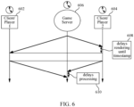
- FIG. 6 illustrates an example of enforcing network latency fairness in an environment in which clients (e.g., UEs) and network entities are externally synchronized, in accordance with certain aspects of the present disclosure.
- the clients and network entities may be synchronized, for example, based on an external clock, such as a clock associated with a cellular telecommunications system (e.g., a clock maintained by a core network entity or a base station) or a clock associated with a satellite positioning system (e.g., NAVSTAR GPS, GLONASS, GALILEO, etc.).
- a cellular telecommunications system e.g., a clock maintained by a core network entity or a base station
- a satellite positioning system e.g., NAVSTAR GPS, GLONASS, GALILEO, etc.
- a client device can periodically measure end-to-end downlink latency.
- End-to-end downlink latency may be, for example, the difference between a timestamp included in a downlink packet identifying when the downlink packet was transmitted by the game server and a time at which the downlink packet was received by the client device (UE).
- the measured end-to-end downlink latency may be reported back to the game server, and the game server can adjust a downlink media playout timestamp based on the maximum end-to-end downlink latency reported by the clients connected with the game server.
- the game server can transmit downlink packets to the client devices connected with the game server with a timestamp indicating when the content included in the downlink packets is to be played out on each of the client devices.
- the timestamp may be set such that client devices that receive the downlink packet before the identified play out time delays rendering the content included in the downlink packets until the play out time.
- each client device may timestamp uplink packets with a timestamp identifying a time at which the uplink packets were transmitted to the game server.
- the game server can estimate a maximum uplink delay across all client devices based the timestamp included in uplink packets and a time at which the game server receives the uplink packets. Based on the maximum uplink delay, the game server can wait to process uplink packets before processing the data in the uplink packets, and the uplink packets may be ordered based on the transmission timestamps included in each uplink packet.
- client device 1 602 may be located a greater distance away from the game server 606 than client device 2 604, and thus, may have a larger latency for downlink and uplink packets.
- Client device 1 602 may receive downlink packets from the game server 606 later than client device 2 604, and the game server 606 may receive uplink packets transmitted from client device 1 602 later than uplink packets transmitted from client device 2 604 at the same time.
- client device 1 602 may play out a downlink packet on receipt, and client device 2 604 may delay playing out the downlink packet according to a delay 608, which may be based on a time difference between arrival of a packet at client device 1 602 and the packet at client device 2 604 (and communicated to client device 2 604 from game server 606 or some other network entity).
- a delay 608 may be based on a time difference between arrival of a packet at client device 1 602 and the packet at client device 2 604 (and communicated to client device 2 604 from game server 606 or some other network entity).
- the game server 606 can delay processing an uplink packet from client device 2 604 based on a measured uplink latency 610, and the game server 606 can process an uplink packet from client device 1 602 upon receipt.
- delaying processing of received packets at a client device delaying processing of uplink packets from a client device at game server 606 may prevent a user of client device 2 604 from being unfairly advantaged over a user of client device 1 602 by, for example, triggering various events in the multi-user gaming environment before similar events can be triggered by receipt and processing of packets from client device 1 602.
- low latency may be orthogonal to fairness.
- Existing network procedures may set a packet delay budget (PDB) that is needed to support game play.
- PDB packet delay budget
- IP internet protocol
- IP layer protocols may not be able to guarantee accuracy, as uplink and downlink delays may be asymmetrical and may vary over time.
- various techniques for clock synchronization may exist.
- UEs may be able to use information in system information blocks (SIBs) to synchronize with a base station; however, new features may be needed to synchronize a game server with the base station, as the game server may not be connected to the base station via a radio interface.
- SIBs system information blocks
- Using external sources such as a clock associated with a satellite positioning system, may allow for high accuracy; however, support may not be consistent as devices located indoors or in poor coverage may not be able to lock onto a satellite positioning system signal and thus may not be able to synchronize a device clock with a satellite positioning system clock.
- FIGs. 7A and 7B illustrate examples of enforcing network latency fairness in environments in which clients and network entities are unsynchronized, according to aspects described herein.
- the game server 706 and/or client devices 702 and 704 may periodically measure round-trip time (RTT) for communications between each other.
- RTT round-trip time
- An end-to-end delay may be estimated based on an assumption that uplink and downlink delays are symmetric (e.g., that both uplink and downlink delays are 1 ⁇ 2 * RTT).
- Such an assumption may be warranted, for example, based on assumptions that transmissions on an uplink channel will experience similar radio characteristics to transmissions on a downlink channel, as one channel may be considered the converse of the other channel and transmissions may be performed according to similar radio propagation and interference characteristics.
- FIG. 7A illustrates an example in which a game server 706 enforces network latency fairness in an environment in which clients devices 702 and 704 and network entities are unsynchronized.
- the game server 706 may impose a handicap on client devices that have an estimated end-to-end delay that is less than a maximum end-to-end delay.
- the handicap may be implemented as a transmission delay 710 for communications from game server 706 to a client device (e.g., client device 704 illustrated in FIG. 7A ) and as a processing delay for communications from a client device to the game server 706.
- Transmission of downlink packets may be delayed until a time such that recipients of such downlink packets may receive and process these packets at substantially the same time.
- Processing of uplink packets may be delayed at the game server until such a time that uplink packets transmitted by different client devices at the same transmission time are processed at the game server at the same time.
- FIG. 7B illustrates an example in which a client device (e.g., client devices 702 and 704 illustrated in FIG. 7B ) enforces network latency fairness in an environment in which client devices and network entities (e.g., a game server 706) are unsynchronized.
- a handicap may be communicated from the game server 706 to each client device 702, 704 served by the game server 706.
- the client devices 702, 704 may delay processing of received downlink packets and may delay transmission of uplink packets to the game server based on the handicap 720 communicated to the client devices 702, 704 by the game server 706.
- the handicap 720 may be symmetric and applicable to both uplink and downlink transmissions from a client device.
- end-to-end delay estimates may be inaccurate. For example, errors caused by uplink/downlink asymmetry and variances in delay caused by the radio conditions, a scheduler, and/or network congestion may result in an inaccurate measurement of end-to-end delay.
- an asymmetrical uplink/downlink delay where the downlink delay is less than the uplink delay may result in a user seeing a situation sooner but being delayed in performing actions within the gaming environment.
- various techniques may be used to assist a game server in enforcing latency fairness in a multi-user gaming environment.
- the network may assist in enforcing latency fairness in a multi-user gaming environment.
- a game server may be connected with a WAN via an IP network connection to a user plane function (UPF) or other core radio access network (RAN) entity.
- Latency between the game server and a client device (UE) may be a combination of IP network delays between the game server and UPF, N3 delays between the UPF and a base station, and RAN delays between the base station and the client device.
- a similar delay may be applied to communications between the central game server and the one or more UPFs.
- a similar delay may be applied to communications between the central game server and the one or more UPFs.
- Such a case may exist, for example, when a central game server is located near UPFs in a network or at a location in which delays between the central game server and each UPF is substantially similar.
- FIG. 8 illustrates an example in which network latency fairness is enforced using edge servers or UPFs synchronized with a central server, according to certain aspects described herein.
- different amounts of delay may exist between the central game server 804, UPF1 802a, UPF2 802b, and UPF3 802c.
- UPF2 802b which may be located at a largest distance from the central game server 804, may have the largest delay d2.
- UPF3 802c located at a shortest distance from the central game server 804, may have the shortest delay d3.
- the edge servers (which may be collocated with respective UPFs) or UPFs 802 may be synchronized with the central game server 804 via one or more timing protocols (e.g., network time protocol, synchronization with a satellite positioning system clock, etc.).
- timing protocols e.g., network time protocol, synchronization with a satellite positioning system clock, etc.
- the techniques discussed above with respect to FIGs. 6 , 7A , and/or 7B may be used to measure delay between an edge server or UPF 802 and the central game server 804 to compensate for IP network delays between the game server and a radio access network.
- a radio access network (RAN) packet delay budget may be used to compensate for server-to-UPF delays.
- a game server may set a packet delay budget for each UPF to account for IP network delays.
- the central server may measure delays to each UPF based on a round trip time (e.g., 1 ⁇ 2 * RTT) to each UPF or based on clock synchronization with the UPFs to make measurements.
- the game server may then compensate for delay variations between the UPFs by setting PDB limits for each UE under a UPF such that UPFs with a shortest delay have a largest delay budget and UPFs with longer delays have smaller delay budgets.
- a RAN may be used to manage delays and enforce latency among UEs or other client devices participating in a multi-user gaming environment.
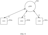
- FIG. 9 illustrates an example in which a RAN scheduler may be used to enforce network latency fairness, according to certain aspects described herein.
- grant times t1 for UE1 702a, t2 for UE2 902b, and t3 for UE3 902c may be configured such that downlink packets arrive at the UEs 902 at the same time and uplink packets are ready for transmission from the UEs 902 at the same time.
- a RAN scheduler at gNodeB 904 may, for example, set a RAN packet delay budget (PDB) to reduce variance among UEs connected with the base station.
- PDB RAN packet delay budget
- the PDB may be, for example, set based on a maximum packet delay with a set confidence level, which may reduce variance in when packets are received or transmitted by the UEs at some expense in respect of network capacity.
- the RAN scheduler at gNodeB 904 may deliver traffic based on a specified packet delay target, and no sooner than the packet delay target.
- a QoS identifier (5QI) may be defined with a scheduler algorithm that may impact capacity.
- the QoS requirements defined by a RAN scheduler may impact an ability to meet the packet delay target with retransmissions.
- Enforcing network latency fairness may also increase in complexity as the number of users or a data rate increases, as increases in the number of users or a data rate in a network may reduce a packet delay budget or an ability to enforce network latency fairness while balancing performance considerations at various client devices in a multi-user gaming platform.
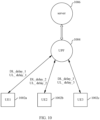
- FIG. 10 illustrates an example of enforcing network latency fairness in which a user plane function (UPF) 1004 may be used to improve fairness across UEs 1002 in a multi-user gaming environment.
- the UPF 1004 may use, for example, QoS assist procedures (e.g., QoS procedures defined for ultra-reliable low latency communications (URLLC) systems) to measure an average uplink and downlink delay between the UPF 1004 and each UE 1002.
- QoS assist procedures e.g., QoS procedures defined for ultra-reliable low latency communications (URLLC) systems
- the UPF 1004 may handicap or otherwise delay forwarding downlink packets to UEs 1002 with shorter average downlink delays such that downlink packets are received by UE1 1002a, UE2 1002b, and UE3 1002c at the same time or substantially the same time.
- the UPF 1004 may handicap or otherwise delay forwarding of uplink packets from UEs 1002 with shorter uplink delays to a game server 1006 such that uplink packets transmitted by the UEs 1002 at the same time are delivered to the game server at the same time or substantially the same time.
- fairness may be limited by how closely the average uplink/downlink delay estimates match actual packet transport delays.
- the UPF 1004 illustrated in FIG. 10 may not compensate for variations in uplink and downlink latencies.
- the game server 1006 may compensate for uplink and downlink delays based on UPF reports.
- the UPF 1004 may, for example, use QoS assist procedures to measure average uplink and downlink delays and transmit a report to the game server 1006 with uplink and downlink delay measurements for each UE 1002.
- the server 1006 and UPF 1004 may measure these delays based, for example, on a measured round trip time or clock synchronization between the UPF 1004 and game server 1006 via a precision time protocol (PTP). Delays may be measured, and the game server 1006 may compensate for server-to-UPF and uplink/downlink delays in forwarding downlink packets or processing uplink packets.
- PTP precision time protocol
- FIG. 11 illustrates an example network architecture in which timestamping can be used to enforce network latency fairness.
- a game server 1102 may communicate with a corresponding application 1112 executing on a UE 1110 by transmitting downlink packets through a time sensitive network (TSN) working domain 1104 to a UPF 1106.
- TSN time sensitive network
- the UPF 1106 generally forwards packets to a base station 1108, and the base station 1108 then forwards those packets to UE 1110 for delivery to the application 1112.
- Uplink communications may be transmitted from the application 1112 executing on the UE 1110 to a base station 1108, which may forward the packet to a UPF 1106.
- the UPF 1106 may then then forward the packet to a game server 1102 via the TSN working domain 1104.
- RAN clock information which may be sourced from clocks at the UPF 1106 and UE 1110 synchronized via various precision time protocols (e.g., gPTP), may be used to compensate for delays within the RAN.
- Clock synchronization may be enabled between the TSN working domain 1104 and a UE 1110 and application 1112 executing thereon. Clock synchronization may also be used in the techniques described above.
- uplink and downlink packets may be timestamped.
- the UPF may timestamp downlink media packets with playout times based on an expected playout time and a maximum downlink delay identified across the UEs participating in the multi-user gaming environment.
- the UE may delay delivery of a downlink packet to the application executing on the UE for just-in-time delivery and playout in the application based on the timestamp in the downlink media packets.
- the UE may timestamp packets based on the common clock with a transmission time from the UE.
- the UPF may use a maximum uplink delay across the UEs participating in the multi-user gaming environment to determine when to forward packets to the game server, and uplink packets may be ordered based on the timestamps included in these packets.
- a UPF can use a guaranteed bit rate and determine a maximum packet delay budget (PDB) for all UEs admitted to the multi-user gaming environment.
- PDB packet delay budget
- a policy may be defined to admit UEs with a same PDB value.
- QoS Assisted URLLC delay measurement procedures may be used to measure average uplink/downlink delays for each UE, as discussed above.
- a margin may be added to the maximum average uplink/downlink delay to compensate for variances above the average delay.
- synchronized clocks at the UE and UPF may be used to directly measure a maximum delay.
- the uplink delay may be measured directly by the UPF for each uplink packet as the difference between the packet arrival time at the UPF and a packet timestamp included in the uplink packet.
- the downlink delay may be measured by transmitting packets with a non-playout-time timestamp (e.g., a transmission time from the UPF), and the UE may measure a downlink delay based on a difference between the time at which the UE received the downlink packet and the non-playout-time timestamp. The measured downlink delay may be reported back to the UPF.
- a non-playout-time timestamp e.g., a transmission time from the UPF
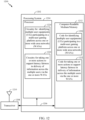
- FIG. 12 illustrates a communications device 1200 that may include various components (e.g., corresponding to means-plus-function components) configured to perform operations for the techniques disclosed herein, such as the operations illustrated in FIG. 4 .
- the communications device 1200 includes a processing system 1202 coupled to a transceiver 1208.
- the transceiver 1208 is configured to transmit and receive signals for the communications device 1200 via an antenna 1210, such as the various signals as described herein.
- the processing system 1202 may be configured to perform processing functions for the communications device 1200, including processing signals received and/or to be transmitted by the communications device 1200.
- the processing system 1202 includes a processor 1204 coupled to a computer-readable medium/memory 1212 via a bus 1206.
- the computer-readable medium/memory 1212 is configured to store instructions (e.g., computer-executable code) that when executed by the processor 1204, cause the processor 1204 to perform the operations illustrated in FIG. 4 , or other operations for enforcing network latency fairness in multi-user gaming platforms.
- computer-readable medium/memory 1212 stores code 1220 for identifying multiple user equipments (UEs) participating in a multi-user gaming platform across one or more wide area networks (WANs); and code 1222 for taking one or more actions to support latency fairness in delivery of information across the multiple users via the one or more WANs.
- UEs user equipments
- WANs wide area networks
- the processor 1204 has circuitry configured to implement the code stored in the computer-readable medium/memory 1212.
- the processor 1204 includes circuitry 1230 for identifying multiple user equipments (UEs) participating in a multi-user gaming platform across one or more wide area networks (WANs); and circuitry 1232 for taking one or more actions to support latency fairness in delivery of information across the multiple users via the one or more WANs.
- UEs user equipments
- WANs wide area networks
- FIG. 13 illustrates a communications device 1300 that may include various components (e.g., corresponding to means-plus-function components) configured to perform operations for the techniques disclosed herein, such as the operations illustrated in FIG. 5 .
- the communications device 1300 includes a processing system 1302 coupled to a transceiver 1308.
- the transceiver 1308 is configured to transmit and receive signals for the communications device 1300 via an antenna 1310, such as the various signals as described herein.
- the processing system 1302 may be configured to perform processing functions for the communications device 1300, including processing signals received and/or to be transmitted by the communications device 1300.
- the processing system 1302 includes a processor 1304 coupled to a computer-readable medium/memory 1312 via a bus 1306.
- the computer-readable medium/memory 1312 is configured to store instructions (e.g., computer-executable code) that when executed by the processor 1304, cause the processor 1304 to perform the operations illustrated in FIG. 5 , or other operations for enforcing network latency fairness in multi-user gaming platforms.
- computer-readable medium/memory 1312 stores code 1320 for determining parameters of communications with a network entity; and code 1322 for taking one or more actions to support latency fairness with other UEs in delivery of information based on the determined parameters.
- the processor 1304 has circuitry configured to implement the code stored in the computer-readable medium/memory 1312.
- the processor 1304 includes circuitry 1330 for determining parameters of communications with a network entity; and circuitry 1332 for taking one or more actions to support latency fairness with other UEs in delivery of information based on the determined parameters.
- NR for example, 5G NR
- LTE Long Term Evolution
- LTE-A LTE-Advanced
- CDMA code division multiple access
- TDMA time division multiple access
- FDMA frequency division multiple access
- OFDMA orthogonal frequency division multiple access
- SC-FDMA single-carrier frequency division multiple access
- TD-SCDMA time division synchronous code division multiple access
- a CDMA network may implement a radio technology such as Universal Terrestrial Radio Access (UTRA), cdma2000, etc.
- UTRA includes Wideband CDMA (WCDMA) and other variants of CDMA.
- cdma2000 covers IS-2000, IS-95 and IS-856 standards.
- a TDMA network may implement a radio technology such as Global System for Mobile Communications (GSM).
- GSM Global System for Mobile Communications
- An OFDMA network may implement a radio technology such as NR (e.g. 5G RA), Evolved UTRA (E-UTRA), Ultra Mobile Broadband (UMB), IEEE 802.11 (Wi-Fi), IEEE 802.16 (WiMAX), IEEE 802.20, Flash-OFDMA, etc.
- E-UTRA Evolved UTRA
- UMB Ultra Mobile Broadband
- Wi-Fi Wi-Fi
- WiMAX IEEE 802.16
- IEEE 802.20 Flash-OFDMA
- UTRA and E-UTRA are part of Universal Mobile Telecommunication System (UMTS).
- LTE and LTE-A are releases of UMTS that use E-UTRA.
- UTRA, E-UTRA, UMTS, LTE, LTE-A and GSM are described in documents from an organization named "3rd Generation Partnership Project” (3GPP).
- cdma2000 and UMB are described in documents from an organization named “3rd Generation Partnership Project 2" (3GPP2).
- NR is an emerging wireless communications technology under development.
- the term “cell” can refer to a coverage area of a Node B (NB) or a NB subsystem serving this coverage area, depending on the context in which the term is used.
- NB Node B
- BS next generation NodeB
- AP access point
- DU distributed unit
- TRP transmission reception point
- a BS may provide communication coverage for a macro cell, a pico cell, a femto cell, or other types of cells.
- a macro cell may cover a relatively large geographic area (for example, several kilometers in radius) and may allow unrestricted access by UEs with service subscription.
- a pico cell may cover a relatively small geographic area and may allow unrestricted access by UEs with service subscription.
- a femto cell may cover a relatively small geographic area (for example, a home) and may allow restricted access by UEs having an association with the femto cell (for example, UEs in a Closed Subscriber Group (CSG), UEs for users in the home, etc.).
- a BS for a macro cell may be referred to as a macro BS.
- a BS for a pico cell may be referred to as a pico BS.
- a BS for a femto cell may be referred to as a femto BS or a home BS.
- a UE may also be referred to as a mobile station, a terminal, an access terminal, a subscriber unit, a station, a Customer Premises Equipment (CPE), a cellular phone, a smart phone, a personal digital assistant (PDA), a wireless modem, a wireless communication device, a handheld device, a laptop computer, a cordless phone, a wireless local loop (WLL) station, a tablet computer, a camera, a gaming device, a netbook, a smartbook, an ultrabook, an appliance, a medical device or medical equipment, a biometric sensor/device, a wearable device such as a smart watch, smart clothing, smart glasses, a smart wrist band, smart jewelry (for example, a smart ring, a smart bracelet, etc.), an entertainment device (for example, a music device, a video device, a satellite radio, etc.), a vehicular component or sensor, a smart meter/sensor, industrial manufacturing equipment, a global positioning system device, or any other suitable device that is
- Some UEs may be considered machine-type communication (MTC) devices or evolved MTC (eMTC) devices.
- MTC and eMTC UEs include, for example, robots, drones, remote devices, sensors, meters, monitors, location tags, etc., that may communicate with a BS, another device (for example, remote device), or some other entity.
- a wireless node may provide, for example, connectivity for or to a network (for example, a wide area network such as Internet or a cellular network) via a wired or wireless communication link.
- Some UEs may be considered Internet-of-Things (IoT) devices, which may be narrowband IoT (NB-IoT) devices.
- IoT Internet-of-Things
- NB-IoT narrowband IoT
- Some wireless networks utilize orthogonal frequency division multiplexing (OFDM) on the downlink and single-carrier frequency division multiplexing (SC-FDM) on the uplink.
- OFDM and SC-FDM partition the system bandwidth into multiple (K) orthogonal subcarriers, which are also commonly referred to as tones, bins, etc.
- K orthogonal subcarriers
- Each subcarrier may be modulated with data.
- modulation symbols are sent in the frequency domain with OFDM and in the time domain with SC-FDM.
- the spacing between adjacent subcarriers may be fixed, and the total number of subcarriers (K) may be dependent on the system bandwidth.
- the spacing of the subcarriers may be 15 kHz and the minimum resource allocation (called a "resource block” (RB)) may be 12 subcarriers (or 180 kHz). Consequently, the nominal Fast Fourier Transfer (FFT) size may be equal to 128, 256, 512, 1024 or 2048 for system bandwidth of 1.25, 2.5, 5, 10, or 20 megahertz (MHz), respectively.
- the system bandwidth may also be partitioned into subbands. For example, a subband may cover 1.08 MHz (for example, 6 RBs), and there may be 1, 2, 4, 8, or 16 subbands for system bandwidth of 1.25, 2.5, 5, 10 or 20 MHz, respectively.
- the basic transmission time interval (TTI) or packet duration is the 1 ms subframe.
- NR may utilize OFDM with a CP on the uplink and downlink and include support for half-duplex operation using TDD.
- a subframe is still 1 ms, but the basic TTI is referred to as a slot.
- a subframe contains a variable number of slots (for example, 1, 2, 4, 8, 16, ... slots) depending on the subcarrier spacing.
- the NR RB is 12 consecutive frequency subcarriers.
- NR may support a base subcarrier spacing of 15 KHz and other subcarrier spacing may be defined with respect to the base subcarrier spacing, for example, 30 kHz, 60 kHz, 120 kHz, 240 kHz, etc.
- the symbol and slot lengths scale with the subcarrier spacing.
- the CP length also depends on the subcarrier spacing.
- Beamforming may be supported and beam direction may be dynamically configured.
- MIMO transmissions with precoding may also be supported.
- MIMO configurations in the DL may support up to 8 transmit antennas with multi-layer DL transmissions up to 8 streams and up to 2 streams per UE.
- multi-layer transmissions with up to 2 streams per UE may be supported.
- Aggregation of multiple cells may be supported with up to 8 serving cells.
- a scheduling entity (for example, a BS) allocates resources for communication among some or all devices and equipment within its service area or cell.
- the scheduling entity may be responsible for scheduling, assigning, reconfiguring, and releasing resources for one or more subordinate entities. That is, for scheduled communication, subordinate entities utilize resources allocated by the scheduling entity.
- Base stations are not the only entities that may function as a scheduling entity.
- a UE may function as a scheduling entity and may schedule resources for one or more subordinate entities (for example, one or more other UEs), and the other UEs may utilize the resources scheduled by the UE for wireless communication.
- a UE may function as a scheduling entity in a peer-to-peer (P2P) network, or in a mesh network.
- P2P peer-to-peer
- UEs may communicate directly with one another in addition to communicating with a scheduling entity.
- determining may encompass one or more of a wide variety of actions. For example, “determining” may include calculating, computing, processing, deriving, investigating, looking up (for example, looking up in a table, a database or another data structure), assuming and the like. Also, “determining” may include receiving (for example, receiving information), accessing (for example, accessing data in a memory) and the like. Also, “determining” may include resolving, selecting, choosing, establishing and the like.
- a or b may include a only, b only, or a combination of a and b.
- a phrase referring to "at least one of” or “one or more of” a list of items refers to any combination of those items, including single members.
- "at least one of: a, b, or c” is intended to cover the possibilities of: a only, b only, c only, a combination of a and b, a combination of a and c, a combination of b and c, and a combination of a and b and c.
Landscapes
- Engineering & Computer Science (AREA)
- Computer Networks & Wireless Communication (AREA)
- Signal Processing (AREA)
- Multimedia (AREA)
- Physics & Mathematics (AREA)
- General Physics & Mathematics (AREA)
- Business, Economics & Management (AREA)
- Environmental & Geological Engineering (AREA)
- General Business, Economics & Management (AREA)
- Accounting & Taxation (AREA)
- Computer Security & Cryptography (AREA)
- Strategic Management (AREA)
- Theoretical Computer Science (AREA)
- General Health & Medical Sciences (AREA)
- Cardiology (AREA)
- Health & Medical Sciences (AREA)
- Mobile Radio Communication Systems (AREA)
- Display Devices Of Pinball Game Machines (AREA)
Claims (15)
- Verfahren für Kommunikationen durch ein Netzwerksystem, das Folgendes beinhaltet:Identifizieren (402) mehrerer Benutzergeräte, UEs, die an einer Mehrbenutzer-Spieleplattform über ein oder mehrere Weitverkehrsnetze, WANs, teilnehmen; undDurchführen (404) einer oder mehrerer Aktionen zum Unterstützen von Latenzfairness beim Liefern von Informationen über die mehreren Benutzer über die ein oder mehreren WANs;wobei das Netzwerksystem eine Benutzerebenenfunktion, UPF, umfasst; undwobei die UPF und die UEs mit einem gemeinsamen Takt synchronisiert sind und die ein oder mehreren Aktionen mindestens eines beinhalten von:Einfügen, auf der Basis des gemeinsamen Takts und einer maximalen Downlink-Verzögerung für alle UEs, eines Zeitstempels in Downlink-Medienpakete mit Playout-Zeiten; oderNutzen einer maximalen Uplink-Verzögerung für alle UEs, gemessen auf der Basis des gemeinsamen Takts, um eine Wartezeit für die Weiterleitung von Uplink-Paketen zu bestimmen.
- Verfahren nach Anspruch 1, wobei das Netzwerksystem ferner einen Spielserver umfasst, und wobei die ein oder mehreren Aktionen Folgendes beinhalten:Empfangen von Berichten von den mehreren UEs, die Downlink-Latenz zwischen dem Spielserver und den mehreren UEs angeben; undJustieren, auf der Basis der Berichte, eines Downlink-Medien-Playout-Zeitstempels, der von den mehreren UEs verwendet wird, um zu bestimmen, wann Downlink-Medien abgespielt werden sollen.
- Verfahren nach Anspruch 1, wobei das Netzwerksystem ferner einen Spielserver umfasst, und wobei die ein oder mehreren Aktionen Folgendes beinhalten:
Bestimmen eines Handicaps für eines oder mehrere der mehreren UEs auf der Basis von geschätzten Link-Verzögerungen zwischen dem Spielserver und den mehreren UEs. - Verfahren nach Anspruch 3, wobei die ein oder mehreren Aktionen ferner mindestens eines beinhalten von:Verzögern der Downlink-Paketübertragung auf der Basis des Handicaps; oderVerzögern der Uplink-Paketverarbeitung auf der Basis des Handicaps; oderÜbermitteln des Handicaps an mindestens eines der UEs.
- Verfahren nach Anspruch 1, wobei die ein oder mehreren Aktionen Folgendes beinhalten:Synchronisieren mit einem oder mehreren Edge-Servern oder Benutzerebenenfunktionen, UPFs zum Kompensieren von Verzögerungsvariationen in den ein oder mehreren WANs; oderVerfahren nach Anspruch 1, wobei die ein oder mehreren Aktionen Folgendes beinhalten:Empfangen von Berichten von einer oder mehreren Benutzerebenenfunktionen, UPFs, die eine Uplink-Verzögerung und/oder eine Downlink-Verzögerung zwischen UEs und den UPFs anzeigen; undKompensieren von Verzögerungsvariationen in den ein oder mehreren WANs auf der Basis der Berichte;oderVerfahren nach Anspruch 1, wobei die ein oder mehreren Aktionen Folgendes beinhalten:Schätzen von Verzögerungen zwischen dem Netzwerksystem und einer oder mehreren Benutzerebenenfunktionen, UPFs; undKompensieren von Verzögerungsvariationen in den ein oder mehreren WANs durch Festlegen von PDB-(Paket Delay Budget)-Grenzen für das UE auf der Basis der geschätzten Verzögerungen; oderVerfahren nach Anspruch 1, wobei das Netzwerksystem ferner eine Basisstation umfasst und die ein oder mehreren Aktionen mindestens eines beinhalten von:Festlegen einer PDB-(Paket Delay Budget)-Grenze zum Reduzieren von Variationen zwischen den UEs; oderPlanen von Verkehrslieferung bei einem bestimmten Paketverzögerungsziel.
- Verfahren nach Anspruch 1, wobei die ein oder mehreren Aktionen Folgendes beinhalten:Messen von durchschnittlichen Downlink-Verzögerungen zwischen der UPF und einem oder mehreren der UEs; undHandicappen und/oder Verzögern der Weiterleitung von Downlink-Paketen von einem Server zu UEs auf der Basis der Messung; oderVerfahren nach Anspruch 1, wobei die ein oder mehreren Aktionen Folgendes beinhalten:Messen von durchschnittlichen Uplink-Verzögerungen zwischen einem oder mehreren der UEs und der UPF; undHandicappen und/oder Verzögern der Weiterleitung von Uplink-Paketen zu einem Server auf der Basis der Messung.
- Verfahren nach Anspruch 1, wobei:die maximale Uplink-Verzögerung für alle UEs eine maximale durchschnittliche Uplink-Verzögerung für alle UEs plus einer Uplink-Varianzmarge umfasst und die maximale Downlink-Verzögerung für alle UEs eine maximale durchschnittliche Downlink-Verzögerung für alle UEs plus einer Downlink-Varianzmarge umfasst; oderdie maximale Uplink-Verzögerung für alle UEs auf der Basis einer Differenz zwischen einer Paketankunftszeit an der UPF und einem Paketzeitstempel in Uplink-Paketen von den UEs bestimmt wird und die maximale Downlink-Verzögerung für alle UEs auf der Basis von Berichten von den UEs über eine Differenz zwischen einer Paketankunftszeit an den UEs und einem Paketzeitstempel in zu den UEs übertragenen Downlink-Paketen bestimmt wird.
- Verfahren zur Kommunikation durch ein an einer Mehrbenutzer-Spieleplattform teilnehmendes Benutzergerät, UE, das Folgendes beinhaltet:Bestimmen (502) von Parametern der Kommunikation mit einem Netzwerksystem; undAusführen (504) einer oder mehrerer Aktionen zur Unterstützung von Latenzfairness mit anderen UEs bei der Lieferung von Informationen auf der Basis der bestimmten Parameter;wobei das Netzwerksystem eine Benutzerebenenfunktion, UPF, umfasst; undwobei das UE und die UPF mit einem gemeinsamen Takt synchronisiert sind und die ein oder mehreren Aktionen mindestens eines beinhalten von:Abspielen empfangener Downlink-Medienpakete auf der Basis eines Playout-Zeitstempels auf der Basis des gemeinsamen Takts und einer maximalen Downlink-Verzögerung für alle an der Mehrbenutzer-Spieleplattform teilnehmenden UEs; oderEinfügen eines Zeitstempels auf der Basis des gemeinsamen Takts in Uplink-Pakete zur Verwendung durch die UPF bei der Bestimmung von Uplink-Paketverzögerungen und/oder Weiterleitung der Uplink-Pakete an einen Spielserver.
- Verfahren nach Anspruch 8, wobei das Netzwerksystem ferner einen Spielserver umfasst, und wobei die ein oder mehreren Aktionen Folgendes beinhalten:Übertragen, zum Spielserver, von Berichten, die Downlink-Latenz zwischen dem Spielserver und dem UE angeben; oderVerfahren nach Anspruch 8, wobei das Netzwerksystem ferner einen Spielserver umfasst, und wobei die ein oder mehreren Aktionen Folgendes beinhalten:
Übertragen von Uplink-Daten mit Zeitstempeln zu dem Spielserver zur Verwendung beim Schätzen von Uplink-Verzögerungen zwischen dem UE und dem Spielserver und/oder Verzögern der Verarbeitung von Spielereingaben am Spielserver. - Verfahren nach Anspruch 8,wobei das Netzwerksystem ferner einen Spielserver umfasst, und wobei die Parameter der Kommunikation mit dem Netzwerksystem eine maximale Uplink-Verzögerung für an der Mehrbenutzer-Spieleplattform teilnehmende UEs umfassen und die ein oder mehreren Aktionen das Verzögern der Übertragung von Uplink-Daten zum Spielserver auf der Basis der maximalen Uplink-Verzögerung umfassen; oderwobei die Parameter der Kommunikation mit dem Netzwerksystem ein von dem Netzwerksystem empfangenes Handicap für das UE umfassen und die ein oder mehreren Aktionen mindestens eines beinhalten von:Verzögern der Uplink-Paketübertragung zu dem Spielserver auf der Basis des Handicaps; oderVerzögern der Lieferung von Downlink-Paketen an eine auf dem UE ausgeführte Anwendung auf der Basis des Handicaps.
- Verfahren nach Anspruch 8, wobei das Netzwerksystem ferner eine Basisstation umfasst und die ein oder mehreren Aktionen Folgendes beinhalten:Kommunizieren mit dem Netzwerksystem auf der Basis einer PDB-(Paket Delay Budget)-Grenze, festgelegt zum Reduzieren von Variationen zwischen an der Mehrbenutzer-Spieleplattform teilnehmenden UEs; oderKommunizieren mit dem Netzwerksystem auf der Basis eines spezifizierten Paketverzögerungsziels.
- Verfahren nach Anspruch 8, wobei die ein oder mehreren Aktionen ferner mindestens eines beinhalten von:Kommunizieren mit dem Netzwerksystem auf der Basis eines PDB (Paket Delay Budget) für das UE und eines maximalen PDB für alle an der Mehrbenutzer-Spieleplattform teilnehmenden UEs; oderKommunizieren mit dem Netzwerksystem auf der Basis eines gleichen PDB-Werts für alle an der Mehrbenutzer-Spieleplattform teilnehmenden UEs.
- Verfahren nach Anspruch 8,wobei die maximale Uplink-Verzögerung für alle an der Mehrbenutzer-Spieleplattform teilnehmenden UEs eine maximale durchschnittliche Uplink-Verzögerung für alle UEs plus einer Uplink-Varianzmarge umfasst und die maximale Downlink-Verzögerung für alle an der Mehrbenutzer-Spieleplattform teilnehmenden UEs eine maximale durchschnittliche Downlink-Verzögerung für alle UEs plus einer Downlink-Varianzmarge umfasst; oderwobei die maximale Uplink-Verzögerung für alle UEs auf der Basis einer Differenz zwischen einer Paketankunftszeit an der UPF und einem in Uplink-Paketen von den UEs enthaltenen Paketzeitstempel bestimmt wird und die maximale Downlink-Verzögerung für alle UEs auf der Basis von Berichten von den UEs über eine Differenz zwischen einer Paketankunftszeit an den UEs und einem in zu den UEs übertragenen Downlink-Paketen enthaltenen Paketzeitstempel bestimmt wird.
- Vorrichtung, die Folgendes umfasst:einen Speicher mit darauf gespeicherten ausführbaren Befehlen; undeinen Prozessor, konfiguriert zum Ausführen der ausführbaren Befehle, um die Vorrichtung zum Durchführen des Verfahrens nach einem der Ansprüche 1-7 zu veranlassen.
- Vorrichtung, die Folgendes umfasst:einen Speicher mit darauf gespeicherten ausführbaren Befehlen; undeinen Prozessor, konfiguriert zum Ausführen der ausführbaren Befehle, um die Vorrichtung zum Durchführen des Verfahrens nach einem der Ansprüche 8-13 zu veranlassen.
Applications Claiming Priority (3)
| Application Number | Priority Date | Filing Date | Title |
|---|---|---|---|
| US202063066144P | 2020-08-14 | 2020-08-14 | |
| US17/400,493 US11611510B2 (en) | 2020-08-14 | 2021-08-12 | Network latency fairness in multi-user gaming platforms |
| PCT/US2021/045890 WO2022036184A1 (en) | 2020-08-14 | 2021-08-13 | Network latency fairness in multi-user gaming platforms |
Publications (3)
| Publication Number | Publication Date |
|---|---|
| EP4197166A1 EP4197166A1 (de) | 2023-06-21 |
| EP4197166C0 EP4197166C0 (de) | 2025-04-30 |
| EP4197166B1 true EP4197166B1 (de) | 2025-04-30 |
Family
ID=80223423
Family Applications (1)
| Application Number | Title | Priority Date | Filing Date |
|---|---|---|---|
| EP21769839.8A Active EP4197166B1 (de) | 2020-08-14 | 2021-08-13 | Fairness bei der netzlatenz in multi-user-gaming-plattformen |
Country Status (6)
| Country | Link |
|---|---|
| US (1) | US11611510B2 (de) |
| EP (1) | EP4197166B1 (de) |
| KR (1) | KR102852535B1 (de) |
| CN (1) | CN116075343A (de) |
| BR (1) | BR112023002002A2 (de) |
| WO (1) | WO2022036184A1 (de) |
Families Citing this family (3)
| Publication number | Priority date | Publication date | Assignee | Title |
|---|---|---|---|---|
| WO2022255932A1 (en) * | 2021-06-04 | 2022-12-08 | Telefonaktiebolaget Lm Ericsson (Publ) | Improving time synchronization accuracy in a wireless network |
| US11627063B1 (en) * | 2021-12-02 | 2023-04-11 | Verizon Patent And Licensing Inc. | Systems and methods for measuring unidirectional latency of applications over asymmetric links |
| WO2024047262A1 (es) * | 2022-08-30 | 2024-03-07 | Take Profit Gaming, S.L. | Método de interacción online eliminando el efecto de la latencia de red |
Family Cites Families (10)
| Publication number | Priority date | Publication date | Assignee | Title |
|---|---|---|---|---|
| US7416488B2 (en) | 2001-07-18 | 2008-08-26 | Duplicate (2007) Inc. | System and method for playing a game of skill |
| US7133927B2 (en) * | 2002-04-29 | 2006-11-07 | Lucent Technologies Inc. | Method and apparatus for supporting real-time multi-user distributed applications |
| US7584248B2 (en) * | 2004-02-27 | 2009-09-01 | Alcatel-Lucent Usa Inc. | Apparatus and method for fair message exchanges in distributed multi-player games |
| US20060135258A1 (en) | 2004-12-17 | 2006-06-22 | Nokia Corporation | System, network entity, client and method for facilitating fairness in a multiplayer game |
| US7680038B1 (en) * | 2005-04-25 | 2010-03-16 | Electronic Arts, Inc. | Dynamic bandwidth detection and response for online games |
| WO2007119236A2 (en) * | 2006-04-13 | 2007-10-25 | Yosef Mizrachi | Method and apparatus for providing gaming services and for handling video content |
| US9308455B1 (en) * | 2006-10-25 | 2016-04-12 | Marvell International Ltd. | System and method for gaming in an ad-hoc network |
| US10898802B2 (en) * | 2018-05-31 | 2021-01-26 | Sony Interactive Entertainment LLC | Bifurcation of shared controls and passing controls in a video game |
| US10924525B2 (en) * | 2018-10-01 | 2021-02-16 | Microsoft Technology Licensing, Llc | Inducing higher input latency in multiplayer programs |
| US20210118085A1 (en) * | 2019-10-22 | 2021-04-22 | Synergy Blue, Llc | Methods, devices and systems for multi-player virtual hybrid wager-based and non-wager-based competitions |
-
2021
- 2021-08-12 US US17/400,493 patent/US11611510B2/en active Active
- 2021-08-13 KR KR1020237004766A patent/KR102852535B1/ko active Active
- 2021-08-13 EP EP21769839.8A patent/EP4197166B1/de active Active
- 2021-08-13 BR BR112023002002A patent/BR112023002002A2/pt unknown
- 2021-08-13 CN CN202180056181.8A patent/CN116075343A/zh active Pending
- 2021-08-13 WO PCT/US2021/045890 patent/WO2022036184A1/en not_active Ceased
Also Published As
| Publication number | Publication date |
|---|---|
| CN116075343A (zh) | 2023-05-05 |
| US11611510B2 (en) | 2023-03-21 |
| US20220052954A1 (en) | 2022-02-17 |
| BR112023002002A2 (pt) | 2023-03-07 |
| KR20230049093A (ko) | 2023-04-12 |
| EP4197166C0 (de) | 2025-04-30 |
| WO2022036184A1 (en) | 2022-02-17 |
| KR102852535B1 (ko) | 2025-08-29 |
| EP4197166A1 (de) | 2023-06-21 |
Similar Documents
| Publication | Publication Date | Title |
|---|---|---|
| CN112514296B (zh) | 协调发射的反馈模式指示 | |
| CN112219358B (zh) | 用于共享频谱中毫米波系统的波束完善参考信号(brrs)设计 | |
| CN115085892B (zh) | 非周期性跟踪参考信号 | |
| KR102776732B1 (ko) | 부대역 및 간섭 측정을 사용한 무선 링크 모니터링 | |
| CN113940026B (zh) | 侧行链路操作 | |
| US20200107286A1 (en) | Systems and methods for network procedures for on-demand random access channel (rach) | |
| CN112514291B (zh) | 用于远程干扰管理的参考信号监视机制 | |
| CN115735387B (zh) | 基于云的服务的端到端时间同步 | |
| CN118019048A (zh) | 用于控制资源集和下行链路带宽部分的空间准共址指示 | |
| EP4197166B1 (de) | Fairness bei der netzlatenz in multi-user-gaming-plattformen | |
| US11711794B2 (en) | Applying a common beam for multiple signals to a default physical downlink shared channel (PDSCH) beam | |
| US10856319B2 (en) | Link dependent scheduling request format for URLLC | |
| CN112243573A (zh) | 用于跨载波调度的非周期性信道状态信息计算 | |
| US11617170B2 (en) | Uplink beam failure report and beam reset for multiple component carriers | |
| CN110771062A (zh) | 通过基于ue波束的打标进行qcl指示 | |
| CN113056885A (zh) | 具有针对相同csi参考信号(csi-rs)资源的不同准共处一地(qcl)配置的信道状态信息(csi)测量 | |
| WO2022005350A1 (en) | A fronthaul network unit and method therein for synchronization over a fronthaul network | |
| US11743836B2 (en) | Reduction of path loss (PL) reference signal (RS) application time | |
| US20230217358A1 (en) | Staggering transmission to wireless clients based on wireless network information | |
| CN115606278B (zh) | 确定用于多输入多输出(mimo)的上行链路默认波束 | |
| CN115104362B (zh) | 在触发的传输时间之前应用的更新的波束 | |
| CN116746101A (zh) | 用于确定基于下行链路控制信息(dci)的更新的应用时间的规则 | |
| CN115104278B (zh) | 分量载波之间的ue探测过程 | |
| CN115669121B (zh) | 物理层交叉链路干扰测量和报告 |
Legal Events
| Date | Code | Title | Description |
|---|---|---|---|
| STAA | Information on the status of an ep patent application or granted ep patent |
Free format text: STATUS: UNKNOWN |
|
| STAA | Information on the status of an ep patent application or granted ep patent |
Free format text: STATUS: THE INTERNATIONAL PUBLICATION HAS BEEN MADE |
|
| PUAI | Public reference made under article 153(3) epc to a published international application that has entered the european phase |
Free format text: ORIGINAL CODE: 0009012 |
|
| STAA | Information on the status of an ep patent application or granted ep patent |
Free format text: STATUS: REQUEST FOR EXAMINATION WAS MADE |
|
| 17P | Request for examination filed |
Effective date: 20230207 |
|
| AK | Designated contracting states |
Kind code of ref document: A1 Designated state(s): AL AT BE BG CH CY CZ DE DK EE ES FI FR GB GR HR HU IE IS IT LI LT LU LV MC MK MT NL NO PL PT RO RS SE SI SK SM TR |
|
| DAV | Request for validation of the european patent (deleted) | ||
| DAX | Request for extension of the european patent (deleted) | ||
| REG | Reference to a national code |
Ref legal event code: R079 Free format text: PREVIOUS MAIN CLASS: H04L0009400000 Ref country code: DE Ref legal event code: R079 Ref document number: 602021030069 Country of ref document: DE Free format text: PREVIOUS MAIN CLASS: H04L0009400000 Ipc: H04L0067131000 |
|
| RIC1 | Information provided on ipc code assigned before grant |
Ipc: H04L 43/106 20220101ALN20240614BHEP Ipc: H04L 43/0852 20220101ALN20240614BHEP Ipc: H04L 43/067 20220101ALN20240614BHEP Ipc: H04L 41/5067 20220101ALN20240614BHEP Ipc: H04W 28/02 20090101ALI20240614BHEP Ipc: H04L 47/56 20220101ALI20240614BHEP Ipc: H04L 47/28 20220101ALI20240614BHEP Ipc: G06Q 20/32 20120101ALI20240614BHEP Ipc: A63F 13/44 20140101ALI20240614BHEP Ipc: H04L 69/28 20220101ALI20240614BHEP Ipc: G07F 17/32 20060101ALI20240614BHEP Ipc: A63F 13/358 20140101ALI20240614BHEP Ipc: H04L 67/131 20220101AFI20240614BHEP |
|
| GRAP | Despatch of communication of intention to grant a patent |
Free format text: ORIGINAL CODE: EPIDOSNIGR1 |
|
| STAA | Information on the status of an ep patent application or granted ep patent |
Free format text: STATUS: GRANT OF PATENT IS INTENDED |
|
| RIC1 | Information provided on ipc code assigned before grant |
Ipc: H04L 43/106 20220101ALN20240710BHEP Ipc: H04L 43/0852 20220101ALN20240710BHEP Ipc: H04L 43/067 20220101ALN20240710BHEP Ipc: H04L 41/5067 20220101ALN20240710BHEP Ipc: H04W 28/02 20090101ALI20240710BHEP Ipc: H04L 47/56 20220101ALI20240710BHEP Ipc: H04L 47/28 20220101ALI20240710BHEP Ipc: G06Q 20/32 20120101ALI20240710BHEP Ipc: A63F 13/44 20140101ALI20240710BHEP Ipc: H04L 69/28 20220101ALI20240710BHEP Ipc: G07F 17/32 20060101ALI20240710BHEP Ipc: A63F 13/358 20140101ALI20240710BHEP Ipc: H04L 67/131 20220101AFI20240710BHEP |
|
| INTG | Intention to grant announced |
Effective date: 20240808 |
|
| GRAJ | Information related to disapproval of communication of intention to grant by the applicant or resumption of examination proceedings by the epo deleted |
Free format text: ORIGINAL CODE: EPIDOSDIGR1 |
|
| STAA | Information on the status of an ep patent application or granted ep patent |
Free format text: STATUS: REQUEST FOR EXAMINATION WAS MADE |
|
| GRAP | Despatch of communication of intention to grant a patent |
Free format text: ORIGINAL CODE: EPIDOSNIGR1 |
|
| STAA | Information on the status of an ep patent application or granted ep patent |
Free format text: STATUS: GRANT OF PATENT IS INTENDED |
|
| INTC | Intention to grant announced (deleted) | ||
| RIC1 | Information provided on ipc code assigned before grant |
Ipc: H04L 43/106 20220101ALN20241128BHEP Ipc: H04L 43/0852 20220101ALN20241128BHEP Ipc: H04L 43/067 20220101ALN20241128BHEP Ipc: H04L 41/5067 20220101ALN20241128BHEP Ipc: H04W 28/02 20090101ALI20241128BHEP Ipc: H04L 47/56 20220101ALI20241128BHEP Ipc: H04L 47/28 20220101ALI20241128BHEP Ipc: G06Q 20/32 20120101ALI20241128BHEP Ipc: A63F 13/44 20140101ALI20241128BHEP Ipc: H04L 69/28 20220101ALI20241128BHEP Ipc: G07F 17/32 20060101ALI20241128BHEP Ipc: A63F 13/358 20140101ALI20241128BHEP Ipc: H04L 67/131 20220101AFI20241128BHEP |
|
| INTG | Intention to grant announced |
Effective date: 20241206 |
|
| GRAS | Grant fee paid |
Free format text: ORIGINAL CODE: EPIDOSNIGR3 |
|
| GRAA | (expected) grant |
Free format text: ORIGINAL CODE: 0009210 |
|
| STAA | Information on the status of an ep patent application or granted ep patent |
Free format text: STATUS: THE PATENT HAS BEEN GRANTED |
|
| AK | Designated contracting states |
Kind code of ref document: B1 Designated state(s): AL AT BE BG CH CY CZ DE DK EE ES FI FR GB GR HR HU IE IS IT LI LT LU LV MC MK MT NL NO PL PT RO RS SE SI SK SM TR |
|
| REG | Reference to a national code |
Ref country code: CH Ref legal event code: EP Ref country code: GB Ref legal event code: FG4D |
|
| REG | Reference to a national code |
Ref country code: IE Ref legal event code: FG4D |
|
| REG | Reference to a national code |
Ref country code: DE Ref legal event code: R096 Ref document number: 602021030069 Country of ref document: DE |
|
| U01 | Request for unitary effect filed |
Effective date: 20250519 |
|
| U07 | Unitary effect registered |
Designated state(s): AT BE BG DE DK EE FI FR IT LT LU LV MT NL PT RO SE SI Effective date: 20250526 |
|
| U20 | Renewal fee for the european patent with unitary effect paid |
Year of fee payment: 5 Effective date: 20250710 |
|
| PG25 | Lapsed in a contracting state [announced via postgrant information from national office to epo] |
Ref country code: ES Free format text: LAPSE BECAUSE OF FAILURE TO SUBMIT A TRANSLATION OF THE DESCRIPTION OR TO PAY THE FEE WITHIN THE PRESCRIBED TIME-LIMIT Effective date: 20250430 |
|
| PG25 | Lapsed in a contracting state [announced via postgrant information from national office to epo] |
Ref country code: GR Free format text: LAPSE BECAUSE OF FAILURE TO SUBMIT A TRANSLATION OF THE DESCRIPTION OR TO PAY THE FEE WITHIN THE PRESCRIBED TIME-LIMIT Effective date: 20250731 Ref country code: NO Free format text: LAPSE BECAUSE OF FAILURE TO SUBMIT A TRANSLATION OF THE DESCRIPTION OR TO PAY THE FEE WITHIN THE PRESCRIBED TIME-LIMIT Effective date: 20250730 |
|
| PG25 | Lapsed in a contracting state [announced via postgrant information from national office to epo] |
Ref country code: PL Free format text: LAPSE BECAUSE OF FAILURE TO SUBMIT A TRANSLATION OF THE DESCRIPTION OR TO PAY THE FEE WITHIN THE PRESCRIBED TIME-LIMIT Effective date: 20250430 |
|
| PGFP | Annual fee paid to national office [announced via postgrant information from national office to epo] |
Ref country code: GB Payment date: 20250710 Year of fee payment: 5 |
|
| PG25 | Lapsed in a contracting state [announced via postgrant information from national office to epo] |
Ref country code: HR Free format text: LAPSE BECAUSE OF FAILURE TO SUBMIT A TRANSLATION OF THE DESCRIPTION OR TO PAY THE FEE WITHIN THE PRESCRIBED TIME-LIMIT Effective date: 20250430 |
|
| PG25 | Lapsed in a contracting state [announced via postgrant information from national office to epo] |
Ref country code: RS Free format text: LAPSE BECAUSE OF FAILURE TO SUBMIT A TRANSLATION OF THE DESCRIPTION OR TO PAY THE FEE WITHIN THE PRESCRIBED TIME-LIMIT Effective date: 20250731 |
|
| PGFP | Annual fee paid to national office [announced via postgrant information from national office to epo] |
Ref country code: IE Payment date: 20250709 Year of fee payment: 5 |
|
| PG25 | Lapsed in a contracting state [announced via postgrant information from national office to epo] |
Ref country code: IS Free format text: LAPSE BECAUSE OF FAILURE TO SUBMIT A TRANSLATION OF THE DESCRIPTION OR TO PAY THE FEE WITHIN THE PRESCRIBED TIME-LIMIT Effective date: 20250830 |
|
| PG25 | Lapsed in a contracting state [announced via postgrant information from national office to epo] |
Ref country code: SM Free format text: LAPSE BECAUSE OF FAILURE TO SUBMIT A TRANSLATION OF THE DESCRIPTION OR TO PAY THE FEE WITHIN THE PRESCRIBED TIME-LIMIT Effective date: 20250430 |
|
| PG25 | Lapsed in a contracting state [announced via postgrant information from national office to epo] |
Ref country code: CZ Free format text: LAPSE BECAUSE OF FAILURE TO SUBMIT A TRANSLATION OF THE DESCRIPTION OR TO PAY THE FEE WITHIN THE PRESCRIBED TIME-LIMIT Effective date: 20250430 |
|
| PG25 | Lapsed in a contracting state [announced via postgrant information from national office to epo] |
Ref country code: SK Free format text: LAPSE BECAUSE OF FAILURE TO SUBMIT A TRANSLATION OF THE DESCRIPTION OR TO PAY THE FEE WITHIN THE PRESCRIBED TIME-LIMIT Effective date: 20250430 |
|
| PLBE | No opposition filed within time limit |
Free format text: ORIGINAL CODE: 0009261 |
|
| STAA | Information on the status of an ep patent application or granted ep patent |
Free format text: STATUS: NO OPPOSITION FILED WITHIN TIME LIMIT |
|
| REG | Reference to a national code |
Ref country code: CH Ref legal event code: L10 Free format text: ST27 STATUS EVENT CODE: U-0-0-L10-L00 (AS PROVIDED BY THE NATIONAL OFFICE) Effective date: 20260311 |
|
| REG | Reference to a national code |
Ref country code: CH Ref legal event code: H13 Free format text: ST27 STATUS EVENT CODE: U-0-0-H10-H13 (AS PROVIDED BY THE NATIONAL OFFICE) Effective date: 20260324 |
|
| PG25 | Lapsed in a contracting state [announced via postgrant information from national office to epo] |
Ref country code: MC Free format text: LAPSE BECAUSE OF FAILURE TO SUBMIT A TRANSLATION OF THE DESCRIPTION OR TO PAY THE FEE WITHIN THE PRESCRIBED TIME-LIMIT Effective date: 20250430 |
|
| 26N | No opposition filed |
Effective date: 20260202 |
|
| PG25 | Lapsed in a contracting state [announced via postgrant information from national office to epo] |
Ref country code: CH Free format text: LAPSE BECAUSE OF NON-PAYMENT OF DUE FEES Effective date: 20250831 |