EP4196366B1 - System and method for vehicle-side control of a multi-pile charging session - Google Patents
System and method for vehicle-side control of a multi-pile charging session Download PDFInfo
- Publication number
- EP4196366B1 EP4196366B1 EP21802845.4A EP21802845A EP4196366B1 EP 4196366 B1 EP4196366 B1 EP 4196366B1 EP 21802845 A EP21802845 A EP 21802845A EP 4196366 B1 EP4196366 B1 EP 4196366B1
- Authority
- EP
- European Patent Office
- Prior art keywords
- charging
- bcu
- secc
- pile
- vehicle
- Prior art date
- Legal status (The legal status is an assumption and is not a legal conclusion. Google has not performed a legal analysis and makes no representation as to the accuracy of the status listed.)
- Active
Links
Images


Classifications
-
- B—PERFORMING OPERATIONS; TRANSPORTING
- B60—VEHICLES IN GENERAL
- B60L—PROPULSION OF ELECTRICALLY-PROPELLED VEHICLES; SUPPLYING ELECTRIC POWER FOR AUXILIARY EQUIPMENT OF ELECTRICALLY-PROPELLED VEHICLES; ELECTRODYNAMIC BRAKE SYSTEMS FOR VEHICLES IN GENERAL; MAGNETIC SUSPENSION OR LEVITATION FOR VEHICLES; MONITORING OPERATING VARIABLES OF ELECTRICALLY-PROPELLED VEHICLES; ELECTRIC SAFETY DEVICES FOR ELECTRICALLY-PROPELLED VEHICLES
- B60L53/00—Methods of charging batteries, specially adapted for electric vehicles; Charging stations or on-board charging equipment therefor; Exchange of energy storage elements in electric vehicles
- B60L53/60—Monitoring or controlling charging stations
- B60L53/67—Controlling two or more charging stations
-
- B—PERFORMING OPERATIONS; TRANSPORTING
- B60—VEHICLES IN GENERAL
- B60L—PROPULSION OF ELECTRICALLY-PROPELLED VEHICLES; SUPPLYING ELECTRIC POWER FOR AUXILIARY EQUIPMENT OF ELECTRICALLY-PROPELLED VEHICLES; ELECTRODYNAMIC BRAKE SYSTEMS FOR VEHICLES IN GENERAL; MAGNETIC SUSPENSION OR LEVITATION FOR VEHICLES; MONITORING OPERATING VARIABLES OF ELECTRICALLY-PROPELLED VEHICLES; ELECTRIC SAFETY DEVICES FOR ELECTRICALLY-PROPELLED VEHICLES
- B60L53/00—Methods of charging batteries, specially adapted for electric vehicles; Charging stations or on-board charging equipment therefor; Exchange of energy storage elements in electric vehicles
- B60L53/60—Monitoring or controlling charging stations
- B60L53/66—Data transfer between charging stations and vehicles
-
- B—PERFORMING OPERATIONS; TRANSPORTING
- B60—VEHICLES IN GENERAL
- B60L—PROPULSION OF ELECTRICALLY-PROPELLED VEHICLES; SUPPLYING ELECTRIC POWER FOR AUXILIARY EQUIPMENT OF ELECTRICALLY-PROPELLED VEHICLES; ELECTRODYNAMIC BRAKE SYSTEMS FOR VEHICLES IN GENERAL; MAGNETIC SUSPENSION OR LEVITATION FOR VEHICLES; MONITORING OPERATING VARIABLES OF ELECTRICALLY-PROPELLED VEHICLES; ELECTRIC SAFETY DEVICES FOR ELECTRICALLY-PROPELLED VEHICLES
- B60L53/00—Methods of charging batteries, specially adapted for electric vehicles; Charging stations or on-board charging equipment therefor; Exchange of energy storage elements in electric vehicles
- B60L53/10—Methods of charging batteries, specially adapted for electric vehicles; Charging stations or on-board charging equipment therefor; Exchange of energy storage elements in electric vehicles characterised by the energy transfer between the charging station and the vehicle
- B60L53/14—Conductive energy transfer
- B60L53/16—Connectors, e.g. plugs or sockets, specially adapted for charging electric vehicles
-
- B—PERFORMING OPERATIONS; TRANSPORTING
- B60—VEHICLES IN GENERAL
- B60L—PROPULSION OF ELECTRICALLY-PROPELLED VEHICLES; SUPPLYING ELECTRIC POWER FOR AUXILIARY EQUIPMENT OF ELECTRICALLY-PROPELLED VEHICLES; ELECTRODYNAMIC BRAKE SYSTEMS FOR VEHICLES IN GENERAL; MAGNETIC SUSPENSION OR LEVITATION FOR VEHICLES; MONITORING OPERATING VARIABLES OF ELECTRICALLY-PROPELLED VEHICLES; ELECTRIC SAFETY DEVICES FOR ELECTRICALLY-PROPELLED VEHICLES
- B60L53/00—Methods of charging batteries, specially adapted for electric vehicles; Charging stations or on-board charging equipment therefor; Exchange of energy storage elements in electric vehicles
- B60L53/10—Methods of charging batteries, specially adapted for electric vehicles; Charging stations or on-board charging equipment therefor; Exchange of energy storage elements in electric vehicles characterised by the energy transfer between the charging station and the vehicle
- B60L53/14—Conductive energy transfer
- B60L53/18—Cables specially adapted for charging electric vehicles
-
- B—PERFORMING OPERATIONS; TRANSPORTING
- B60—VEHICLES IN GENERAL
- B60L—PROPULSION OF ELECTRICALLY-PROPELLED VEHICLES; SUPPLYING ELECTRIC POWER FOR AUXILIARY EQUIPMENT OF ELECTRICALLY-PROPELLED VEHICLES; ELECTRODYNAMIC BRAKE SYSTEMS FOR VEHICLES IN GENERAL; MAGNETIC SUSPENSION OR LEVITATION FOR VEHICLES; MONITORING OPERATING VARIABLES OF ELECTRICALLY-PROPELLED VEHICLES; ELECTRIC SAFETY DEVICES FOR ELECTRICALLY-PROPELLED VEHICLES
- B60L53/00—Methods of charging batteries, specially adapted for electric vehicles; Charging stations or on-board charging equipment therefor; Exchange of energy storage elements in electric vehicles
- B60L53/30—Constructional details of charging stations
- B60L53/305—Communication interfaces
-
- B—PERFORMING OPERATIONS; TRANSPORTING
- B60—VEHICLES IN GENERAL
- B60L—PROPULSION OF ELECTRICALLY-PROPELLED VEHICLES; SUPPLYING ELECTRIC POWER FOR AUXILIARY EQUIPMENT OF ELECTRICALLY-PROPELLED VEHICLES; ELECTRODYNAMIC BRAKE SYSTEMS FOR VEHICLES IN GENERAL; MAGNETIC SUSPENSION OR LEVITATION FOR VEHICLES; MONITORING OPERATING VARIABLES OF ELECTRICALLY-PROPELLED VEHICLES; ELECTRIC SAFETY DEVICES FOR ELECTRICALLY-PROPELLED VEHICLES
- B60L53/00—Methods of charging batteries, specially adapted for electric vehicles; Charging stations or on-board charging equipment therefor; Exchange of energy storage elements in electric vehicles
- B60L53/60—Monitoring or controlling charging stations
- B60L53/68—Off-site monitoring or control, e.g. remote control
-
- B—PERFORMING OPERATIONS; TRANSPORTING
- B60—VEHICLES IN GENERAL
- B60L—PROPULSION OF ELECTRICALLY-PROPELLED VEHICLES; SUPPLYING ELECTRIC POWER FOR AUXILIARY EQUIPMENT OF ELECTRICALLY-PROPELLED VEHICLES; ELECTRODYNAMIC BRAKE SYSTEMS FOR VEHICLES IN GENERAL; MAGNETIC SUSPENSION OR LEVITATION FOR VEHICLES; MONITORING OPERATING VARIABLES OF ELECTRICALLY-PROPELLED VEHICLES; ELECTRIC SAFETY DEVICES FOR ELECTRICALLY-PROPELLED VEHICLES
- B60L2200/00—Type of vehicles
- B60L2200/32—Waterborne vessels
-
- B—PERFORMING OPERATIONS; TRANSPORTING
- B60—VEHICLES IN GENERAL
- B60L—PROPULSION OF ELECTRICALLY-PROPELLED VEHICLES; SUPPLYING ELECTRIC POWER FOR AUXILIARY EQUIPMENT OF ELECTRICALLY-PROPELLED VEHICLES; ELECTRODYNAMIC BRAKE SYSTEMS FOR VEHICLES IN GENERAL; MAGNETIC SUSPENSION OR LEVITATION FOR VEHICLES; MONITORING OPERATING VARIABLES OF ELECTRICALLY-PROPELLED VEHICLES; ELECTRIC SAFETY DEVICES FOR ELECTRICALLY-PROPELLED VEHICLES
- B60L2250/00—Driver interactions
-
- B—PERFORMING OPERATIONS; TRANSPORTING
- B60—VEHICLES IN GENERAL
- B60Y—INDEXING SCHEME RELATING TO ASPECTS CROSS-CUTTING VEHICLE TECHNOLOGY
- B60Y2200/00—Type of vehicle
- B60Y2200/90—Vehicles comprising electric prime movers
- B60Y2200/91—Electric vehicles
-
- Y—GENERAL TAGGING OF NEW TECHNOLOGICAL DEVELOPMENTS; GENERAL TAGGING OF CROSS-SECTIONAL TECHNOLOGIES SPANNING OVER SEVERAL SECTIONS OF THE IPC; TECHNICAL SUBJECTS COVERED BY FORMER USPC CROSS-REFERENCE ART COLLECTIONS [XRACs] AND DIGESTS
- Y02—TECHNOLOGIES OR APPLICATIONS FOR MITIGATION OR ADAPTATION AGAINST CLIMATE CHANGE
- Y02T—CLIMATE CHANGE MITIGATION TECHNOLOGIES RELATED TO TRANSPORTATION
- Y02T10/00—Road transport of goods or passengers
- Y02T10/60—Other road transportation technologies with climate change mitigation effect
- Y02T10/70—Energy storage systems for electromobility, e.g. batteries
-
- Y—GENERAL TAGGING OF NEW TECHNOLOGICAL DEVELOPMENTS; GENERAL TAGGING OF CROSS-SECTIONAL TECHNOLOGIES SPANNING OVER SEVERAL SECTIONS OF THE IPC; TECHNICAL SUBJECTS COVERED BY FORMER USPC CROSS-REFERENCE ART COLLECTIONS [XRACs] AND DIGESTS
- Y02—TECHNOLOGIES OR APPLICATIONS FOR MITIGATION OR ADAPTATION AGAINST CLIMATE CHANGE
- Y02T—CLIMATE CHANGE MITIGATION TECHNOLOGIES RELATED TO TRANSPORTATION
- Y02T10/00—Road transport of goods or passengers
- Y02T10/60—Other road transportation technologies with climate change mitigation effect
- Y02T10/7072—Electromobility specific charging systems or methods for batteries, ultracapacitors, supercapacitors or double-layer capacitors
-
- Y—GENERAL TAGGING OF NEW TECHNOLOGICAL DEVELOPMENTS; GENERAL TAGGING OF CROSS-SECTIONAL TECHNOLOGIES SPANNING OVER SEVERAL SECTIONS OF THE IPC; TECHNICAL SUBJECTS COVERED BY FORMER USPC CROSS-REFERENCE ART COLLECTIONS [XRACs] AND DIGESTS
- Y02—TECHNOLOGIES OR APPLICATIONS FOR MITIGATION OR ADAPTATION AGAINST CLIMATE CHANGE
- Y02T—CLIMATE CHANGE MITIGATION TECHNOLOGIES RELATED TO TRANSPORTATION
- Y02T90/00—Enabling technologies or technologies with a potential or indirect contribution to GHG emissions mitigation
- Y02T90/10—Technologies relating to charging of electric vehicles
- Y02T90/12—Electric charging stations
-
- Y—GENERAL TAGGING OF NEW TECHNOLOGICAL DEVELOPMENTS; GENERAL TAGGING OF CROSS-SECTIONAL TECHNOLOGIES SPANNING OVER SEVERAL SECTIONS OF THE IPC; TECHNICAL SUBJECTS COVERED BY FORMER USPC CROSS-REFERENCE ART COLLECTIONS [XRACs] AND DIGESTS
- Y02—TECHNOLOGIES OR APPLICATIONS FOR MITIGATION OR ADAPTATION AGAINST CLIMATE CHANGE
- Y02T—CLIMATE CHANGE MITIGATION TECHNOLOGIES RELATED TO TRANSPORTATION
- Y02T90/00—Enabling technologies or technologies with a potential or indirect contribution to GHG emissions mitigation
- Y02T90/10—Technologies relating to charging of electric vehicles
- Y02T90/14—Plug-in electric vehicles
-
- Y—GENERAL TAGGING OF NEW TECHNOLOGICAL DEVELOPMENTS; GENERAL TAGGING OF CROSS-SECTIONAL TECHNOLOGIES SPANNING OVER SEVERAL SECTIONS OF THE IPC; TECHNICAL SUBJECTS COVERED BY FORMER USPC CROSS-REFERENCE ART COLLECTIONS [XRACs] AND DIGESTS
- Y02—TECHNOLOGIES OR APPLICATIONS FOR MITIGATION OR ADAPTATION AGAINST CLIMATE CHANGE
- Y02T—CLIMATE CHANGE MITIGATION TECHNOLOGIES RELATED TO TRANSPORTATION
- Y02T90/00—Enabling technologies or technologies with a potential or indirect contribution to GHG emissions mitigation
- Y02T90/10—Technologies relating to charging of electric vehicles
- Y02T90/16—Information or communication technologies improving the operation of electric vehicles
- Y02T90/167—Systems integrating technologies related to power network operation and communication or information technologies for supporting the interoperability of electric or hybrid vehicles, i.e. smartgrids as interface for battery charging of electric vehicles [EV] or hybrid vehicles [HEV]
Definitions
- the present disclosure relates to electric vehicle charging. More particularly, the present disclosure relates to vehicle-side control of a multi-pile charging session comprising independent charging sessions.
- Charging piles of a charging substation are used for the controlled transfer of electrical power to electrical vehicles during charging sessions.
- Charging piles can be used in a commercial setting, wherein customers use the charging pile to charge their electric vehicle at a charging facility hosting one or more charging substations.
- the charging piles are often in data communication with a server through a network.
- the server typically includes a database including vehicle records for the customers and meter records documenting each charging session performed by the charging piles.
- a vehicle identifier for the electric vehicle is typically sent to the server.
- the final power delivery totals are stored in the meter records of the server's database.
- the server is thereafter accessed by the vendor to conduct customer billing procedures for charging sessions.
- Charging ports on the electric vehicles are connected to charging connectors of the charging pile, often through an umbilical line spanning the distance therebetween.
- Industry standards typically dictate: (i) dimensions of the charging connectors and charging ports; (ii) voltage ranges for the charging piles; and (iii) current ranges for the charging piles.
- Widely implemented industry standards for the charging piles and initiation of separate charging sessions are included within ISO 15118/DIN 70121 and the national standard GB/T27930-2015. Charging piles following these standards can be used for many types of electric vehicles (typically passenger cars, buses, ferries, trolleys, and trains).
- An example publication for multi-pile charging sessions is Chinese Patent Application No. CN109760545A, dated 17 May 2019 and entitled "Charging Method and Charging Device”.
- This publication describes the use of multiple charging piles of a charging substation to simultaneously charge an electric vehicle in a multi-pile charging session.
- One of the charging piles of the charging substation is designated the master charging pile.
- the master charging pile of the charging substation controls both its own charging session and the charging sessions of the other charging piles (designated "slave" charging piles) of the same charging substation.
- coordination of the separate charging sessions for each of the charging piles of the charging substation is performed by the master charging pile of the charging substation.
- CN109760545A presents a method to coordinate the multi-pile charging session, it requires both a hardware modification (e.g., dedicated communication lines between each of the charging piles of the charging substation) and a software modification to the standardized communication protocols (e.g., to override the need for specific protocol messaging between the electric vehicle and the slave charging pile through the slave charging port).
- a hardware modification e.g., dedicated communication lines between each of the charging piles of the charging substation
- a software modification to the standardized communication protocols e.g., to override the need for specific protocol messaging between the electric vehicle and the slave charging pile through the slave charging port.
- the operation of other charging piles may also be affected due to communication error signals. For instance, faults detected during initiation of the charging piles of the charging substation could halt the entire multi-pile charging session.
- a large charging facility may support multiple charging substations operated by different vendors. These multiple charging substations may be unconnected to each other.
- the master/slave protocols of the prior art assumes that the master charging pile and the slave charging pile are operated by the same vendor (and hence only require a single authorization from the vendor routed through the master charging pile). Thus, an electric vehicle would be unable to perform a multi-pile charging session using charging piles selected from the charging substations of multiple vendors located at the same charging facility.
- US2020/122593A1 Noh et, al entitled “Vehicle and Method for Controlling the same” discloses a vehicle and a method for controlling the vehicle.
- the vehicle may include multiple charging ports electrically coupled to a first connector and a second connector.
- Each of the first and second connectors is configured to receive power from one or more charger; and a controller is configured to receive a charging start command and, upon receiving the charging start command, to control operation of the vehicle to be sequentially paired with the first connector and the second connector when the first connector and the second connector are electrically coupled to the multiple charging ports.
- WO2011/062037A1 Anegawa et al entitled “Charging System, Charger, Electric Movable Body, and Method for Charging Battery for Electric Movable Body” discloses a technique that is capable of more reliably starting and completing a charging control sequence even when a communication error occurs due to noise and that is also capable of reliably opening a relay except for during charging.
- driving power supply lines used for supplying driving power from a control-system power supply to a relay disposed between the charging line and an in-vehicle battery.
- US2013/041531A1 Lafrance , entitled “Vehicle Controllers and Methods for use in charging an electrically powered vehicle” discloses methods and vehicle controllers for use in charging an electrically powered vehicle.
- One example vehicle controller includes a memory device configured to store a user-profile and a processor electrically coupled to the memory device. The processor is programmed to detect a vehicle charging station, retrieve the user profile from the memory device, and communicate the user profile to the vehicle charging station. The user profile includes billing information.
- WO2018/190796A1 discloses a battery fleet charging system for charging one or more batteries simultaneously at independently controlled charge rates.
- the disclosed charging system can intelligently distribute an available charging power among multiple battery chargers, either symmetrically or asymmetrically. as specified by a central controller to regulate the power used by each battery charger.
- US2018/0304759A1 discloses an intelligent vehicle charging system for charging a fleet of autonomous vehicles throughout a network of charging stations dispersed throughout a geographic area.
- the intelligent vehicle charging system includes a remote control system that is in operative communication with each of the autonomous vehicles in the fleet and each of the charging stations in the network.
- the remote control system will identify an available charging station, guide the autonomous vehicle to the charging station, verify that the autonomous vehicle has arrived at the charging station, initiate the power charging process, account and bill appropriate fees for the charging process, and log all associated activity.
- the remote control system is also capable of remotely and instantaneously terminating the power charging process to dynamically return a vehicle back to service.
- CN 108248434A entitled “Electric vehicle charge control method and device” discloses a charging control method and device for an electric vehicle.
- the electric vehicle includes two charging interfaces.
- the two charging interfaces are used to connect to two charging guns of a charging pile.
- the two charging interfaces are respectively connected to a battery management system through two CAN lines.
- the method includes detecting whether the two charging guns of the charging pile are physically connected to the two charging interfaces. If so, the method includes establishing a communication connection between the battery management system and the charging pile through the two CAN lines: sending the charging demand to the charging pile through the two CAN lines so that the charging pile can simultaneously charge the electric vehicle through the two charging guns according to the charging demand.
- the charging requirements include at least charging voltage requirements and charging current requirements.
- the two charging guns of the charging pile can be controlled to simultaneously charge the same electric vehicle through the two CAN lines, which solves the problem of slow charging.
- US2011/241824A1 entitled "IN-vehicle Mount Type Battery Charging System, Managing Server, Managing Server Control Method and Computer-readable Medium Storing Program for Managing Server” discloses an in-vehicle mount type battery charging system including a charging station having a charger for charging an in-vehicle mount battery of an electric vehicle, and a managing server connected to the charger.
- the managing server receives registration for enabling use of the charger from a user, authenticates the user when the user uses the charger and allows the user to use the charger when the user is authenticated as a registered member.
- the managing server receives temporary registration for temporarily enabling use of the charger from a user as a nonmember, authenticates the user when the user uses the charger and temporarily allows the user to use the charger when the user is authenticated as a registered temporary member.
- US2020/125052, Jeong entitled “Power Supply Apparatus and System, and Method for using the same” discloses a power supply apparatus for supplying power to an external electric device.
- the power supply apparatus includes a power outlet unit to which a power plug of the external electric device is coupled, to supply electricity to the external electric device; a power control unit controlling power supply from the power outlet unit to the external electric device; and a user interface unit connected to the power control unit to receive a power activation code from a user, wherein the power control unit supplies power from the power outlet unit to the external electric device during a usage period, corresponding to the power activation code.
- the invention is a system or method for vehicle-side control of a multi-pile charging session, the system comprising: (a) a plurality of charging piles, each charging pile including a supply equipment communication controller (SECC); and (b) a vehicle electrical system for an electric vehicle with a master battery control unit (MBCU) in data communication with a plurality of battery control units (BCU).
- SECC supply equipment communication controller
- MBCU master battery control unit
- BCU battery control units
- the MBCU is configured to coordinate two or more independent charging sessions through the BCUs during each multi-pile charging session.
- Each independent charging session is managed with an independent protocol message exchange through a BCU-to-SECC communication pathway.
- a first embodiment of the invention is a system for vehicle-side control of a multi-pile charging session, the system comprising: (a) a plurality of charging piles; and (b) a vehicle electrical system for an electric vehicle.
- Each charging pile comprises: (i) a power line electrically connected to a power connector at a first end and to a charging connector at a second end; and (ii) a supply equipment communication controller (SECC).
- SECC supply equipment communication controller
- the power line is connectable to a utility line.
- the power line includes a relay switch positioned between the power connector and the charging connector.
- a charging pile power line communication module (CP-PLC) is positioned adjacent the power line between the relay switch and the charging connector.
- the SECC is in data communication with the relay switch and the CP-PLC.
- the vehicle electrical system includes: (i) a battery including a plurality of battery management units (BMUs) and a plurality of battery cells; (ii) a busbar relay in electrical connection to the battery cells via at least one busbar battery trunk; (iii) a plurality of charging ports; (iv) a plurality of busbar input trunks; and (v) a master battery control unit (MBCU).
- BMUs battery management units
- MBCU master battery control unit
- Each charging port is configured for electrical connection to the charging connector of one of the charging piles.
- the charging port is directly electrically connected to the charging connector or the charging port is indirectly electrically connected to the charging connector through an umbilical line.
- Each busbar input trunk is electrically connected to one of the charging ports at a first junction and to the busbar relay at a second junction.
- Each busbar input trunk is in data communication with an electric vehicle power line communication module (EV-PLC) positioned adjacent the busbar input trunk between the charging port associated with the busbar input trunk and the busbar relay.
- the MBCU is in data communication with a plurality of battery control units (BCU), the BMUs of the battery, the busbar relay, and a user interface device.
- Each BCU is paired in data communication with one of the EV-PLCs to establish a BCU-to-SECC communication pathway for the BCU upon a connective pairing of the charging port associated with the BCU and one of the charging connectors.
- the BCU-to-SECC communication pathway for each BCU passes from the BCU to the EV-PLC associated with the BCU, to the busbar input trunk associated with the EV-PLC, to the connectively paired charging port associated with the busbar input trunk, to the connectively paired charging connector associated with the connectively paired charging port, to the power line associated with the connectively paired charging connector, to the CP-PLC associated with the power line, and to the SECC associated with the CP-PLC.
- the MBCU is configured to: (a) coordinate two or more independent charging sessions during each multi-pile charging session to charge the battery cells simultaneously through two or more charging ports according to a multi-pile charging plan; and (b) manage each independent charging session with an independent protocol message exchange through each BCU-to-SECC communication pathway, from the BCU of the BCU-to-SECC communication pathway to the SECC of the BCU-to-SECC communication pathway.
- Each independent charging session includes an initiation stage, a charging stage, and a shutdown stage conducted through the associated BCU-to-SECC communication pathway; and wherein during the initiation stage of each independent charging session, the independent protocol message exchange conducted through the BCU-to-SECC communication pathway includes: delivery of the vehicle identifier of the electric vehicle from the BCU to the SECC, wherein the SECC forwards the vehicle identifier to the server with an authorization request for the independent charging session; wherein the server accesses the account status of the vehicle record associated with the vehicle identifier to, if so authorized, issue an authorization approval for the independent charging session; and wherein the server return delivers the authorization approval to the SECC; delivery of a charging port identifier for the BCU-to-SECC communication pathway; return delivery of the authorization approval of the independent charging session from the SECC to the BCU; and delivery of a set of parameters for the charging pile associated with the BCU-to-SECC communication pathway, each set of parameters including an output voltage range and a maximum transfer current; and (c) a server
- a second embodiment of the invention is a computer-implemented method for vehicle-side control of a multi-pile charging session, the method comprising the steps of: (a) maintaining a plurality of charging piles; (b) maintaining a vehicle electrical system for an electric vehicle; (c) coordinating with the MBCU two or more independent charging sessions during each multi-pile charging session to charge the battery cells simultaneously through two or more charging ports according to a multi-pile charging plan; and (d) managing with the MBCU each independent charging session with an independent protocol message exchange through each BCU-to-SECC communication pathway, from the BCU of the BCU-to-SECC communication pathway to the SECC of the BCU-to-SECC communication pathway, wherein each independent charging session includes an initiation stage, a charging stage, and a shutdown stage conducted through the associated BCU-to-SECC communication pathway.
- Each charging pile includes: (i) a power line electrically connected to a power connector at a first end and to a charging connector at a second end; and (ii) a supply equipment communication controller (SECC).
- the power line is connectable to a utility line.
- the power line includes a relay switch positioned between the power connector and the charging connector.
- a charging pile power line communication module (CP-PLC) is positioned adjacent the power line between the relay switch and the charging connector.
- the SECC is in data communication with the relay switch and the CP-PLC. Current is permitted to flow from the utility line to the charging connector through the power line, upon activation of the relay switch by the SECC.
- the vehicle electrical system includes: (i) a battery including a plurality of battery management units (BMUs) and a plurality of battery cells; and (ii) a busbar relay in electrical connection to the battery cells via at least one busbar battery trunk; (iii) a plurality of charging ports; (iv) a plurality of busbar input trunks; and (v) a master battery control unit (MBCU).
- BMUs battery management units
- MBCU master battery control unit
- Each charging port is configured for electrical connection to the charging connector of one of the charging piles.
- the charging port is directly electrically connected to the charging connector or the charging port is indirectly electrically connected to the charging connector through an umbilical line.
- Each busbar input trunk is electrically connected to one of the charging ports at a first junction and to the busbar relay at a second junction.
- Each busbar input trunk is in data communication with an electric vehicle power line communication module
- the MBCU is in data communication with a plurality of battery control units (BCU), the BMUs of the battery, the busbar relay, and a user interface device.
- BCU battery control units
- Each BCU is paired in data communication with one of the EV-PLCs to establish a BCU-to-SECC communication pathway for the BCU upon a connective pairing of the charging port associated with the BCU and one of the charging connectors.
- the BCU-to-SECC communication pathway for each BCU passes from the BCU to the EV-PLC associated with the BCU, to the busbar input trunk associated with the EV-PLC, to the connectively paired charging port associated with the busbar input trunk, to the connectively paired charging connector associated with the connectively paired charging port, to the power line associated with the connectively paired charging connector, to the CP-PLC associated with the power line, and to the SECC associated with the CP-PLC; wherein during the initiation stage of each independent charging session, the independent protocol message exchange conducted through the BCU-to-SECC communication pathway includes: delivery of the vehicle identifier of the electric vehicle from the BCU to the SECC, wherein the SECC forwards the vehicle identifier to the server with an authorization request for the independent charging session; wherein the server accesses the account status of the vehicle record associated with the vehicle identifier to, if so authorized, issue an authorization approval for the independent charging session; and wherein the server return delivers the authorization approval to the SECC; delivery of
- Technical objects of the invention include: (a) coordination of independent charging sessions of a multi-pile charging sessions without need of a dedicated communication line between each of the charging piles of the charging substation; and (b) coordination of independent charging sessions of a multi-pile charging sessions without need of specialized software protocols in the charging substation enabling master/slave coordination during multi-pile charging sessions.
- the invention enables multi-pile charging sessions using standard infrastructure (e.g., independent charging sessions conducted by the charging piles of a charging substations that have not be modified to enable coordination of multi-pile charging sessions using hardware and software modifications diverging from the industry standard).
- the invention overcomes the need for compatibility between legacy charging piles and newly acquired charging piles installed on the same charging substation.
- the invention only requires the basic compliance of the charging piles with the industry standards. No communication or coordination between the charging piles is required within the charging substation. Charging piles purchased from different vendors or a mixture of charging pile model numbers will not affect the performance of the invention.
- the invention is also better able to overcome malfunctions of one of the charging piles of a charging substation.
- the invention separately initializes the BCU-to-SECC communication pathway of each independent charging session using an independent protocol message exchange. This approach reduces the interdependencies between the charging piles.
- Each charging pile of the charging substation is only required to maintain minimum compliance with the industry standard. If one charging pile of a charging substation malfunctions and cannot comply with the industry standard, then another charging pile from the charging substation (or even another charging substation) can be swapped in to replace the malfunctioning charging pile.
- the invention also supports multi-pile charging sessions using charging piles from different charging substations.
- a first independent charging session of a multi-pile charging session can be initialized from a first vendor through a first customer account hosted by a first server through a first charging pile of a first charging substation.
- a second independent charging session of a multi-pile charging session can be initialized from a second vendor through a second customer account (for the same customer) hosted by a second server through a second charging pile of a second charging substation.
- the invention represents and improvement over the prior art by: (a) reducing the impact of incompatibility issues between legacy charging piles and newly acquired charging piles; (b) reducing the impact of a malfunction of one of the charging piles of charging substation upon a multi-pile charging session; and (c) enabling use of charging piles from separate charging sub-stations of a charging facility, even where those charging sub-stations are managed by different vendors.
- a “server” may be implemented within: a single stand-alone computer, a stand-alone server, multiple dedicated servers, and/or a virtual server running on a larger network of servers and/or a cloud-based service.
- a “database” may store data to and access data from a single stand-alone computer, a data server, multiple dedicated data servers, a cloud-based service, and/or a virtual server running on a network of servers.
- a "user interface device” may be implemented by a display monitor, a keyboard, a mouse, a touch screen, a touch pad, and/or a computing device including a processor and software.
- the user interface device may be configured as a laptop, a smart phone, a tablet, a single stand-alone computer, or a customized user interaction device of a vehicle control unit.
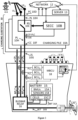
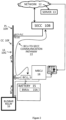
- FIG. 1 is a block diagram representing the system in an embodiment of the invention comprising a server 13, a network 12, a plurality of charging piles 10A, and a ferry 14. Details of FIG. 1 focused on the data communication of this same system are depicted in FIG. 2 . Details of FIG. 1 focused on the pathway of current from a utility provider 11 to the battery cells 15C are depicted in FIG. 3 .
- FIG. 1 depicts use of the invention with a ferry 14, the invention is applicable to any type of electrical vehicle benefiting from a multi-pile charging session. E.g., the invention can also be used for buses, trolleys, and trains.
- a charging substation includes three charging piles 10A.
- Each charging pile 10A (represented in FIG. 1 as the topmost represented charging pile 10A ) includes a power line 10H connected to a power connector 10D at a first end and a charging connector 10F at a second end. Between the power connector 10D and the charging connector 10F, the power line 10H includes a relay switch 10C controlled by a supply equipment communication controller (SECC) 10B.
- SECC supply equipment communication controller
- Each power connector 10D is connected electrically to a utility line ( UL 0 , UL 1 , UL 2 ), which are connected to the utility provider 11.
- the SECC 10B is in data communication with a server 13 through a network 12.
- the SECC 10B is also in data communication with the power line 10H through a charging pile power line communication module (hereafter "CP-PLC") 10E. While FIG. 1 depicts three charging piles 10A in the charging substation 10, the invention can use two or more charging piles 10A for each multi-pile charging session; these charging piles 10A can be located within the same charging sub-station 10 or in separate charging substations 10.
- CP-PLC charging pile power line communication module
- the electric vehicle of the invention is a ferry 14 with an electric motor 19 powering a ship propeller 20.
- the electric motor 19 is powered by the battery cells 15C of a battery 15, with a current passing: (i) from the battery cells 15C to a busbar relay 16 through a busbar battery trunk 16A; and (ii) from the busbar relay 16 to the electric motor 19 through a busbar engine trunk 16B.
- Charging current from a power line 10H of each charging pile 10A of the charging substation 10 passes into the ferry 14 from charging connector 10F of the charging pile 10A to the charging port ( CP 0 , CP 1 , CP 2 ) of ferry 14 through an umbilical line 10G.
- the battery 15 includes a plurality of battery management units (BMUs) 15A, a plurality of battery sensors 15B, and the battery cells 15C.
- the busbar relay 16 is in electrical communication with three busbar relay trunks ( BIT 0 , BIT 1 , BIT 2 ) connected at a first junction with the charging ports ( CP 0 , CP 1 , CP 2 ) and to the busbar relay 16 at a second junction.
- Each busbar input trunk ( BIT 0 , BIT 1 , BIT 2 ) is paired in data communication with a battery control unit (hereafter "BCU", identified in FIGs.
- BCU battery control unit
- a master battery control unit (MBCU) 18 is in data communication with the BMUs 15A and a plurality of battery control units.
- the MCBU 18 can be configured to be in data communication with the BMUs 15A via at least one BCU (illustrated in FIGs. 1 and 2 as BCU 0 ). While not illustrated in FIGs. 1 and 2 , the BMUs 15A can collect sensor information from the battery sensors 15B; the battery sensors 15B can be configured to monitor current, temperature, and other parameters of the battery cells 15C.
- each of the three illustrated BCUs ( BCU 0 , BCU 1 , BCU 2 ) is paired in data communication with one of the EV-PLCs ( PLC 0 , PLC 1 , and PLC 3 ) to establish a BCU-to-SECC communication pathway 22 for the BCU ( BCU 0 , BCU 1 , BCU 2 ) upon a connective pairing of the charging port ( CP 0 , CP 1 , CP 2 ) associated with the BCU ( BCU 0 , BCU 1 , BCU 2 ) and one of the charging connectors 10F.
- the charging port CP 0 , CP 1 , CP 2
- the BCU-to-SECC communication pathway 22 for each BCU passes from the BCU ( BCU 0 , BCU 1 , BCU 2 ) to the EV-PLC ( PLC 0 , PLC 1 , PLC 2 ) associated with the BCU ( BCU 0 , BCU 1 , BCU 2 ) , to the busbar input trunk ( BIT 0 , BIT 1 , BIT 2 ) associated with the EV-PLC ( PLC 0 , PLC 1 , PLC 2 ) , to the connectively paired charging port ( CP 0 , CP 1 , CP 2 ) associated with the busbar input trunk ( BIT 0 , BIT 1 , BIT 2 ), to the connectively paired charging connector 10F associated with the connectively paired charging port ( CP 0 , CP 1 , CP 2 ) , to the power line 10H associated with the connectively paired charging connector 10
- the SECC 10B also conducts communication with the server 13 through the network 12.
- the MBCU 18, which controls each BCU ( BCU 0 , BCU 1 , BCU 2 ) is in data communication with the BMUs 15A via at least one BCU (illustrated in FIGs. 1 and 2 as BCU 0 ), the busbar relay 16, and the user interface device 17. While FIG. 1 depicts three sets of BCU-to-SECC communication pathways 22, the invention can be implemented with two or more.
- FIG. 4 is a flowchart 4-00 of steps taken in an embodiment of the invention. Steps 4-01 to 4-08 are listed below. 4-01 conduct a safety check of the battery 15 from sensor information received by the MBCU 18 from the BMUs 15A and an insulation detection sensor of the busbar relay 16 4-02 establish a connective pairing of each of the charging connectors 10F and the charging ports ( CP 0 , CP 1 , CP 2 ) of the electric vehicle through separate umbilical lines 10G to create one BCU-to-SECC communication pathway 22 for each connective pairing 4-03 establish an independent protocol message exchange between the paired BCU ( BCU 0 , BCU 1 , BCU 2 ) and SECC 10B along each BCU-to-SECC communication pathway 22 4-04 delivery a vehicle identifier for the electric vehicle to the server 13 through each BCU-to-SECC communication pathway 22 with an authorization request for the independent charging session to obtain an authorization approval of the independent charging session 4-05 receive through each BCU-to-SECC communication pathway 22 a set of
- a first embodiment of the invention is a system for vehicle-side control of a multi-pile charging session, the system comprising: (a) a plurality of charging piles 10A; and (b) a vehicle electrical system for an electric vehicle.
- Each charging pile 10A comprises: (i) a power line 10H electrically connected to a power connector 10D at a first end and to a charging connector 10F at a second end; and (ii) a supply equipment communication controller (SECC) 10B.
- SECC supply equipment communication controller
- the power line 10H is connectable to a utility line ( UL 0 , UL 1 , UL 2 ) .
- the power line 10H includes a relay switch 10C positioned between the power connector 10D and the charging connector 10F.
- a charging pile power line communication module (CP-PLC) 10E is positioned adjacent the power line 10H between the relay switch 10C and the charging connector 10F.
- the SECC 10B is in data communication with the relay switch 10C and the CP-PLC 10E. Current is permitted to flow from the utility line ( UL 0 , UL 1 , UL 2 ) to the charging connector 10F through the power line 10H, upon activation of the relay switch 10C by the SECC 10B.
- the vehicle electrical system includes: (i) a battery 15 including a plurality of battery management units (BMUs) 15A and a plurality of battery cells 15C; (ii) a busbar relay 16 in electrical connection to the battery cells 15C via at least one busbar battery trunk 16A; (iii) a plurality of charging ports ( CP 0 , CP 1 , CP 2 ); (iv) a plurality of busbar input trunks ( BIT 0 , BIT 1 , BIT 2 ); and (v) a master battery control unit (MBCU) 18.
- Each charging port ( CP 0 , CP 1 , CP 2 ) is configured for electrical connection to the charging connector 10F of one of the charging piles 10A.
- the charging port ( CP 0 , CP 1 , CP 2 ) is directly electrically connected to the charging connector 10F or the charging port ( CP 0 , CP 1 , CP 2 ) is indirectly electrically connected to the charging connector 10F through an umbilical line 10G.
- Each busbar input trunk ( BIT 0 , BIT 1 , BIT 2 ) is electrically connected to one of the charging ports ( CP 0 , CP 1 , CP 2 ) at a first junction and to the busbar relay 16 at a second junction.
- Each busbar input trunk ( BIT 0 , BIT 1 , BIT 2 ) is in data communication with an electric vehicle power line communication module (EV-PLC) ( PLC 0 , PLC 1 , PLC 2 ) positioned adjacent the busbar input trunk ( BIT 0 , BIT 1 , BIT 2 ) between the charging port ( CP 0 , CP 1 , CP 2 ) associated with the busbar input trunk ( BIT 0 , BIT 1 , BIT 2 ) and the busbar relay 16.
- E-PLC electric vehicle power line communication module
- the MBCU 18 is in data communication with a plurality of battery control units (BCU) ( BCU 0 , BCU 1 , BCU 2 ), the BMUs 15A of the battery 15, the busbar relay 16, and a user interface device 17.
- BCU battery control units
- Each BCU ( BCU 0 , BCU 1 , BCU 2 ) is paired in data communication with one of the EV-PLCs ( PLC 0 , PLC 1 , PLC 2 ) to establish a BCU-to-SECC communication pathway 22 for the BCU ( BCU 0 , BCU 1 , BCU 2 ) upon a connective pairing of the charging port ( CP 0 , CP 1 , CP 2 ) associated with the BCU ( BCU 0 , BCU 1 , BCU 2 ) and one of the charging connectors 10F.
- BCU battery control units
- the BCU-to-SECC communication pathway 22 for each BCU passes from the BCU ( BCU 0 , BCU 1 , BCU 2 ) to the EV-PLC ( PLC 0 , PLC 1 , PLC 2 ) associated with the BCU( BCU 0 , BCU 1 , BCU 2 ), to the busbar input trunk ( BIT 0 , BIT 1 , BIT 2 ) associated with the EV-PLC ( PLC 0 , PLC 1 , PLC 2 ) , to the connectively paired charging port ( CP 0 , CP 1 , CP 2 ) associated with the busbar input trunk ( BIT 0 , BIT 1 , BIT 2 ), to the connectively paired charging connector 10F associated with the connectively paired charging port ( CP 0 , CP 1 , CP 2 ), to the power line 10H associated with the connectively paired charging connector 10F, to the
- the MBCU 18 is configured to: (a) coordinate two or more independent charging sessions during each multi-pile charging session to charge the battery cells 15C simultaneously through two or more charging ports ( CP 0 , CP 1 , CP 2 ) according to a multi-pile charging plan; and (b) manage each independent charging session with an independent protocol message exchange through each BCU-to-SECC communication pathway 22, from the BCU ( BCU 0 , BCU 1 , BCU 2 ) of the BCU-to-SECC communication pathway 22 to the SECC 10B of the BCU-to-SECC communication pathway 22.
- Each independent charging session includes an initiation stage, a charging stage, and a shutdown stage conducted through the associated BCU-to-SECC communication pathway 22.
- sensor information from the battery sensors 15B can be collected by the BMUs 15A.
- a second embodiment of the invention is a computer-implemented method for vehicle-side control of a multi-pile charging session, the method comprising the steps of: (a) maintaining a plurality of charging piles 10A; (b) maintaining a vehicle electrical system for an electric vehicle; (c) coordinating with the MBCU 18 two or more independent charging sessions during each multi-pile charging session to charge the battery cells 15C simultaneously through two or more charging ports ( CP 0 , CP 1 , CP 2 ) according to a multi-pile charging plan; and (d) managing with the MBCU 18 each independent charging session with an independent protocol message exchange through each BCU-to-SECC communication pathway 22, from the BCU ( BCU 0 , BCU 1 , BCU 2 ) of the BCU-to-SECC communication pathway 22 to the SECC of the BCU-to-SECC communication pathway 22, wherein each independent charging session includes an initiation stage, a charging stage, and a shutdown stage conducted through the associated BCU-to-SECC communication pathway 22.
- Each charging pile 10A includes: (i) a power line 10H electrically connected to a power connector 10D at a first end and to a charging connector 10F at a second end; and (ii) a supply equipment communication controller (SECC) 10B.
- the power line 10H is connectable to a utility line ( UL 0 , UL 1 , UL 2 ).
- the power line 10H includes a relay switch 10C positioned between the power connector 10D and the charging connector 10F.
- a charging pile power line communication module (CP-PLC) 10E is positioned adjacent the power line 10H between the relay switch 10C and the charging connector 10F.
- the SECC 10B is in data communication with the relay switch 10C and the CP-PLC 10E.
- the vehicle electrical system includes: (i) a battery 15 including a plurality of battery management units (BMUs) 15A and a plurality of battery cells 15C; and (ii) a busbar relay 16 in electrical connection to the battery cells 15C via at least one busbar battery trunk 16A; (iii) a plurality of charging ports ( CP 0 , CP 1 , CP 2 ); (iv) a plurality of busbar input trunks ( BIT 0 , BIT 1 , BIT 2 ); and (v) a master battery control unit (MBCU) 18.
- BMUs battery management units
- a busbar relay 16 in electrical connection to the battery cells 15C via at least one busbar battery trunk 16A
- a plurality of charging ports CP 0 , CP 1 , CP 2
- a plurality of busbar input trunks BIT 0 , BIT 1 , BIT 2
- MBCU master battery control unit
- Each charging port ( CP 0 , CP 1 , CP 2 ) is configured for electrical connection to the charging connector 10F of one of the charging piles 10A.
- the charging port ( CP 0 , CP 1 , CP 2 ) is directly electrically connected to the charging connector 10F or the charging port ( CP 0 , CP 1 , CP 2 ) is indirectly electrically connected to the charging connector 10F through an umbilical line 10G.
- Each busbar input trunk ( BIT 0 , BIT 1 , BIT 2 ) is electrically connected to one of the charging ports ( CP 0 , CP 1 , CP 2 ) at a first junction and to the busbar relay 16 at a second junction.
- Each busbar input trunk ( BIT 0 , BIT 1 , BIT 2 ) is in data communication with an electric vehicle power line communication module (EV-PLC) ( PLC 0 , PLC 1 , PLC 2 ) positioned adjacent the busbar input trunk ( BIT 0 , BIT 1 , BIT 2 ) between the charging port ( CP 0 , CP 1 , CP 2 ) associated with the busbar input trunk ( BIT 0 , BIT 1 , BIT 2 ) and the busbar relay 16.
- E-PLC electric vehicle power line communication module
- the MBCU 18 is in data communication with a plurality of battery control units (BCU) ( BCU 0 , BCU 1 , BCU 2 ), the BMUs 15A of the battery 15, the busbar relay 16, and a user interface device 17.
- BCU battery control units
- Each BCU ( BCU 0 , BCU 1 , BCU 2 ) is paired in data communication with one of the EV-PLCs ( PLC 0 , PLC 1 , PLC 2 ) to establish a BCU-to-SECC communication pathway 22 for the BCU ( BCU 0 , BCU 1 , BCU 2 ) upon a connective pairing of the charging port ( CP 0 , CP 1 , CP 2 ) associated with the BCU ( BCU 0 , BCU 1 , BCU 2 ) and one of the charging connectors 10F.
- BCU battery control units
- the BCU-to-SECC communication pathway 22 for each BCU passes from the BCU ( BCU 0 , BCU 1 , BCU 2 ) to the EV-PLC ( PLC 0 , PLC 1 , PLC 2 ) associated with the BCU ( BCU 0 , BCU 1 , BCU 2 ) , to the busbar input trunk ( BIT 0 , BIT 1 , BIT 2 ) associated with the EV-PLC ( PLC 0 , PLC 1 , PLC 2 ), to the connectively paired charging port ( CP 0 , CP 1 , CP 2 ) associated with the busbar input trunk ( BIT 0 , BIT 1 , BIT 2 ), to the connectively paired charging connector 10F associated with the connectively paired charging port ( CP 0 , CP 1 , CP 2 ), to the power line 10H associated with the connectively paired charging connector 10F, to the
- sensor information from the battery sensors 15B can be collected by the BMUs 15A.
- the user interface device 17 is integrated into a vehicle control unit of the electric vehicle.
- the vehicle control unit would of a ferry 14, for instance, would typically be on the bridge of the ferry 14.
- the multi-pile charging session is conducted without any data communication between the charging piles 10A utilized in the multi-pile charging session.
- a multi-pile charging session can, for instance, be implemented using charging piles 10A from different charging substations 10.
- the multi-pile charging session can also be conducting using independent charging sessions authorized by separate vendors via communication with separate servers 13.
- the busbar sensors can alternatively also include at least one of: (a) an insulation detection sensor; (b) a current meter; and (c) a temperature sensor.
- the MBCU 18 uses the MBCU 18 to both manage the multi-pile charging session and the critical sensors used for safety checks/assessment provides the capability of a faster response to emerging safety issues.
- the MBCU 18 has data communication both with each of the charging piles 10A through the BCUs ( BCU 0 , BCU 1 , BCU 2 ) as well as access to important sensors in the battery 15 and busbar relay 16, thus the MBCU 18 is well-positioned to initiate emergency shut-down of any independent charging session should the need arise.
- the embodiment further includes or maintains a server 13 in data communication with the SECC 10B of each charging pile 10A through a network 12, the server 13 including a database comprising a plurality of vehicle records and a plurality of meter records.
- Each vehicle record includes, for each of a plurality of vehicles, a vehicle identifier and an account status.
- Each meter record identifies at least one vehicle identifier and a charging session summary for each multi-pile charging session.
- the independent protocol message exchange conducted through the BCU-to-SECC communication pathway 22 can alternatively include: (a) delivery of the vehicle identifier of the electric vehicle from the BCU ( BCU 0 , BCU 1 , BCU 2 ) to the SECC 10B; (b) return delivery of the authorization approval of the independent charging session from the SECC 10B to the BCU ( BCU 0 , BCU 1 , BCU 2 ); and (c) delivery of a set of parameters for the charging pile 10A associated with the BCU-to-SECC communication pathway 22, each set of parameters including an output voltage range and a maximum transfer current.
- the SECC 10B forwards the vehicle identifier to the server 13 with an authorization request for the independent charging session.
- the server 13 accesses the account status of the vehicle record associated with the vehicle identifier to, if so authorized, issue an authorization approval for the independent charging session.
- the server 13 return delivers the authorization approval to the SECC 10B.
- the independent protocol message exchange conducted through the BCU-to-SECC communication pathway 22 during the initiation stage further includes the delivery of a charging port ( CP 0 , CP 1 , CP 2 ) identifier for the BCU-to-SECC communication pathway 22.
- Each vehicle record in the database further includes two or more charging port identifiers for the electric vehicle.
- the charging session summary for each multi-pile charging session includes a listing of the charging port identifiers for the charging piles 10A utilized in the multi-pile charging session.
- the embodiment further includes or maintains a server 13 in data communication with the SECC 10B of each charging pile 10A through a network 12, the server 13 including a database comprising a plurality of vehicle records and a plurality of meter records.
- Each vehicle record includes, for each of a plurality of vehicles, a vehicle identifier and an account status.
- Each meter record identifies at least one vehicle identifier and a charging session summary for each multi-pile charging session.
- the independent protocol message exchange conducted through the BCU-to-SECC communication pathway 22 can alternatively include: (a) delivery of the vehicle identifier of the electric vehicle from the BCU ( BCU 0 , BCU 1 , BCU 2 ) to the SECC 10B; (b) return delivery of the authorization approval of the independent charging session from the SECC 10B to the BCU ( BCU 0 , BCU 1 , BCU 2 ); and (c) delivery of a set of parameters for the charging pile 10A associated with the BCU-to-SECC communication pathway 22, each set of parameters including an output voltage range and a maximum transfer current.
- the SECC 10B forwards the vehicle identifier to the server 13 with an authorization request for the independent charging session.
- the server 13 accesses the account status of the vehicle record associated with the vehicle identifier to, if so authorized, issue an authorization approval for the independent charging session.
- the server 13 return delivers the authorization approval to the SECC 10B.
- the user interface device 17 is in data communication with the server 13 through the network 12.
- the user interface device is configured to assemble the multi-pile charging plan from at least one of (i) a custom charging plan; (ii) a preconfigured charging plan for the charging piles 10A, wherein the preconfigured charging plan is accessible from the server 13 through the user interface device; and (iii) a prior multi-pile charging plan previously successfully performed by the electric vehicle.
- the custom charging plan is calculated from: (1) the sets of parameters received from the charging piles 10A associated with the BCU-to-SECC communication pathways 22 successfully completing the initiation stage, including the output voltage range and the maximum transfer current for each charging pile 10A; (2) a starting power storage of the battery 15; (3) a target power storage of the battery 15; and (4) a set of safety limits for the vehicle electrical system.
- the embodiment further includes or maintains a server 13 in data communication with the SECC 10B of each charging pile 10A through a network 12, the server 13 including a database comprising a plurality of vehicle records and a plurality of meter records.
- Each vehicle record includes, for each of a plurality of vehicles, a vehicle identifier and an account status.
- Each meter record identifies at least one vehicle identifier and a charging session summary for each multi-pile charging session.
- the independent protocol message exchange conducted through the BCU-to-SECC communication pathway 22 can alternatively include: (a) delivery of the vehicle identifier of the electric vehicle from the BCU ( BCU 0 , BCU 1 , BCU 2 ) to the SECC 10B; (b) return delivery of the authorization approval of the independent charging session from the SECC 10B to the BCU ( BCU 0 , BCU 1 , BCU 2 ); and (c) delivery of a set of parameters for the charging pile 10A associated with the BCU-to-SECC communication pathway 22, each set of parameters including an output voltage range and a maximum transfer current.
- the SECC 10B forwards the vehicle identifier to the server 13 with an authorization request for the independent charging session.
- the server 13 accesses the account status of the vehicle record associated with the vehicle identifier to, if so authorized, issue an authorization approval for the independent charging session.
- the server 13 return delivers the authorization approval to the SECC 10B.
- the user interface device is in data communication with the server 13 through the network 12.
- the user interface device is configured to assemble the multi-pile charging plan from at least one of (i) a custom charging plan; (ii) a preconfigured charging plan for the charging piles 10A, wherein the preconfigured charging plan is accessible from the server 13 through the user interface device; and (iii) a prior multi-pile charging plan previously successfully performed by the electric vehicle.
- the custom charging plan is calculated from: (1) the sets of parameters received from the charging piles 10A associated with the BCU-to-SECC communication pathways 22 successfully completing the initiation stage, including the output voltage range and the maximum transfer current for each charging pile 10A; (2) a starting power storage of the battery 15; (3) a target power storage of the battery 15; and (4) a set of safety limits for the vehicle electrical system.
- a safety simulation of the multi-pile charging plan is conducted by the user interface device or the server 13 prior to the charging stage.
- Each multi-pile charging plan includes an emergency shutdown protocol.
- Commencement of the charging stage requires prior review and authorization through the user interface device of the multi-pile charging plan by an authenticated user of the electric vehicle.
- the user interface device or the server 13 stores a sensor information log for each multi-pile charging session.
- the authorization approval could be established, for instance, by requiring a login and password of the ferry captain or other trained officer of the ferry 14 to ensure proper compliance with billing and/or safety procedures of the ferry 14.
- AI / ML can be used to improve future multi-pile charging plans by analysing sensor log details from electric vehicles during previous multi-pile charging sessions.
Landscapes
- Engineering & Computer Science (AREA)
- Power Engineering (AREA)
- Transportation (AREA)
- Mechanical Engineering (AREA)
- Charge And Discharge Circuits For Batteries Or The Like (AREA)
- Electric Propulsion And Braking For Vehicles (AREA)
Description
- The present disclosure relates to electric vehicle charging. More particularly, the present disclosure relates to vehicle-side control of a multi-pile charging session comprising independent charging sessions.
- Charging piles of a charging substation are used for the controlled transfer of electrical power to electrical vehicles during charging sessions. Charging piles can be used in a commercial setting, wherein customers use the charging pile to charge their electric vehicle at a charging facility hosting one or more charging substations. To effect billing and authorization of each charging session, the charging piles are often in data communication with a server through a network. The server typically includes a database including vehicle records for the customers and meter records documenting each charging session performed by the charging piles. During the initiation stage of the charging session, a vehicle identifier for the electric vehicle is typically sent to the server. In the shutdown stage of the charging session, the final power delivery totals are stored in the meter records of the server's database. The server is thereafter accessed by the vendor to conduct customer billing procedures for charging sessions.
- Charging ports on the electric vehicles are connected to charging connectors of the charging pile, often through an umbilical line spanning the distance therebetween. Industry standards typically dictate: (i) dimensions of the charging connectors and charging ports; (ii) voltage ranges for the charging piles; and (iii) current ranges for the charging piles. Widely implemented industry standards for the charging piles and initiation of separate charging sessions are included within ISO 15118/DIN 70121 and the national standard GB/T27930-2015. Charging piles following these standards can be used for many types of electric vehicles (typically passenger cars, buses, ferries, trolleys, and trains).
- Use of a single charging pile may be sufficient for the charging session of a passenger car. But larger electric vehicles such as buses, ferries, trolleys, and trains require significant power transfer to their on-board battery which cannot be supplied in a reasonable time by a single charging pile. Each charging pile has by itself a limited power transfer rate (related to its maximum voltage and current range), therefore larger electric vehicles are often charged simultaneously from multiple charging piles housed in a charging substation. These charging sessions simultaneously using multiple charging piles are often called dual-gun charging sessions, multiple-gun charging sessions, or multi-pile charging sessions.
- An example publication for multi-pile charging sessions is Chinese Patent Application No.
CN109760545A, dated 17 May 2019 and entitled "Charging Method and Charging Device". This publication describes the use of multiple charging piles of a charging substation to simultaneously charge an electric vehicle in a multi-pile charging session. One of the charging piles of the charging substation is designated the master charging pile. The master charging pile of the charging substation controls both its own charging session and the charging sessions of the other charging piles (designated "slave" charging piles) of the same charging substation. Hence, coordination of the separate charging sessions for each of the charging piles of the charging substation is performed by the master charging pile of the charging substation. WhileCN109760545A presents a method to coordinate the multi-pile charging session, it requires both a hardware modification (e.g., dedicated communication lines between each of the charging piles of the charging substation) and a software modification to the standardized communication protocols (e.g., to override the need for specific protocol messaging between the electric vehicle and the slave charging pile through the slave charging port). - This need for dedicated hardware communication links and software driven coordination between charging piles of a charging substation in the prior art can lead to compatibility issues. As a first matter, issues with incompatibility between legacy charging piles and newly acquired charging piles in the same charging substation are likely to arise over time, even if equipment initially purchased for the charging substation was fully functional at the time of initial set up. For instance, the newly purchased equipment may be a different model number or purchased from a different manufacturer entirely.
- As a second matter, in the event of malfunction of one charging pile, the operation of other charging piles may also be affected due to communication error signals. For instance, faults detected during initiation of the charging piles of the charging substation could halt the entire multi-pile charging session.
- As a third matter, a large charging facility may support multiple charging substations operated by different vendors. These multiple charging substations may be unconnected to each other. The master/slave protocols of the prior art assumes that the master charging pile and the slave charging pile are operated by the same vendor (and hence only require a single authorization from the vendor routed through the master charging pile). Thus, an electric vehicle would be unable to perform a multi-pile charging session using charging piles selected from the charging substations of multiple vendors located at the same charging facility.
- What is needed therefore is a system and method for conducting multi-pile charging sessions with charging piles operating under the unmodified standardized communication protocols such that there is no need for either: (i) a set of dedicated communication lines between each of the charging piles; or (ii) any software driven coordination between the charging piles of the charging substation.
-
US2020/122593A1, Noh et, al entitled "Vehicle and Method for Controlling the same" discloses a vehicle and a method for controlling the vehicle. The vehicle may include multiple charging ports electrically coupled to a first connector and a second connector. Each of the first and second connectors is configured to receive power from one or more charger; and a controller is configured to receive a charging start command and, upon receiving the charging start command, to control operation of the vehicle to be sequentially paired with the first connector and the second connector when the first connector and the second connector are electrically coupled to the multiple charging ports. -
WO2011/062037A1, Anegawa et al entitled "Charging System, Charger, Electric Movable Body, and Method for Charging Battery for Electric Movable Body" discloses a technique that is capable of more reliably starting and completing a charging control sequence even when a communication error occurs due to noise and that is also capable of reliably opening a relay except for during charging. In addition to charging lines used for supplying charging power from a charger to an electric vehicle and communication lines used for exchanging a charging current specification value between the charger and the electric! vehicle, there are provided driving power supply lines used for supplying driving power from a control-system power supply to a relay disposed between the charging line and an in-vehicle battery. By controlling the conduction patterns of the driving power supply line not only the relay is opened or closed, but also the starting and completion signals of a charging control sequence are exchanged between the charger and the electric vehicle. -
US2013/041531A1, Lafrance , entitled "Vehicle Controllers and Methods for use in charging an electrically powered vehicle" discloses methods and vehicle controllers for use in charging an electrically powered vehicle. One example vehicle controller includes a memory device configured to store a user-profile and a processor electrically coupled to the memory device. The processor is programmed to detect a vehicle charging station, retrieve the user profile from the memory device, and communicate the user profile to the vehicle charging station. The user profile includes billing information. -
WO2018/190796A1, Rebele et al, entitled "Battery Fleet Charging System" discloses a battery fleet charging system for charging one or more batteries simultaneously at independently controlled charge rates. The disclosed charging system can intelligently distribute an available charging power among multiple battery chargers, either symmetrically or asymmetrically. as specified by a central controller to regulate the power used by each battery charger. -
US2018/0304759A1, Chase et al, entitled "Intelligent Vehicle Charging Equipment" discloses an intelligent vehicle charging system for charging a fleet of autonomous vehicles throughout a network of charging stations dispersed throughout a geographic area. The intelligent vehicle charging system includes a remote control system that is in operative communication with each of the autonomous vehicles in the fleet and each of the charging stations in the network. When an autonomous vehicle is in need of a power charge, or as directed by the remote control system, the remote control system will identify an available charging station, guide the autonomous vehicle to the charging station, verify that the autonomous vehicle has arrived at the charging station, initiate the power charging process, account and bill appropriate fees for the charging process, and log all associated activity. The remote control system is also capable of remotely and instantaneously terminating the power charging process to dynamically return a vehicle back to service. -
CN 108248434A , entitled "Electric vehicle charge control method and device" discloses a charging control method and device for an electric vehicle. The electric vehicle includes two charging interfaces. The two charging interfaces are used to connect to two charging guns of a charging pile. And the two charging interfaces are respectively connected to a battery management system through two CAN lines. The method includes detecting whether the two charging guns of the charging pile are physically connected to the two charging interfaces. If so, the method includes establishing a communication connection between the battery management system and the charging pile through the two CAN lines: sending the charging demand to the charging pile through the two CAN lines so that the charging pile can simultaneously charge the electric vehicle through the two charging guns according to the charging demand. The charging requirements include at least charging voltage requirements and charging current requirements. The two charging guns of the charging pile can be controlled to simultaneously charge the same electric vehicle through the two CAN lines, which solves the problem of slow charging. -
US2011/241824A1, Uesugi , entitled "IN-vehicle Mount Type Battery Charging System, Managing Server, Managing Server Control Method and Computer-readable Medium Storing Program for Managing Server" discloses an in-vehicle mount type battery charging system including a charging station having a charger for charging an in-vehicle mount battery of an electric vehicle, and a managing server connected to the charger. The managing server receives registration for enabling use of the charger from a user, authenticates the user when the user uses the charger and allows the user to use the charger when the user is authenticated as a registered member. Furthermore, the managing server receives temporary registration for temporarily enabling use of the charger from a user as a nonmember, authenticates the user when the user uses the charger and temporarily allows the user to use the charger when the user is authenticated as a registered temporary member. -
US2020/125052, Jeong , entitled "Power Supply Apparatus and System, and Method for using the same" discloses a power supply apparatus for supplying power to an external electric device. The power supply apparatus includes a power outlet unit to which a power plug of the external electric device is coupled, to supply electricity to the external electric device; a power control unit controlling power supply from the power outlet unit to the external electric device; and a user interface unit connected to the power control unit to receive a power activation code from a user, wherein the power control unit supplies power from the power outlet unit to the external electric device during a usage period, corresponding to the power activation code. - In its most general form, the invention is a system or method for vehicle-side control of a multi-pile charging session, the system comprising: (a) a plurality of charging piles, each charging pile including a supply equipment communication controller (SECC); and (b) a vehicle electrical system for an electric vehicle with a master battery control unit (MBCU) in data communication with a plurality of battery control units (BCU). The MBCU is configured to coordinate two or more independent charging sessions through the BCUs during each multi-pile charging session. Each independent charging session is managed with an independent protocol message exchange through a BCU-to-SECC communication pathway.
- In more detail, a first embodiment of the invention is a system for vehicle-side control of a multi-pile charging session, the system comprising: (a) a plurality of charging piles; and (b) a vehicle electrical system for an electric vehicle. Each charging pile comprises: (i) a power line electrically connected to a power connector at a first end and to a charging connector at a second end; and (ii) a supply equipment communication controller (SECC). The power line is connectable to a utility line. The power line includes a relay switch positioned between the power connector and the charging connector. A charging pile power line communication module (CP-PLC) is positioned adjacent the power line between the relay switch and the charging connector. The SECC is in data communication with the relay switch and the CP-PLC. Current is permitted to flow from the utility line to the charging connector through the power line, upon activation of the relay switch by the SECC. The vehicle electrical system includes: (i) a battery including a plurality of battery management units (BMUs) and a plurality of battery cells; (ii) a busbar relay in electrical connection to the battery cells via at least one busbar battery trunk; (iii) a plurality of charging ports; (iv) a plurality of busbar input trunks; and (v) a master battery control unit (MBCU). Each charging port is configured for electrical connection to the charging connector of one of the charging piles. The charging port is directly electrically connected to the charging connector or the charging port is indirectly electrically connected to the charging connector through an umbilical line. Each busbar input trunk is electrically connected to one of the charging ports at a first junction and to the busbar relay at a second junction. Each busbar input trunk is in data communication with an electric vehicle power line communication module (EV-PLC) positioned adjacent the busbar input trunk between the charging port associated with the busbar input trunk and the busbar relay. The MBCU is in data communication with a plurality of battery control units (BCU), the BMUs of the battery, the busbar relay, and a user interface device. Each BCU is paired in data communication with one of the EV-PLCs to establish a BCU-to-SECC communication pathway for the BCU upon a connective pairing of the charging port associated with the BCU and one of the charging connectors. The BCU-to-SECC communication pathway for each BCU passes from the BCU to the EV-PLC associated with the BCU, to the busbar input trunk associated with the EV-PLC, to the connectively paired charging port associated with the busbar input trunk, to the connectively paired charging connector associated with the connectively paired charging port, to the power line associated with the connectively paired charging connector, to the CP-PLC associated with the power line, and to the SECC associated with the CP-PLC. The MBCU is configured to: (a) coordinate two or more independent charging sessions during each multi-pile charging session to charge the battery cells simultaneously through two or more charging ports according to a multi-pile charging plan; and (b) manage each independent charging session with an independent protocol message exchange through each BCU-to-SECC communication pathway, from the BCU of the BCU-to-SECC communication pathway to the SECC of the BCU-to-SECC communication pathway. Each independent charging session includes an initiation stage, a charging stage, and a shutdown stage conducted through the associated BCU-to-SECC communication pathway; and wherein during the initiation stage of each independent charging session, the independent protocol message exchange conducted through the BCU-to-SECC communication pathway includes: delivery of the vehicle identifier of the electric vehicle from the BCU to the SECC, wherein the SECC forwards the vehicle identifier to the server with an authorization request for the independent charging session; wherein the server accesses the account status of the vehicle record associated with the vehicle identifier to, if so authorized, issue an authorization approval for the independent charging session; and wherein the server return delivers the authorization approval to the SECC; delivery of a charging port identifier for the BCU-to-SECC communication pathway; return delivery of the authorization approval of the independent charging session from the SECC to the BCU; and delivery of a set of parameters for the charging pile associated with the BCU-to-SECC communication pathway, each set of parameters including an output voltage range and a maximum transfer current; and (c) a server in data communication with the SECC of each charging pile through a network, the server including a database comprising a plurality of vehicle records and a plurality of meter records, (i) wherein each vehicle record includes, for each of a plurality of vehicles, a vehicle identifier, an account status and two or more charging port identifiers for the electric vehicle; (ii) wherein each meter record identifies at least one vehicle identifier and a charging session summary for each multi-pile charging session; and (iii) wherein the charging session summary for each multi-pile charging session includes a listing of the charging port identifiers for the charging piles utilized in the multi-pile charging session.
- A second embodiment of the invention is a computer-implemented method for vehicle-side control of a multi-pile charging session, the method comprising the steps of: (a) maintaining a plurality of charging piles; (b) maintaining a vehicle electrical system for an electric vehicle; (c) coordinating with the MBCU two or more independent charging sessions during each multi-pile charging session to charge the battery cells simultaneously through two or more charging ports according to a multi-pile charging plan; and (d) managing with the MBCU each independent charging session with an independent protocol message exchange through each BCU-to-SECC communication pathway, from the BCU of the BCU-to-SECC communication pathway to the SECC of the BCU-to-SECC communication pathway, wherein each independent charging session includes an initiation stage, a charging stage, and a shutdown stage conducted through the associated BCU-to-SECC communication pathway. Each charging pile includes: (i) a power line electrically connected to a power connector at a first end and to a charging connector at a second end; and (ii) a supply equipment communication controller (SECC). The power line is connectable to a utility line. The power line includes a relay switch positioned between the power connector and the charging connector. A charging pile power line communication module (CP-PLC) is positioned adjacent the power line between the relay switch and the charging connector. The SECC is in data communication with the relay switch and the CP-PLC. Current is permitted to flow from the utility line to the charging connector through the power line, upon activation of the relay switch by the SECC. The vehicle electrical system includes: (i) a battery including a plurality of battery management units (BMUs) and a plurality of battery cells; and (ii) a busbar relay in electrical connection to the battery cells via at least one busbar battery trunk; (iii) a plurality of charging ports; (iv) a plurality of busbar input trunks; and (v) a master battery control unit (MBCU). Each charging port is configured for electrical connection to the charging connector of one of the charging piles. The charging port is directly electrically connected to the charging connector or the charging port is indirectly electrically connected to the charging connector through an umbilical line. Each busbar input trunk is electrically connected to one of the charging ports at a first junction and to the busbar relay at a second junction. Each busbar input trunk is in data communication with an electric vehicle power line communication module
- (EV-PLC) positioned adjacent the busbar input trunk between the charging port associated with the busbar input trunk and the busbar relay. The MBCU is in data communication with a plurality of battery control units (BCU), the BMUs of the battery, the busbar relay, and a user interface device. Each BCU is paired in data communication with one of the EV-PLCs to establish a BCU-to-SECC communication pathway for the BCU upon a connective pairing of the charging port associated with the BCU and one of the charging connectors. The BCU-to-SECC communication pathway for each BCU passes from the BCU to the EV-PLC associated with the BCU, to the busbar input trunk associated with the EV-PLC, to the connectively paired charging port associated with the busbar input trunk, to the connectively paired charging connector associated with the connectively paired charging port, to the power line associated with the connectively paired charging connector, to the CP-PLC associated with the power line, and to the SECC associated with the CP-PLC; wherein during the initiation stage of each independent charging session, the independent protocol message exchange conducted through the BCU-to-SECC communication pathway includes: delivery of the vehicle identifier of the electric vehicle from the BCU to the SECC, wherein the SECC forwards the vehicle identifier to the server with an authorization request for the independent charging session; wherein the server accesses the account status of the vehicle record associated with the vehicle identifier to, if so authorized, issue an authorization approval for the independent charging session; and wherein the server return delivers the authorization approval to the SECC; delivery of a charging port identifier for the BCU-to-SECC communication pathway; return delivery of the authorization approval of the independent charging session from the SECC to the BCU; and delivery of a set of parameters for the charging pile associated with the BCU-to-SECC communication pathway, each set of parameters including an output voltage range and a maximum transfer current; (e) maintaining a server in data communication with the SECC of each charging pile through a network, the server including a database comprising a plurality of vehicle records and a plurality of meter records, wherein each vehicle record includes, for each of a plurality of vehicles, a vehicle identifier, an account status and two or more charging port identifiers for the electric vehicle; wherein each meter record identifies at least one vehicle identifier and a charging session summary for each multi-pile charging session; and wherein the charging session summary for each multi-pile charging session includes a listing of the charging port identifiers for the charging piles utilized in the multi-pile charging session.
- Technical objects of the invention include: (a) coordination of independent charging sessions of a multi-pile charging sessions without need of a dedicated communication line between each of the charging piles of the charging substation; and (b) coordination of independent charging sessions of a multi-pile charging sessions without need of specialized software protocols in the charging substation enabling master/slave coordination during multi-pile charging sessions. Hence, the invention enables multi-pile charging sessions using standard infrastructure (e.g., independent charging sessions conducted by the charging piles of a charging substations that have not be modified to enable coordination of multi-pile charging sessions using hardware and software modifications diverging from the industry standard).
- The invention overcomes the need for compatibility between legacy charging piles and newly acquired charging piles installed on the same charging substation. The invention only requires the basic compliance of the charging piles with the industry standards. No communication or coordination between the charging piles is required within the charging substation. Charging piles purchased from different vendors or a mixture of charging pile model numbers will not affect the performance of the invention.
- The invention is also better able to overcome malfunctions of one of the charging piles of a charging substation. The invention separately initializes the BCU-to-SECC communication pathway of each independent charging session using an independent protocol message exchange. This approach reduces the interdependencies between the charging piles. Each charging pile of the charging substation is only required to maintain minimum compliance with the industry standard. If one charging pile of a charging substation malfunctions and cannot comply with the industry standard, then another charging pile from the charging substation (or even another charging substation) can be swapped in to replace the malfunctioning charging pile.
- The invention also supports multi-pile charging sessions using charging piles from different charging substations. For instance, with the invention, a first independent charging session of a multi-pile charging session can be initialized from a first vendor through a first customer account hosted by a first server through a first charging pile of a first charging substation. A second independent charging session of a multi-pile charging session can be initialized from a second vendor through a second customer account (for the same customer) hosted by a second server through a second charging pile of a second charging substation.
- Hence, the invention represents and improvement over the prior art by: (a) reducing the impact of incompatibility issues between legacy charging piles and newly acquired charging piles; (b) reducing the impact of a malfunction of one of the charging piles of charging substation upon a multi-pile charging session; and (c) enabling use of charging piles from separate charging sub-stations of a charging facility, even where those charging sub-stations are managed by different vendors.
- Embodiments of the present disclosure are described herein with reference to the drawings in which:
-
FIG. 1 is a block diagram representing the system in an embodiment of the invention. -
FIG. 2 is a simplified block diagram representing the system in an embodiment of the invention with focus on the BCU-to-SECC communication pathway. -
FIG. 3 is a simplified block diagram representing the system in an embodiment of the invention with focus on the electrical power transfer pathways between a charging pile and an electric vehicle. -
FIG.4 is a flowchart of steps taken in an embodiment of the invention. - In the following detailed description, reference is made to the accompanying drawings, which form a part hereof. The illustrative embodiments described in the detailed description, drawings and claims are not meant to be limiting. Other embodiments can be utilized, and other changes can be made, without departing from the spirit or scope of the subject matter presented herein. Unless specified otherwise, the terms "comprising," "comprise," "including" and "include" used herein, and grammatical variants thereof, are intended to represent "open" or "inclusive" language such that they include recited elements but also permit inclusion of additional, un-recited elements.
- As used herein, the software and hardware of a "server" may be implemented within: a single stand-alone computer, a stand-alone server, multiple dedicated servers, and/or a virtual server running on a larger network of servers and/or a cloud-based service. As used herein, a "database" may store data to and access data from a single stand-alone computer, a data server, multiple dedicated data servers, a cloud-based service, and/or a virtual server running on a network of servers.
- As used herein, a "user interface device" may be implemented by a display monitor, a keyboard, a mouse, a touch screen, a touch pad, and/or a computing device including a processor and software. The user interface device may be configured as a laptop, a smart phone, a tablet, a single stand-alone computer, or a customized user interaction device of a vehicle control unit.
-
FIG. 1 is a block diagram representing the system in an embodiment of the invention comprising aserver 13, anetwork 12, a plurality of chargingpiles 10A, and aferry 14. Details ofFIG. 1 focused on the data communication of this same system are depicted inFIG. 2 . Details ofFIG. 1 focused on the pathway of current from autility provider 11 to thebattery cells 15C are depicted inFIG. 3 . - Note that while
FIG. 1 depicts use of the invention with aferry 14, the invention is applicable to any type of electrical vehicle benefiting from a multi-pile charging session. E.g., the invention can also be used for buses, trolleys, and trains. - As depicted in
FIG. 1 , a charging substation includes three chargingpiles 10A. Each chargingpile 10A (represented inFIG. 1 as the topmost represented chargingpile 10A) includes apower line 10H connected to apower connector 10D at a first end and a chargingconnector 10F at a second end. Between thepower connector 10D and the chargingconnector 10F, thepower line 10H includes arelay switch 10C controlled by a supply equipment communication controller (SECC) 10B. Eachpower connector 10D is connected electrically to a utility line (UL0, UL1 , UL2 ), which are connected to theutility provider 11. TheSECC 10B is in data communication with aserver 13 through anetwork 12. TheSECC 10B is also in data communication with thepower line 10H through a charging pile power line communication module (hereafter "CP-PLC") 10E. WhileFIG. 1 depicts three chargingpiles 10A in the chargingsubstation 10, the invention can use two ormore charging piles 10A for each multi-pile charging session; these chargingpiles 10A can be located within thesame charging sub-station 10 or inseparate charging substations 10. - As depicted in
FIG. 1 andFIG. 3 the electric vehicle of the invention is aferry 14 with anelectric motor 19 powering aship propeller 20. Theelectric motor 19 is powered by thebattery cells 15C of abattery 15, with a current passing: (i) from thebattery cells 15C to abusbar relay 16 through abusbar battery trunk 16A; and (ii) from thebusbar relay 16 to theelectric motor 19 through abusbar engine trunk 16B. Charging current from apower line 10H of each chargingpile 10A of the chargingsubstation 10 passes into theferry 14 from chargingconnector 10F of the chargingpile 10A to the charging port (CP0 , CP1 , CP2 ) offerry 14 through anumbilical line 10G. Thebattery 15 includes a plurality of battery management units (BMUs) 15A, a plurality of battery sensors 15B, and thebattery cells 15C. Thebusbar relay 16 is in electrical communication with three busbar relay trunks (BIT0 , BIT1 , BIT2) connected at a first junction with the charging ports (CP0 , CP1 , CP2 ) and to thebusbar relay 16 at a second junction. Each busbar input trunk (BIT0 , BIT1 , BIT2) is paired in data communication with a battery control unit (hereafter "BCU", identified inFIGs. 1-2 as BCU0, BCU1, and BCU2 ) through an electric vehicle power line communication module (hereafter "EV-PLC", identified inFIGs. 1-2 as PLC0, PLC1 , PLC2 ). A master battery control unit (MBCU) 18 is in data communication with the BMUs 15A and a plurality of battery control units. TheMCBU 18 can be configured to be in data communication with the BMUs 15A via at least one BCU (illustrated inFIGs. 1 and2 as BCU0 ). While not illustrated inFIGs. 1 and2 , the BMUs 15A can collect sensor information from the battery sensors 15B; the battery sensors 15B can be configured to monitor current, temperature, and other parameters of thebattery cells 15C. - As most simply depicted in
FIG 2 , each of the three illustrated BCUs (BCU0 , BCU1, BCU2 ) is paired in data communication with one of the EV-PLCs (PLC0 , PLC1 , and PLC3 ) to establish a BCU-to-SECC communication pathway 22 for the BCU (BCU0 , BCU1, BCU2) upon a connective pairing of the charging port (CP0 , CP1, CP2 ) associated with the BCU (BCU0 , BCU1 , BCU2 ) and one of the chargingconnectors 10F. The BCU-to-SECC communication pathway 22 for each BCU (BCU0 , BCU1, BCU2) passes from the BCU (BCU0 , BCU1 , BCU2) to the EV-PLC (PLC0 , PLC1 , PLC2) associated with the BCU (BCU0 , BCU1, BCU2), to the busbar input trunk (BIT0 , BIT1 , BIT2 ) associated with the EV-PLC (PLC0 , PLC1 , PLC2), to the connectively paired charging port (CP0 , CP1 , CP2 ) associated with the busbar input trunk (BIT0 , BIT1 , BIT2 ), to the connectively paired chargingconnector 10F associated with the connectively paired charging port (CP0 , CP1, CP2), to thepower line 10H associated with the connectively paired chargingconnector 10F, to the CP-PLC 10E associated with thepower line 10H, and to theSECC 10B associated with the CP-PLC 10E. TheSECC 10B also conducts communication with theserver 13 through thenetwork 12. Note that theMBCU 18, which controls each BCU (BCU0 , BCU1, BCU2 ), is in data communication with the BMUs 15A via at least one BCU (illustrated inFIGs. 1 and2 as BCU0 ), thebusbar relay 16, and theuser interface device 17. WhileFIG. 1 depicts three sets of BCU-to-SECC communication pathways 22, the invention can be implemented with two or more. -
FIG. 4 is a flowchart 4-00 of steps taken in an embodiment of the invention. Steps 4-01 to 4-08 are listed below.4-01 conduct a safety check of the battery 15 from sensor information received by the MBCU 18 from the BMUs 15A and an insulation detection sensor of the busbar relay 16 4-02 establish a connective pairing of each of the charging connectors 10F and the charging ports (CP0 , CP1, CP2 ) of the electric vehicle through separate umbilical lines 10G to create one BCU-to-SECC communication pathway 22 for each connective pairing 4-03 establish an independent protocol message exchange between the paired BCU (BCU0 , BCU1, BCU2 ) and SECC 10B along each BCU-to-SECC communication pathway 22 4-04 delivery a vehicle identifier for the electric vehicle to the server 13 through each BCU-to-SECC communication pathway 22 with an authorization request for the independent charging session to obtain an authorization approval of the independent charging session 4-05 receive through each BCU-to-SECC communication pathway 22 a set of parameters for the charging pile 10A associated with the BCU-to-SECC communication pathway 22, including an output voltage range and a maximum transfer current for the charging pile 10A 4-06 create a multi-pile charging plan from the sets of parameters received from each of the charging piles 10A, the starting power storage and target storage of the battery 15, and a set of safety limits for the vehicle electrical system 4-07 after review, authorized the multi-pile charging plan and commence the charging stage for each charging pile 10A, each charging pile 10A conducting an independent charging session 4-08 commence a shutdown stage for each independent charging session and disconnect umbilical lines 10G - A first embodiment of the invention is a system for vehicle-side control of a multi-pile charging session, the system comprising: (a) a plurality of charging
piles 10A; and (b) a vehicle electrical system for an electric vehicle. Each chargingpile 10A comprises: (i) apower line 10H electrically connected to apower connector 10D at a first end and to a chargingconnector 10F at a second end; and (ii) a supply equipment communication controller (SECC) 10B. Thepower line 10H is connectable to a utility line (UL0 , UL1 , UL2 ). Thepower line 10H includes arelay switch 10C positioned between thepower connector 10D and the chargingconnector 10F. A charging pile power line communication module (CP-PLC) 10E is positioned adjacent thepower line 10H between therelay switch 10C and the chargingconnector 10F. TheSECC 10B is in data communication with therelay switch 10C and the CP-PLC 10E. Current is permitted to flow from the utility line (UL0 , UL1, UL2 ) to the chargingconnector 10F through thepower line 10H, upon activation of therelay switch 10C by theSECC 10B. The vehicle electrical system includes: (i) abattery 15 including a plurality of battery management units (BMUs) 15A and a plurality ofbattery cells 15C; (ii) abusbar relay 16 in electrical connection to thebattery cells 15C via at least onebusbar battery trunk 16A; (iii) a plurality of charging ports (CP0 , CP1, CP2 ); (iv) a plurality of busbar input trunks (BIT0 , BIT1, BIT2 ); and (v) a master battery control unit (MBCU) 18. Each charging port (CP0 , CP1, CP2 ) is configured for electrical connection to the chargingconnector 10F of one of the charging piles 10A. The charging port (CP0 , CP1 , CP2 ) is directly electrically connected to the chargingconnector 10F or the charging port (CP0 , CP1 , CP2 ) is indirectly electrically connected to the chargingconnector 10F through anumbilical line 10G. Each busbar input trunk (BIT0 , BIT1 , BIT2 ) is electrically connected to one of the charging ports (CP0 , CP1 , CP2 ) at a first junction and to thebusbar relay 16 at a second junction. Each busbar input trunk (BIT0, BIT1, BIT2 ) is in data communication with an electric vehicle power line communication module (EV-PLC) (PLC0 , PLC1, PLC2 ) positioned adjacent the busbar input trunk (BIT0 , BIT1 , BIT2 ) between the charging port (CP0 , CP1 , CP2 ) associated with the busbar input trunk (BIT0 , BIT1, BIT2) and thebusbar relay 16. TheMBCU 18 is in data communication with a plurality of battery control units (BCU) (BCU0 , BCU1 , BCU2 ), the BMUs 15A of thebattery 15, thebusbar relay 16, and auser interface device 17. Each BCU (BCU0 , BCU1 , BCU2 ) is paired in data communication with one of the EV-PLCs (PLC0 , PLC1 , PLC2) to establish a BCU-to-SECC communication pathway 22 for the BCU (BCU0 , BCU1 , BCU2) upon a connective pairing of the charging port (CP0 , CP1 , CP2 ) associated with the BCU (BCU0 , BCU1 , BCU2) and one of the chargingconnectors 10F. The BCU-to-SECC communication pathway 22 for each BCU (BCU0 , BCU1 , BCU2 ) passes from the BCU (BCU0 , BCU1 , BCU2 ) to the EV-PLC (PLC0 , PLC1, PLC2) associated with the BCU(BCU0 , BCU1 , BCU2 ), to the busbar input trunk (BIT0 , BIT1 , BIT2) associated with the EV-PLC (PLC0 , PLC1, PLC2), to the connectively paired charging port (CP0 , CP1 , CP2 ) associated with the busbar input trunk (BIT0 , BIT1 , BIT2 ), to the connectively paired chargingconnector 10F associated with the connectively paired charging port (CP0 , CP1 , CP2 ), to thepower line 10H associated with the connectively paired chargingconnector 10F, to the CP-PLC 10E associated with thepower line 10H, and to theSECC 10B associated with the CP-PLC 10E. TheMBCU 18 is configured to: (a) coordinate two or more independent charging sessions during each multi-pile charging session to charge thebattery cells 15C simultaneously through two or more charging ports (CP0 , CP1 , CP2 ) according to a multi-pile charging plan; and (b) manage each independent charging session with an independent protocol message exchange through each BCU-to-SECC communication pathway 22, from the BCU (BCU0 , BCU1 , BCU2 ) of the BCU-to-SECC communication pathway 22 to theSECC 10B of the BCU-to-SECC communication pathway 22. Each independent charging session includes an initiation stage, a charging stage, and a shutdown stage conducted through the associated BCU-to-SECC communication pathway 22. - While not illustrated in
FIGs. 1 and2 , sensor information from the battery sensors 15B can be collected by the BMUs 15A. - A second embodiment of the invention is a computer-implemented method for vehicle-side control of a multi-pile charging session, the method comprising the steps of: (a) maintaining a plurality of charging
piles 10A; (b) maintaining a vehicle electrical system for an electric vehicle; (c) coordinating with theMBCU 18 two or more independent charging sessions during each multi-pile charging session to charge thebattery cells 15C simultaneously through two or more charging ports (CP0 , CP1 , CP2 ) according to a multi-pile charging plan; and (d) managing with theMBCU 18 each independent charging session with an independent protocol message exchange through each BCU-to-SECC communication pathway 22, from the BCU (BCU0 , BCU1 , BCU2 ) of the BCU-to-SECC communication pathway 22 to the SECC of the BCU-to-SECC communication pathway 22, wherein each independent charging session includes an initiation stage, a charging stage, and a shutdown stage conducted through the associated BCU-to-SECC communication pathway 22. Each chargingpile 10A includes: (i) apower line 10H electrically connected to apower connector 10D at a first end and to a chargingconnector 10F at a second end; and (ii) a supply equipment communication controller (SECC) 10B. Thepower line 10H is connectable to a utility line (UL0 , UL1 , UL2 ). Thepower line 10H includes arelay switch 10C positioned between thepower connector 10D and the chargingconnector 10F. A charging pile power line communication module (CP-PLC) 10E is positioned adjacent thepower line 10H between therelay switch 10C and the chargingconnector 10F. TheSECC 10B is in data communication with therelay switch 10C and the CP-PLC 10E. Current is permitted to flow from the utility line (UL0 , UL1 , UL2) to the chargingconnector 10F through thepower line 10H, upon activation of therelay switch 10C by theSECC 10B. The vehicle electrical system includes: (i) abattery 15 including a plurality of battery management units (BMUs) 15A and a plurality ofbattery cells 15C; and (ii) abusbar relay 16 in electrical connection to thebattery cells 15C via at least onebusbar battery trunk 16A; (iii) a plurality of charging ports (CP0 , CP 1, CP2 ); (iv) a plurality of busbar input trunks (BIT0 , BIT1 , BIT2 ); and (v) a master battery control unit (MBCU) 18. Each charging port (CP0 , CP1 , CP2 ) is configured for electrical connection to the chargingconnector 10F of one of the charging piles 10A. The charging port (CP0 , CP1 , CP2 ) is directly electrically connected to the chargingconnector 10F or the charging port (CP0 , CP1 , CP2 ) is indirectly electrically connected to the chargingconnector 10F through anumbilical line 10G. Each busbar input trunk (BIT0 , BIT1 , BIT2) is electrically connected to one of the charging ports (CP0 , CP1 , CP2 ) at a first junction and to thebusbar relay 16 at a second junction. Each busbar input trunk (BIT0 , BIT1, BIT2 ) is in data communication with an electric vehicle power line communication module (EV-PLC) (PLC0 , PLC1, PLC2 ) positioned adjacent the busbar input trunk (BIT0 , BIT1 , BIT2 ) between the charging port (CP0 , CP1 , CP2 ) associated with the busbar input trunk (BIT0 , BIT1 , BIT2 ) and thebusbar relay 16. TheMBCU 18 is in data communication with a plurality of battery control units (BCU) (BCU0 , BCU1 , BCU2 ), the BMUs 15A of thebattery 15, thebusbar relay 16, and auser interface device 17. Each BCU (BCU0 , BCU1 , BCU2 ) is paired in data communication with one of the EV-PLCs (PLC0 , PLC1 , PLC2 ) to establish a BCU-to-SECC communication pathway 22 for the BCU (BCU0 , BCU1 , BCU2 ) upon a connective pairing of the charging port (CP0 , CP1 , CP2 ) associated with the BCU (BCU0 , BCU1 , BCU2 ) and one of the chargingconnectors 10F. The BCU-to-SECC communication pathway 22 for each BCU (BCU0 , BCU1 , BCU2 ) passes from the BCU (BCU0 , BCU1 , BCU2 ) to the EV-PLC (PLC0 , PLC1 , PLC2 ) associated with the BCU (BCU0 , BCU1 , BCU2), to the busbar input trunk (BIT0 , BIT1 , BIT2 ) associated with the EV-PLC (PLC0 , PLC1, PLC2 ), to the connectively paired charging port (CP0 , CP1 , CP2 ) associated with the busbar input trunk (BIT0 , BIT1 , BIT2 ), to the connectively paired chargingconnector 10F associated with the connectively paired charging port (CP0 , CP1 , CP2 ), to thepower line 10H associated with the connectively paired chargingconnector 10F, to the CP-PLC 10E associated with thepower line 10H, and to theSECC 10B associated with the CP-PLC 10E. - While not illustrated in
FIGs. 1 and2 , sensor information from the battery sensors 15B can be collected by the BMUs 15A. - In an alternate embodiment of the first and second embodiment, the
user interface device 17 is integrated into a vehicle control unit of the electric vehicle. The vehicle control unit would of aferry 14, for instance, would typically be on the bridge of theferry 14. - In an alternate embodiment of the first and second embodiment, the multi-pile charging session is conducted without any data communication between the charging
piles 10A utilized in the multi-pile charging session. - This alternate embodiment clarifies that a multi-pile charging session can, for instance, be implemented using
charging piles 10A fromdifferent charging substations 10. The multi-pile charging session can also be conducting using independent charging sessions authorized by separate vendors via communication withseparate servers 13. - In an alternate embodiment of the first and second embodiment: (a) wherein the
MBCU 18 is in data communication with the BMUs 15A via one of the BCUs 15A; (b) wherein during the initiation stage, theMBCU 18 or theuser interface device 17 conducts an initial safety check from sensor information received by theMBCU 18 from the BMUs 15A and a plurality of busbar sensors; and (c) during the charging stage, theMBCU 18 or theuser interface device 17 conducts an ongoing safety assessment from the sensor information received by theMBCU 18 from the BMUs 15A and the busbar sensors. In this alternative embodiment, the busbar sensors can alternatively also include at least one of: (a) an insulation detection sensor; (b) a current meter; and (c) a temperature sensor. - Using the
MBCU 18 to both manage the multi-pile charging session and the critical sensors used for safety checks/assessment provides the capability of a faster response to emerging safety issues. E.g., theMBCU 18 has data communication both with each of the charging piles 10A through the BCUs (BCU0 , BCU1 , BCU2 ) as well as access to important sensors in thebattery 15 andbusbar relay 16, thus theMBCU 18 is well-positioned to initiate emergency shut-down of any independent charging session should the need arise. - As part of the first and second embodiment with a
server 13, the embodiment further includes or maintains aserver 13 in data communication with theSECC 10B of each chargingpile 10A through anetwork 12, theserver 13 including a database comprising a plurality of vehicle records and a plurality of meter records. Each vehicle record includes, for each of a plurality of vehicles, a vehicle identifier and an account status. Each meter record identifies at least one vehicle identifier and a charging session summary for each multi-pile charging session. - As a further part of the first and second embodiment with a
server 13, the embodiment further includes or maintains aserver 13 in data communication with theSECC 10B of each chargingpile 10A through anetwork 12, theserver 13 including a database comprising a plurality of vehicle records and a plurality of meter records. Each vehicle record includes, for each of a plurality of vehicles, a vehicle identifier and an account status. Each meter record identifies at least one vehicle identifier and a charging session summary for each multi-pile charging session. During the initiation stage of each independent charging session, the independent protocol message exchange conducted through the BCU-to-SECC communication pathway 22 can alternatively include: (a) delivery of the vehicle identifier of the electric vehicle from the BCU (BCU0 , BCU1 , BCU2 ) to theSECC 10B; (b) return delivery of the authorization approval of the independent charging session from theSECC 10B to the BCU (BCU0 , BCU1 , BCU2 ); and (c) delivery of a set of parameters for the chargingpile 10A associated with the BCU-to-SECC communication pathway 22, each set of parameters including an output voltage range and a maximum transfer current. TheSECC 10B forwards the vehicle identifier to theserver 13 with an authorization request for the independent charging session. Theserver 13 accesses the account status of the vehicle record associated with the vehicle identifier to, if so authorized, issue an authorization approval for the independent charging session. Theserver 13 return delivers the authorization approval to theSECC 10B. - As a further part of the first and second embodiment with a
server 13, the embodiment further includes or maintains aserver 13 in data communication with theSECC 10B of each chargingpile 10A through anetwork 12, theserver 13 including a database comprising a plurality of vehicle records and a plurality of meter records. Each vehicle record includes, for each of a plurality of vehicles, a vehicle identifier and an account status. Each meter record identifies at least one vehicle identifier and a charging session summary for each multi-pile charging session. During the initiation stage of each independent charging session, the independent protocol message exchange conducted through the BCU-to-SECC communication pathway 22 can alternatively include: (a) delivery of the vehicle identifier of the electric vehicle from the BCU (BCU0 , BCU1 , BCU2 ) to theSECC 10B; (b) return delivery of the authorization approval of the independent charging session from theSECC 10B to the BCU (BCU0 , BCU1 , BCU2 ); and (c) delivery of a set of parameters for the chargingpile 10A associated with the BCU-to-SECC communication pathway 22, each set of parameters including an output voltage range and a maximum transfer current. TheSECC 10B forwards the vehicle identifier to theserver 13 with an authorization request for the independent charging session. Theserver 13 accesses the account status of the vehicle record associated with the vehicle identifier to, if so authorized, issue an authorization approval for the independent charging session. Theserver 13 return delivers the authorization approval to theSECC 10B. The independent protocol message exchange conducted through the BCU-to-SECC communication pathway 22 during the initiation stage further includes the delivery of a charging port (CP0 , CP1 , CP2 ) identifier for the BCU-to-SECC communication pathway 22. Each vehicle record in the database further includes two or more charging port identifiers for the electric vehicle. The charging session summary for each multi-pile charging session includes a listing of the charging port identifiers for the charging piles 10A utilized in the multi-pile charging session. - Especially for multi-port charging sessions, it is valuable to maintain records of which charging port (CP0 , CP1 , CP2 ) is employed in additional to use of the vehicle identifier. This bill-keeping approach provides clarity that multiple invoice line items are related to a single multi-pile charging session. Also, if the event of excess charges related to an independent charging session using a specific charging port (CP0 , CP1 , CP2 ), the electric vehicle owner can investigate the data communication logs and/or equipment associated with that charging port (CP0 , CP1 , CP2 ).
- In a third alternate embodiment of the first and second embodiment with a
server 13, the embodiment further includes or maintains aserver 13 in data communication with theSECC 10B of each chargingpile 10A through anetwork 12, theserver 13 including a database comprising a plurality of vehicle records and a plurality of meter records. Each vehicle record includes, for each of a plurality of vehicles, a vehicle identifier and an account status. Each meter record identifies at least one vehicle identifier and a charging session summary for each multi-pile charging session. During the initiation stage of each independent charging session, the independent protocol message exchange conducted through the BCU-to-SECC communication pathway 22 can alternatively include: (a) delivery of the vehicle identifier of the electric vehicle from the BCU (BCU0 , BCU1 , BCU2 ) to theSECC 10B; (b) return delivery of the authorization approval of the independent charging session from theSECC 10B to the BCU (BCU0 , BCU1 , BCU2 ); and (c) delivery of a set of parameters for the chargingpile 10A associated with the BCU-to-SECC communication pathway 22, each set of parameters including an output voltage range and a maximum transfer current. TheSECC 10B forwards the vehicle identifier to theserver 13 with an authorization request for the independent charging session. Theserver 13 accesses the account status of the vehicle record associated with the vehicle identifier to, if so authorized, issue an authorization approval for the independent charging session. Theserver 13 return delivers the authorization approval to theSECC 10B. Theuser interface device 17 is in data communication with theserver 13 through thenetwork 12. The user interface device is configured to assemble the multi-pile charging plan from at least one of (i) a custom charging plan; (ii) a preconfigured charging plan for the charging piles 10A, wherein the preconfigured charging plan is accessible from theserver 13 through the user interface device; and (iii) a prior multi-pile charging plan previously successfully performed by the electric vehicle. The custom charging plan is calculated from: (1) the sets of parameters received from the chargingpiles 10A associated with the BCU-to-SECC communication pathways 22 successfully completing the initiation stage, including the output voltage range and the maximum transfer current for each chargingpile 10A; (2) a starting power storage of thebattery 15; (3) a target power storage of thebattery 15; and (4) a set of safety limits for the vehicle electrical system. - Details from prior multi-pile charging plans can be used in future multi-pile charging sessions to increase power transfer efficiency, increase
battery 15 lifespan, reduce equipment failures, and increase safety. Analysis of former multi-pile charging session details can also be used to predict future power expense budgets and potentially improve future designs of the chargingsubstations 10 and vehicle electrical systems. - In a fourth alternate embodiment of the first and second embodiment with a
server 13, the embodiment further includes or maintains aserver 13 in data communication with theSECC 10B of each chargingpile 10A through anetwork 12, theserver 13 including a database comprising a plurality of vehicle records and a plurality of meter records. Each vehicle record includes, for each of a plurality of vehicles, a vehicle identifier and an account status. Each meter record identifies at least one vehicle identifier and a charging session summary for each multi-pile charging session. During the initiation stage of each independent charging session, the independent protocol message exchange conducted through the BCU-to-SECC communication pathway 22 can alternatively include: (a) delivery of the vehicle identifier of the electric vehicle from the BCU (BCU0 , BCU1 , BCU2 ) to theSECC 10B; (b) return delivery of the authorization approval of the independent charging session from theSECC 10B to the BCU (BCU0 , BCU1 , BCU2 ); and (c) delivery of a set of parameters for the chargingpile 10A associated with the BCU-to-SECC communication pathway 22, each set of parameters including an output voltage range and a maximum transfer current. TheSECC 10B forwards the vehicle identifier to theserver 13 with an authorization request for the independent charging session. Theserver 13 accesses the account status of the vehicle record associated with the vehicle identifier to, if so authorized, issue an authorization approval for the independent charging session. Theserver 13 return delivers the authorization approval to theSECC 10B. The user interface device is in data communication with theserver 13 through thenetwork 12. The user interface device is configured to assemble the multi-pile charging plan from at least one of (i) a custom charging plan; (ii) a preconfigured charging plan for the charging piles 10A, wherein the preconfigured charging plan is accessible from theserver 13 through the user interface device; and (iii) a prior multi-pile charging plan previously successfully performed by the electric vehicle. The custom charging plan is calculated from: (1) the sets of parameters received from the chargingpiles 10A associated with the BCU-to-SECC communication pathways 22 successfully completing the initiation stage, including the output voltage range and the maximum transfer current for each chargingpile 10A; (2) a starting power storage of thebattery 15; (3) a target power storage of thebattery 15; and (4) a set of safety limits for the vehicle electrical system. A safety simulation of the multi-pile charging plan is conducted by the user interface device or theserver 13 prior to the charging stage. Each multi-pile charging plan includes an emergency shutdown protocol. Commencement of the charging stage requires prior review and authorization through the user interface device of the multi-pile charging plan by an authenticated user of the electric vehicle. The user interface device or theserver 13 stores a sensor information log for each multi-pile charging session. - The authorization approval could be established, for instance, by requiring a login and password of the ferry captain or other trained officer of the
ferry 14 to ensure proper compliance with billing and/or safety procedures of theferry 14. AI / ML can be used to improve future multi-pile charging plans by analysing sensor log details from electric vehicles during previous multi-pile charging sessions.
Claims (14)
- A system for vehicle-side control of a multi-pile charging session, the system comprising:(a) a plurality of charging piles, each charging pile comprising:(i) a power line electrically connected to a power connector at a first end and to a charging connector at a second end,(1) wherein the power line is connectable to a utility line;(2) wherein the power line includes a relay switch positioned between the power connector and the charging connector; and(3) wherein a charging pile power line communication module (CP-PLC) is positioned adjacent the power line between the relay switch and the charging connector;(ii) a supply equipment communication controller (SECC),(1) wherein the SECC is in data communication with the relay switch and the CP-PLC; and(2) wherein current is permitted to flow from the utility line to the charging connector through the power line, upon activation of the relay switch by the SECC;(b) a vehicle electrical system for an electric vehicle including:(i) a battery including a plurality of battery management units (BMUs), and a plurality of battery cells;(ii) a busbar relay in electrical connection to the battery cells via at least one busbar battery trunk;(iii) a plurality of charging ports,(1) wherein each charging port is configured for electrical connection to the charging connector of one of the charging piles; and(2) wherein the charging port is directly electrically connected to the charging connector or the charging port is indirectly electrically connected to the charging connector through an umbilical line;(iv) a plurality of busbar input trunks,(1) wherein each busbar input trunk is electrically connected to one of the charging ports at a first junction and to the busbar relay at a second junction; and(2) wherein each busbar input trunk is in data communication with an electric vehicle power line communication module (EV-PLC) positioned adj acent the busbar input trunk between the charging port associated with the busbar input trunk and the busbar relay; and(v) a master battery control unit (MBCU),(1) wherein the MBCU is in data communication with a plurality of battery control units (BCU), the BMUs of the battery, the busbar relay, and a user interface device;(2) wherein each BCU is paired in data communication with one of the EV-PLCs to establish a BCU-to-SECC communication pathway for the BCU upon a connective pairing of the charging port associated with the BCU and one of the charging connectors;(3) wherein the BCU-to-SECC communication pathway for each BCU passes from the BCU to the EV-PLC associated with the BCU, to the busbar input trunk associated with the EV-PLC, to the connectively paired charging port associated with the busbar input trunk, to the connectively paired charging connector associated with the connectively paired charging port, to the power line associated with the connectively paired charging connector, to the CP-PLC associated with the power line, and to the SECC associated with the CP-PLC;(4) wherein the MBCU is configured to:(a) coordinate two or more independent charging sessions during each multi-pile charging session to charge the battery cells simultaneously through two or more charging ports according to a multi-pile charging plan; and(b) manage each independent charging session with an independent protocol message exchange through each BCU-to-SECC communication pathway, from the BCU of the BCU-to-SECC communication pathway to the SECC of the BCU-to-SECC communication pathway, wherein each independent charging session includes an initiation stage, a charging stage, and a shutdown stage conducted through the associated BCU-to-SECC communication pathway; and(5) wherein during the initiation stage of each independent charging session, the independent protocol message exchange conducted through the BCU-to-SECC communication pathway includes:delivery of the vehicle identifier of the electric vehicle from the BCU to the SECC,wherein the SECC forwards the vehicle identifier to a serverwith an authorization request for the independent charging session;wherein the server accesses the account status of the vehicle record associated with the vehicle identifier to, if so authorized, issue an authorization approval for the independent charging session; andwherein the server return delivers the authorization approval to the SECC;delivery of a charging port identifier for the BCU-to-SECC communication pathway;return delivery of the authorization approval of the independent charging session from the SECC to the BCU; anddelivery of a set of parameters for the charging pile associated with the BCU-to-SECC communication pathway, each set of parameters including an output voltage range and a maximum transfer current; and(c) 2. the server in data communication with the SECC of each charging pile through a network, the server including a database comprising a plurality of vehicle records and a plurality of meter records,(i) wherein each vehicle record includes, for each of a plurality of vehicles, a vehicle identifier, an account status and two or more charging port identifiers for the electric vehicle;(ii) wherein each meter record identifies at least one vehicle identifier and a charging session summary for each multi-pile charging session; and(iii) wherein the charging session summary for each multi-pile charging session includes a listing of the charging port identifiers for the charging piles utilized in the multi-pile charging session.
- The system of claim 1, wherein the user interface device is integrated into a vehicle control unit of the electric vehicle.
- The system of claim 1, wherein the multi-pile charging session is conducted without any data communication between the charging piles utilized in the multi-pile charging session.
- The system of claim 1,(a) wherein the MBCU is in data communication with the BMUs via one of the BCUs;(b) wherein during the initiation stage, the MBCU or the user interface device conducts an initial safety check from sensor information received by the MBCU from the BMUs and a plurality of busbar sensors; and(c) wherein during the charging stage, the MBCU or the user interface device conducts an ongoing safety assessment from the sensor information received by the MBCU from the BMUs and the busbar sensors.
- The system of claim 4,
wherein the busbar sensors include at least one of:(a) an insulation detection sensor;(b) a current meter; and(c) a temperature sensor. - The system of claim 1,(a) wherein the user interface device is in data communication with the server through the network; and(b) wherein the user interface device is configured to assemble the multi-pile charging plan from at least one of:(i) a custom charging plan calculated from:(1) the sets of parameters received from the charging piles associated with the BCU-to-SECC communication pathways successfully completing the initiation stage, including the output voltage range and the maximum transfer current for each charging pile;(2) a starting power storage of the battery;(3) a target power storage of the battery; and(4) a set of safety limits for the vehicle electrical system;(ii) a preconfigured charging plan for the charging piles, wherein the preconfigured charging plan is accessible from the server through the user interface device; and(iii) a prior multi-pile charging plan previously successfully performed by the electric vehicle.
- The system of claim 6,(a) wherein a safety simulation of the multi-pile charging plan is conducted by the user interface device or the server prior to the charging stage;(b) wherein each multi-pile charging plan includes an emergency shutdown protocol;(c) wherein commencement of the charging stage requires prior review and authorization through the user interface device of the multi-pile charging plan by an authenticated user of the electric vehicle; and(d) wherein the user interface device or the server stores a sensor information log for each multi-pile charging session.
- A computer-implemented method for vehicle-side control of a multi-pile charging session, the method comprising the steps of:(a) maintaining a plurality of charging piles, each charging pile comprising:(i) a power line electrically connected to a power connector at a first end and to a charging connector at a second end,(1) wherein the power line is connectable to a utility line;(2) wherein the power line includes a relay switch positioned between the power connector and the charging connector; and(3) wherein a charging pile power line communication module (CP-PLC) is positioned adjacent the power line between the relay switch and the charging connector; and(ii) a supply equipment communication controller (SECC),(1) wherein the SECC is in data communication with the relay switch and the CP-PLC; and(2) wherein current is permitted to flow from the utility line to the charging connector through the power line, upon activation of the relay switch by the SECC;(b) maintaining a vehicle electrical system for an electric vehicle including:(i) a battery including a plurality of battery management units (BMUs), and a plurality of battery cells;(ii) a busbar relay in electrical connection to the battery cells via at least one busbar battery trunk;(iii) a plurality of charging ports,(1) wherein each charging port is configured for electrical connection to the charging connector of one of the charging piles; and(2) wherein the charging port is directly electrically connected to the charging connector or the charging port is indirectly electrically connected to the charging connector through an umbilical line;(iv) a plurality of busbar input trunks,(1) wherein each busbar input trunk is electrically connected to one of the charging ports at a first junction and to the busbar relay at a second junction; and(2) wherein each busbar input trunk is in data communication with an electric vehicle power line communication module (EV-PLC) positioned adj acent the busbar input trunk between the charging port associated with the busbar input trunk and the busbar relay; and(v) a master battery control unit (MBCU),(1) wherein the MBCU is in data communication with a plurality of battery control units (BCU), the BMUs of the battery, the busbar relay, and a user interface device;(2) wherein each BCU is paired in data communication with one of the EV-PLCs to establish a BCU-to-SECC communication pathway for the BCU upon a connective pairing of the charging port associated with the BCU and one of the charging connectors; and(3) wherein the BCU-to-SECC communication pathway for each BCU passes from the BCU to the EV-PLC associated with the BCU, to the busbar input trunk associated with the EV-PLC, to the connectively paired charging port associated with the busbar input trunk, to the connectively paired charging connector associated with the connectively paired charging port, to the power line associated with the connectively paired charging connector, to the CP-PLC associated with the power line, and to the SECC associated with the CP-PLC;(c) coordinating with the MBCU two or more independent charging sessions during each multi-pile charging session to charge the battery cells simultaneously through two or more charging ports according to a multi-pile charging plan; and(d) managing with the MBCU each independent charging session with an independent protocol message exchange through each BCU-to-SECC communication pathway, from the BCU of the BCU-to-SECC communication pathway to the SECC of the BCU-to-SECC communication pathway, wherein each independent charging session includes an initiation stage, a charging stage, and a shutdown stage conducted through the associated BCU-to-SECC communication pathway;
wherein during the initiation stage of each independent charging session, the independent protocol message exchange conducted through the BCU-to-SECC communication pathway includes:delivery of the vehicle identifier of the electric vehicle from the BCU to the SECC, wherein the SECC forwards the vehicle identifier to a server with an authorization request for the independent charging session;wherein the server accesses the account status of the vehicle record associated with the vehicle identifier to, if so authorized, issue an authorization approval for the independent charging session; andwherein the server return delivers the authorization approval to the SECC;delivery of a charging port identifier for the BCU-to-SECC communication pathway;return delivery of the authorization approval of the independent charging session from the SECC to the BCU; anddelivery of a set of parameters for the charging pile associated with the BCU-to-SECC communication pathway, each set of parameters including an output voltage range and a maximum transfer current;and(e) maintaining the server in data communication with the SECC of each charging pile through a network, the server including a database comprising a plurality of vehicle records and a plurality of meter records,wherein each vehicle record includes, for each of a plurality of vehicles, a vehicle identifier, an account status and two or more charging port identifiers for the electric vehicle;wherein each meter record identifies at least one vehicle identifier and a charging session summary for each multi-pile charging session; andwherein the charging session summary for each multi-pile charging session includes a listing of the charging port identifiers for the charging piles utilized in the multi-pile charging session. - The method of claim 8, wherein the user interface device is integrated into a vehicle control unit of the electric vehicle.
- The method of claim 8, wherein multi-pile charging session is conducted without any data communication between the charging piles utilized in the multi-pile charging session.
- The method of claim 8:(a) wherein the MBCU is in data communication with the BMUs via one of the BCUs;(b) wherein during the initiation stage, the MBCU or the user interface device conducts an initial safety check from sensor information received by the MBCU from the BMUs and a plurality of busbar sensors; and(c) wherein during the charging stage, the MBCU or the user interface device conducts an ongoing safety assessment from the sensor information received by the MBCU from the BMUs and the busbar sensors.
- The method of claim 11, wherein the busbar sensors include at least one of:(a) an insulation detection sensor;(b) a current meter; and(c) a temperature sensor.
- The method of claim 8,(a) wherein the user interface device is in data communication with the server through the network; and(b) wherein the user interface device is configured to assemble the multi-pile charging plan from at least one of:(i) a custom charging plan calculated from:(1) the sets of parameters received from the charging piles associated with the BCU-to-SECC communication pathways successfully completing the initiation stage, including the output voltage range and the maximum transfer current for each charging pile;(2) a starting power storage of the battery;(3) a target power storage of the battery; and(4) a set of safety limits for the vehicle electrical system;(ii) a preconfigured charging plan for the charging piles, wherein the preconfigured charging plan is accessible from the server through the user interface device; and(iii) a prior multi-pile charging plan previously successfully performed by the electric vehicle.
- The method of claim 13,(a) wherein a safety simulation of the multi-pile charging plan is conducted by the user interface device or the server prior to the charging stage;(b) wherein each multi-pile charging plan includes an emergency shutdown protocol;(c) wherein commencement of the charging stage requires prior review and authorization through the user interface device of the multi-pile charging plan by an authenticated user of the electric vehicle; and(d) wherein the user interface device or the server stores a sensor information log for each multi-pile charging session.
Applications Claiming Priority (2)
| Application Number | Priority Date | Filing Date | Title |
|---|---|---|---|
| TH2001005629 | 2020-09-28 | ||
| PCT/TH2021/000057 WO2022066107A2 (en) | 2020-09-28 | 2021-09-27 | System and method for vehicle-side control of a multi-pile charging session |
Publications (3)
| Publication Number | Publication Date |
|---|---|
| EP4196366A2 EP4196366A2 (en) | 2023-06-21 |
| EP4196366C0 EP4196366C0 (en) | 2024-03-27 |
| EP4196366B1 true EP4196366B1 (en) | 2024-03-27 |
Family
ID=78528991
Family Applications (1)
| Application Number | Title | Priority Date | Filing Date |
|---|---|---|---|
| EP21802845.4A Active EP4196366B1 (en) | 2020-09-28 | 2021-09-27 | System and method for vehicle-side control of a multi-pile charging session |
Country Status (11)
| Country | Link |
|---|---|
| US (1) | US20230382261A1 (en) |
| EP (1) | EP4196366B1 (en) |
| JP (1) | JP7543555B2 (en) |
| KR (1) | KR20230072508A (en) |
| CN (1) | CN114274828B (en) |
| ES (1) | ES2985722T3 (en) |
| MY (1) | MY203449A (en) |
| PH (1) | PH12020050366A1 (en) |
| SG (1) | SG10202009655TA (en) |
| TW (1) | TWI777264B (en) |
| WO (1) | WO2022066107A2 (en) |
Families Citing this family (4)
| Publication number | Priority date | Publication date | Assignee | Title |
|---|---|---|---|---|
| KR20240002968A (en) * | 2022-06-30 | 2024-01-08 | 현대자동차주식회사 | Apparatus and method for wlan based charging communication for electric vehicle charging |
| TWI819891B (en) * | 2022-11-11 | 2023-10-21 | 財團法人金屬工業研究發展中心 | Safety detection simulation system for charging pile, and detection method |
| TWI863400B (en) * | 2023-07-03 | 2024-11-21 | 華城電機股份有限公司 | Charging pile management system |
| DE102024112676B3 (en) * | 2024-05-06 | 2025-05-08 | Hochschule Koblenz, Körperschaft des öffentlichen Rechts | Charging adapter for a charging station for an electrically driven vehicle and method for charging an electrically driven vehicle |
Citations (2)
| Publication number | Priority date | Publication date | Assignee | Title |
|---|---|---|---|---|
| US20170117723A1 (en) * | 2015-10-22 | 2017-04-27 | Pure Watercraft, Inc. | Battery fleet charging system |
| US20190389315A1 (en) * | 2018-06-22 | 2019-12-26 | Hummingbirdev | Adaptive electric vehicle charging based on grid monitoring |
Family Cites Families (27)
| Publication number | Priority date | Publication date | Assignee | Title |
|---|---|---|---|---|
| JP2011114962A (en) * | 2009-11-27 | 2011-06-09 | Tokyo Electric Power Co Inc:The | Charging system, charger, electric vehicle, and battery charging method for electric vehicle |
| NL2004350C2 (en) * | 2010-03-05 | 2011-09-06 | Epyon B V | System, devices and method for charging a battery of an electric vehicle. |
| JP2011211880A (en) * | 2010-03-31 | 2011-10-20 | Motion:Kk | In-vehicle battery charging system, management server, management server control method, and program |
| DE102010041766A1 (en) * | 2010-09-30 | 2012-04-05 | Siemens Aktiengesellschaft | Charging system for electric vehicles |
| JP5673052B2 (en) * | 2010-12-09 | 2015-02-18 | ソニー株式会社 | Power storage device, connection device, power storage system, electronic device, electric vehicle, and power system |
| JP5396404B2 (en) * | 2011-01-14 | 2014-01-22 | 株式会社日立ソリューションズ | Charging device, charging system |
| US20130041531A1 (en) * | 2011-08-09 | 2013-02-14 | Ryan Marc LaFrance | Vehicle controllers and methods for use in charging an electrically powered vehicle |
| JP5955714B2 (en) * | 2012-09-18 | 2016-07-20 | 株式会社東芝 | Battery pack and electric vehicle |
| TWI550996B (en) * | 2014-03-10 | 2016-09-21 | 睿能創意公司 | Modular system for collection, distribution and charging of electric storage devices and operation method thereof |
| JP6628495B2 (en) * | 2015-04-21 | 2020-01-08 | 株式会社豊田自動織機 | Charging system |
| JP6057394B1 (en) * | 2015-06-25 | 2017-01-11 | ニチコン株式会社 | Charging system and charging start control method |
| CN106042952B (en) * | 2016-05-23 | 2018-04-13 | 国网山东省电力公司莱芜供电公司 | A kind of more power section parallel connection quick charging systems and method |
| EP3266646A1 (en) * | 2016-07-01 | 2018-01-10 | Hyundai Motor Company | In-cable control box mounted on electric vehicle charging cable and method for charging electric vehicle using the same |
| JP7092032B2 (en) * | 2016-09-30 | 2022-06-28 | 日本電気株式会社 | Charging system, charging controller, charger, information device, charging method and recording medium |
| CN108312856B (en) * | 2017-01-16 | 2021-06-01 | 华为技术有限公司 | A charging pile system and method for parallel charging piles |
| CN106920033A (en) * | 2017-01-23 | 2017-07-04 | 北京国网普瑞特高压输电技术有限公司 | Direct-current charging post accesses the system and method for electrically-charging equipment operation management platform |
| WO2018190796A1 (en) * | 2017-04-10 | 2018-10-18 | Pure Watercraft, Inc. | Battery fleet charging system |
| US11584240B2 (en) * | 2017-04-19 | 2023-02-21 | Arnold Chase | Intelligent vehicle charging station |
| CN207156953U (en) * | 2017-04-25 | 2018-03-30 | 山东威林特新能源科技有限公司 | A kind of intelligent distributed lithium titanate battery intelligent management system |
| CN207000196U (en) * | 2017-05-15 | 2018-02-13 | 重庆国翰能源发展有限公司 | The charging pile access device and charging pile of the shared charging of multidiameter delay charge shared system parallel |
| KR101853234B1 (en) * | 2017-11-03 | 2018-04-27 | 정재웅 | Power supply apparatus and system, and method for using the same |
| CN108320388B (en) * | 2017-12-29 | 2020-01-21 | 中国银联股份有限公司 | Charging processing method and device and vehicle payment system |
| CN108248434A (en) * | 2018-01-31 | 2018-07-06 | 北京国能电池科技股份有限公司 | Electric vehicle charge control method and device |
| CN208035962U (en) * | 2018-03-09 | 2018-11-02 | 凯迈(洛阳)电子有限公司 | One kind filling pantograph type charging system for electric automobile |
| KR102606836B1 (en) * | 2018-10-22 | 2023-11-27 | 현대자동차주식회사 | Vehicle and controlling method for the same |
| CN109760545B (en) | 2018-12-29 | 2022-03-08 | 上海易沐科技有限公司 | Charging method and charging device |
| JP7155056B2 (en) * | 2019-03-20 | 2022-10-18 | 株式会社Subaru | vehicle charging system |
-
2020
- 2020-09-29 SG SG10202009655TA patent/SG10202009655TA/en unknown
- 2020-09-29 MY MYPI2020005098A patent/MY203449A/en unknown
- 2020-10-02 PH PH1/2020/050366A patent/PH12020050366A1/en unknown
- 2020-10-05 TW TW109134440A patent/TWI777264B/en active
- 2020-10-12 CN CN202011087436.0A patent/CN114274828B/en active Active
-
2021
- 2021-09-27 KR KR1020237014412A patent/KR20230072508A/en active Pending
- 2021-09-27 WO PCT/TH2021/000057 patent/WO2022066107A2/en not_active Ceased
- 2021-09-27 JP JP2023518962A patent/JP7543555B2/en active Active
- 2021-09-27 ES ES21802845T patent/ES2985722T3/en active Active
- 2021-09-27 US US18/026,318 patent/US20230382261A1/en active Pending
- 2021-09-27 EP EP21802845.4A patent/EP4196366B1/en active Active
Patent Citations (2)
| Publication number | Priority date | Publication date | Assignee | Title |
|---|---|---|---|---|
| US20170117723A1 (en) * | 2015-10-22 | 2017-04-27 | Pure Watercraft, Inc. | Battery fleet charging system |
| US20190389315A1 (en) * | 2018-06-22 | 2019-12-26 | Hummingbirdev | Adaptive electric vehicle charging based on grid monitoring |
Also Published As
| Publication number | Publication date |
|---|---|
| KR20230072508A (en) | 2023-05-24 |
| WO2022066107A2 (en) | 2022-03-31 |
| SG10202009655TA (en) | 2021-12-30 |
| CN114274828A (en) | 2022-04-05 |
| JP2023543782A (en) | 2023-10-18 |
| ES2985722T3 (en) | 2024-11-07 |
| JP7543555B2 (en) | 2024-09-02 |
| EP4196366C0 (en) | 2024-03-27 |
| CN114274828B (en) | 2024-04-02 |
| MY203449A (en) | 2024-06-28 |
| EP4196366A2 (en) | 2023-06-21 |
| TWI777264B (en) | 2022-09-11 |
| US20230382261A1 (en) | 2023-11-30 |
| TW202212171A (en) | 2022-04-01 |
| WO2022066107A3 (en) | 2022-06-16 |
| PH12020050366A1 (en) | 2022-04-04 |
Similar Documents
| Publication | Publication Date | Title |
|---|---|---|
| EP4196366B1 (en) | System and method for vehicle-side control of a multi-pile charging session | |
| EP3662560B1 (en) | A mobile charging unit, particularly for electric vehicles, and a management system thereof for the delivery of charges on request | |
| US20130162221A1 (en) | Direct Communications System for Charging Electric Vehicles | |
| EP3684084B1 (en) | Device and method for varying communication path of electric vehicle charger | |
| EP2537225B1 (en) | Electric vehicle equipment for grid-integrated vehicles | |
| JP5417280B2 (en) | Storage battery control device, charging stand and storage battery control method | |
| US20130169226A1 (en) | Electricity transfer system for modifying an electric vehicle charging station and method of providing, using, and supporting the same | |
| US8332078B2 (en) | System, charging device, and method of supplying current to a power storage device | |
| US20130254097A1 (en) | Methods, Systems, and Products for Charging Batteries | |
| AU2021345497A1 (en) | Electric vehicle charging systems and methods | |
| JP2022098779A (en) | Server, vehicle, and method for vehicle diagnosis | |
| US20220245234A1 (en) | Systems and methods for managing batteries | |
| KR101859067B1 (en) | Information management system for electric vehicle | |
| CN114148205B (en) | Standard battery pack power conversion communication method suitable for new energy automobile | |
| CN112092655B (en) | Charging station communication system, method and charging station | |
| KR20250178021A (en) | Vehicle charging system and method of controlling the same | |
| Fernando Vázquez | Diseño de la arquitectura y topología de una estación de carga para vehículo eléctrico con énfasis en el control del módulo de potencia | |
| KR20260017792A (en) | Vehicle charging system and method of controlling the same | |
| JP2025159831A (en) | Electric vehicle charger management and payment system | |
| WO2025115269A1 (en) | Information processing system, information processing method, and computer program | |
| Schäuble et al. | Context of the fleet test |
Legal Events
| Date | Code | Title | Description |
|---|---|---|---|
| STAA | Information on the status of an ep patent application or granted ep patent |
Free format text: STATUS: UNKNOWN |
|
| STAA | Information on the status of an ep patent application or granted ep patent |
Free format text: STATUS: THE INTERNATIONAL PUBLICATION HAS BEEN MADE |
|
| PUAI | Public reference made under article 153(3) epc to a published international application that has entered the european phase |
Free format text: ORIGINAL CODE: 0009012 |
|
| STAA | Information on the status of an ep patent application or granted ep patent |
Free format text: STATUS: REQUEST FOR EXAMINATION WAS MADE |
|
| 17P | Request for examination filed |
Effective date: 20230313 |
|
| AK | Designated contracting states |
Kind code of ref document: A2 Designated state(s): AL AT BE BG CH CY CZ DE DK EE ES FI FR GB GR HR HU IE IS IT LI LT LU LV MC MK MT NL NO PL PT RO RS SE SI SK SM TR |
|
| GRAP | Despatch of communication of intention to grant a patent |
Free format text: ORIGINAL CODE: EPIDOSNIGR1 |
|
| STAA | Information on the status of an ep patent application or granted ep patent |
Free format text: STATUS: GRANT OF PATENT IS INTENDED |
|
| DAV | Request for validation of the european patent (deleted) | ||
| DAX | Request for extension of the european patent (deleted) | ||
| INTG | Intention to grant announced |
Effective date: 20231010 |
|
| GRAS | Grant fee paid |
Free format text: ORIGINAL CODE: EPIDOSNIGR3 |
|
| GRAA | (expected) grant |
Free format text: ORIGINAL CODE: 0009210 |
|
| STAA | Information on the status of an ep patent application or granted ep patent |
Free format text: STATUS: THE PATENT HAS BEEN GRANTED |
|
| AK | Designated contracting states |
Kind code of ref document: B1 Designated state(s): AL AT BE BG CH CY CZ DE DK EE ES FI FR GB GR HR HU IE IS IT LI LT LU LV MC MK MT NL NO PL PT RO RS SE SI SK SM TR |
|
| REG | Reference to a national code |
Ref country code: GB Ref legal event code: FG4D |
|
| REG | Reference to a national code |
Ref country code: CH Ref legal event code: EP |
|
| REG | Reference to a national code |
Ref country code: DE Ref legal event code: R096 Ref document number: 602021011053 Country of ref document: DE |
|
| REG | Reference to a national code |
Ref country code: IE Ref legal event code: FG4D |
|
| U01 | Request for unitary effect filed |
Effective date: 20240402 |
|
| U07 | Unitary effect registered |
Designated state(s): AT BE BG DE DK EE FI FR IT LT LU LV MT NL PT SE SI Effective date: 20240411 |
|
| PG25 | Lapsed in a contracting state [announced via postgrant information from national office to epo] |
Ref country code: GR Free format text: LAPSE BECAUSE OF FAILURE TO SUBMIT A TRANSLATION OF THE DESCRIPTION OR TO PAY THE FEE WITHIN THE PRESCRIBED TIME-LIMIT Effective date: 20240628 |
|
| PG25 | Lapsed in a contracting state [announced via postgrant information from national office to epo] |
Ref country code: RS Free format text: LAPSE BECAUSE OF FAILURE TO SUBMIT A TRANSLATION OF THE DESCRIPTION OR TO PAY THE FEE WITHIN THE PRESCRIBED TIME-LIMIT Effective date: 20240627 Ref country code: HR Free format text: LAPSE BECAUSE OF FAILURE TO SUBMIT A TRANSLATION OF THE DESCRIPTION OR TO PAY THE FEE WITHIN THE PRESCRIBED TIME-LIMIT Effective date: 20240327 |
|
| PG25 | Lapsed in a contracting state [announced via postgrant information from national office to epo] |
Ref country code: RS Free format text: LAPSE BECAUSE OF FAILURE TO SUBMIT A TRANSLATION OF THE DESCRIPTION OR TO PAY THE FEE WITHIN THE PRESCRIBED TIME-LIMIT Effective date: 20240627 Ref country code: HR Free format text: LAPSE BECAUSE OF FAILURE TO SUBMIT A TRANSLATION OF THE DESCRIPTION OR TO PAY THE FEE WITHIN THE PRESCRIBED TIME-LIMIT Effective date: 20240327 Ref country code: GR Free format text: LAPSE BECAUSE OF FAILURE TO SUBMIT A TRANSLATION OF THE DESCRIPTION OR TO PAY THE FEE WITHIN THE PRESCRIBED TIME-LIMIT Effective date: 20240628 |
|
| PG25 | Lapsed in a contracting state [announced via postgrant information from national office to epo] |
Ref country code: IS Free format text: LAPSE BECAUSE OF FAILURE TO SUBMIT A TRANSLATION OF THE DESCRIPTION OR TO PAY THE FEE WITHIN THE PRESCRIBED TIME-LIMIT Effective date: 20240727 |
|
| PG25 | Lapsed in a contracting state [announced via postgrant information from national office to epo] |
Ref country code: SM Free format text: LAPSE BECAUSE OF FAILURE TO SUBMIT A TRANSLATION OF THE DESCRIPTION OR TO PAY THE FEE WITHIN THE PRESCRIBED TIME-LIMIT Effective date: 20240327 |
|
| PG25 | Lapsed in a contracting state [announced via postgrant information from national office to epo] |
Ref country code: CZ Free format text: LAPSE BECAUSE OF FAILURE TO SUBMIT A TRANSLATION OF THE DESCRIPTION OR TO PAY THE FEE WITHIN THE PRESCRIBED TIME-LIMIT Effective date: 20240327 |
|
| PG25 | Lapsed in a contracting state [announced via postgrant information from national office to epo] |
Ref country code: PL Free format text: LAPSE BECAUSE OF FAILURE TO SUBMIT A TRANSLATION OF THE DESCRIPTION OR TO PAY THE FEE WITHIN THE PRESCRIBED TIME-LIMIT Effective date: 20240327 |
|
| PG25 | Lapsed in a contracting state [announced via postgrant information from national office to epo] |
Ref country code: SK Free format text: LAPSE BECAUSE OF FAILURE TO SUBMIT A TRANSLATION OF THE DESCRIPTION OR TO PAY THE FEE WITHIN THE PRESCRIBED TIME-LIMIT Effective date: 20240327 |
|
| PG25 | Lapsed in a contracting state [announced via postgrant information from national office to epo] |
Ref country code: SM Free format text: LAPSE BECAUSE OF FAILURE TO SUBMIT A TRANSLATION OF THE DESCRIPTION OR TO PAY THE FEE WITHIN THE PRESCRIBED TIME-LIMIT Effective date: 20240327 Ref country code: SK Free format text: LAPSE BECAUSE OF FAILURE TO SUBMIT A TRANSLATION OF THE DESCRIPTION OR TO PAY THE FEE WITHIN THE PRESCRIBED TIME-LIMIT Effective date: 20240327 Ref country code: RO Free format text: LAPSE BECAUSE OF FAILURE TO SUBMIT A TRANSLATION OF THE DESCRIPTION OR TO PAY THE FEE WITHIN THE PRESCRIBED TIME-LIMIT Effective date: 20240327 Ref country code: PL Free format text: LAPSE BECAUSE OF FAILURE TO SUBMIT A TRANSLATION OF THE DESCRIPTION OR TO PAY THE FEE WITHIN THE PRESCRIBED TIME-LIMIT Effective date: 20240327 Ref country code: IS Free format text: LAPSE BECAUSE OF FAILURE TO SUBMIT A TRANSLATION OF THE DESCRIPTION OR TO PAY THE FEE WITHIN THE PRESCRIBED TIME-LIMIT Effective date: 20240727 Ref country code: CZ Free format text: LAPSE BECAUSE OF FAILURE TO SUBMIT A TRANSLATION OF THE DESCRIPTION OR TO PAY THE FEE WITHIN THE PRESCRIBED TIME-LIMIT Effective date: 20240327 |
|
| U20 | Renewal fee for the european patent with unitary effect paid |
Year of fee payment: 4 Effective date: 20240930 |
|
| REG | Reference to a national code |
Ref country code: ES Ref legal event code: FG2A Ref document number: 2985722 Country of ref document: ES Kind code of ref document: T3 Effective date: 20241107 |
|
| REG | Reference to a national code |
Ref country code: DE Ref legal event code: R097 Ref document number: 602021011053 Country of ref document: DE |
|
| PLBE | No opposition filed within time limit |
Free format text: ORIGINAL CODE: 0009261 |
|
| STAA | Information on the status of an ep patent application or granted ep patent |
Free format text: STATUS: NO OPPOSITION FILED WITHIN TIME LIMIT |
|
| 26N | No opposition filed |
Effective date: 20250103 |
|
| PG25 | Lapsed in a contracting state [announced via postgrant information from national office to epo] |
Ref country code: MC Free format text: LAPSE BECAUSE OF FAILURE TO SUBMIT A TRANSLATION OF THE DESCRIPTION OR TO PAY THE FEE WITHIN THE PRESCRIBED TIME-LIMIT Effective date: 20240327 |
|
| REG | Reference to a national code |
Ref country code: CH Ref legal event code: PL |
|
| PG25 | Lapsed in a contracting state [announced via postgrant information from national office to epo] |
Ref country code: CH Free format text: LAPSE BECAUSE OF NON-PAYMENT OF DUE FEES Effective date: 20240930 |
|
| PG25 | Lapsed in a contracting state [announced via postgrant information from national office to epo] |
Ref country code: IE Free format text: LAPSE BECAUSE OF NON-PAYMENT OF DUE FEES Effective date: 20240927 |
|
| PGFP | Annual fee paid to national office [announced via postgrant information from national office to epo] |
Ref country code: NO Payment date: 20250926 Year of fee payment: 5 |
|
| PGFP | Annual fee paid to national office [announced via postgrant information from national office to epo] |
Ref country code: GB Payment date: 20250818 Year of fee payment: 5 |
|
| U20 | Renewal fee for the european patent with unitary effect paid |
Year of fee payment: 5 Effective date: 20250916 |
|
| PG25 | Lapsed in a contracting state [announced via postgrant information from national office to epo] |
Ref country code: CY Free format text: LAPSE BECAUSE OF FAILURE TO SUBMIT A TRANSLATION OF THE DESCRIPTION OR TO PAY THE FEE WITHIN THE PRESCRIBED TIME-LIMIT; INVALID AB INITIO Effective date: 20210927 |
|
| PGFP | Annual fee paid to national office [announced via postgrant information from national office to epo] |
Ref country code: ES Payment date: 20251001 Year of fee payment: 5 |
|
| PG25 | Lapsed in a contracting state [announced via postgrant information from national office to epo] |
Ref country code: HU Free format text: LAPSE BECAUSE OF FAILURE TO SUBMIT A TRANSLATION OF THE DESCRIPTION OR TO PAY THE FEE WITHIN THE PRESCRIBED TIME-LIMIT; INVALID AB INITIO Effective date: 20210927 |