EP4196308B1 - Method of and device for contactless ignition of an arc - Google Patents
Method of and device for contactless ignition of an arc Download PDFInfo
- Publication number
- EP4196308B1 EP4196308B1 EP21758681.7A EP21758681A EP4196308B1 EP 4196308 B1 EP4196308 B1 EP 4196308B1 EP 21758681 A EP21758681 A EP 21758681A EP 4196308 B1 EP4196308 B1 EP 4196308B1
- Authority
- EP
- European Patent Office
- Prior art keywords
- polarity
- ignition
- welding
- ignition voltage
- arc
- Prior art date
- Legal status (The legal status is an assumption and is not a legal conclusion. Google has not performed a legal analysis and makes no representation as to the accuracy of the status listed.)
- Active
Links
- 238000000034 method Methods 0.000 title claims description 112
- 238000003466 welding Methods 0.000 claims description 220
- 230000008569 process Effects 0.000 claims description 86
- 239000000463 material Substances 0.000 claims description 26
- 230000006399 behavior Effects 0.000 claims description 17
- 230000003044 adaptive effect Effects 0.000 claims description 6
- 239000007789 gas Substances 0.000 description 13
- 239000000203 mixture Substances 0.000 description 11
- 230000001681 protective effect Effects 0.000 description 10
- 230000008859 change Effects 0.000 description 8
- 101100537937 Caenorhabditis elegans arc-1 gene Proteins 0.000 description 7
- 238000010586 diagram Methods 0.000 description 7
- WFKWXMTUELFFGS-UHFFFAOYSA-N tungsten Chemical compound [W] WFKWXMTUELFFGS-UHFFFAOYSA-N 0.000 description 7
- XKRFYHLGVUSROY-UHFFFAOYSA-N Argon Chemical compound [Ar] XKRFYHLGVUSROY-UHFFFAOYSA-N 0.000 description 6
- 229910052721 tungsten Inorganic materials 0.000 description 6
- 239000010937 tungsten Substances 0.000 description 6
- 229910045601 alloy Inorganic materials 0.000 description 5
- 239000000956 alloy Substances 0.000 description 5
- IJGRMHOSHXDMSA-UHFFFAOYSA-N Atomic nitrogen Chemical compound N#N IJGRMHOSHXDMSA-UHFFFAOYSA-N 0.000 description 4
- 239000000945 filler Substances 0.000 description 4
- 229910052782 aluminium Inorganic materials 0.000 description 3
- XAGFODPZIPBFFR-UHFFFAOYSA-N aluminium Chemical compound [Al] XAGFODPZIPBFFR-UHFFFAOYSA-N 0.000 description 3
- 229910052786 argon Inorganic materials 0.000 description 3
- 230000006872 improvement Effects 0.000 description 3
- 230000003746 surface roughness Effects 0.000 description 3
- FYYHWMGAXLPEAU-UHFFFAOYSA-N Magnesium Chemical compound [Mg] FYYHWMGAXLPEAU-UHFFFAOYSA-N 0.000 description 2
- 229910000831 Steel Inorganic materials 0.000 description 2
- 238000000576 coating method Methods 0.000 description 2
- 238000011109 contamination Methods 0.000 description 2
- 230000007613 environmental effect Effects 0.000 description 2
- 239000001307 helium Substances 0.000 description 2
- 229910052734 helium Inorganic materials 0.000 description 2
- SWQJXJOGLNCZEY-UHFFFAOYSA-N helium atom Chemical compound [He] SWQJXJOGLNCZEY-UHFFFAOYSA-N 0.000 description 2
- 229910052749 magnesium Inorganic materials 0.000 description 2
- 239000011777 magnesium Substances 0.000 description 2
- 239000000155 melt Substances 0.000 description 2
- 238000002844 melting Methods 0.000 description 2
- 230000008018 melting Effects 0.000 description 2
- 229910052751 metal Inorganic materials 0.000 description 2
- 239000002184 metal Substances 0.000 description 2
- 238000005121 nitriding Methods 0.000 description 2
- 229910052757 nitrogen Inorganic materials 0.000 description 2
- 230000001105 regulatory effect Effects 0.000 description 2
- 239000010959 steel Substances 0.000 description 2
- 239000000126 substance Substances 0.000 description 2
- 238000004381 surface treatment Methods 0.000 description 2
- 229910000851 Alloy steel Inorganic materials 0.000 description 1
- OKTJSMMVPCPJKN-UHFFFAOYSA-N Carbon Chemical compound [C] OKTJSMMVPCPJKN-UHFFFAOYSA-N 0.000 description 1
- UFHFLCQGNIYNRP-UHFFFAOYSA-N Hydrogen Chemical compound [H][H] UFHFLCQGNIYNRP-UHFFFAOYSA-N 0.000 description 1
- 238000010521 absorption reaction Methods 0.000 description 1
- 239000000654 additive Substances 0.000 description 1
- 239000012080 ambient air Substances 0.000 description 1
- 238000013459 approach Methods 0.000 description 1
- CFQGDIWRTHFZMQ-UHFFFAOYSA-N argon helium Chemical compound [He].[Ar] CFQGDIWRTHFZMQ-UHFFFAOYSA-N 0.000 description 1
- 238000013473 artificial intelligence Methods 0.000 description 1
- 238000013528 artificial neural network Methods 0.000 description 1
- QVGXLLKOCUKJST-UHFFFAOYSA-N atomic oxygen Chemical compound [O] QVGXLLKOCUKJST-UHFFFAOYSA-N 0.000 description 1
- 230000015572 biosynthetic process Effects 0.000 description 1
- 229910052799 carbon Inorganic materials 0.000 description 1
- 238000005256 carbonitriding Methods 0.000 description 1
- 238000006243 chemical reaction Methods 0.000 description 1
- 239000012459 cleaning agent Substances 0.000 description 1
- 239000011248 coating agent Substances 0.000 description 1
- 230000001934 delay Effects 0.000 description 1
- 238000002050 diffraction method Methods 0.000 description 1
- 238000009826 distribution Methods 0.000 description 1
- 238000002474 experimental method Methods 0.000 description 1
- -1 ferrous metals Chemical class 0.000 description 1
- 230000006870 function Effects 0.000 description 1
- 238000000227 grinding Methods 0.000 description 1
- 238000010438 heat treatment Methods 0.000 description 1
- 239000001257 hydrogen Substances 0.000 description 1
- 229910052739 hydrogen Inorganic materials 0.000 description 1
- 230000007246 mechanism Effects 0.000 description 1
- 238000003801 milling Methods 0.000 description 1
- 239000012768 molten material Substances 0.000 description 1
- 238000001208 nuclear magnetic resonance pulse sequence Methods 0.000 description 1
- 230000001590 oxidative effect Effects 0.000 description 1
- 239000001301 oxygen Substances 0.000 description 1
- 229910052760 oxygen Inorganic materials 0.000 description 1
- 238000005498 polishing Methods 0.000 description 1
- 239000011148 porous material Substances 0.000 description 1
- 238000003825 pressing Methods 0.000 description 1
- 238000000275 quality assurance Methods 0.000 description 1
- 238000005204 segregation Methods 0.000 description 1
- 238000000926 separation method Methods 0.000 description 1
- 238000012163 sequencing technique Methods 0.000 description 1
- 239000002893 slag Substances 0.000 description 1
- 230000001360 synchronised effect Effects 0.000 description 1
- 230000007704 transition Effects 0.000 description 1
- 238000011282 treatment Methods 0.000 description 1
- 230000001960 triggered effect Effects 0.000 description 1
- 238000005493 welding type Methods 0.000 description 1
Images


Classifications
-
- B—PERFORMING OPERATIONS; TRANSPORTING
- B23—MACHINE TOOLS; METAL-WORKING NOT OTHERWISE PROVIDED FOR
- B23K—SOLDERING OR UNSOLDERING; WELDING; CLADDING OR PLATING BY SOLDERING OR WELDING; CUTTING BY APPLYING HEAT LOCALLY, e.g. FLAME CUTTING; WORKING BY LASER BEAM
- B23K9/00—Arc welding or cutting
- B23K9/06—Arrangements or circuits for starting the arc, e.g. by generating ignition voltage, or for stabilising the arc
- B23K9/067—Starting the arc
- B23K9/0672—Starting the arc without direct contact between electrodes
-
- B—PERFORMING OPERATIONS; TRANSPORTING
- B23—MACHINE TOOLS; METAL-WORKING NOT OTHERWISE PROVIDED FOR
- B23K—SOLDERING OR UNSOLDERING; WELDING; CLADDING OR PLATING BY SOLDERING OR WELDING; CUTTING BY APPLYING HEAT LOCALLY, e.g. FLAME CUTTING; WORKING BY LASER BEAM
- B23K9/00—Arc welding or cutting
- B23K9/095—Monitoring or automatic control of welding parameters
- B23K9/0956—Monitoring or automatic control of welding parameters using sensing means, e.g. optical
-
- B—PERFORMING OPERATIONS; TRANSPORTING
- B23—MACHINE TOOLS; METAL-WORKING NOT OTHERWISE PROVIDED FOR
- B23K—SOLDERING OR UNSOLDERING; WELDING; CLADDING OR PLATING BY SOLDERING OR WELDING; CUTTING BY APPLYING HEAT LOCALLY, e.g. FLAME CUTTING; WORKING BY LASER BEAM
- B23K9/00—Arc welding or cutting
- B23K9/06—Arrangements or circuits for starting the arc, e.g. by generating ignition voltage, or for stabilising the arc
- B23K9/067—Starting the arc
- B23K9/0672—Starting the arc without direct contact between electrodes
- B23K9/0678—Ionization of the arc gap by means of an auxiliary arc
-
- B—PERFORMING OPERATIONS; TRANSPORTING
- B23—MACHINE TOOLS; METAL-WORKING NOT OTHERWISE PROVIDED FOR
- B23K—SOLDERING OR UNSOLDERING; WELDING; CLADDING OR PLATING BY SOLDERING OR WELDING; CUTTING BY APPLYING HEAT LOCALLY, e.g. FLAME CUTTING; WORKING BY LASER BEAM
- B23K9/00—Arc welding or cutting
- B23K9/09—Arrangements or circuits for arc welding with pulsed current or voltage
-
- B—PERFORMING OPERATIONS; TRANSPORTING
- B23—MACHINE TOOLS; METAL-WORKING NOT OTHERWISE PROVIDED FOR
- B23K—SOLDERING OR UNSOLDERING; WELDING; CLADDING OR PLATING BY SOLDERING OR WELDING; CUTTING BY APPLYING HEAT LOCALLY, e.g. FLAME CUTTING; WORKING BY LASER BEAM
- B23K9/00—Arc welding or cutting
- B23K9/095—Monitoring or automatic control of welding parameters
- B23K9/0953—Monitoring or automatic control of welding parameters using computing means
-
- B—PERFORMING OPERATIONS; TRANSPORTING
- B23—MACHINE TOOLS; METAL-WORKING NOT OTHERWISE PROVIDED FOR
- B23K—SOLDERING OR UNSOLDERING; WELDING; CLADDING OR PLATING BY SOLDERING OR WELDING; CUTTING BY APPLYING HEAT LOCALLY, e.g. FLAME CUTTING; WORKING BY LASER BEAM
- B23K9/00—Arc welding or cutting
- B23K9/16—Arc welding or cutting making use of shielding gas
- B23K9/167—Arc welding or cutting making use of shielding gas and of a non-consumable electrode
-
- B—PERFORMING OPERATIONS; TRANSPORTING
- B23—MACHINE TOOLS; METAL-WORKING NOT OTHERWISE PROVIDED FOR
- B23K—SOLDERING OR UNSOLDERING; WELDING; CLADDING OR PLATING BY SOLDERING OR WELDING; CUTTING BY APPLYING HEAT LOCALLY, e.g. FLAME CUTTING; WORKING BY LASER BEAM
- B23K9/00—Arc welding or cutting
- B23K9/24—Features related to electrodes
- B23K9/28—Supporting devices for electrodes
- B23K9/29—Supporting devices adapted for making use of shielding means
- B23K9/291—Supporting devices adapted for making use of shielding means the shielding means being a gas
- B23K9/296—Supporting devices adapted for making use of shielding means the shielding means being a gas using non-consumable electrodes
Definitions
- the present disclosure relates to a welding device and a method for contactless ignition of an arc between an electrode of a welding head and a material surface of a workpiece for a welding process.
- an ignition voltage pulse (initial ignition) is generated at the beginning of the welding process as part of an ignition process in order to initially generate the arc.
- ignition voltage pulses zero crossing ignition
- the polarity of the welding voltage changes during the welding process, i.e. at zero crossing
- ignition voltage pulses zero crossing ignition
- an ignition voltage pulse through which the area between the electrode and the workpiece is ionized, can be applied between the electrode and the workpiece, so that the arc ignites in the ionized area. If ignition does not occur (i.e. no arc forms), another ignition voltage pulse with the same polarity is applied after a short pause. Once the arc has ignited, a welding voltage is applied to maintain the arc during welding.
- DC welding processes (particularly for welding steel and high-alloy steel) can be started with a negative ignition voltage pulse ("ignition at the negative pole"), since welding also takes place with a negative welding current.
- ignition on the positive pole a positive ignition voltage pulse
- the polarity is reversed after ignition.
- ignition at the positive pole can improve ignition behavior and arc stability when welding starts. Ignition at the positive pole leads to increased load on the electrode.
- ignition at the positive pole can be made more difficult and it may be that the arc that has already been ignited goes out when the polarity is reversed or that the arc generally does not ignite.
- the user has to select the desired ignition setting or ignition polarity and has to change this if the selected setting is not suitable for the task at hand, which is unpleasantly noticeable through frequent misfires. This can also have a negative impact on the quality of the weld seam. Finding the appropriate setting is often done through trial and error, as the user is usually not aware why (and how exactly) the two ignition methods differ from each other, or which parameters are important and why in a given case one or the other ignition method works better. It can also be the case that parameters change during welding, for example if welding is to be carried out on the same workpiece over a weld seam that has already been produced and this weld seam now, for example, has a lower surface roughness than the workpiece and therefore the selected ignition method is suddenly less reliable.
- the optimal ignition settings or the most suitable ignition polarity depend on numerous material factors, such as surface roughness, chemical composition, crystallographic properties, grain size, coatings, etc.
- material factors such as surface roughness, chemical composition, crystallographic properties, grain size, coatings, etc.
- grain sizes and crystallographic properties and consequently the ignition behavior change.
- segregation and separation of, for example, a solidified melt (molten material) can also lead to different ignition behavior. It is also known that pores, inclusions, voids, slag residues and other surface irregularities can influence the ignition behavior.
- oxide layers on the surface produced by heat treatment can change the ignition behavior.
- surface processes such as nitriding, carbonitriding, plasma nitriding, etc.
- local mechanical surface treatments such as milling, grinding, polishing, lapping, etc. or mechanical surface treatments in general lead to a changed ignition behavior.
- Any existing contamination or contamination layers on the surface or residues of cleaning agents or atmospheric absorption layers that have formed over time or possible reaction layers that have formed over time due to the influence of the atmosphere can also have an influence on the ignition behavior of the arc. It is therefore not always clear, even for experienced users, which settings and which preferred polarity is optimal for a given task.
- surfaces can have such an inhomogeneous ignition behavior that the ignition setting would have to be adjusted individually for each application.
- the subject disclosure relates to a method for contactlessly igniting an arc between an electrode of a welding head and a material surface of a workpiece.
- a first ignition voltage pulse with a first or second polarity is generated between the electrode and the material surface, the arc being maintained with the second polarity or an alternating polarity after ignition and, if necessary, after a polarity reversal, in the event of an ignition failure after the first ignition voltage pulse until
- a sequence of ignition voltage pulses is generated according to a sequence scheme, wherein the sequence scheme comprises ignition voltage pulses with the first polarity and ignition voltage pulses with the second polarity and wherein an ignition pause is provided between ignition voltage pulses with the first polarity and the second polarity.
- the sequence scheme is preferably defined by a regularly repeating pattern of ignition voltage pulses of different polarities.
- An embodiment according to the present disclosure would also include that the magnitude of the ignition voltage or current of the first polarity differs from the magnitude of the ignition voltage or current of the second polarity.
- a further embodiment according to the subject disclosure would also include that the duration of the ignition voltage or current of the first polarity differs from the duration of the ignition voltage or current of the second polarity. If necessary, successive ignition voltage pulses of the same polarity can also differ from one another in terms of magnitude and/or length.
- the ignition pause between the ignition pulses can be due to the system and/or the implementation of the welding device and/or an ignition pause required by the user. Between ignition pulses of different polarity provided Ignition pauses can be used to check whether an arc has already been ignited.
- a welding process includes ignition processes in which the arc is ignited, welding processes in which the arc burns, and idle phases in which no arc burns and none is ignited. In AC welding processes, an ignition process can also occur during the welding process when the welding current crosses zero
- the term “polarity” refers to the polarity of the electrode.
- the first polarity can be either a positive or a negative polarity of the electrode
- the second polarity is defined by the reverse polarity compared to the first polarity.
- the choice of polarity depends in particular on the material to be welded, with most materials being welded with a negatively polarized electrode. In this case, the second polarity corresponds to the negative polarity.
- the sequence scheme can be defined by an alternating sequence of an ignition voltage pulse with the first polarity followed by an ignition voltage pulse with the second polarity or vice versa.
- Such a sequence is particularly optimal when a preferred ignition polarity is not known.
- the sequence scheme can be defined by a first fixed or variable number of ignition voltage pulses with the first polarity followed by a second fixed or variable number of successive ignition voltage pulses with the second polarity or vice versa. This can be advantageous, for example, if a preferred polarity is known and ignition should be attempted first with this polarity. Only if ignition fails after a few attempts will the switch be made to the other polarity. The first and second numbers may be the same or different. The sequence defined in this way is repeated until the arc is ignited or up to a predetermined maximum length.
- the arc When the arc is ignited after an ignition voltage pulse with the first polarity, the arc can preferably be maintained at the first polarity for a warm-up period, after which the polarity is reversed to the second polarity.
- the warm-up period increases the stability of the arc, which makes reversing the polarity easier.
- the previously started sequence of ignition voltage pulses can be continued according to the sequence scheme. This can improve the ignition behavior if the arc ignites with the ignition voltage pulse with the first polarity, but goes out again when the polarity is reversed.
- the sequence of ignition voltage pulses can be started again after the arc has been extinguished during polarity reversal according to the same or a different sequence scheme.
- At least one parameter which evaluates a quality and/or an ignition behavior of the sequence scheme used in each case, can be determined, whereby the determined parameter is optionally stored and/or displayed via a user interface or via an input and output unit.
- the parameter can be any measured or derived variable that allows an assessment of the quality and/or the ignition behavior.
- the parameter can, for example, represent a number of unsuccessful ignition attempts on one or both polarities. If necessary, the parameter can represent a specific property of a sequence scheme and/or an ignition pulse (in particular its duration and/or voltage) at which an ignition was successful or unsuccessful. However, numerous other measurable and/or determinable values can also be used as a parameter.
- an alternative sequence scheme can be automatically selected when the parameter falls below or exceeds or reaches a previously defined limit value. This allows the process to be automatically improved if the ignition does not function optimally in a particular application.
- the alternative sequence scheme can either be randomly selected from several sequence schemes or generated using an algorithm that may be capable of learning.
- the adaptive algorithm can use artificial intelligence methods (e.g. using neural networks) or “classic” programming, for example based on characteristic curves or maps. This allows, for example, the ignition behavior of an individual welding device that carries out the method in question to be automatically optimally adapted to the environmental and welding conditions preferred and/or required by the user. If necessary, the adaptive algorithm can also use any available information about environmental conditions and/or material parameters and/or welding parameters to optimize the sequencing scheme.
- the welding process can be an AC welding process. This means that after the arc has been ignited without contact during the welding process, a welding current with alternating polarity flows.
- the welding process can also be a DC welding process. This means that after the arc has been ignited without contact during the welding process, a welding current with one polarity flows, whereby the welding current can also be pulsed.
- the arc can be ignited without contact during the welding process. This means that contactless ignition occurs when the polarity changes, i.e. when the welding current crosses zero, which prevents the arc from breaking off.
- the contactless ignition of the arc can also take place at the beginning of the welding process.
- the welding process is thus initiated by an ignition process. This can be used for AC welding processes as well as for DC welding processes.
- the ignition voltage pulses are reversed at least twice in the sequence scheme.
- the sequence scheme comprises either at least one ignition voltage pulse with a first polarity, followed by at least one ignition voltage pulse with a second polarity, followed by at least one ignition voltage pulse with a first polarity, or at least one ignition voltage pulse with a second polarity, followed by at least one ignition voltage pulse a first polarity, followed by at least one ignition voltage pulse with a second polarity.
- more than two polarity changes can preferably be carried out.
- the subject disclosure relates to a welding device with a welding head on which an electrode is provided, the electrode being connected to a supply unit with which a voltage can be applied in a controlled manner between the electrode and a material surface of a workpiece.
- the supply unit is designed to generate a first ignition voltage pulse with a first or second polarity for contactless ignition of an arc between the electrode and the material surface and to maintain the arc with the second polarity after ignition and, if necessary, after a polarity reversal, the supply unit being further designed for this purpose is to generate a sequence of ignition voltage pulses according to a sequence scheme in the event of an ignition failure after the first ignition voltage pulse until the arc has been successfully ignited, the sequence scheme comprising ignition voltage pulses with the first polarity and ignition voltage pulses with the second polarity.
- the welding device is therefore easy to handle and ensures reliable, non-contact ignition of the arc with different materials and parameters.
- An internal database with stored sequence schemes for different materials and/or surfaces can advantageously be stored in the welding device, in particular in a control and/or regulation unit of the welding device.
- the internal database can be at least partially synchronized with an external database in which sequence schemes are stored, wherein the welding device can be designed to at least temporarily be connected to an external memory and/or a network and/or a cloud in which the external database is stored.
- the welding device can be designed to at least temporarily be connected to an external memory and/or a network and/or a cloud in which the external database is stored.
- At least one stored sequence scheme can be programmable by the user via an input or output unit. This allows, in particular, very experienced and trained users to specifically adapt the welding device to their own conditions.
- a currently selected sequence scheme can be displayed via a user interface or via an input and output unit.
- the representation can be done, for example, using a name of the sequence scheme or using a pictogram or a diagrammatic representation. This makes it easier for the user to recognize the selected sequence scheme and to recognize a previously successfully used sequence scheme.
- At least one parameter which evaluates a quality and/or an ignition behavior of the sequence scheme used in each case, can be determined, the determined parameter possibly being stored and/or displayable via a user interface or via an input and output unit.
- This determination and management of the parameter(s) facilitates the implementation of quality assurance and improvement mechanisms.
- the parameters can be compared with other empirical values via synchronization and, if necessary, transmitted to the manufacturer, which can be used to implement targeted product improvements.
- the welding device can be designed to use an adaptive algorithm and to automatically select and adapt a sequence scheme suitable for optimal ignition. As a result, the welding device “learns” based on the “experience” and knowledge gained during use.
- the adaptive algorithm allows sources of errors to be identified and possible solutions to be implemented automatically.
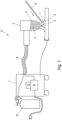
- Fig. 1 shows a schematic representation of a welding device 6 with a supply unit 7 and a welding head 3, which is connected to the supply unit 7 via a hose package 8.
- the supply unit 7 has at least one welding power source 9 and at least one protective gas source 10 in a manner known per se.
- the welding head 3 has a non-consumable electrode 2 and a protective gas nozzle 11.
- an arc 1 burns between the electrode 2 and a workpiece 5 and is ignited by the welding power source 9, regulated and maintained according to a set welding scheme.
- the welding power source 9 can be connected to a control and/or regulation unit 13.
- the protective gas flows through the protective gas nozzle 11, which surrounds the arc and protects the weld pool generated by the arc against unwanted influences from the ambient air.
- argon, helium and mixtures thereof, as well as argon with small amounts of nitrogen and oxygen can be used as protective gases.
- inert, reducing and oxidizing gas mixtures can also be used.
- the proportion of hydrogen in a gas mixture can be up to 5% by volume.
- the welding head 3 can also have a more complex structure.
- the welding head 3 can be designed as a plasma welding head, which can have a usually cooled plasma nozzle for constricting the arc. If necessary, this can also be done Protective gas supply and / or the protective gas composition can be regulated or controlled via the control and / or regulation unit 13.
- a welding filler 12 is advanced by hand or via an automated feed into the area heated by the arc, whereby the welding filler 12 melts and, together with the melted material of the workpiece 5, forms the melt pool, which forms the weld seam when hardening.
- the welding head 3 can be guided either by hand or automatically, for example by means of a welding robot.
- the welding filler can also be added either by hand or using an automatic welding wire feeder, the feed speed of which is coordinated with the movement of the welding head 3.
- the arc 1 Before each welding process, the arc 1 must be ignited without contact, as the non-melting electrode should not come into contact with the workpiece surface. If the non-melting electrode, which is usually a pure tungsten electrode or a tungsten electrode with oxidic additives, came into contact with the material surface, tungsten inclusions or tungsten residues would be found in the material surface or in the weld seam. Ignition is usually carried out using ignition voltage pulses that are applied by the welding power source 9 between the electrode 2 and the workpiece 5. The contactless ignition of the arc 1 is described in more detail below.
- the arc 1 is maintained according to a selected welding scheme, the welding scheme being, for example, the use of a constant current or constant power arc and a pulsed arc ( both represent DC welding processes) or alternating current arc (AC welding process).
- Fig. 2 to 4 show diagrams in which the course of the welding voltage U and the welding current I are compared before, during and after the ignition of the arc.
- Fig. 2 shows the arc igniting at the negative pole.
- the ignition process begins at time t1, with a sequence of negative ignition voltage pulses being applied between the electrode 2 and the workpiece 5 to ignite the arc.
- This type of ignition with negative ignition voltage pulses on the electrode is also referred to as “minus ignition”.
- the ignition process can be triggered, for example, by pressing a torch button (for manual welding) or by a machine control (for machine welding). In the case shown as an example, it ignites Arc only occurs after a considerable delay, namely with the seventh ignition voltage pulse (time t2).
- time t2 for example, if ignition voltage pulses each have a length of 5 ms and are applied at a frequency of 100 ignition voltage pulses per second, this corresponds to: Fig. 2 an ignition delay of 70 ms.
- the ignition delay is an indication that the ignition process is not optimal for the given welding task.
- the arc 1 typical for the welding process is formed at time t2 in the ionized area generated by the ignition voltage pulses between the electrode 2 and the workpiece 5, which can be seen in the current curve by a strong (negative) increase in the welding current I.
- the welding power source 9 detects the ignition of the arc based on the welding current curve and does not generate any further ignition voltage pulses, but rather regulates the further welding process according to the selected welding scheme, for example with a constant welding current or a constant power or, as in the case shown, with a variable welding current is applied in the form of welding pulses, generating a pulsed arc.
- the welding scheme can also be continued with alternating current (AC welding process), as this can be advantageous when welding aluminum and its alloys or magnesium and its alloys.
- a typically set AC frequency for TIG welding aluminum, magnesium and their alloys is 100 Hz.
- the electrons migrate from the electrode 2 into the workpiece, so that the heat is mainly generated in the workpiece, which is also desirable for the formation of the weld pool.
- the electrode 2 heats up less and is therefore protected from excessive wear.
- the disadvantage of negative ignition is that the arc often does not burn very stably at the start of welding and that there can be noticeable ignition delays with certain welding materials. Most users find an ignition delay of more than half a second to be annoying. If necessary, complete ignition misfires can also occur, in which case the arc does not ignite at all in an ignition voltage pulse sequence of a predetermined length.
- the length of the sequence of ignition voltage pulses can be predetermined for operational reasons, for example by safety regulations and standards or by the capacities of the welding power source 9.
- FIG. 3 shows an exemplary course of the welding voltage U and the welding current I with such an ignition process on the positive pole, which is also referred to as “Reversed Polarity Ignition” (RPI ignition).
- RPI ignition Reversed Polarity Ignition
- the ignition method shown begins at time t1 with a sequence of positive ignition voltage pulses, with an arc being ignited with the fourth ignition voltage pulse (at time t2), which can be recognized by the increase in the (positive) welding current.
- the welding voltage and the welding current are maintained with positive polarity for a short warm-up period (for example approximately 10 to 20 ms), after which the polarity is reversed to the negative pole.
- the warm-up period extends from the end of the ignition voltage pulse to time t3. It can happen that the arc goes out again when the polarity is reversed, which is... Fig. 3 is the case at time t3.
- Igniting with the tungsten electrode on the positive pole can improve ignition reliability and arc stability when welding starts. However, it may be that the arc cannot be reversed and goes out again. Since the electrons migrate from the workpiece to the electrode when the positive pole is ignited, the tip of the electrode heats up significantly, which accelerates its wear. If the polarity of the arc cannot be reversed, the tip of the electrode will still be heavily stressed by the igniting positive arcs.
- Ignition at the positive pole can be difficult, particularly on smooth, polished surfaces.
- misfiring can occur because the very smooth workpiece surfaces that occur impair the ignition behavior at the positive pole.
- the optimal selection of the ignition method depends on numerous factors Material properties and parameters, such as surface roughness, the chemical composition of the material, crystallography and the grain size and distribution, coating, etc. If the correct selection is complicated enough, in some cases it can also happen that the Circumstances change during welding, for example that a previously selected and optimally functioning ignition method suddenly no longer works, for example if welding is to be continued on a previously made seam.
- Fig. 4 the course of the welding voltage U and the welding current I is shown during an advantageous ignition process, which always ensures optimal ignition reliability regardless of the respective material properties and parameters.
- a sequence of ignition voltage pulses is generated, which includes ignition voltage pulses with the first polarity and ignition voltage pulses with the second polarity.
- a first, negative ignition voltage pulse is first applied at time t1. If an arc is ignited immediately, the procedure is continued Fig. 2 continued in the manner shown.
- the first ignition voltage pulse does not cause an arc
- the first ignition voltage pulse is immediately followed (possibly with a predetermined delay) by a second ignition voltage pulse with reversed, positive polarity, in which an arc ignites at time t2.
- the arc is then maintained again over a warm-up period and reversed at time t3. This is followed again by the conventional welding process according to the selected welding scheme.
- Fig. 4 The arc ignites with the second ignition voltage pulse. However, it may take longer for ignition to occur. In this case, the ignition process is continued by the previously defined sequence of positive and negative ignition voltage pulses until a successful ignition is achieved.
- the sequence corresponds to a defined sequence scheme, which defines the positive and negative ignition voltage pulses.
- a pulse welding process pulsed DC welding process
- welding voltage pulses ( Fig. 4 above) and welding current pulses ( Fig. 4 below) which are interrupted by intermediate welding phases.
- the welding voltage/welding current is reduced to a lower basic welding voltage/current.
- the basic welding voltage/current can also be zero in the intermediate welding phases.
- the welding voltage pulses ( Fig. 4 above) and welding current pulses ( Fig. 4 below) can occur with a frequency in the range of 0.1 Hz to 10 kHz.
- a pulsed DC welding process is shown, from time t3 a constant current welding process (unpulsed DC welding process), an AC welding process or even a combination of AC welding process and DC welding process, a so-called AC-DC mix -Welding process.
- An AC-DC mix welding process includes welding phases in which a, preferably pulsed, DC welding process is carried out and welding phases in which an AC welding process is carried out.
- An AC-DC mix welding process can therefore mean that a plurality of welding voltage pulses with a first polarity occur during the welding process (e.g. pulsed DC welding process component with a first polarity), whereupon the polarity of the welding voltage is reversed to another second polarity (AC -Welding process component) and in turn a plurality of welding voltage pulses occur with this other second polarity (pulsed DC welding process component with a second polarity), whereupon the polarity of the welding voltage is reversed again, etc.
- an AC-DC mix welding process can also mean that after the occurrence of a plurality of welding voltage pulses with a first polarity (e.g. pulsed DC welding process component with a first polarity), the welding voltage is reversed several times, first to a second polarity and then back to the first polarity, then if necessary back to the second polarity etc. (AC welding process component), and only after the polarity has been reversed several times is a plurality of welding voltage pulses of the same polarity with the then given polarity again carried out (e.g. pulsed DC welding process component) .
- the type of welding process can be selected depending on the welding task to be completed.
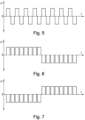
- sequence scheme refers to the definition of at least the polarities of the ignition voltage pulses that follow one another in a sequence. If necessary, the sequence scheme can also define other parameters, the other parameters being selected, for example from amplitudes of ignition voltage pulses, distances between two ignition voltage pulses and a maximum length of the sequence.
- Fig. 5 shows a sequence of ignition voltage pulses in which, starting with a positive ignition voltage pulse, a positive ignition voltage pulse is alternately carried out followed by a negative ignition voltage pulse. In an analogous way this can be done in Fig. 5 The sequence diagram shown also begins with a negative ignition voltage pulse.
- ignition pause means those time intervals in which the ignition voltage is at zero during the change from an ignition voltage pulse of a first polarity to an ignition voltage pulse of a second polarity (or vice versa).
- ignition pauses (occurring at a zero crossing) can be used to check whether an arc has already been ignited.
- Such ignition pauses should advantageously be kept short.
- ignition pauses have a duration between 50 ⁇ s and 0.1 ⁇ s; the duration for an ignition pause is preferably between 20 ⁇ s and 0.2 ⁇ s, particularly preferably between 10 ⁇ s and 0.5 ⁇ s.
- ignition pauses can be used to check whether an arc has already been ignited.
- Fig. 6 shows a further advantageous sequence scheme, in which a fixed number of positive ignition voltage pulses spaced apart by means of intermediate ignition phases is carried out, followed by a fixed number of negative ignition voltage pulses spaced apart by means of intermediate ignition phases. Since no polarity changes take place within a number of positive ignition voltage pulses or within a number of negative ignition voltage pulses, the distances between ignition voltage pulses of only one polarity, referred to as ignition phases, do not represent ignition pauses in the sense of the present invention.
- Fig. 6 shows an ignition pause according to the invention between two adjacent ignition voltage pulses of different polarity (middle of the diagram).
- Fig. 7 shows an analog sequence scheme that only differs in terms of polarity and begins with eight negative ignition voltage pulses spaced apart by intermediate ignition phases, followed by eight positive ignition voltage pulses spaced apart by intermediate ignition phases.
- Analogous to Fig. 6 also shows Fig. 7 an ignition pause according to the invention between two adjacent ignition voltage pulses of different polarity, the polarity change in comparison to Fig. 6 here takes place in the opposite direction.
- the intermediate ignition phases between the positive ignition voltage pulses can be of the same or different length as the intermediate ignition phases between the negative ignition voltage pulses.
- Such intermediate ignition phases can have a wide variety of durations, and can last, for example, a relatively long period of time between 50 ms and 5 ms, a relatively short period of time between 5 ms and 50 ⁇ s or a very short period of time between 50 ⁇ s and 0.1 ⁇ s.
- national or international standards and regulations can be taken into account in addition to the conditions for igniting the arc.
- the number of consecutive ignition voltage pulses of the same polarity in the sequence scheme can also be higher or lower than in Fig. 6 or 7 shown. If necessary, the number of consecutive ignition voltage pulses of the same polarity can also change within a sequence scheme or the number of consecutive ignition voltage pulses with positive polarity and those with negative polarity can differ from one another. If necessary, the total number of ignition voltage pulses with positive polarity may differ from the total number of ignition voltage pulses with negative polarity or they may be identical.
- the individual ignition voltage pulses point to the in Fig. 5 to 7
- the cases shown each have the same (positive or negative) amplitude and the same duration, and the time interval between two successive ignition voltage pulses is identical in each case.
- sequence schemes in which the ignition voltage pulses carried out one after the other can also differ in a defined manner with regard to these parameters.
- the average specialist is at Knowledge of the teachings disclosed herein will be able to sensibly select suitable sequence schemes through routine work and experiments, taking into account the additional conditions mentioned.
- the ignition voltage pulses are carried out according to the corresponding sequence scheme until either an arc is ignited or a maximum duration or maximum number of ignition voltage pulses defined for the sequence scheme is reached and the method terminates without ignition.
Description
Die gegenständliche Offenbarung betrifft eine Schweißvorrichtung und ein Verfahren zum berührungslosen Zünden eines Lichtbogens zwischen einer Elektrode eines Schweißkopfes und einer Materialoberfläche eines Werkstücks für einen Schweißprozess.The present disclosure relates to a welding device and a method for contactless ignition of an arc between an electrode of a welding head and a material surface of a workpiece for a welding process.
Konkret werden im Zuge der nachfolgenden Ausführungen DC-Schweißprozesse, bei denen während eines Schweißvorgangs eine Schweißspannung mit nur einer Polarität verwendet wird, und AC-Schweißprozesse, bei denen während eines Schweißvorgangs die Polarität der Schweißspannung wechselt, betrachtet.Specifically, the following explanations will consider DC welding processes in which a welding voltage with only one polarity is used during a welding process, and AC welding processes in which the polarity of the welding voltage changes during a welding process.
Sowohl bei DC-Schweißprozessen als auch bei AC-Schweißprozessen wird zu Beginn des Schweißprozesses im Rahmen eines Zündvorgangs ein Zündspannungsimpuls (Initialzündung) erzeugt, um den Lichtbogen initial zu erzeugen. Bei AC-Schweißprozesses werden überdies bei Wechsel der Polarität der Schweißspannung während des Schweißvorgangs, d.h. beim Nulldurchgang, Zündspannungsimpulse (Nulldurchgangszündung) erzeugt, um den Lichtbogen aufrecht zu erhalten, d.h. einen Abriss des Lichtbogens zu verhindern, was ebenso einem Zündvorgang entspricht.In both DC welding processes and AC welding processes, an ignition voltage pulse (initial ignition) is generated at the beginning of the welding process as part of an ignition process in order to initially generate the arc. In the AC welding process, when the polarity of the welding voltage changes during the welding process, i.e. at zero crossing, ignition voltage pulses (zero crossing ignition) are generated in order to maintain the arc, i.e. to prevent the arc from breaking off, which also corresponds to an ignition process.
Zum berührungslosen Zünden eines Lichtbogens zwischen einer Elektrode eines Schweißgeräts und einem Werkstück kann zwischen der Elektrode und dem Werkstück ein Zündspannungsimpuls, durch den der Bereich zwischen Elektrode und Werkstück ionisiert wird, angelegt werden, sodass der Lichtbogen im ionisierten Bereich zündet. Falls keine Zündung erfolgt (d.h. sich kein Lichtbogen bildet) wird nach einer kurzen Pause ein weiterer Zündspannungsimpuls mit gleicher Polarität angelegt. Sobald der Lichtbogen gezündet hat, wird eine Schweißspannung angelegt, mit der der Lichtbogen während des Schweißens aufrechterhalten wird.For non-contact ignition of an arc between an electrode of a welding machine and a workpiece, an ignition voltage pulse, through which the area between the electrode and the workpiece is ionized, can be applied between the electrode and the workpiece, so that the arc ignites in the ionized area. If ignition does not occur (i.e. no arc forms), another ignition voltage pulse with the same polarity is applied after a short pause. Once the arc has ignited, a welding voltage is applied to maintain the arc during welding.
Bei DC-Schweißprozessen (insbesondere zum Schweißen von Stahl und hochlegiertem Stahl) kann mit einem negativen Zündspannungsimpuls gestartet ("Zünden am Minuspol") werden, da auch das Schweißen mit einem negativen Schweißstrom erfolgt.DC welding processes (particularly for welding steel and high-alloy steel) can be started with a negative ignition voltage pulse ("ignition at the negative pole"), since welding also takes place with a negative welding current.
Einige modernere Schweißgeräte bieten auch die Möglichkeit, die Zündung mit einem positiven Zündspannungsimpuls zu starten ("Zünden am Pluspol"). Da das Schweißen üblicherweise mit einem negativen Schweißstrom erfolgen soll, erfolgt nach dem Zünden ein Umpolen. Bei einer Wolframelektrode kann das Zünden am Pluspol beispielsweise das Zündverhalten und die Lichtbogenstabilität beim Schweißstart verbessern. Ein Zünden am Pluspol führt zu einer erhöhten Belastung der Elektrode.Some more modern welding machines also offer the option of starting the ignition with a positive ignition voltage pulse ("ignition on the positive pole"). Since welding should usually be carried out with a negative welding current, the polarity is reversed after ignition. For example, with a tungsten electrode, ignition at the positive pole can improve ignition behavior and arc stability when welding starts. Ignition at the positive pole leads to increased load on the electrode.
Jedoch kann bei glatten, polierten Oberflächen die Zündung am Pluspol erschwert werden und es kann sein, dass der bereits gezündete Lichtbogen beim Umpolen erlischt bzw. dass der Lichtbogen generell nicht zündet.However, on smooth, polished surfaces, ignition at the positive pole can be made more difficult and it may be that the arc that has already been ignited goes out when the polarity is reversed or that the arc generally does not ignite.
In der Praxis muss der Anwender die gewünschte Zündeinstellung bzw. Zündpolarität auswählen und er muss diese umstellen, falls sich die gewählte Einstellung für die vorliegende Aufgabe nicht eignet, was sich durch häufige Zündaussetzer unangenehm bemerkbar macht. Dies kann sich auch auf die Qualität der Schweißnaht negativ auswirken. Das Auffinden der geeigneten Einstellung erfolgt dabei oft durch "Versuch und Irrtum", da dem Anwender meist nicht bewusst ist, warum (und wie genau) sich die beiden Zündmethoden voneinander unterscheiden, bzw. welche Parameter dabei wichtig sind und warum in einem gegebenen Fall das eine oder das andere Zündverfahren besser funktioniert. Auch kann es sein, dass sich Parameter während des Schweißens ändern, beispielsweise wenn am selben Werkstück über einer bereits hergestellten Schweißnaht geschweißt werden soll und diese Schweißnaht nun beispielsweise eine geringere Oberflächenrauigkeit aufweist, als das Werkstück und daher das gewählte Zündverfahren plötzlich weniger zuverlässig ist.In practice, the user has to select the desired ignition setting or ignition polarity and has to change this if the selected setting is not suitable for the task at hand, which is unpleasantly noticeable through frequent misfires. This can also have a negative impact on the quality of the weld seam. Finding the appropriate setting is often done through trial and error, as the user is usually not aware why (and how exactly) the two ignition methods differ from each other, or which parameters are important and why in a given case one or the other ignition method works better. It can also be the case that parameters change during welding, for example if welding is to be carried out on the same workpiece over a weld seam that has already been produced and this weld seam now, for example, has a lower surface roughness than the workpiece and therefore the selected ignition method is suddenly less reliable.
Die optimalen Zündeinstellungen bzw. die am besten geeignete Zündpolarität sind von zahlreichen Materialfaktoren abhängig, wie etwa der Oberflächenrauigkeit, der chemischen Zusammensetzung, kristallographischen Eigenschaften, Korngröße, Beschichtungen, etc. Insbesondere durch eine bereits vorhandene Schweißnaht oder eine andere z.B. lokale Temperaturbehandlung einer gegebenen Materialoberfläche können sich z.B. Korngrößen und kristallographische Eigenschaften und folglich das Zündverhalten ändern. Ferner können auch Seigerungen und Entmischungen einer z.B. erstarrten Schmelze (Schmelzgut) zu einem unterschiedlichen Zündverhalten führen. Auch ist bekannt, dass Poren, Einschlüsse, Lunker, Schlacke-Reste und andere Unregelmäßigkeiten der Oberfläche das Zündverhalten beeinflussen können. Ferner können auch durch Wärmebehandlung erzeugte Oxidschichten an der Oberfläche, aber auch eine vorhergehende Einbringung von beispielsweise Stickstoff oder Kohlenstoff in die Oberfläche, wie sie beispielsweise bei Oberflächenprozessen wie Nitrieren, Carbonitrieren, Plasmanitrieren etc. erzeugt werden, das Zündverhalten ändern. Ebenfalls führen z.B. lokale mechanische Oberflächenbehandlungen wie beispielsweise Fräsen, Schleifen, Polieren, Läppen, etc. bzw. mechanische Oberflächenbehandlungen im Allgemeinen zu einem geänderten Zündverhalten. Auch eventuell vorhandene Kontaminationen bzw. Kontaminationsschichten an der Oberfläche bzw. Rückstände von Reinigungsmitteln oder auch sich über die Zeit gebildete atmosphärenbedingte Absorptionssschichten oder aber auch eventuelle über die Zeit durch Atmosphäreneinfluss gebildete Reaktionschichten können einen Einfluss auf das Zündverhalten des Lichtbogens haben. Es ist daher auch für erfahrene Anwender nicht immer klar, welche Einstellungen und welche bevorzugte Polarität für eine vorliegende Aufgabe optimal sind. Ferner können Oberflächen, auch wenn visuell für den Schweißer nicht immer unbedingt sichtbar, ein derart inhomogenes Zündverhalten aufweisen, dass für jede Anwendung die Zündeinstellung individuell angepasst werden müsste.The optimal ignition settings or the most suitable ignition polarity depend on numerous material factors, such as surface roughness, chemical composition, crystallographic properties, grain size, coatings, etc. In particular, through an already existing weld seam or other, for example, local temperature treatment of a given material surface For example, grain sizes and crystallographic properties and consequently the ignition behavior change. Furthermore, segregation and separation of, for example, a solidified melt (molten material) can also lead to different ignition behavior. It is also known that pores, inclusions, voids, slag residues and other surface irregularities can influence the ignition behavior. Furthermore, oxide layers on the surface produced by heat treatment, but also a previous introduction of, for example, nitrogen or carbon into the surface, as are produced, for example, in surface processes such as nitriding, carbonitriding, plasma nitriding, etc., can change the ignition behavior. For example, local mechanical surface treatments such as milling, grinding, polishing, lapping, etc. or mechanical surface treatments in general lead to a changed ignition behavior. Any existing contamination or contamination layers on the surface or residues of cleaning agents or atmospheric absorption layers that have formed over time or possible reaction layers that have formed over time due to the influence of the atmosphere can also have an influence on the ignition behavior of the arc. It is therefore not always clear, even for experienced users, which settings and which preferred polarity is optimal for a given task. Furthermore, even if not always visually visible to the welder, surfaces can have such an inhomogeneous ignition behavior that the ignition setting would have to be adjusted individually for each application.
Auch aus dem Stand der Technik bekannte Ansätze zum Zünden von Lichtbögen, wie sie beispielsweise aus den Schriften
Es ist eine Aufgabe der gegenständlichen Offenbarung, Vorrichtungen und Verfahren bereitzustellen, mit denen die Zündsicherheit beim berührungslosen Zünden des Lichtbogens verbessert wird.It is an object of the present disclosure to provide devices and methods with which the ignition reliability is improved when the arc is ignited without contact.
Gemäß einem Aspekt betrifft die gegenständliche Offenbarung ein Verfahren zum berührungslosen Zünden eines Lichtbogens zwischen einer Elektrode eines Schweißkopfes und einer Materialoberfläche eines Werkstücks. Zwischen der Elektrode und der Materialoberfläche wird ein erster Zündspannungsimpuls mit einer ersten oder zweiten Polarität erzeugt, wobei der Lichtbogen nach dem Zünden und gegebenenfalls nach einem Umpolen mit der zweiten Polarität oder einer wechselnden Polarität aufrechterhalten wird, wobei im Falle eines Zündversagens nach dem ersten Zündspannungsimpuls bis zur erfolgreichen Zündung des Lichtbogens eine Abfolge an Zündspannungsimpulsen gemäß einem Abfolgeschema erzeugt wird, wobei das Abfolgeschema Zündspannungsimpulse mit der ersten Polarität und Zündspannungsimpulse mit der zweiten Polarität umfasst und wobei zwischen Zündspannungsimpulsen mit der ersten Polarität und der zweiten Polarität eine Zündpause vorgesehen ist. Dadurch kann die Zündung des Lichtbogens stets mit dem optimalen Zündverfahren erfolgen, ohne dass ein Bedienereingriff erforderlich ist. Zündaussetzer werden vermieden. Das Abfolgeschema ist vorzugsweise durch ein sich regelmäßig wiederholendes Muster an Zündspannungsimpulsen unterschiedlicher Polarität definiert.According to one aspect, the subject disclosure relates to a method for contactlessly igniting an arc between an electrode of a welding head and a material surface of a workpiece. A first ignition voltage pulse with a first or second polarity is generated between the electrode and the material surface, the arc being maintained with the second polarity or an alternating polarity after ignition and, if necessary, after a polarity reversal, in the event of an ignition failure after the first ignition voltage pulse until For successful ignition of the arc, a sequence of ignition voltage pulses is generated according to a sequence scheme, wherein the sequence scheme comprises ignition voltage pulses with the first polarity and ignition voltage pulses with the second polarity and wherein an ignition pause is provided between ignition voltage pulses with the first polarity and the second polarity. This means that the arc can always be ignited using the optimal ignition method without operator intervention being required. Misfires are avoided. The sequence scheme is preferably defined by a regularly repeating pattern of ignition voltage pulses of different polarities.
Eine Ausführungsform gemäß der gegenständlichen Offenbarung würde ebenso einschließen, dass der Betrag der Zündspannung bzw. des Zündstroms der ersten Polarität vom Betrag der Zündspannung bzw. des Zündstroms der zweiten Polarität abweicht. Eine weitere Ausführungsform gemäß der gegenständlichen Offenbarung würde ebenso einschließen, dass die Zeitdauer der Zündspannung bzw. des Zündstroms der ersten Polarität von der Zeitdauer der Zündspannung bzw. des Zündstroms der zweiten Polarität abweicht. Gegebenenfalls können auch aufeinanderfolgende Zündspannungsimpulse derselben Polarität sich hinsichtlich des Betrags und/oder der Länge voneinander unterscheiden.An embodiment according to the present disclosure would also include that the magnitude of the ignition voltage or current of the first polarity differs from the magnitude of the ignition voltage or current of the second polarity. A further embodiment according to the subject disclosure would also include that the duration of the ignition voltage or current of the first polarity differs from the duration of the ignition voltage or current of the second polarity. If necessary, successive ignition voltage pulses of the same polarity can also differ from one another in terms of magnitude and/or length.
Die Zündpause zwischen den Zündimpulsen kann systembedingt und/oder durch die Implementierung der Schweißvorrichtung bedingt und/oder eine vom Anwender geforderte Zündpause sein. Zwischen Zündimpulsen unterschiedlicher Polarität vorgesehene Zündpausen können hierbei genutzt werden, um zu überprüfen, ob bereits eine Zündung eines Lichtbogens stattgefunden hat.The ignition pause between the ignition pulses can be due to the system and/or the implementation of the welding device and/or an ignition pause required by the user. Between ignition pulses of different polarity provided Ignition pauses can be used to check whether an arc has already been ignited.
Das Verfahren zum berührungslosen Zünden eines Lichtbogens kann auch als Zündvorgang bezeichnet werden. Ein Schweißprozess umfasst Zündvorgänge, in welchen der Lichtbogen gezündet wird, Schweißvorgänge, in denen der Lichtbogen brennt, und Leerlaufphasen, in welchen kein Lichtbogen brennt und auch keiner gezündet wird. Bei AC-Schweißprozessen kann auch während des Schweißvorgangs, bei einem Nulldurchgang des Schweißstroms, ein Zündvorgang erfolgenThe process for igniting an arc without contact can also be referred to as the ignition process. A welding process includes ignition processes in which the arc is ignited, welding processes in which the arc burns, and idle phases in which no arc burns and none is ignited. In AC welding processes, an ignition process can also occur during the welding process when the welding current crosses zero
Der Begriff "Polarität" bezieht sich jeweils auf die Polung der Elektrode. Die erste Polarität kann entweder eine positive oder eine negative Polung der Elektrode sein, die zweite Polarität ist durch die im Vergleich zur ersten Polarität umgekehrte Polarität definiert. Die Wahl der Polarität ist insbesondere abhängig vom zu verschweißenden Material, wobei die meisten Materialien mit einer negativ gepolten Elektrode geschweißt werden. In dem Fall entspricht die zweite Polarität der negativen Polung. Es gibt jedoch auch Materialien, insbesondere Aluminium und dessen Legierungen, die sich am Minuspol nur bedingt schweißen lassen. In dem Fall muss entweder am Minuspol mit einem teuren Schutzgas wie beispielsweise Helium oder am Pluspol mit beispielsweise Argon oder einen Helium-Argon Gasgemisch oder mit Wechselstrom (AC-Schweißprozess) geschweißt werden.The term “polarity” refers to the polarity of the electrode. The first polarity can be either a positive or a negative polarity of the electrode, the second polarity is defined by the reverse polarity compared to the first polarity. The choice of polarity depends in particular on the material to be welded, with most materials being welded with a negatively polarized electrode. In this case, the second polarity corresponds to the negative polarity. However, there are also materials, especially aluminum and its alloys, that can only be welded to a limited extent on the negative pole. In this case, welding must be carried out either on the negative pole with an expensive protective gas such as helium or on the positive pole with, for example, argon or a helium-argon gas mixture or with alternating current (AC welding process).
In vorteilhafter Weise kann das Abfolgeschema durch eine abwechselnde Abfolge jeweils eines Zündspannungsimpulsen mit der ersten Polarität gefolgt von einem Zündspannungsimpuls mit der zweiten Polarität oder umgekehrt definiert sein. Eine solche Abfolge ist insbesondere dann optimal, wenn eine bevorzugte Zündpolarität nicht bekannt ist.Advantageously, the sequence scheme can be defined by an alternating sequence of an ignition voltage pulse with the first polarity followed by an ignition voltage pulse with the second polarity or vice versa. Such a sequence is particularly optimal when a preferred ignition polarity is not known.
In einer weiteren vorteilhaften Ausführungsform kann das Abfolgeschema durch eine erste fixe oder variable Anzahl an Zündspannungsimpulsen mit der ersten Polarität gefolgt von einer zweiten fixen oder variablen Anzahl an aufeinanderfolgenden Zündspannungsimpulsen mit der zweiten Polarität oder umgekehrt definiert sein. Dies kann beispielsweise dann vorteilhaft sein, wenn eine bevorzugte Polarität bekannt ist und zuerst mit dieser Polarität ein Zünden versucht werden soll. Erst wenn nach einigen Versuchen die Zündung nicht erfolgt ist, wird auf die andere Polarität gewechselt. Die erste und die zweite Anzahl können gleich sein oder sich unterscheiden. Die so definierte Abfolge wird bis zum Zünden des Lichtbogens oder bis zu einer vorgegebenen maximalen Länge wiederholt.In a further advantageous embodiment, the sequence scheme can be defined by a first fixed or variable number of ignition voltage pulses with the first polarity followed by a second fixed or variable number of successive ignition voltage pulses with the second polarity or vice versa. This can be advantageous, for example, if a preferred polarity is known and ignition should be attempted first with this polarity. Only if ignition fails after a few attempts will the switch be made to the other polarity. The first and second numbers may be the same or different. The sequence defined in this way is repeated until the arc is ignited or up to a predetermined maximum length.
Bei einem Zünden des Lichtbogens nach einem Zündspannungsimpuls mit der ersten Polarität kann der Lichtbogen vorzugsweise für einen Aufwärmzeitraum bei der ersten Polarität aufrechterhalten werden, wonach ein Umpolen auf die zweite Polarität erfolgt. Durch den Aufwärmzeitraum wird die Stabilität des Lichtbogens erhöht, was das Umpolen erleichtert.When the arc is ignited after an ignition voltage pulse with the first polarity, the arc can preferably be maintained at the first polarity for a warm-up period, after which the polarity is reversed to the second polarity. The warm-up period increases the stability of the arc, which makes reversing the polarity easier.
In vorteilhafter Weise kann bei einem Verlöschen des Lichtbogens während des Umpolens die zuvor begonnen Abfolge an Zündspannungsimpulsen gemäß dem Abfolgeschema fortgesetzt werden. Dies kann das Zündverhalten verbessern, wenn zwar der Lichtbogen beim Zündspannungsimpuls mit der ersten Polarität zündet, aber beim Umpolen wieder verlöscht. Alternativ kann die Abfolge an Zündspannungsimpulsen nach dem Verlöschen des Lichtbogens beim Umpolen gemäß demselben oder einem anderen Abfolgeschema neu begonnen werden.Advantageously, if the arc goes out during the polarity reversal, the previously started sequence of ignition voltage pulses can be continued according to the sequence scheme. This can improve the ignition behavior if the arc ignites with the ignition voltage pulse with the first polarity, but goes out again when the polarity is reversed. Alternatively, the sequence of ignition voltage pulses can be started again after the arc has been extinguished during polarity reversal according to the same or a different sequence scheme.
In vorteilhafter Weise kann zumindest eine Kenngröße, welche eine Qualität und/oder ein Zündverhalten des jeweils verwendeten Abfolgeschemas bewertet, ermittelt werden, wobei gegebenenfalls die ermittelte Kenngröße gespeichert und/oder über eine Benutzerschnittstelle bzw. über eine Ein- und Ausgabeeinheit dargestellt wird. Die Kenngröße kann eine beliebige gemessene oder abgeleitete Größe sein, welche eine Beurteilung der Qualität und/oder des Zündverhaltens erlaubt. Die Kenngröße kann beispielsweise eine Anzahl an erfolglosen Zündversuchen auf einem oder auf beiden Polaritäten repräsentieren. Gegebenenfalls kann die Kenngröße eine bestimmte Eigenschaft eines Abfolgeschemas und/oder eines Zündimpulses (insb. dessen Dauer und/oder Spannung), bei der eine Zündung erfolgreich oder unerfolgreich war, repräsentieren. Es können jedoch auch zahlreiche andere Mess- und/oder ermittelbare Werte als Kenngröße verwendet werden.Advantageously, at least one parameter, which evaluates a quality and/or an ignition behavior of the sequence scheme used in each case, can be determined, whereby the determined parameter is optionally stored and/or displayed via a user interface or via an input and output unit. The parameter can be any measured or derived variable that allows an assessment of the quality and/or the ignition behavior. The parameter can, for example, represent a number of unsuccessful ignition attempts on one or both polarities. If necessary, the parameter can represent a specific property of a sequence scheme and/or an ignition pulse (in particular its duration and/or voltage) at which an ignition was successful or unsuccessful. However, numerous other measurable and/or determinable values can also be used as a parameter.
In einer weiteren vorteilhaften Ausführungsform kann bei Unterschreitung oder Überschreitung oder Erreichen eines zuvor definierten Grenzwerts der Kenngröße automatisch ein alternatives Abfolgeschema ausgewählt werden. Dadurch kann das Verfahren automatisch verbessert werden, falls die Zündung in einem bestimmten Anwendungsfall nicht optimal funktionert.In a further advantageous embodiment, an alternative sequence scheme can be automatically selected when the parameter falls below or exceeds or reaches a previously defined limit value. This allows the process to be automatically improved if the ignition does not function optimally in a particular application.
In vorteilhafter Weise kann das alternative Abfolgeschema entweder zufällig aus mehreren Abfolgeschemen ausgewählt oder mit Hilfe eines gegebenenfalls lernfähigen Algorithmus generiert werden. Der lernfähige Algorithmus kann dabei Verfahren der künstlichen Intelligenz (z.B. unter Verwendung neuronaler Netze) oder eine "klassische" Programmierung, etwa auf Basis von Kennlinien oder Kennfeldern, verwenden. Dadurch lässt sich beispielsweise das Zündverhalten einer individuellen Schweißvorrichtung, die das gegenständliche Verfahren ausführt, automatisch optimal auf die vom Benutzer bevorzugten und/oder benötigten Umgebungs- und Schweißbedingungen anpassen. Gegebenenfalls kann der lernfähige Algorithmus auch jegliche verfügbaren Informationen über Umgebungsbedingungen und/oder Werkstoffparameter und/oder Schweißparameter zur Optimierung des Abfolgeschemas verwenden.Advantageously, the alternative sequence scheme can either be randomly selected from several sequence schemes or generated using an algorithm that may be capable of learning. The adaptive algorithm can use artificial intelligence methods (e.g. using neural networks) or “classic” programming, for example based on characteristic curves or maps. This allows, for example, the ignition behavior of an individual welding device that carries out the method in question to be automatically optimally adapted to the environmental and welding conditions preferred and/or required by the user. If necessary, the adaptive algorithm can also use any available information about environmental conditions and/or material parameters and/or welding parameters to optimize the sequencing scheme.
Der Schweißprozess kann ein AC-Schweißprozess sein. Das bedeutet, dass nach dem berührungslosen Zünden des Lichtbogens während des Schweißvorgangs ein Schweißstrom mit wechselnder Polarität fließt.The welding process can be an AC welding process. This means that after the arc has been ignited without contact during the welding process, a welding current with alternating polarity flows.
Der Schweißprozess kann aber auch ein DC-Schweißprozess sein. Das bedeutet, dass nach dem berührungslosen Zünden des Lichtbogens während des Schweißvorgangs ein Schweißstrom mit einer Polarität fließt, wobei der Schweißstrom auch gepulst sein kann.The welding process can also be a DC welding process. This means that after the arc has been ignited without contact during the welding process, a welding current with one polarity flows, whereby the welding current can also be pulsed.
Ist der Schweißprozess ein AC-Schweißprozess, so kann das berührungslose Zünden des Lichtbogens während des Schweißvorgangs erfolgen. Das bedeutet, dass das berührungslose Zünden bei Wechsel der Polarität, d.h. bei einem Nulldurchgang des Schweißstroms erfolgt, womit ein Abreißen des Lichtbogens verhindert wird.If the welding process is an AC welding process, the arc can be ignited without contact during the welding process. This means that contactless ignition occurs when the polarity changes, i.e. when the welding current crosses zero, which prevents the arc from breaking off.
Das berührungslose Zünden des Lichtbogens kann aber auch zu Beginn des Schweißprozesses erfolgen. Der Schweißvorgang wird somit durch einen Zündvorgang eingeleitet. Dies kann für AC-Schweißprozesse als auch für DC-Schweißprozesse Anwendung finden.The contactless ignition of the arc can also take place at the beginning of the welding process. The welding process is thus initiated by an ignition process. This can be used for AC welding processes as well as for DC welding processes.
Vorzugsweise werden im Abfolgeschema die Zündspannungsimpulse zumindest zweimal umgepolt. Das bedeutet, dass das Abfolgeschema entweder zumindest einen Zündspannungsimpuls mit einer ersten Polarität, gefolgt von zumindest einem Zündspannungsimpuls mit einer zweiten Polarität, gefolgt von zumindest einem Zündspannungsimpuls mit einer ersten Polarität umfasst oder zumindest einen Zündspannungsimpuls mit einer zweiten Polarität, gefolgt von zumindest einem Zündspannungsimpuls mit einer ersten Polarität, gefolgt von zumindest einem Zündspannungsimpuls mit einer zweiten Polarität umfasst. Vorzugsweise können in diesem Sinn auch mehr als zwei Polaritätsänderungen vorgenommen werden.Preferably, the ignition voltage pulses are reversed at least twice in the sequence scheme. This means that the sequence scheme comprises either at least one ignition voltage pulse with a first polarity, followed by at least one ignition voltage pulse with a second polarity, followed by at least one ignition voltage pulse with a first polarity, or at least one ignition voltage pulse with a second polarity, followed by at least one ignition voltage pulse a first polarity, followed by at least one ignition voltage pulse with a second polarity. In this sense, more than two polarity changes can preferably be carried out.
In einem weiteren Aspekt betrifft die gegenständliche Offenbarung eine Schweißvorrichtung mit einem Schweißkopf, an dem eine Elektrode vorgesehen ist, wobei die Elektrode mit einer Versorgungseinheit verbunden ist, mit welcher in geregelter Weise eine Spannung zwischen der Elektrode und einer Materialoberfläche eines Werkstücks anlegbar ist. Die Versorgungseinheit ist ausgebildet, zum berührungslosen Zünden eines Lichtbogens zwischen der Elektrode und der Materialoberfläche einen ersten Zündspannungsimpuls mit einer ersten oder zweiten Polarität zu erzeugen und den Lichtbogen nach dem Zünden und gegebenenfalls nach einem Umpolen mit der zweiten Polarität aufrechtzuerhalten, wobei die Versorgungseinheit weiters dazu ausgebildet ist, im Falle eines Zündversagens nach dem ersten Zündspannungsimpuls bis zur erfolgreichen Zündung des Lichtbogens eine Abfolge an Zündspannungsimpulsen gemäß einem Abfolgeschema zu erzeugen, wobei das Abfolgeschema Zündspannungsimpulse mit der ersten Polarität und Zündspannungsimpulse mit der zweiten Polarität umfasst. Die Schweißvorrichtung ist dadurch einfach zu handhaben und stellt bei unterschiedlichen Werkstoffen und Parametern ein zuverlässiges berührungsloses Zünden des Lichtbogens sicher.In a further aspect, the subject disclosure relates to a welding device with a welding head on which an electrode is provided, the electrode being connected to a supply unit with which a voltage can be applied in a controlled manner between the electrode and a material surface of a workpiece. The supply unit is designed to generate a first ignition voltage pulse with a first or second polarity for contactless ignition of an arc between the electrode and the material surface and to maintain the arc with the second polarity after ignition and, if necessary, after a polarity reversal, the supply unit being further designed for this purpose is to generate a sequence of ignition voltage pulses according to a sequence scheme in the event of an ignition failure after the first ignition voltage pulse until the arc has been successfully ignited, the sequence scheme comprising ignition voltage pulses with the first polarity and ignition voltage pulses with the second polarity. The welding device is therefore easy to handle and ensures reliable, non-contact ignition of the arc with different materials and parameters.
In vorteilhafter Weise kann in der Schweißvorrichtung, insbesondere in einer Steuerungs- und/oder Regelungseinheit der Schweißvorrichtung, eine interne Datenbank mit gespeicherten Abfolgeschemen für unterschiedliche Materialien und/oder Oberflächen gespeichert sein.An internal database with stored sequence schemes for different materials and/or surfaces can advantageously be stored in the welding device, in particular in a control and/or regulation unit of the welding device.
In vorteilhafter Weise kann die interne Datenbank mit einer externen Datenbank, in der Abfolgeschemen gespeichert sind, zumindest teilweise synchronisierbar sein, wobei die Schweißvorrichtung ausgebildet sein kann, zumindest zeitweise eine Verbindung mit einem externen Speicher und/oder einem Netzwerk und/oder einer Cloud, in denen die externe Datenbank gespeichert ist, aufzubauen. Dadurch lassen sich die mit der Schweißvorrichtung gewonnenen Erkenntnisse und entwickelten Verbesserungen auch für andere, gleichartige Schweißvorrichtungen nutzen und umgekehrt.Advantageously, the internal database can be at least partially synchronized with an external database in which sequence schemes are stored, wherein the welding device can be designed to at least temporarily be connected to an external memory and/or a network and/or a cloud in which the external database is stored. This means that the knowledge gained and improvements developed with the welding device can also be used for other, similar welding devices and vice versa.
In einer weiteren vorteilhaften Ausführungsform kann zumindest ein gespeichertes Abfolgeschema vom Anwender über eine Ein- oder Ausgabeeinheit programmierbar sein. Dies erlaubt insbesondere sehr erfahrenen und geschulten Benutzern eine spezifische Anpassung der Schweißvorrichtung an ihre eigenen Bedingungen.In a further advantageous embodiment, at least one stored sequence scheme can be programmable by the user via an input or output unit. This allows, in particular, very experienced and trained users to specifically adapt the welding device to their own conditions.
In vorteilhafter Weise kann ein aktuell ausgewähltes Abfolgeschema über eine Benutzerschnittstelle bzw. über eine Ein- und Ausgabeeinheit darstellbar sein. Die Darstellung kann beispielsweise anhand einer Bezeichnung des Abfolgeschemas oder mithilfe eines Piktogramms oder einer diagrammhaften Darstellung erfolgen. Dies erleichtert dem Benutzer das Erkennen des gewählten Abfolgeschemas und das Wiedererkennen eines zuvor erfolgreich eingesetzten Abfolgeschemas.Advantageously, a currently selected sequence scheme can be displayed via a user interface or via an input and output unit. The representation can be done, for example, using a name of the sequence scheme or using a pictogram or a diagrammatic representation. This makes it easier for the user to recognize the selected sequence scheme and to recognize a previously successfully used sequence scheme.
In vorteilhafter Weise kann zumindest eine Kenngröße, welche eine Qualität und/oder ein Zündverhalten des jeweils verwendeten Abfolgeschemas bewertet, ermittelbar sein, wobei die ermittelte Kenngröße gegebenenfalls gespeichert und/oder über eine Benutzerschnittstelle bzw. über eine Ein- und Ausgabeeinheit darstellbar sein kann. Diese Ermittlung und Verwaltung der Kenngröße(n) erleichtert die Implementierung von Qualitätssicherungs- und -steigerungsmechanismen. Gegebenenfalls können die Kenngrößen über die Synchronisierung mit anderen Erfahrungswerten abgeglichen und gegebenenfalls an den Hersteller übermittelt werden, was zur Umsetzung gezielter Produktverbesserungen genutzt werden kann.Advantageously, at least one parameter, which evaluates a quality and/or an ignition behavior of the sequence scheme used in each case, can be determined, the determined parameter possibly being stored and/or displayable via a user interface or via an input and output unit. This determination and management of the parameter(s) facilitates the implementation of quality assurance and improvement mechanisms. If necessary, the parameters can be compared with other empirical values via synchronization and, if necessary, transmitted to the manufacturer, which can be used to implement targeted product improvements.
In einer weiteren bevorzugten Ausführungsform kann die Schweißvorrichtung ausgebildet sein, einen lernfähigen Algorithmus anzuwenden und ein für eine optimale Zündung geeignetes Abfolgeschema automatisch auszuwählen und anzupassen. Dadurch "lernt" die Schweißvorrichtung auf Basis der im Einsatz gemachten "Erfahrungen" und Erkenntnisse.In a further preferred embodiment, the welding device can be designed to use an adaptive algorithm and to automatically select and adapt a sequence scheme suitable for optimal ignition. As a result, the welding device “learns” based on the “experience” and knowledge gained during use.
Durch den lernfähigen Algorithmus können Fehlerquellen erkannt und deren Lösungsansätze automatisiert umgesetzt werden.The adaptive algorithm allows sources of errors to be identified and possible solutions to be implemented automatically.
Die gegenständliche Erfindung wird nachfolgend unter Bezugnahme auf die
-
Fig. 1 eine blockhafte schematische Darstellung einer Schweißvorrichtung, -
Fig. 2 ein Diagramm beispielhafter Spannungs- und Stromverläufe bei Zünden eines Lichtbogens am Minuspol, -
Fig. 3 ein Diagramm beispielhafter Spannungs- und Stromverläufe bei Zünden eines Lichtbogens am Pluspol, -
Fig. 4 ein Diagramm beispielhafter Spannungs- und Stromverläufe beim Zünden eines Lichtbogens mit einer Abfolge an Zündspannungsimpulsen beginnend mit einem negativen Impuls und -
Fig. 5 bis Fig. 7 Diagramme von Abfolgen an Zündspannungsimpulsen gemäß unterschiedlicher Abfolgeschemata.
-
Fig. 1 a blocky schematic representation of a welding device, -
Fig. 2 a diagram of exemplary voltage and current curves when an arc is ignited at the negative pole, -
Fig. 3 a diagram of exemplary voltage and current curves when an arc is ignited at the positive pole, -
Fig. 4 a diagram of exemplary voltage and current curves when igniting an arc with a sequence of ignition voltage pulses starting with a negative pulse and -
Fig. 5 to Fig. 7 Diagrams of sequences of ignition voltage pulses according to different sequence schemes.
Der Schweißkopf 3 weist eine nicht abschmelzende Elektrode 2 und eine Schutzgasdüse 11 auf. Zwischen der Elektrode 2 und einem Werkstück 5 brennt während des Schweißens ein Lichtbogen 1, welcher von der Schweißstromquelle 9 gezündet, geregelt und gemäß einem eingestellten Schweißschema aufrechterhalten wird. Zur Steuerung und Regelung kann die Schweißstromquelle 9 mit einer Steuerungs- und/oder Regelungseinheit 13 in Verbindung stehen. Über die Schutzgasdüse 11 strömt während des Schweißens das Schutzgas, welches den Lichtbogen umgibt und das vom Lichtbogen erzeugte Schweißbad gegen unerwünschte Einflüsse der Umgebungsluft schützt. Als Schutzgase können beispielsweise Argon, Helium und Gemische daraus, sowie Argon mit geringen Anteilen von Stickstoff und Sauerstoff verwendet werden. Ferner können ebenso reaktionsträge, reduzierende und oxidierende Gasgemische verwendet werden. Beispielsweise kann der Anteil von Wasserstoff in einem Gasgemisch bis zu 5 Vol. % betragen. Gegebenenfalls kann der Schweißkopf 3 auch komplexer aufgebaut sein. Beispielsweise kann der Schweißkopf 3 als Plasmaschweißkopf ausgebildet sein, der eine üblicherweise gekühlte Plasmadüse zur Einschnürung des Lichtbogens aufweisen kann. Gegebenenfalls kann auch die Schutzgaszufuhr und/oder die Schutzgaszusammensetzung über die Steuerungs- und/oder Regelungseinheit 13 geregelt bzw. gesteuert werden.The
Während des Schweißens wird von Hand oder über eine automatisierte Zuführung ein Schweißzusatz 12 in den vom Lichtbogen erwärmten Bereich vorgeschoben, wobei der Schweißzusatz 12 abschmilzt und zusammen mit dem aufgeschmolzenen Material des Werkstücks 5 das Schmelzbad ausbildet, welches beim Erhärten die Schweißnaht bildet. Der Schweißkopf 3 kann entweder von Hand oder automatisch, beispielsweise mittels eines Schweißroboters, geführt werden. Auch der Schweißzusatz kann entweder von Hand hinzugefügt werden, oder mithilfe einer automatischen Schweißdrahtzuführung, deren Vorschubgeschwindigkeit auf die Bewegung des Schweißkopfes 3 abgestimmt ist.During welding, a
Vor jedem Schweißvorgang muss der Lichtbogen 1 berührungslos gezündet werden, da die nicht abschmelzende Elektrode nicht mit der Werkstückoberfläche in Kontakt gelangen soll. Würde die nicht abschmelzende Elektrode, wobei es sich in der Regel um eine reine Wolframelektrode oder eine mit oxidischen Zusätzen versehene Wolframelektrode handelt, mit der Werkstoffoberfläche in Kontakt kommen, so würden sich Wolframeinschlüsse oder Wolfram rückstände in der Werkstoffoberfläche bzw. in der Schweißnaht wiederfinden. Die Zündung erfolgt üblicherweise mithilfe von Zündspannungsimpulsen, die von der Schweißstromquelle 9 zwischen der Elektrode 2 und dem Werkstück 5 angelegt werden. Das berührungslose Zünden des Lichtbogens 1 wird hierin weiter unten noch eingehend beschrieben.Before each welding process, the arc 1 must be ignited without contact, as the non-melting electrode should not come into contact with the workpiece surface. If the non-melting electrode, which is usually a pure tungsten electrode or a tungsten electrode with oxidic additives, came into contact with the material surface, tungsten inclusions or tungsten residues would be found in the material surface or in the weld seam. Ignition is usually carried out using ignition voltage pulses that are applied by the
Sobald der Lichtbogen 1 stabil brennt, (was von der Schweißstromquelle 9 durch einen Anstieg des Schweißstroms erkannt wird), wird der Lichtbogen 1 gemäß einem gewählten Schweißschema aufrechterhalten, wobei das Schweißschema beispielsweise die Verwendung eines Lichtbogens mit konstantem Strom oder konstanter Leistung sowie eines Impulslichtbogens (beides stellen DC-Schweißprozesse dar) oder Wechselstromlichtbogens (AC-Schweißprozess) vorgeben kann.Once the arc 1 is burning stably (which is detected by the
Beim siebenten Zündspannungsimpuls bildet sich zum Zeitpunkt t2 in dem durch die Zündspannungsimpulse zwischen der Elektrode 2 und dem Werkstück 5 erzeugen ionisierten Bereich der für den Schweißprozess typische Lichtbogen 1 aus, was im Stromverlauf durch einen starken (negativen) Anstieg des Schweißstroms I erkennbar ist.At the seventh ignition voltage pulse, the arc 1 typical for the welding process is formed at time t2 in the ionized area generated by the ignition voltage pulses between the
Die Schweißstromquelle 9 erkennt anhand des Schweißstromverlaufs das Zünden des Lichtbogens und erzeugt keine weiteren Zündspannungsimpulse, sondern regelt den weiteren Schweißprozess gemäß dem gewählten Schweißschema, also beispielsweise mit einem konstanten Schweißstrom oder einer konstanten Leistung oder, wie im dargestellten Fall, mit einem veränderlichen Schweißstrom, der in Form von Schweißimpulsen aufgebracht wird, wobei ein Impulslichtbogen erzeugt wird. Gegebenenfalls kann das Schweißschema auch mit Wechselstrom (AC-Schweißprozess) fortgeführt werden, wie dies etwa bei Schweißen von Aluminium und dessen Legierungen oder auch von Magnesium und dessen Legierungen vorteilhaft sein kann. Eine typisch eingestellte Wechselstrom-Frequenz für das WIG-Schweißen von Aluminium, Magnesium und deren Legierungen beträgt 100 Hz.The
Beim Zünden des Lichtbogens am negativen Pol (also bei einer Minuszündung) wandern die Elektronen von der Elektrode 2 in das Werkstück, sodass die Wärme hauptsächlich im Werkstück erzeugt wird, was zur Bildung des Schweißbades auch erwünscht ist. Die Elektrode 2 erwärmt sich weniger stark und wird dadurch vor übermäßiger Abnutzung geschützt. Nachteilig ist bei der Minuszündung, dass der Lichtbogen am Schweißbeginn oft noch nicht sehr stabil brennt und dass es bei bestimmten Schweißmaterialien zu merkbaren Zündverzögerungen kommen kann. Eine Zündverzögerung von mehr als einer halben Sekunde wird von den meisten Benutzern bereits als störend empfunden. Gegebenenfalls kann es auch zu vollständigen Zündaussetzern kommen, wobei dann der Lichtbogen in einer Zündspannungsimpuls-Abfolge vorgegebener Länge gar nicht zündet. Die Länge der Abfolge an Zündspannungsimpulsen kann beispielsweise durch Sicherheitsvorschriften und Normen oder durch die Kapazitäten der Schweißstromquelle 9 betriebsbedingt vorgegeben sein.When the arc is ignited at the negative pole (i.e. with a negative ignition), the electrons migrate from the
Um die Zuverlässigkeit der Zündung und die Stabilität des Lichtbogens nach dem Zünden zu erhöhen, wurde ein alternatives Zündverfahren entwickelt, bei dem die Zündung am Pluspol erfolgt. Da der Schweißvorgang selbst meist mit negativer Polung ausgeführt wird, muss der Lichtbogen für das Schweißen üblicherweise noch auf den Minuspol umgepolt werden, sobald er stabil brennt.
Das in
Wird mit der Wolframelektrode auf dem Pluspol gezündet, kann dies die Zuverlässigkeit der Zündung und die Lichtbogenstabilität beim Schweißstart verbessern. Allerdings kann es sein, dass sich der Lichtbogen nicht umpolen lässt und dabei wieder verlöscht. Da bei der Zündung am Pluspol die Elektronen vom Werkstück zur Elektrode wandern, erwärmt sich die Elektrodenspitzt stark, was deren Abnutzung beschleunigt. Wenn sich der Lichtbogen nicht umpolen lässt, wird dennoch die Elektrodenspitze durch die zündenden positiven Lichtbögen stark beansprucht.Igniting with the tungsten electrode on the positive pole can improve ignition reliability and arc stability when welding starts. However, it may be that the arc cannot be reversed and goes out again. Since the electrons migrate from the workpiece to the electrode when the positive pole is ignited, the tip of the electrode heats up significantly, which accelerates its wear. If the polarity of the arc cannot be reversed, the tip of the electrode will still be heavily stressed by the igniting positive arcs.
Insbesondere bei glatten, polierten Oberflächen kann die Zündung am Pluspol erschwert werden. Beispielsweise können etwa beim Schweißen von Hoch- und Niedriglegierten Stählen, sowie Nichteisenmetallen oder bei Wiederzündungen am selben Schweißpunkt bzw. bei überlappenden Schweißpunkten am Pluspol Zündaussetzer auftreten, da die dabei auftretenden sehr glatten Werkstückoberflächen das Zündverhalten am Pluspol verschlechtern. Die optimale Auswahl des Zündverfahrens hängt dabei von zahlreichen Werkstoffeigenschaften und Parametern ab, wie etwa der Oberflächenrauigkeit, der chemischen Zusammensetzung des Materials, der Kristallographie und der Korngröße und - verteilung, Beschichtung, etc. Ist die richtige Auswahl schon kompliziert genug, so kann es in manchen Fällen auch dazu kommen, dass sich die Umstände während des Schweißens ändern, etwa dass ein zuvor gewähltes und optimal funktionierendes Zündverfahren plötzlich nicht mehr funktioniert, etwa wenn eine Schweißung an einer zuvor angefertigten Naht fortgesetzt werden soll.Ignition at the positive pole can be difficult, particularly on smooth, polished surfaces. For example, when welding high- and low-alloy steels, as well as non-ferrous metals, or when re-igniting at the same welding point or with overlapping welding points on the positive pole, misfiring can occur because the very smooth workpiece surfaces that occur impair the ignition behavior at the positive pole. The optimal selection of the ignition method depends on numerous factors Material properties and parameters, such as surface roughness, the chemical composition of the material, crystallography and the grain size and distribution, coating, etc. If the correct selection is complicated enough, in some cases it can also happen that the Circumstances change during welding, for example that a previously selected and optimally functioning ignition method suddenly no longer works, for example if welding is to be continued on a previously made seam.
In
In
Nach dem Zeitpunkt t3 zeigt
Die Grundschweißspannung/der Grundschweißstrom kann in den Schweißzwischenphasen auch null sein. Die Schweißspannungsimpulse (
Obwohl in
Ein AC-DC-Mix-Schweißprozess umfasst Schweißphasen, in denen ein, vorzugsweise gepulster, DC- Schweißprozess durchgeführt wird und Schweißphasen, in denen ein AC-Schweißprozess durchgeführt wird. Ein AC-DC-Mix-Schweißprozess kann demnach bedeuten, dass während des Schweißprozesses eine Mehrzahl an Schweißspannungsimpulsen mit einer ersten Polarität auftreten (z.B. gepulster DC-Schweißprozessanteil mit einer ersten Polarität), woraufhin eine Umpolung der Schweißspannung auf eine andere zweite Polarität erfolgt (AC-Schweißprozessanteil) und wiederum eine Mehrzahl an Schweißspannungsimpulsen mit dieser anderen zweiten Polarität auftreten (gepulster DC-Schweißprozessanteil mit einer zweiten Polarität), daraufhin wieder eine Umpolung der Schweißspannung erfolgt etc.An AC-DC mix welding process includes welding phases in which a, preferably pulsed, DC welding process is carried out and welding phases in which an AC welding process is carried out. An AC-DC mix welding process can therefore mean that a plurality of welding voltage pulses with a first polarity occur during the welding process (e.g. pulsed DC welding process component with a first polarity), whereupon the polarity of the welding voltage is reversed to another second polarity (AC -Welding process component) and in turn a plurality of welding voltage pulses occur with this other second polarity (pulsed DC welding process component with a second polarity), whereupon the polarity of the welding voltage is reversed again, etc.
Ein AC-DC-Mix-Schweißprozess kann aber auch bedeuten, dass nach einem Auftreten einer Mehrzahl an Schweißspannungsimpulsen mit einer ersten Polarität (z.B. gepulster DC-Schweißprozessanteil mit einer ersten Polarität) eine mehrfache Umpolung der Schweißspannung erfolgt, zunächst auf eine zweite Polarität, danach zurück auf die erste Polarität, danach gegebenenfalls wieder zurück auf die zweite Polarität usw. (AC-Schweißprozessanteil), und erst nach einer mehrfachen Umpolung der Polarität erneut eine Mehrzahl von Schweißspannungsimpulsen gleicher Polarität mit der dann gegebenen Polarität erfolgt (z.B. gepulster DC-Schweißprozessanteil). Die Auswahl der Art des Schweißprozesses kann dabei je nach zu erledigender Schweißaufgabe erfolgen.However, an AC-DC mix welding process can also mean that after the occurrence of a plurality of welding voltage pulses with a first polarity (e.g. pulsed DC welding process component with a first polarity), the welding voltage is reversed several times, first to a second polarity and then back to the first polarity, then if necessary back to the second polarity etc. (AC welding process component), and only after the polarity has been reversed several times is a plurality of welding voltage pulses of the same polarity with the then given polarity again carried out (e.g. pulsed DC welding process component) . The type of welding process can be selected depending on the welding task to be completed.
Wenn bei diesem Verfahren ein am positiven Pol gezündeter Lichtbogen während des Umpolens wieder erlischt, kann entweder die bereits begonnene, definierte Abfolge an Zündspannungsimpulsen mit dem im Abfolgeschema als nächstes vorgesehenen Zündspannungsimpuls fortgesetzt werden, oder die Abfolge kann nach demselben oder einem geänderten Abfolgeschema neu begonnen werden.If, with this method, an arc ignited at the positive pole goes out again during the polarity reversal, either the defined sequence of ignition voltage pulses that has already begun can be continued with the ignition voltage pulse provided next in the sequence scheme, or the sequence can be started again according to the same or a changed sequence scheme .
Als "Abfolgeschema" wird im Zusammenhang mit der gegenständlichen Offenbarung die Definition zumindest der Polaritäten der in einer Abfolge aufeinanderfolgenden Zündspannungsimpulse bezeichnet. Gegebenenfalls kann das Abfolgeschema auch andere Parameter definieren, wobei die anderen Parameter beispielsweise ausgewählt sein können aus Amplituden von Zündspannungsimpulsen, Abständen zwischen jeweils zwei Zündspannungsimpulsen und einer maximalen Länge der Abfolge.In connection with the present disclosure, the “sequence scheme” refers to the definition of at least the polarities of the ignition voltage pulses that follow one another in a sequence. If necessary, the sequence scheme can also define other parameters, the other parameters being selected, for example from amplitudes of ignition voltage pulses, distances between two ignition voltage pulses and a maximum length of the sequence.
In
Zwischen zwei aufeinanderfolgenden Zündspannungsimpulsen unterschiedlicher Polarität zeigt
Da die Zündpausen wie erwähnt sehr kurz sein können, ist in
Wie erwähnt können (bei einem Nulldurchgang auftretende) Zündpausen genutzt werden, um zu überprüfen, ob bereits eine Zündung eines Lichtbogens stattgefunden hat.As mentioned, ignition pauses (occurring at a zero crossing) can be used to check whether an arc has already been ignited.
Im in
Die Zündzwischenphasen zwischen den positiven Zündspannungsimpulsen können gleicher oder unterschiedlicher Länge wie die Zündzwischenphasen zwischen den negativen Zündspannungsimpulsen sein. Derartige Zündzwischenphasen können unterschiedlichste Zeitdauern aufweisen, und beispielsweise eine relativ lange Zeitdauer zwischen 50 ms und 5 ms, eine relativ kurze Zeitdauer zwischen 5 ms und 50 µs oder eine sehr kurze Zeitdauer zwischen 50 µs und 0,1 µs dauern. Bei der Wahl dieser Zeitdauern können neben Bedingungen für die Zündung des Lichtbogens auch nationale oder internationale Normen und Vorschriften berücksichtigt werden.The intermediate ignition phases between the positive ignition voltage pulses can be of the same or different length as the intermediate ignition phases between the negative ignition voltage pulses. Such intermediate ignition phases can have a wide variety of durations, and can last, for example, a relatively long period of time between 50 ms and 5 ms, a relatively short period of time between 5 ms and 50 µs or a very short period of time between 50 µs and 0.1 µs. When choosing these time periods, national or international standards and regulations can be taken into account in addition to the conditions for igniting the arc.
Die Anzahl der im Abfolgeschema jeweils aufeinanderfolgenden Zündspannungsimpulse gleicher Polarität kann auch höher oder niedriger sein als in
Die einzelnen Zündspannungsimpulse weisen in den in
In allen Fällen werden die Zündspannungsimpulse gemäß dem entsprechenden Abfolgeschema solange ausgeführt, bis entweder ein Lichtbogen zündet oder eine für das Abfolgeschema definierte Maximaldauer oder maximale Zündspannungsimpulsanzahl erreicht ist und das Verfahren ohne Zündung abbricht.In all cases, the ignition voltage pulses are carried out according to the corresponding sequence scheme until either an arc is ignited or a maximum duration or maximum number of ignition voltage pulses defined for the sequence scheme is reached and the method terminates without ignition.
Die in den einzelnen Ausgestaltungen und Beispielen angegebenen einzelnen Merkmale und Varianten können (sofern nicht an Ort und Stelle etwas anderes ausgeführt ist) mit denen der anderen Beispiele und Ausgestaltungen frei kombiniert und insbesondere zur Kennzeichnung der Erfindung in den Ansprüchen ohne zwangläufige Mitnahme der anderen Details der jeweiligen Ausgestaltung bzw. des jeweiligen Beispiels verwendet werden.The individual features and variants specified in the individual embodiments and examples can (unless otherwise stated on site) be freely combined with those of the other examples and embodiments and in particular to characterize the invention in the claims without necessarily including the other details of the respective embodiment or the respective example can be used.
- Lichtbogen 1Arc 1
-
Elektrode 2
Electrode 2 -
Schweißkopf 3
Welding head 3 - Materialoberfläche 4Material surface 4
-
Werkstück 5
Workpiece 5 -
Schweißvorrichtung 6
Welding device 6 -
Versorgungseinheit 7
Supply unit 7 -
Schlauchpaket 8
Hose package 8 -
Schweißstromquelle 9
Welding power source 9 - Schutzgasquelle 10Protective gas source 10
-
Schutzgasdüse 11
Protective gas nozzle 11 -
Schweißzusatz 12Welding
filler metal 12 -
Steuerungs- und/oder Regelungseinheit 13Control and/or
regulation unit 13
Claims (15)
- Method for contactlessly striking an arc (1) between an electrode (2) of a welding head (3) and a material surface (4) of a workpiece (5) for a welding process, characterized in that a first ignition voltage pulse with a first or second polarity is generated between the electrode (2) and the material surface (4), wherein, after having been struck and, where applicable, after a polarity reversal, the arc (1) is maintained with the second polarity or with an alternating polarity, wherein, in the event of an ignition failure, after the first ignition voltage pulse, a sequence of ignition voltage pulses is generated according to a sequence pattern until successful striking of the arc (1), wherein the sequence pattern comprises a number of ignition voltage pulses with the first polarity and a number of ignition voltage pulses with the second polarity, and wherein an ignition pause is provided between ignition voltage pulses with the first polarity and ignition voltage pulses with the second polarity.
- Method according to claim 1, characterized in that the sequence pattern is defined by an alternating sequence of an ignition voltage pulse with the first polarity followed by an ignition voltage pulse with the second polarity, or vice versa, or in that the sequence pattern is defined by a first fixed or variable number of ignition voltage pulses with the first polarity followed by a second fixed or variable number of successive ignition voltage pulses with the second polarity, or vice versa.
- Method according to one of claims 1 through 2, characterized in that, when the arc (1) is struck following an ignition voltage pulse with the first polarity, the arc is maintained for a warm-up period with the first polarity, after which the polarity is reversed to the second polarity.
- Method according to claim 3, characterized in that, if the arc is extinguished during the polarity reversal, the previously started sequence of ignition voltage pulses is continued in accordance with the sequence pattern.
- Method according to one of claims 1 through 4, characterized in that at least one parameter that evaluates a quality and/or an ignition behavior of the sequence pattern used is determined, wherein, where applicable, the determined parameter is stored and/or is displayed via a user interface or via an input and output unit.
- Method according to claim 5, characterized in that, if the parameter falls below or exceeds or reaches a previously defined limit value, an alternative sequence pattern is automatically selected.
- Method according to claim 6, characterized in that the alternative sequence pattern is either randomly selected from several sequence patterns or is generated with the aid of an optionally adaptive algorithm.
- Method according to one of claims 1 through 7, characterized in that the welding process is a DC welding process, at which the contactless striking of the arc occurs during the welding process, or in that the welding process is an AC welding process or a DC welding process, at which the contactless striking of the arc occurs at the start of the welding process.
- Method according to one of claims 1 through 8, characterized in that, in the sequence pattern, the ignition voltage pulses undergo a polarity reversal twice.
- Welding device (6) with a welding head (3), on which there is provided an electrode (2), wherein the electrode (2) is connected to a supply unit (7) by which a voltage (U) can be applied in controlled fashion between the electrode (2) and a material surface (4) of a workpiece (5), characterized in that the supply unit (7) is configured, for contactless striking of an arc (1) between the electrode (2) and the material surface (4), to produce a first ignition voltage pulse with a first or second polarity and to maintain the arc (1) with the second polarity after having been struck and, where applicable, after a polarity reversal, wherein the supply unit (7) is further configured, in the event of an ignition failure, after the first ignition voltage pulse until successful striking of the arc (1), to generate a sequence of ignition voltage pulses according to a sequence pattern, wherein the sequence pattern comprises a number of ignition voltage pulses with the first polarity and a number of ignition voltage pulses with the second polarity, and wherein an ignition pause is provided between ignition voltage pulses with the first polarity and ignition voltage pulses with the second polarity.
- Welding device according to claim 10, characterized in that an internal database containing stored sequence patterns for different materials and/or surfaces is stored in the welding device, in particular in an open-loop and/or closed-loop control unit (13) of the welding device.
- Welding device according to claim 11, characterized in that the internal database is at least partially synchronizable with an external database in which sequence patterns are stored, wherein the welding device is configured to establish at least temporarily a connection to an external memory and/or a network and/or a cloud in which the external database is stored.
- Welding device according to one of claims 10 through 12, characterized in that at least one stored sequence pattern is programmable by a user via an input or output unit and/or in that a currently selected sequence pattern can be displayed via a user interface or via an input and output unit.
- Welding device according to one of claims 10 through 13, characterized in that at least one parameter that evaluates a quality and/or an ignition behavior of the sequence pattern used can be determined, wherein the determined parameter, where applicable, is stored and/or can be displayed via a user interface or via an input and output unit.
- Welding device according to one of claims 10 through 14, characterized in that the welding device is configured to apply an adaptive algorithm and to automatically select and adapt a sequence pattern suitable for optimal striking.
Applications Claiming Priority (2)
| Application Number | Priority Date | Filing Date | Title |
|---|---|---|---|
| EP20190851 | 2020-08-13 | ||
| PCT/EP2021/072371 WO2022034132A1 (en) | 2020-08-13 | 2021-08-11 | Method and welding device for contactlessly striking an arc |
Publications (2)
| Publication Number | Publication Date |
|---|---|
| EP4196308A1 EP4196308A1 (en) | 2023-06-21 |
| EP4196308B1 true EP4196308B1 (en) | 2024-03-20 |
Family
ID=72086718
Family Applications (1)
| Application Number | Title | Priority Date | Filing Date |
|---|---|---|---|
| EP21758681.7A Active EP4196308B1 (en) | 2020-08-13 | 2021-08-11 | Method of and device for contactless ignition of an arc |
Country Status (6)
| Country | Link |
|---|---|
| US (1) | US20230347439A1 (en) |
| EP (1) | EP4196308B1 (en) |
| JP (1) | JP2023537594A (en) |
| CN (1) | CN116075383A (en) |
| MX (1) | MX2023001778A (en) |
| WO (1) | WO2022034132A1 (en) |
Family Cites Families (3)
| Publication number | Priority date | Publication date | Assignee | Title |
|---|---|---|---|---|
| DE1615363C3 (en) * | 1967-07-04 | 1974-11-07 | Messer Griesheim Gmbh, 6000 Frankfurt | Device for stabilizing and igniting welding arcs using current pulses |
| CA2139715A1 (en) * | 1994-02-10 | 1995-08-11 | Richard M. Hutchison | Synchronized pulse arc starter and stabilizer for arc welding |
| JPH10328827A (en) * | 1997-05-29 | 1998-12-15 | Mitsubishi Heavy Ind Ltd | Arc welding device and welding equipment |
-
2021
- 2021-08-11 CN CN202180056119.9A patent/CN116075383A/en active Pending
- 2021-08-11 US US18/020,719 patent/US20230347439A1/en active Pending
- 2021-08-11 MX MX2023001778A patent/MX2023001778A/en unknown
- 2021-08-11 JP JP2023509372A patent/JP2023537594A/en active Pending
- 2021-08-11 EP EP21758681.7A patent/EP4196308B1/en active Active
- 2021-08-11 WO PCT/EP2021/072371 patent/WO2022034132A1/en unknown
Also Published As
| Publication number | Publication date |
|---|---|
| EP4196308A1 (en) | 2023-06-21 |
| MX2023001778A (en) | 2023-03-10 |
| US20230347439A1 (en) | 2023-11-02 |
| CN116075383A (en) | 2023-05-05 |
| JP2023537594A (en) | 2023-09-04 |
| WO2022034132A1 (en) | 2022-02-17 |
Similar Documents
| Publication | Publication Date | Title |
|---|---|---|
| EP1850998B1 (en) | Method for controlling and/or regulating a welding device, and welding device | |
| EP1677940B1 (en) | Method for controlling and/or adjusting a welding process and welding device for carrying out a welding process | |
| EP1977847B1 (en) | Method for tandem welding | |
| DE102015210741A1 (en) | Burner for a welding machine | |
| DE102005014969A1 (en) | Method of arc welding | |
| EP0732167A2 (en) | Method for stud welding with ignition by elevation | |
| DE4204661C1 (en) | Intermittent submerged arc welding seams mfr. - with wire feed reversal at end of weld for reliable reignition of arc | |
| EP3902647B1 (en) | Method of controlling a welding process using a consumable electrode, and apparatus for welding with such controller | |
| EP4196308B1 (en) | Method of and device for contactless ignition of an arc | |
| EP2918366A1 (en) | Method for tungsten inert gas welding | |
| WO2008125275A1 (en) | Plasma keyhole welding method | |
| WO2008125276A1 (en) | Plasma keyhole welding method | |
| EP4153376A1 (en) | Method and apparatus for monitoring a non-melting welding electrode of an automatic arc welding apparatus | |
| EP4025372B1 (en) | Method and device for conducting a multiple welding method | |
| EP1980354B1 (en) | Method for plasma keyhole welding | |
| DE10033387C2 (en) | Method and device for welding or soldering metal using a pulsed arc | |
| EP4010142B1 (en) | Method and device for stabilizing a transition between different welding process phases of a welding process | |
| EP2085171B1 (en) | Method of arc welding with non-consumable electrode | |
| DE102020209717A1 (en) | Process and device for welding workpieces | |
| WO2020208020A1 (en) | Multiple welding method | |
| EP3825051A1 (en) | Method and device for welding with a non-consumable electrode | |
| DE3936993A1 (en) | Under powder arc welding using consumable electrode - with pulsed high and low energy supply corresp. to feeding or non-feeding phases in electrode feeding cycle | |
| DE2510875A1 (en) | Thin sheet welding process - with negative polarity welding wire | |
| DE102009027784A1 (en) | Welding plasma keyhole of workpiece, involves generating plasma beam by using welding electrode, where welding electrode is impinged with gas composition | |
| DE10144423A1 (en) | Electric arc welding process, used for welding steel, aluminum or magnesium sheets, comprises introducing a first current impulse to a welding electrode to dissolve material droplets on the electrode or welding wire |
Legal Events
| Date | Code | Title | Description |
|---|---|---|---|
| STAA | Information on the status of an ep patent application or granted ep patent |
Free format text: STATUS: UNKNOWN |
|
| STAA | Information on the status of an ep patent application or granted ep patent |
Free format text: STATUS: THE INTERNATIONAL PUBLICATION HAS BEEN MADE |
|
| PUAI | Public reference made under article 153(3) epc to a published international application that has entered the european phase |
Free format text: ORIGINAL CODE: 0009012 |
|
| STAA | Information on the status of an ep patent application or granted ep patent |
Free format text: STATUS: REQUEST FOR EXAMINATION WAS MADE |
|
| 17P | Request for examination filed |
Effective date: 20230130 |
|
| AK | Designated contracting states |
Kind code of ref document: A1 Designated state(s): AL AT BE BG CH CY CZ DE DK EE ES FI FR GB GR HR HU IE IS IT LI LT LU LV MC MK MT NL NO PL PT RO RS SE SI SK SM TR |
|
| GRAP | Despatch of communication of intention to grant a patent |
Free format text: ORIGINAL CODE: EPIDOSNIGR1 |
|
| STAA | Information on the status of an ep patent application or granted ep patent |
Free format text: STATUS: GRANT OF PATENT IS INTENDED |
|
| DAV | Request for validation of the european patent (deleted) | ||
| DAX | Request for extension of the european patent (deleted) | ||
| INTG | Intention to grant announced |
Effective date: 20231121 |
|
| GRAS | Grant fee paid |
Free format text: ORIGINAL CODE: EPIDOSNIGR3 |
|
| GRAA | (expected) grant |
Free format text: ORIGINAL CODE: 0009210 |
|
| STAA | Information on the status of an ep patent application or granted ep patent |
Free format text: STATUS: THE PATENT HAS BEEN GRANTED |
|
| P01 | Opt-out of the competence of the unified patent court (upc) registered |
Effective date: 20240125 |
|
| AK | Designated contracting states |
Kind code of ref document: B1 Designated state(s): AL AT BE BG CH CY CZ DE DK EE ES FI FR GB GR HR HU IE IS IT LI LT LU LV MC MK MT NL NO PL PT RO RS SE SI SK SM TR |
|
| REG | Reference to a national code |
Ref country code: GB Ref legal event code: FG4D Free format text: NOT ENGLISH |
|
| REG | Reference to a national code |
Ref country code: CH Ref legal event code: EP |
|
| REG | Reference to a national code |
Ref country code: DE Ref legal event code: R096 Ref document number: 502021003064 Country of ref document: DE |