EP4195431A1 - Arc flash accessory module - Google Patents
Arc flash accessory module Download PDFInfo
- Publication number
- EP4195431A1 EP4195431A1 EP22210787.2A EP22210787A EP4195431A1 EP 4195431 A1 EP4195431 A1 EP 4195431A1 EP 22210787 A EP22210787 A EP 22210787A EP 4195431 A1 EP4195431 A1 EP 4195431A1
- Authority
- EP
- European Patent Office
- Prior art keywords
- arc flash
- circuit interrupter
- light sensors
- detection module
- controller
- Prior art date
- Legal status (The legal status is an assumption and is not a legal conclusion. Google has not performed a legal analysis and makes no representation as to the accuracy of the status listed.)
- Pending
Links
- 238000001514 detection method Methods 0.000 claims abstract description 73
- 238000000034 method Methods 0.000 claims abstract description 21
- 230000007246 mechanism Effects 0.000 claims description 37
- 238000004891 communication Methods 0.000 claims description 29
- 238000012544 monitoring process Methods 0.000 claims description 8
- 230000008878 coupling Effects 0.000 claims description 4
- 238000010168 coupling process Methods 0.000 claims description 4
- 238000005859 coupling reaction Methods 0.000 claims description 4
- 230000023077 detection of light stimulus Effects 0.000 abstract description 3
- 238000010586 diagram Methods 0.000 description 7
- 239000004020 conductor Substances 0.000 description 5
- 230000002146 bilateral effect Effects 0.000 description 3
- 230000001934 delay Effects 0.000 description 2
- 230000006870 function Effects 0.000 description 2
- 230000000977 initiatory effect Effects 0.000 description 2
- 238000005259 measurement Methods 0.000 description 2
- 230000008859 change Effects 0.000 description 1
- 230000007423 decrease Effects 0.000 description 1
- 230000001419 dependent effect Effects 0.000 description 1
- 238000013461 design Methods 0.000 description 1
- 230000001627 detrimental effect Effects 0.000 description 1
- 230000000694 effects Effects 0.000 description 1
- 230000006872 improvement Effects 0.000 description 1
- 238000003780 insertion Methods 0.000 description 1
- 230000037431 insertion Effects 0.000 description 1
- 238000009413 insulation Methods 0.000 description 1
- 238000012986 modification Methods 0.000 description 1
- 230000004048 modification Effects 0.000 description 1
- 230000008569 process Effects 0.000 description 1
- 238000012545 processing Methods 0.000 description 1
- 230000004044 response Effects 0.000 description 1
- 238000011144 upstream manufacturing Methods 0.000 description 1
Images


Classifications
-
- H—ELECTRICITY
- H02—GENERATION; CONVERSION OR DISTRIBUTION OF ELECTRIC POWER
- H02H—EMERGENCY PROTECTIVE CIRCUIT ARRANGEMENTS
- H02H7/00—Emergency protective circuit arrangements specially adapted for specific types of electric machines or apparatus or for sectionalised protection of cable or line systems, and effecting automatic switching in the event of an undesired change from normal working conditions
- H02H7/22—Emergency protective circuit arrangements specially adapted for specific types of electric machines or apparatus or for sectionalised protection of cable or line systems, and effecting automatic switching in the event of an undesired change from normal working conditions for distribution gear, e.g. bus-bar systems; for switching devices
-
- H—ELECTRICITY
- H02—GENERATION; CONVERSION OR DISTRIBUTION OF ELECTRIC POWER
- H02H—EMERGENCY PROTECTIVE CIRCUIT ARRANGEMENTS
- H02H1/00—Details of emergency protective circuit arrangements
- H02H1/0007—Details of emergency protective circuit arrangements concerning the detecting means
- H02H1/0015—Using arc detectors
- H02H1/0023—Using arc detectors sensing non electrical parameters, e.g. by optical, pneumatic, thermal or sonic sensors
-
- G—PHYSICS
- G01—MEASURING; TESTING
- G01R—MEASURING ELECTRIC VARIABLES; MEASURING MAGNETIC VARIABLES
- G01R31/00—Arrangements for testing electric properties; Arrangements for locating electric faults; Arrangements for electrical testing characterised by what is being tested not provided for elsewhere
- G01R31/327—Testing of circuit interrupters, switches or circuit-breakers
-
- H—ELECTRICITY
- H01—ELECTRIC ELEMENTS
- H01H—ELECTRIC SWITCHES; RELAYS; SELECTORS; EMERGENCY PROTECTIVE DEVICES
- H01H73/00—Protective overload circuit-breaking switches in which excess current opens the contacts by automatic release of mechanical energy stored by previous operation of a hand reset mechanism
- H01H73/02—Details
- H01H73/18—Means for extinguishing or suppressing arc
-
- H—ELECTRICITY
- H02—GENERATION; CONVERSION OR DISTRIBUTION OF ELECTRIC POWER
- H02H—EMERGENCY PROTECTIVE CIRCUIT ARRANGEMENTS
- H02H1/00—Details of emergency protective circuit arrangements
- H02H1/0061—Details of emergency protective circuit arrangements concerning transmission of signals
-
- H—ELECTRICITY
- H02—GENERATION; CONVERSION OR DISTRIBUTION OF ELECTRIC POWER
- H02H—EMERGENCY PROTECTIVE CIRCUIT ARRANGEMENTS
- H02H3/00—Emergency protective circuit arrangements for automatic disconnection directly responsive to an undesired change from normal electric working condition with or without subsequent reconnection ; integrated protection
- H02H3/08—Emergency protective circuit arrangements for automatic disconnection directly responsive to an undesired change from normal electric working condition with or without subsequent reconnection ; integrated protection responsive to excess current
- H02H3/083—Emergency protective circuit arrangements for automatic disconnection directly responsive to an undesired change from normal electric working condition with or without subsequent reconnection ; integrated protection responsive to excess current for three-phase systems
Definitions
- the disclosed concept relates generally to circuit interrupters, and in particular, to arc flash detection devices for use with circuit interrupters.
- Circuit interrupters such as for example and without limitation, circuit breakers, are typically used to protect electrical circuitry from damage due to an overcurrent condition, such as an overload condition, a short circuit, or another fault condition, such as an arc fault or a ground fault.
- Circuit interrupters typically include separable contacts. The separable contacts may be operated either manually by way of an operator handle or automatically in response to a detected fault condition.
- circuit interrupters include an operating mechanism, which is designed to rapidly open the separable contacts, and a trip mechanism, such as a trip unit, which senses a number of fault conditions to trip the separable contacts open automatically. Upon sensing a fault condition, the trip unit trips the operating mechanism to a trip state, which moves the separable contacts to their open position.
- arcing can occur. Arcing can be detrimental to both the circuit interrupter itself and the electrical components connected to it. It is important to minimize the effects of arcing by tripping open the separable contacts as soon as possible after arcing is detected.
- Currently, only devices external to a circuit breaker can detect light from an arc flash event. In existing circuit breaker systems, these external arc flash detection devices must be wired to another external measurement device that measures the fault current from the event. When an output of light and high current are detected, the external arc flash detection device can force a trip of the circuit breaker by energizing a separate shunt trip accessory.
- FIG. 1 shows an example of an existing circuit breaker system that uses an arc flash detection device external to the circuit breaker.
- the circuit interrupter 1 is structured to be electrically connected between LINE and LOAD side conductors.
- the LINE side conductors may be upstream and the LOAD side conductors may be downstream in the power system the circuit interrupter is utilized in.
- the circuit interrupter 1 is structured to trip open or switch open to interrupt current flowing between the LINE and LOAD conductors in the event of a fault condition (e.g., without limitation, an arc fault).
- a fault condition e.g., without limitation, an arc fault
- an external accessory arc flash relay 8 is electrically connected to a number of external light sensors 9 and an internal shunt trip accessory 10, and the shunt trip accessory 10 is operatively coupled to an operating mechanism 12.
- the arc flash relay 8 can force a trip of the circuit interrupter 1 by energizing the shunt trip accessory 10, which in turn actuates the operating mechanism 12 to open a pair of separable contacts 14.
- the separable contacts 14 are disposed between the LINE and LOAD conductors and are structured to physically separate when actuated by the operating mechanism 12.
- the operating mechanism 12 is also electrically connected to an electronic trip unit 16 which is structured to monitor power flowing through the circuit interrupter 1 via a current sensor 18 and/or other sensors and to detect other fault (i.e. non-arc fault) conditions based on the power flowing through the circuit interrupter 1.
- the operating mechanism 12 is also structured to initiate a trip after receiving a trip initiation signal output by the electronic trip unit 16 upon detection of a fault condition other than an arc fault. While a single phase is illustrated in the circuit interrupter 1 of FIG. 1 , and other circuit interrupters described herein, it will be appreciated that the circuit interrupters may have multiple phases, such as three phases, and may have corresponding components such as separable contacts and current sensors corresponding to each phase.
- an accessory arc flash detection module for use with a circuit interrupter includes a housing structured to be installed within the circuit interrupter, and includes light sensors structured to be disposed externally to the circuit interrupter in order to detect arc flash events.
- the arc flash accessory module is configured to communicate with an electronic trip unit of the circuit interrupter, and can either indirectly or directly initiate a trip of the circuit interrupter upon detection of an arc flash by the light sensors.
- the arc flash detection module is configured to be coupled to a frame of the circuit interrupter such that the housing is disposed within an interior of the circuit interrupter.
- a circuit interrupter comprises a frame, a line side structured to electrically connect to a power source, a load side structured to electrically connect to a load, separable contacts electrically connected between the line side and the load side, an operating mechanism structured to open and close the separable contacts, an electronic trip unit structured to actuate the operating mechanism, and an arc flash detection module in electrical communication with the electronic trip unit.
- the arc flash detection module comprises a housing, a plurality of light sensors disposed externally to the housing, a controller configured to monitor a number of characteristics of the light sensors, and a communication channel configured to facilitate electrical communication between the controller and an electronic trip unit of the circuit interrupter.
- the arc flash detection module is configured to be coupled to the frame of the circuit interrupter such that the housing is disposed within an interior of the circuit interrupter.
- a method of tripping open a circuit interrupter comprises first operatively coupling an arc flash detection module to the circuit interrupter.
- the arc flash detection module comprises a housing, a plurality of light sensors disposed externally to the housing, a controller configured to monitor a number of characteristics of the light sensors, and a communication channel configured to facilitate electrical communication between the controller and an electronic trip unit of the circuit interrupter.
- the method further comprises using the controller to monitor characteristics of the light sensors to determine if changes to the characteristics have occurred, and using the controller to actuate an operating mechanism of the circuit interrupter to open separable contacts of the circuit interrupter if the monitoring indicates that arc flash conditions exist.
- number shall mean one or an integer greater than one (i.e., a plurality).
- controller shall mean a number of programmable analog and/or digital devices (including an associated memory part or portion) that can store, retrieve, execute and process data (e.g., software routines and/or information used by such routines), including, without limitation, a field programmable gate array (FPGA), a complex programmable logic device (CPLD), a programmable system on a chip (PSOC), an application specific integrated circuit (ASIC), a microprocessor, a microcontroller, a programmable logic controller, or any other suitable processing device or apparatus.
- FPGA field programmable gate array
- CPLD complex programmable logic device
- PSOC programmable system on a chip
- ASIC application specific integrated circuit
- the memory portion can be any one or more of a variety of types of internal and/or external storage media such as, without limitation, RAM, ROM, EPROM(s), EEPROM(s), FLASH, and the like that provide a storage register, i.e., a non-transitory machine readable medium, for data and program code storage such as in the fashion of an internal storage area of a computer, and can be volatile memory or nonvolatile memory.
- FIG. 2 is a schematic diagram of a circuit interrupter 100 (e.g., without limitation, a circuit breaker) in accordance with example embodiments of the disclosed concept.
- the circuit interrupter 100 includes several of the same features as the circuit interrupter 1 shown in FIG. 1 , and it will be appreciated that components with the same reference numbers in multiple figures function substantially the same.
- circuit interrupter 100 shown in FIG. 2 includes an accessory arc flash detection module 108 disposed internally to the circuit interrupter 100, instead of the arc flash relay 8 disposed externally to circuit interrupter 1 in FIG. 1 .
- the arc flash detection module 108 can communicate with a number of external light sensors 109 as well as components internal to circuit interrupter 100 (e.g.
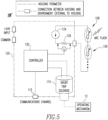
- Communication channel(s) 115 as well as the operation of arc flash detection module 108 and a shunt trip solenoid 110 that is included in some example embodiments of arc flash detection module 108, are detailed later herein with respect to FIG. 4 and FIG. 5 .
- circuit interrupters include frames 20 structured to accommodate the insertion of a plurality of modular accessory devices such as shunt trip, spring release, and under voltage relay devices, among others. These accessories are modular in the sense that any one of the accessory device types can be interchangeably inserted into any one of a number of accessory mountings 22 formed in the circuit interrupter frame 20.
- FIG. 3 two empty accessory mountings 22 are shown next to the accessory mounting 22 in which arc flash detection module 108 is mounted.
- Forming the frame 20 of circuit interrupter 100 with accessory mountings 22 enables the circuit interrupter 1 to be customized for the needs of each individual customer with easy-to-implement field upgrades. Accordingly, it should be understood that arc flash detection module 108 is structured to be inserted into an accessory mounting 22 formed in the frame 20 of circuit interrupter 1 as shown in FIG. 3 .
- FIGS. 4 and 5 show schematic diagrams of two embodiments 108' and 108" of the arc flash detection module 108 in accordance with example embodiments of the disclosed concept. Both embodiments 108' and 108" of arc flash detection module 108 can be referred to generally as arc flash detection module 108.
- arc flash detection module 108 As previously stated in the Background section, currently, only devices external to a circuit breaker can detect light from an arc flash event, and these known external arc flash detection devices can only force a trip of the circuit breaker by energizing yet another separate device, a shunt trip accessory. This setup of several external devices is expensive, requires a great deal of work to wire and mount all of the separate devices, and delays opening of the separable contacts 14 during an arc fault.
- embodiments 108' and 108" of arc flash accessory module 108 both include several of the same elements, with the primary distinction between module 108' and module 108" being the inclusion of shunt trip solenoid 110 in module 108", solenoid 110 being described in more detail herein below. While shunt trip solenoid 110 is included in FIG. 2 , it should be noted that either embodiment 108' or 108" of arc flash detection module 108 can be included in circuit interrupter 100, and that if embodiment 108' is included in circuit interrupter 100, then solenoid 110 will be omitted, and there will be no direct connection between arch flash module 108 and operating mechanism 12. Below, the features common to both arc flash accessory modules 108 are detailed first and discussed using the reference number 108, and the features unique to each of the embodiments 108' and 108" are detailed afterward using the respective reference numbers 108' and 108".
- both arc flash detection accessory modules 108 comprise a housing 120 (also denoted by the notation "housing perimeter" in the figure legends) that houses several components within the interior of the housing 120.
- both embodiments 108' and 108" include some components disposed externally to the housing 120, and as shown in the figures, the accessory housing 120 is also structured to include several points of connection or communication between the accessory housing 120 and the environment external to the housing 120.
- both arc flash accessory modules 108 include a plurality of series-connected light sensors 109 that are disposed externally to the housing 120, as well as externally to the frame 20 of the circuit interrupter 100, and are positioned to be exposed to the light of any arc flashes that originate from the circuit interrupter 100.
- light sensors 109 are light dependent resistors (LDRs), i.e. photoresistors, whose impedance decreases as any proximate light increases in brightness/intensity. Changes in the impedance of photoresistor light sensors 109 can be detected by using any one of many known circuits. For example, a current source 124 and a fixed resistor 126 can be placed in series with the light sensors 109 (as shown in FIGS.
- LDRs light dependent resistors
- the current source 124 is a 4-20 mA source.
- Both arc flash accessory modules 108 include a controller 130 and a two wire connection for connecting to a power source in order to power the current source 124 and the controller 130.
- the arc flash module 108 is designed to be used with standard power sources generally used to power digital control devices, such as +24V DC (as shown in FIGS. 4 and 5 ), or 115V/230V AC.
- Controller 130 can comprise, for example and without limitation, a microcontroller. Controller 130 implements digital logic in order to, for example and without limitation, monitor the voltage across fixed resistor 126, and communicates with electronic trip unit 16 via communication channel 115.
- communication channel 115 is a control area network (CAN) channel.
- CAN control area network
- Communication channel 115 can be used to implement communication standards other than CAN without departing from the scope of the disclosed concept.
- Communication channel 115 is a multi-wire connection that facilitates bilateral communication between controller 130 and electronic trip unit 16.
- Controller 130 in particular may transmit signals to electronic trip unit 16 that indicate, for example and without limitation, whether an arc flash has been detected by the arc flash module 108, how many light sensors 109 are activated, if the module 108 is enabled/turned off/in a standby mode, if the module 108 is healthy/working, if there is any error with the light sensors 109, or if any light sensors 109 have been added or removed.
- controller 130 is programmed to send an arc flash alert signal to electronic trip unit 16 if the resistance of light sensors 109 (as determined based on the voltage across fixed resistor 126) indicates the likely presence of arc flash light originating from the circuit interrupter 100.
- the electronic trip unit 16 is configured to then check the current through the circuit interrupter 100 using current sensor 18 (or another suitable mechanism). If the current through the circuit interrupter 100 is in excess of a predetermined acceptable threshold level, then the trip unit 16 can initiate a trip by actuating the operating mechanism 12. It will be appreciated that trip unit 16 can accept user input, and that a user may choose the threshold current that should be used to initiate a trip due to arc flash detection.
- controller 130 can be programmed to only send an arc flash alert signal to electronic trip unit 16 if the impedance of sensors 109 indicates the presence of light above a predetermined threshold intensity, i.e. an intensity indicative of an arc flash condition.
- module 108" includes a shunt trip solenoid 110 that is omitted from module 108'.
- Shunt trip solenoid 110 is operatively coupled to the operating mechanism 12 of circuit interrupter 100.
- the controller 130 of module 108" can energize the shunt trip solenoid 110 so that solenoid 110 can directly actuate operating mechanism 12 to open the separable contacts 18, rather than sending a signal to electronic trip unit 16 so that trip unit 16 has to actuate operating mechanism 12.
- shunt trip solenoid 110 in module 108" provides a mechanism whereby module 108" can directly actuate the operating mechanism 12 to open the separable contacts 18, without using the electronic trip unit 16 at all, whereas the electronic trip unit 16 must initiate the opening of the separable contacts 18 when module 108' is used.
- module 108 would be used instead of module 108', for example and without limitation, when it is desired to trip open the separable contacts 18 based only upon the detection of light (as opposed to the detection of both light and high current), and that module 108' would be used when both the detection of light and high current are desired for tripping open the separable contacts 18.
- the controller 130 transmits a signal that leads to the separable contacts 18 being tripped open if arc flash conditions are detected based on the monitoring of light sensors 109, but with module 108', the electronic trip unit 16 makes the final determination about whether to actuate the trip, whereas with module 108", the controller 130 makes the final determination about whether to actuate the trip.
- embodiment 108 does not require electronic trip unit 16 to trip open the separable contacts 18 in the event of arc flash detection
- bilateral communication between the controller 130 and the electronic trip unit 16 along communication channel 115 is still of value in embodiment 10"
- the controller 130 may need to communicate about various other matters, as described herein below.
- the controller 130 can use the voltage across fixed resistor 126 to determine what the current through the sensors 109 is in order to determine whether the sensors 109 are functioning properly. For example, if the controller 130 determines that the current through the sensors 109 is zero, then the controller 130 can issue an alert that the sensors should be evaluated to determine if the sensors 109 are disconnected or if a wire connecting the sensors 109 to the internal circuitry of module 108 is broken.
- the bilateral communication between the controller 130 and electronic trip unit 16 via communication channel 115 enables the trip unit 16 to tell the controller 130 that a trip has already been initiated, in which case the controller 130 can ignore any light detected by the sensors 109, as the light is likely attributable to arcing between the separable contacts 18 resulting from opening of the contacts 18.
- FIG. 6 a flowchart of a method 200 for tripping open a circuit interrupter based on the detection of an arc flash using an accessory arc flash detection module is shown, in accordance with example embodiments of the disclosed concept.
- the method of FIG. 6 may be employed, for example, with the circuit interrupter 100 shown in FIG. 2 and the arc flash detection modules 108 depicted in FIGS. 4 and 5 .
- the method may be employed in other devices as well without departing from the scope of the disclosed concept.
- the method begins at 201 where the arc flash detection module 108 is operatively coupled to the circuit interrupter 1. Due to the modular design of the arc flash detection module 108 and corresponding accessory mounting 22 formed in the frame 20 of circuit interrupter 100, operatively coupling the arc flash detection module 108 to the circuit interrupter 100 essentially only entails inserting the module 108 into the accessory mounting 22 of circuit interrupter 100.
- the controller 130 monitors the characteristics of the light sensors 109 to determine if the characteristics are indicative of the presence of an arc flash, i.e. the controller determines whether the intensity of any light sensed by light sensors 109 is great enough to be indicative of the presence of an arc flash.
- Monitoring the characteristics of the light sensors can comprise, for example and without limitation, monitoring the voltage across fixed resistor 126 in order to determine the impedance of the photoresistor light sensors 109. If the characteristics of light sensors 109 indicate detection of arc flash light, then the method proceeds to either step 203 or step 204, depending on whether embodiment 108' or embodiment 108" of arc flash detection module 108 is being used.
- step 203 the controller 130 transmits an arc flash alert signal to the electronic trip unit 16, and subsequently proceeds to 205, where the electronic trip unit 16 checks the current flowing through the circuit interrupter 1. If the current exceeds a predetermined threshold, then the trip unit 16 actuates the operating mechanism 12 to trip open the separable contacts 18. Referring back to step 202, if a change to the impedance of the light sensors 202 was detected and embodiment 108" is being used, then the method proceeds to 204, where the controller 130 energizes the shunt trip solenoid 110 in order to actuate the operating mechanism 12 to trip open the separable contacts 18.
Abstract
Description
- The disclosed concept relates generally to circuit interrupters, and in particular, to arc flash detection devices for use with circuit interrupters.
- Circuit interrupters, such as for example and without limitation, circuit breakers, are typically used to protect electrical circuitry from damage due to an overcurrent condition, such as an overload condition, a short circuit, or another fault condition, such as an arc fault or a ground fault. Circuit interrupters typically include separable contacts. The separable contacts may be operated either manually by way of an operator handle or automatically in response to a detected fault condition. Typically, such circuit interrupters include an operating mechanism, which is designed to rapidly open the separable contacts, and a trip mechanism, such as a trip unit, which senses a number of fault conditions to trip the separable contacts open automatically. Upon sensing a fault condition, the trip unit trips the operating mechanism to a trip state, which moves the separable contacts to their open position.
- In a circuit breaker where the insulation has deteriorated or where the breaker is overloaded and overheats, arcing can occur. Arcing can be detrimental to both the circuit interrupter itself and the electrical components connected to it. It is important to minimize the effects of arcing by tripping open the separable contacts as soon as possible after arcing is detected. Currently, only devices external to a circuit breaker can detect light from an arc flash event. In existing circuit breaker systems, these external arc flash detection devices must be wired to another external measurement device that measures the fault current from the event. When an output of light and high current are detected, the external arc flash detection device can force a trip of the circuit breaker by energizing a separate shunt trip accessory.
-
FIG. 1 shows an example of an existing circuit breaker system that uses an arc flash detection device external to the circuit breaker. The circuit interrupter 1 is structured to be electrically connected between LINE and LOAD side conductors. For example, the LINE side conductors may be upstream and the LOAD side conductors may be downstream in the power system the circuit interrupter is utilized in. The circuit interrupter 1 is structured to trip open or switch open to interrupt current flowing between the LINE and LOAD conductors in the event of a fault condition (e.g., without limitation, an arc fault). - Continuing to refer to
FIG. 1 , an external accessoryarc flash relay 8 is electrically connected to a number ofexternal light sensors 9 and an internalshunt trip accessory 10, and theshunt trip accessory 10 is operatively coupled to anoperating mechanism 12. When an output of light and high current produced by an arc flash are detected by theexternal light sensors 9 and/or the externalarc flash relay 8, thearc flash relay 8 can force a trip of the circuit interrupter 1 by energizing theshunt trip accessory 10, which in turn actuates theoperating mechanism 12 to open a pair ofseparable contacts 14. Theseparable contacts 14 are disposed between the LINE and LOAD conductors and are structured to physically separate when actuated by theoperating mechanism 12. Theoperating mechanism 12 is also electrically connected to anelectronic trip unit 16 which is structured to monitor power flowing through the circuit interrupter 1 via acurrent sensor 18 and/or other sensors and to detect other fault (i.e. non-arc fault) conditions based on the power flowing through the circuit interrupter 1. In addition to being structured to trip open theseparable contacts 14 upon being actuated by theshunt trip accessory 10 during an arc fault, theoperating mechanism 12 is also structured to initiate a trip after receiving a trip initiation signal output by theelectronic trip unit 16 upon detection of a fault condition other than an arc fault. While a single phase is illustrated in the circuit interrupter 1 ofFIG. 1 , and other circuit interrupters described herein, it will be appreciated that the circuit interrupters may have multiple phases, such as three phases, and may have corresponding components such as separable contacts and current sensors corresponding to each phase. - Compared to the time that it takes for the
trip unit 16 to energize the trip actuator of theoperating mechanism 12 to open theseparable contacts 14 when a non-arc fault is detected, using ashunt trip 10 to open the breaker 1 in the event of an arc fault as the system shown inFIG. 1 does delays opening time, thus leading to increased arcing time. In addition, the need for several external devices in this particular arc flash detection setup is very expensive, and a great deal of work is required to wire and mount these devices for arc flash detection. - There is thus room for improvement in systems and methods used to detect arc flash events and trip circuit interrupters quickly based on detection of arc flash events.
- These needs and others are met by embodiments of the disclosed concept in which an accessory arc flash detection module for use with a circuit interrupter includes a housing structured to be installed within the circuit interrupter, and includes light sensors structured to be disposed externally to the circuit interrupter in order to detect arc flash events. The arc flash accessory module is configured to communicate with an electronic trip unit of the circuit interrupter, and can either indirectly or directly initiate a trip of the circuit interrupter upon detection of an arc flash by the light sensors.
- In accordance with one aspect of the disclosed concept, an arc flash detection module for use in a circuit interrupter comprises a housing, a plurality of light sensors disposed externally to the housing, a controller configured to monitor a number of characteristics of the light sensors, and a communication channel configured to facilitate electrical communication between the controller and an electronic trip unit of the circuit interrupter. The arc flash detection module is configured to be coupled to a frame of the circuit interrupter such that the housing is disposed within an interior of the circuit interrupter.
- In accordance with another aspect of the disclosed concept, a circuit interrupter comprises a frame, a line side structured to electrically connect to a power source, a load side structured to electrically connect to a load, separable contacts electrically connected between the line side and the load side, an operating mechanism structured to open and close the separable contacts, an electronic trip unit structured to actuate the operating mechanism, and an arc flash detection module in electrical communication with the electronic trip unit. The arc flash detection module comprises a housing, a plurality of light sensors disposed externally to the housing, a controller configured to monitor a number of characteristics of the light sensors, and a communication channel configured to facilitate electrical communication between the controller and an electronic trip unit of the circuit interrupter. The arc flash detection module is configured to be coupled to the frame of the circuit interrupter such that the housing is disposed within an interior of the circuit interrupter.
- In accordance with another aspect of the disclosed concept, a method of tripping open a circuit interrupter comprises first operatively coupling an arc flash detection module to the circuit interrupter. The arc flash detection module comprises a housing, a plurality of light sensors disposed externally to the housing, a controller configured to monitor a number of characteristics of the light sensors, and a communication channel configured to facilitate electrical communication between the controller and an electronic trip unit of the circuit interrupter. The method further comprises using the controller to monitor characteristics of the light sensors to determine if changes to the characteristics have occurred, and using the controller to actuate an operating mechanism of the circuit interrupter to open separable contacts of the circuit interrupter if the monitoring indicates that arc flash conditions exist.
- A full understanding of the disclosed concept can be gained from the following description of the preferred embodiments when read in conjunction with the accompanying drawings in which:
-
FIG. 1 is a schematic diagram of a circuit interrupter connected to an external arc flash relay device, representative of known arc flash detection systems; -
FIG. 2 is a schematic diagram of a circuit interrupter including an internal arc flash detection module, in accordance with example embodiments of the disclosed concept; -
FIG. 3 is a diagram of the exterior of the circuit interrupter shown inFIG. 2 ; -
FIG. 4 is a schematic diagram of a first variation of the arc flash detection module for use with the circuit interrupter shown inFIG. 2 , in accordance with an example embodiment of the disclosed concept; -
FIG. 5 is a schematic diagram of a second variation of the arc flash detection module for use with the circuit interrupter shown inFIG. 2 , in accordance with an example embodiment of the disclosed concept; and -
FIG. 6 is a flow chart of a method for tripping open a circuit interrupter based on the detection of an arc flash using an arc flash detection module installed within a circuit breaker, in accordance with example embodiments of the disclosed concept. - As used herein, the singular form of "a", "an", and "the" include plural references unless the context clearly dictates otherwise.
- As used herein, the term "number" shall mean one or an integer greater than one (i.e., a plurality).
- Directional phrases used herein, such as, for example, left, right, front, back, top, bottom and derivatives thereof, relate to the orientation of the elements shown in the drawings and are not limiting upon the claims unless expressly recited therein.
- As used herein, the term "controller" shall mean a number of programmable analog and/or digital devices (including an associated memory part or portion) that can store, retrieve, execute and process data (e.g., software routines and/or information used by such routines), including, without limitation, a field programmable gate array (FPGA), a complex programmable logic device (CPLD), a programmable system on a chip (PSOC), an application specific integrated circuit (ASIC), a microprocessor, a microcontroller, a programmable logic controller, or any other suitable processing device or apparatus. The memory portion can be any one or more of a variety of types of internal and/or external storage media such as, without limitation, RAM, ROM, EPROM(s), EEPROM(s), FLASH, and the like that provide a storage register, i.e., a non-transitory machine readable medium, for data and program code storage such as in the fashion of an internal storage area of a computer, and can be volatile memory or nonvolatile memory.
- As employed herein, the statement that two or more parts are "coupled" together shall mean that the parts are joined together either directly or joined through one or more intermediate parts.
-
FIG. 2 is a schematic diagram of a circuit interrupter 100 (e.g., without limitation, a circuit breaker) in accordance with example embodiments of the disclosed concept. Thecircuit interrupter 100 includes several of the same features as the circuit interrupter 1 shown inFIG. 1 , and it will be appreciated that components with the same reference numbers in multiple figures function substantially the same. In contrast with circuit interrupter 1 shown inFIG. 1 ,circuit interrupter 100 shown inFIG. 2 includes an accessory arcflash detection module 108 disposed internally to thecircuit interrupter 100, instead of thearc flash relay 8 disposed externally to circuit interrupter 1 inFIG. 1 . The arcflash detection module 108 can communicate with a number ofexternal light sensors 109 as well as components internal to circuit interrupter 100 (e.g. electronic trip unit 16) via a number ofcommunication channels 115. Communication channel(s) 115, as well as the operation of arcflash detection module 108 and ashunt trip solenoid 110 that is included in some example embodiments of arcflash detection module 108, are detailed later herein with respect toFIG. 4 andFIG. 5 . - Referring now to
FIG. 3 , some circuit interrupters (such as circuit interrupter 100) includeframes 20 structured to accommodate the insertion of a plurality of modular accessory devices such as shunt trip, spring release, and under voltage relay devices, among others. These accessories are modular in the sense that any one of the accessory device types can be interchangeably inserted into any one of a number ofaccessory mountings 22 formed in thecircuit interrupter frame 20. InFIG. 3 , twoempty accessory mountings 22 are shown next to theaccessory mounting 22 in which arcflash detection module 108 is mounted. Forming theframe 20 ofcircuit interrupter 100 withaccessory mountings 22 enables the circuit interrupter 1 to be customized for the needs of each individual customer with easy-to-implement field upgrades. Accordingly, it should be understood that arcflash detection module 108 is structured to be inserted into anaccessory mounting 22 formed in theframe 20 of circuit interrupter 1 as shown inFIG. 3 . -
FIGS. 4 and5 show schematic diagrams of twoembodiments 108' and 108" of the arcflash detection module 108 in accordance with example embodiments of the disclosed concept. Bothembodiments 108' and 108" of arcflash detection module 108 can be referred to generally as arcflash detection module 108. As previously stated in the Background section, currently, only devices external to a circuit breaker can detect light from an arc flash event, and these known external arc flash detection devices can only force a trip of the circuit breaker by energizing yet another separate device, a shunt trip accessory. This setup of several external devices is expensive, requires a great deal of work to wire and mount all of the separate devices, and delays opening of theseparable contacts 14 during an arc fault. The devices disclosed herein (i.e.circuit interrupter 100, arc flash detection modules 108) provide a better, more streamlined solution and a novel method for bringing arc flash detection and measurement functions into circuit breakers and opening circuit breakers faster during an arc fault event, due to the arcflash detection module 108 being either in direct communication with thetrip unit 16 or directly operatively coupled to theoperating mechanism 12, as detailed further herein below. - Still referring to
FIG. 4 andFIG. 5 ,embodiments 108' and 108" of arcflash accessory module 108 both include several of the same elements, with the primary distinction between module 108' andmodule 108" being the inclusion ofshunt trip solenoid 110 inmodule 108",solenoid 110 being described in more detail herein below. Whileshunt trip solenoid 110 is included inFIG. 2 , it should be noted that eitherembodiment 108' or 108" of arcflash detection module 108 can be included incircuit interrupter 100, and that if embodiment 108' is included incircuit interrupter 100, then solenoid 110 will be omitted, and there will be no direct connection betweenarch flash module 108 andoperating mechanism 12. Below, the features common to both arcflash accessory modules 108 are detailed first and discussed using thereference number 108, and the features unique to each of theembodiments 108' and 108" are detailed afterward using therespective reference numbers 108' and 108". - Continuing to refer to both
FIG. 4 andFIG. 5 , both arc flashdetection accessory modules 108 comprise a housing 120 (also denoted by the notation "housing perimeter" in the figure legends) that houses several components within the interior of thehousing 120. In addition, bothembodiments 108' and 108" include some components disposed externally to thehousing 120, and as shown in the figures, theaccessory housing 120 is also structured to include several points of connection or communication between theaccessory housing 120 and the environment external to thehousing 120. For example, both arcflash accessory modules 108 include a plurality of series-connectedlight sensors 109 that are disposed externally to thehousing 120, as well as externally to theframe 20 of thecircuit interrupter 100, and are positioned to be exposed to the light of any arc flashes that originate from thecircuit interrupter 100. - In an exemplary embodiment,
light sensors 109 are light dependent resistors (LDRs), i.e. photoresistors, whose impedance decreases as any proximate light increases in brightness/intensity. Changes in the impedance of photoresistorlight sensors 109 can be detected by using any one of many known circuits. For example, acurrent source 124 and a fixedresistor 126 can be placed in series with the light sensors 109 (as shown inFIGS. 3 and4 ) in order to form a voltage divider, since the fixed resistance ofresistor 126 and the fixed current provided bycurrent source 124 will result in the voltage acrossresistor 126 changing to offset any changes in the impedance oflight sensors 109 resulting from light-producing events that originate in the circuit interrupter 1, in accordance with Ohm's law: V=IR. In an exemplary embodiment, thecurrent source 124 is a 4-20 mA source. - Both arc flash
accessory modules 108 include acontroller 130 and a two wire connection for connecting to a power source in order to power thecurrent source 124 and thecontroller 130. In an exemplary embodiment, thearc flash module 108 is designed to be used with standard power sources generally used to power digital control devices, such as +24V DC (as shown inFIGS. 4 and5 ), or 115V/230V AC.Controller 130 can comprise, for example and without limitation, a microcontroller.Controller 130 implements digital logic in order to, for example and without limitation, monitor the voltage across fixedresistor 126, and communicates withelectronic trip unit 16 viacommunication channel 115. In an exemplary embodiment,communication channel 115 is a control area network (CAN) channel. However, it will be appreciated thatcommunication channel 115 can be used to implement communication standards other than CAN without departing from the scope of the disclosed concept.Communication channel 115 is a multi-wire connection that facilitates bilateral communication betweencontroller 130 andelectronic trip unit 16.Controller 130 in particular may transmit signals toelectronic trip unit 16 that indicate, for example and without limitation, whether an arc flash has been detected by thearc flash module 108, how manylight sensors 109 are activated, if themodule 108 is enabled/turned off/in a standby mode, if themodule 108 is healthy/working, if there is any error with thelight sensors 109, or if anylight sensors 109 have been added or removed. - Referring now specifically to embodiment 108' shown in
FIG. 4 ,controller 130 is programmed to send an arc flash alert signal toelectronic trip unit 16 if the resistance of light sensors 109 (as determined based on the voltage across fixed resistor 126) indicates the likely presence of arc flash light originating from thecircuit interrupter 100. Theelectronic trip unit 16 is configured to then check the current through thecircuit interrupter 100 using current sensor 18 (or another suitable mechanism). If the current through thecircuit interrupter 100 is in excess of a predetermined acceptable threshold level, then thetrip unit 16 can initiate a trip by actuating theoperating mechanism 12. It will be appreciated thattrip unit 16 can accept user input, and that a user may choose the threshold current that should be used to initiate a trip due to arc flash detection. For example and without limitation, it is likely that a current of 2 to 10 times the rated normal operating current would be an appropriate threshold level for initiating a trip due to an arc flash. In addition, it will be appreciated thatcontroller 130 can be programmed to only send an arc flash alert signal toelectronic trip unit 16 if the impedance ofsensors 109 indicates the presence of light above a predetermined threshold intensity, i.e. an intensity indicative of an arc flash condition. - Referring now specifically to
embodiment 108" shown inFIG. 5 ,module 108" includes ashunt trip solenoid 110 that is omitted from module 108'.Shunt trip solenoid 110 is operatively coupled to theoperating mechanism 12 ofcircuit interrupter 100. In contrast to module 108', after determining that the impedance ofsensors 109 indicates the presence of arc flash light, thecontroller 130 ofmodule 108" can energize theshunt trip solenoid 110 so thatsolenoid 110 can directly actuateoperating mechanism 12 to open theseparable contacts 18, rather than sending a signal toelectronic trip unit 16 so thattrip unit 16 has to actuateoperating mechanism 12. Thus, the inclusion ofshunt trip solenoid 110 inmodule 108" provides a mechanism wherebymodule 108" can directly actuate theoperating mechanism 12 to open theseparable contacts 18, without using theelectronic trip unit 16 at all, whereas theelectronic trip unit 16 must initiate the opening of theseparable contacts 18 when module 108' is used. - It is expected that
module 108" would be used instead of module 108', for example and without limitation, when it is desired to trip open theseparable contacts 18 based only upon the detection of light (as opposed to the detection of both light and high current), and that module 108' would be used when both the detection of light and high current are desired for tripping open theseparable contacts 18. It will be appreciated that in both module 108' andmodule 108", thecontroller 130 transmits a signal that leads to theseparable contacts 18 being tripped open if arc flash conditions are detected based on the monitoring oflight sensors 109, but with module 108', theelectronic trip unit 16 makes the final determination about whether to actuate the trip, whereas withmodule 108", thecontroller 130 makes the final determination about whether to actuate the trip. It will also be appreciated that, althoughembodiment 108" does not requireelectronic trip unit 16 to trip open theseparable contacts 18 in the event of arc flash detection, bilateral communication between thecontroller 130 and theelectronic trip unit 16 alongcommunication channel 115 is still of value inembodiment 10", as it may be desired for thecontroller 130 to inform theelectronic trip unit 16 that thecontroller 130 initiated a trip due to a detected arc flash, and thecontroller 130 and thetrip unit 16 may need to communicate about various other matters, as described herein below. - Referring again to both embodiments of arc
flash accessory module 108, in addition to evaluating the voltage across fixedresistor 126 to determine the presence or lack thereof of an arc flash, thecontroller 130 can use the voltage across fixedresistor 126 to determine what the current through thesensors 109 is in order to determine whether thesensors 109 are functioning properly. For example, if thecontroller 130 determines that the current through thesensors 109 is zero, then thecontroller 130 can issue an alert that the sensors should be evaluated to determine if thesensors 109 are disconnected or if a wire connecting thesensors 109 to the internal circuitry ofmodule 108 is broken. Furthermore, the bilateral communication between thecontroller 130 andelectronic trip unit 16 viacommunication channel 115 enables thetrip unit 16 to tell thecontroller 130 that a trip has already been initiated, in which case thecontroller 130 can ignore any light detected by thesensors 109, as the light is likely attributable to arcing between theseparable contacts 18 resulting from opening of thecontacts 18. - Referring now to
FIG. 6 , a flowchart of amethod 200 for tripping open a circuit interrupter based on the detection of an arc flash using an accessory arc flash detection module is shown, in accordance with example embodiments of the disclosed concept. The method ofFIG. 6 may be employed, for example, with thecircuit interrupter 100 shown inFIG. 2 and the arcflash detection modules 108 depicted inFIGS. 4 and5 . However, it will be appreciated that the method may be employed in other devices as well without departing from the scope of the disclosed concept. - The method begins at 201 where the arc
flash detection module 108 is operatively coupled to the circuit interrupter 1. Due to the modular design of the arcflash detection module 108 and corresponding accessory mounting 22 formed in theframe 20 ofcircuit interrupter 100, operatively coupling the arcflash detection module 108 to thecircuit interrupter 100 essentially only entails inserting themodule 108 into the accessory mounting 22 ofcircuit interrupter 100. At 202, thecontroller 130 monitors the characteristics of thelight sensors 109 to determine if the characteristics are indicative of the presence of an arc flash, i.e. the controller determines whether the intensity of any light sensed bylight sensors 109 is great enough to be indicative of the presence of an arc flash. Monitoring the characteristics of the light sensors can comprise, for example and without limitation, monitoring the voltage across fixedresistor 126 in order to determine the impedance of the photoresistorlight sensors 109. If the characteristics oflight sensors 109 indicate detection of arc flash light, then the method proceeds to either step 203 or step 204, depending on whether embodiment 108' orembodiment 108" of arcflash detection module 108 is being used. - If embodiment 108' is being used, then the method proceeds to 203, where the
controller 130 transmits an arc flash alert signal to theelectronic trip unit 16, and subsequently proceeds to 205, where theelectronic trip unit 16 checks the current flowing through the circuit interrupter 1. If the current exceeds a predetermined threshold, then thetrip unit 16 actuates theoperating mechanism 12 to trip open theseparable contacts 18. Referring back to step 202, if a change to the impedance of thelight sensors 202 was detected andembodiment 108" is being used, then the method proceeds to 204, where thecontroller 130 energizes theshunt trip solenoid 110 in order to actuate theoperating mechanism 12 to trip open theseparable contacts 18. - While specific embodiments of the disclosed concept have been described in detail, it will be appreciated by those skilled in the art that various modifications and alternatives to those details could be developed in light of the overall teachings of the disclosure. Accordingly, the particular arrangements disclosed are meant to be illustrative only and not limiting as to the scope of the disclosed concept which is to be given the full breadth of the claims appended and any and all equivalents thereof.
Claims (15)
- An arc flash detection module for use in a circuit interrupter, the arc flash detection module comprising:a housing;a plurality of light sensors disposed externally to the housing;a controller configured to monitor a number of characteristics of the light sensors; anda communication channel configured to facilitate electrical communication between the controller and an electronic trip unit of the circuit interrupter,wherein the arc flash detection module is configured to be coupled to a frame of the circuit interrupter such that the housing is disposed within an interior of the circuit interrupter.
- The arc flash detection module of claim 1,
wherein the controller is configured to transmit an arc flash alert signal to the electronic trip unit if the number of characteristics of the light sensors indicates the presence of an arc flash condition. - The arc flash detection module of claim 2, further comprising:a current source electrically connected in series with the light sensors; anda fixed resistor electrically connected in series with the current source and the light sensors,wherein the plurality of light sensors are photoresistors whose impedance changes when light proximate to the light sensors changes in intensity,wherein the controller is configured to monitor the voltage across the fixed resistor and to transmit the arc flash alert signal based on the voltage across the fixed resistor.
- The arc flash detection module of claim 1, further comprising:a shunt trip solenoid operatively coupled to an operating mechanism of the circuit interrupter,wherein the controller is configured to energize the shunt trip solenoid to actuate the operating mechanism to trip open separable contacts of the circuit interrupter if the number of characteristics of the light sensors indicates the presence of an arc flash.
- The arc flash detection module of claim 4, wherein the shunt trip solenoid is directly operatively coupled to the operating mechanism such that the electronic trip unit does not actuate the operating mechanism when the number of characteristics of the light sensors indicates the presence of an arc flash.
- The arc flash detection module of claim 4, further comprising:a current source electrically connected in series with the light sensors; anda fixed resistor electrically connected in series with the current source and the light sensors,wherein the light sensors are photoresistors whose impedance changes when light proximate to the light sensors changes in intensity,wherein the controller is configured to monitor the voltage across the fixed resistor and to energize the shunt trip solenoid to actuate the operating mechanism based on the voltage across the fixed resistor.
- A circuit interrupter comprising:a frame;a line side structured to electrically connect to a power source;a load side structured to electrically connect to a load;separable contacts electrically connected between the line side and the load side;an operating mechanism structured to open and close the separable contacts;an electronic trip unit structured to actuate the operating mechanism; andan arc flash detection module in electrical communication with the electronic trip unit, the arc flash detection module comprising:a housing;a plurality of light sensors disposed externally to the housing;a controller configured to monitor a number of characteristics of the light sensors; anda communication channel configured to facilitate electrical communication between the controller and an electronic trip unit of the circuit interrupter,wherein the arc flash detection module is configured to be coupled to the frame of the circuit interrupter such that the housing is disposed within an interior of the circuit interrupter.
- The circuit interrupter of claim 7,
wherein the controller is configured to transmit an arc flash alert signal to the electronic trip unit if the number of characteristics of the light sensors indicates the presence of an arc flash condition. - The circuit interrupter of claim 7, wherein the arc flash detection module further comprises:a shunt trip solenoid operatively coupled to the operating mechanism of the circuit interrupter,wherein the controller is configured to energize the shunt trip solenoid to actuate the operating mechanism to trip open separable contacts if the number of characteristics of the light sensors indicates the presence of an arc flash.
- The circuit interrupter of claim 9, wherein the shunt trip solenoid is directly operatively coupled to the operating mechanism such that the electronic trip unit does not actuate the operating mechanism when the number of characteristics of the light sensors indicates the presence of an arc flash.
- A method of tripping open a circuit interrupter, the method comprising:operatively coupling an arc flash detection module to the circuit interrupter, the arc flash detection module comprising:a housing;a plurality of light sensors disposed externally to the housing;a controller configured to monitor a number of characteristics of the light sensors; anda communication channel configured to facilitate electrical communication between the controller and an electronic trip unit of the circuit interrupter;monitoring, with the controller, characteristics of the light sensors to determine if changes to the characteristics have occurred; andactuating an operating mechanism of the circuit interrupter to open separable contacts of the circuit interrupter, with the controller, if the monitoring indicates that arc flash conditions exist.
- The method of claim 11, wherein operatively coupling the arc flash detection module to the circuit interrupter comprises inserting the arc flash detection module into an accessory mounting formed within a frame of the circuit breaker such that the housing is disposed within an interior of the circuit interrupter.
- The method of claim 11, further comprising:transmitting, with the controller, an arc flash alert signal to the electronic trip unit; anddetermining, with the electronic trip unit, a current flowing through the circuit interrupter,wherein the actuating of the operating mechanism to open the separable contacts only occurs if the electronic trip unit determines that the current exceeds a predetermined threshold.
- The method of claim 11, wherein the arc flash detection module further comprises a shunt trip solenoid in electrical communication with the controller, the method further comprising:
energizing the shunt trip solenoid, with the controller, to actuate the operating mechanism to trip open the separable contacts if the monitoring indicates that arc flash conditions exist. - The method of claim 11, wherein the arc flash detection module further comprises:a current source electrically connected in series with the light sensors; anda fixed resistor electrically connected in series with the current source and the light sensors,wherein the plurality of light sensors are photoresistors whose impedance changes when light proximate to the light sensors changes in intensity, andwherein the monitoring comprises determining a voltage across the fixed resistor.
Applications Claiming Priority (1)
| Application Number | Priority Date | Filing Date | Title |
|---|---|---|---|
| US17/548,802 US11855435B2 (en) | 2021-12-13 | 2021-12-13 | Arc flash accessory module |
Publications (1)
| Publication Number | Publication Date |
|---|---|
| EP4195431A1 true EP4195431A1 (en) | 2023-06-14 |
Family
ID=84369533
Family Applications (1)
| Application Number | Title | Priority Date | Filing Date |
|---|---|---|---|
| EP22210787.2A Pending EP4195431A1 (en) | 2021-12-13 | 2022-12-01 | Arc flash accessory module |
Country Status (3)
| Country | Link |
|---|---|
| US (1) | US11855435B2 (en) |
| EP (1) | EP4195431A1 (en) |
| CN (1) | CN116264383A (en) |
Citations (3)
| Publication number | Priority date | Publication date | Assignee | Title |
|---|---|---|---|---|
| US20120320486A1 (en) * | 2011-06-20 | 2012-12-20 | Lagree James L | Arc flash system for a power circuit |
| US20170138999A1 (en) * | 2015-11-12 | 2017-05-18 | G2 Power Co., Ltd. | Arc flash detection device having optic fiber sensor |
| US20180145496A1 (en) * | 2016-11-18 | 2018-05-24 | Schweitzer Engineering Laboratories, Inc. | Methods and systems for evaluating arc flash exposure hazard |
Family Cites Families (3)
| Publication number | Priority date | Publication date | Assignee | Title |
|---|---|---|---|---|
| EP2510367A4 (en) * | 2009-12-11 | 2014-07-23 | Alstom Technology Ltd | Method for arc detection and devices thereof |
| US8564915B2 (en) * | 2010-09-08 | 2013-10-22 | General Electric Company | Methods, systems, and apparatus for detecting arc flash events using light and time discrimination |
| CN108882430A (en) * | 2017-05-16 | 2018-11-23 | 林品芝 | Has the LED lamp of automatic dimming function |
-
2021
- 2021-12-13 US US17/548,802 patent/US11855435B2/en active Active
-
2022
- 2022-12-01 EP EP22210787.2A patent/EP4195431A1/en active Pending
- 2022-12-12 CN CN202211596513.4A patent/CN116264383A/en active Pending
Patent Citations (3)
| Publication number | Priority date | Publication date | Assignee | Title |
|---|---|---|---|---|
| US20120320486A1 (en) * | 2011-06-20 | 2012-12-20 | Lagree James L | Arc flash system for a power circuit |
| US20170138999A1 (en) * | 2015-11-12 | 2017-05-18 | G2 Power Co., Ltd. | Arc flash detection device having optic fiber sensor |
| US20180145496A1 (en) * | 2016-11-18 | 2018-05-24 | Schweitzer Engineering Laboratories, Inc. | Methods and systems for evaluating arc flash exposure hazard |
Also Published As
| Publication number | Publication date |
|---|---|
| US11855435B2 (en) | 2023-12-26 |
| CN116264383A (en) | 2023-06-16 |
| US20230187919A1 (en) | 2023-06-15 |
Similar Documents
| Publication | Publication Date | Title |
|---|---|---|
| US8279565B2 (en) | Methods and systems relating to overcurrent circuit protection | |
| CA2484812C (en) | Ground-fault monitor for multiple circuits | |
| RU2633518C2 (en) | Method for detecting arc short circuits with application of switched elements in socket | |
| US4331999A (en) | Circuit interrupter with digital trip unit and power supply | |
| US5136457A (en) | Processor controlled circuit breaker trip system having an intelligent rating plug | |
| EP1385015B1 (en) | Tester for a plurality of circuit breakers having a range of rated currents and multiple trip functions | |
| US6473281B1 (en) | Automatic protection device with ground fault annunciation | |
| US4338647A (en) | Circuit interrupter with digital trip unit and optically-coupled data input/output system | |
| US6459557B1 (en) | Configurable single/multi-phase overload relay | |
| KR102232027B1 (en) | Digtal-zero relay controller for motor control and dual control method usign the same controller | |
| EP1972045A1 (en) | Receptacle providing sustained excessive voltage protection | |
| CN101752148B (en) | Circuit breaker with selectivity | |
| US7116538B2 (en) | Modular overload relay system | |
| EP0333412B1 (en) | Circuit breakers test device | |
| US11855435B2 (en) | Arc flash accessory module | |
| CN110718894B (en) | Low-voltage circuit breaker and method | |
| US6034447A (en) | Connector for consumer networks | |
| US7327052B2 (en) | Modular connecting system for protecting an electrical load in a bus system | |
| EP2477292B1 (en) | Automatic reset discrimination system and method for a self powered electronic protection device | |
| CA2919627A1 (en) | Interlocking outlet and associated method | |
| US11183831B2 (en) | System and method for discerning arcing in electrical wiring | |
| CN113258668A (en) | Remote driver, device and test method | |
| CN215817511U (en) | Medical equipment and protection circuit thereof | |
| US7092228B1 (en) | Low-voltage power breaker with a rating plug | |
| CN111200273A (en) | Protective switching device for low-voltage circuits for detecting series fault arcs |
Legal Events
| Date | Code | Title | Description |
|---|---|---|---|
| PUAI | Public reference made under article 153(3) epc to a published international application that has entered the european phase |
Free format text: ORIGINAL CODE: 0009012 |
|
| STAA | Information on the status of an ep patent application or granted ep patent |
Free format text: STATUS: THE APPLICATION HAS BEEN PUBLISHED |
|
| AK | Designated contracting states |
Kind code of ref document: A1 Designated state(s): AL AT BE BG CH CY CZ DE DK EE ES FI FR GB GR HR HU IE IS IT LI LT LU LV MC ME MK MT NL NO PL PT RO RS SE SI SK SM TR |
|
| STAA | Information on the status of an ep patent application or granted ep patent |
Free format text: STATUS: REQUEST FOR EXAMINATION WAS MADE |
|
| 17P | Request for examination filed |
Effective date: 20231204 |
|
| RBV | Designated contracting states (corrected) |
Designated state(s): AL AT BE BG CH CY CZ DE DK EE ES FI FR GB GR HR HU IE IS IT LI LT LU LV MC ME MK MT NL NO PL PT RO RS SE SI SK SM TR |