EP4195424A1 - Floating connector and floating connector assembly - Google Patents
Floating connector and floating connector assembly Download PDFInfo
- Publication number
- EP4195424A1 EP4195424A1 EP22204379.6A EP22204379A EP4195424A1 EP 4195424 A1 EP4195424 A1 EP 4195424A1 EP 22204379 A EP22204379 A EP 22204379A EP 4195424 A1 EP4195424 A1 EP 4195424A1
- Authority
- EP
- European Patent Office
- Prior art keywords
- connector
- housing
- axis
- spherical
- ground terminal
- Prior art date
- Legal status (The legal status is an assumption and is not a legal conclusion. Google has not performed a legal analysis and makes no representation as to the accuracy of the status listed.)
- Granted
Links
- 230000002093 peripheral effect Effects 0.000 claims description 2
- 238000003780 insertion Methods 0.000 description 48
- 230000037431 insertion Effects 0.000 description 48
- 230000035515 penetration Effects 0.000 description 34
- 238000003384 imaging method Methods 0.000 description 18
- 238000004382 potting Methods 0.000 description 8
- 239000011347 resin Substances 0.000 description 5
- 229920005989 resin Polymers 0.000 description 5
- 230000008859 change Effects 0.000 description 4
- 239000000758 substrate Substances 0.000 description 4
- 238000005304 joining Methods 0.000 description 3
- 239000003566 sealing material Substances 0.000 description 2
- XLYOFNOQVPJJNP-UHFFFAOYSA-N water Substances O XLYOFNOQVPJJNP-UHFFFAOYSA-N 0.000 description 2
- 238000005452 bending Methods 0.000 description 1
- 238000005520 cutting process Methods 0.000 description 1
- 230000007246 mechanism Effects 0.000 description 1
- 238000000034 method Methods 0.000 description 1
- 230000004048 modification Effects 0.000 description 1
- 238000012986 modification Methods 0.000 description 1
- 230000000149 penetrating effect Effects 0.000 description 1
- 230000008569 process Effects 0.000 description 1
- 238000005549 size reduction Methods 0.000 description 1
Images


Classifications
-
- H—ELECTRICITY
- H01—ELECTRIC ELEMENTS
- H01R—ELECTRICALLY-CONDUCTIVE CONNECTIONS; STRUCTURAL ASSOCIATIONS OF A PLURALITY OF MUTUALLY-INSULATED ELECTRICAL CONNECTING ELEMENTS; COUPLING DEVICES; CURRENT COLLECTORS
- H01R24/00—Two-part coupling devices, or either of their cooperating parts, characterised by their overall structure
- H01R24/005—Two-part coupling devices, or either of their cooperating parts, characterised by their overall structure requiring successive relative motions to complete the coupling, e.g. bayonet type
-
- H—ELECTRICITY
- H01—ELECTRIC ELEMENTS
- H01R—ELECTRICALLY-CONDUCTIVE CONNECTIONS; STRUCTURAL ASSOCIATIONS OF A PLURALITY OF MUTUALLY-INSULATED ELECTRICAL CONNECTING ELEMENTS; COUPLING DEVICES; CURRENT COLLECTORS
- H01R24/00—Two-part coupling devices, or either of their cooperating parts, characterised by their overall structure
- H01R24/38—Two-part coupling devices, or either of their cooperating parts, characterised by their overall structure having concentrically or coaxially arranged contacts
- H01R24/40—Two-part coupling devices, or either of their cooperating parts, characterised by their overall structure having concentrically or coaxially arranged contacts specially adapted for high frequency
-
- H—ELECTRICITY
- H01—ELECTRIC ELEMENTS
- H01R—ELECTRICALLY-CONDUCTIVE CONNECTIONS; STRUCTURAL ASSOCIATIONS OF A PLURALITY OF MUTUALLY-INSULATED ELECTRICAL CONNECTING ELEMENTS; COUPLING DEVICES; CURRENT COLLECTORS
- H01R13/00—Details of coupling devices of the kinds covered by groups H01R12/70 or H01R24/00 - H01R33/00
- H01R13/02—Contact members
-
- H—ELECTRICITY
- H01—ELECTRIC ELEMENTS
- H01R—ELECTRICALLY-CONDUCTIVE CONNECTIONS; STRUCTURAL ASSOCIATIONS OF A PLURALITY OF MUTUALLY-INSULATED ELECTRICAL CONNECTING ELEMENTS; COUPLING DEVICES; CURRENT COLLECTORS
- H01R13/00—Details of coupling devices of the kinds covered by groups H01R12/70 or H01R24/00 - H01R33/00
- H01R13/46—Bases; Cases
- H01R13/502—Bases; Cases composed of different pieces
-
- H—ELECTRICITY
- H01—ELECTRIC ELEMENTS
- H01R—ELECTRICALLY-CONDUCTIVE CONNECTIONS; STRUCTURAL ASSOCIATIONS OF A PLURALITY OF MUTUALLY-INSULATED ELECTRICAL CONNECTING ELEMENTS; COUPLING DEVICES; CURRENT COLLECTORS
- H01R13/00—Details of coupling devices of the kinds covered by groups H01R12/70 or H01R24/00 - H01R33/00
- H01R13/62—Means for facilitating engagement or disengagement of coupling parts or for holding them in engagement
- H01R13/629—Additional means for facilitating engagement or disengagement of coupling parts, e.g. aligning or guiding means, levers, gas pressure electrical locking indicators, manufacturing tolerances
- H01R13/631—Additional means for facilitating engagement or disengagement of coupling parts, e.g. aligning or guiding means, levers, gas pressure electrical locking indicators, manufacturing tolerances for engagement only
- H01R13/6315—Additional means for facilitating engagement or disengagement of coupling parts, e.g. aligning or guiding means, levers, gas pressure electrical locking indicators, manufacturing tolerances for engagement only allowing relative movement between coupling parts, e.g. floating connection
-
- H—ELECTRICITY
- H01—ELECTRIC ELEMENTS
- H01R—ELECTRICALLY-CONDUCTIVE CONNECTIONS; STRUCTURAL ASSOCIATIONS OF A PLURALITY OF MUTUALLY-INSULATED ELECTRICAL CONNECTING ELEMENTS; COUPLING DEVICES; CURRENT COLLECTORS
- H01R13/00—Details of coupling devices of the kinds covered by groups H01R12/70 or H01R24/00 - H01R33/00
- H01R13/62—Means for facilitating engagement or disengagement of coupling parts or for holding them in engagement
- H01R13/639—Additional means for holding or locking coupling parts together, after engagement, e.g. separate keylock, retainer strap
-
- H—ELECTRICITY
- H01—ELECTRIC ELEMENTS
- H01R—ELECTRICALLY-CONDUCTIVE CONNECTIONS; STRUCTURAL ASSOCIATIONS OF A PLURALITY OF MUTUALLY-INSULATED ELECTRICAL CONNECTING ELEMENTS; COUPLING DEVICES; CURRENT COLLECTORS
- H01R12/00—Structural associations of a plurality of mutually-insulated electrical connecting elements, specially adapted for printed circuits, e.g. printed circuit boards [PCB], flat or ribbon cables, or like generally planar structures, e.g. terminal strips, terminal blocks; Coupling devices specially adapted for printed circuits, flat or ribbon cables, or like generally planar structures; Terminals specially adapted for contact with, or insertion into, printed circuits, flat or ribbon cables, or like generally planar structures
- H01R12/70—Coupling devices
- H01R12/91—Coupling devices allowing relative movement between coupling parts, e.g. floating or self aligning
-
- H—ELECTRICITY
- H01—ELECTRIC ELEMENTS
- H01R—ELECTRICALLY-CONDUCTIVE CONNECTIONS; STRUCTURAL ASSOCIATIONS OF A PLURALITY OF MUTUALLY-INSULATED ELECTRICAL CONNECTING ELEMENTS; COUPLING DEVICES; CURRENT COLLECTORS
- H01R2103/00—Two poles
-
- H—ELECTRICITY
- H01—ELECTRIC ELEMENTS
- H01R—ELECTRICALLY-CONDUCTIVE CONNECTIONS; STRUCTURAL ASSOCIATIONS OF A PLURALITY OF MUTUALLY-INSULATED ELECTRICAL CONNECTING ELEMENTS; COUPLING DEVICES; CURRENT COLLECTORS
- H01R31/00—Coupling parts supported only by co-operation with counterpart
- H01R31/06—Intermediate parts for linking two coupling parts, e.g. adapter
Landscapes
- Details Of Connecting Devices For Male And Female Coupling (AREA)
- Studio Devices (AREA)
- Coupling Device And Connection With Printed Circuit (AREA)
Abstract
Description
- The present disclosure relates to a floating connector and a floating connector assembly.
- In a general floating connector assembly, a first connector and a second connector are electrically connected through a relay connector. As shown in
Fig. 20 , ajoining device 100 for joining achip 102 held by achip holding means 101 and aboard 104 held by a substrate holding means 103 is disclosed inJapanese Unexamined Patent Application Publication No. 2006-134899 - As shown in
Fig. 20 , in the joiningdevice 100 according toJapanese Unexamined Patent Application Publication No. 2006-134899 spherical surface 105a of aspherical member 105 and a concavespherical surface 106a of a receivingmember 106 come into surface contact, and the substrate holding means 103 is rotatable so as to maintain the parallelism of thechip 102 held by thechip holding means 101 and theboard 104 held by the substrate holding means 103. - In some cases, a general floating connector assembly is transported in the state where the first connector and the relay connector are provisionally fixed to each other, for example. However, there is a possibility that provisional fixation between the first connector and the relay connector is removed during transportation of the floating connector assembly, the relay connector comes out of the first connector, and the relay connector is lost.
- An object of the present disclosure is to implement a floating connector and a floating connector assembly that control the loss of a relay connector during transportation.
- A floating connector according to one aspect of the present disclosure is a floating connector constituting a part of a floating connector assembly including a first connector electrically connected to first equipment, a second connector electrically connected to second equipment, and a relay connector inserted into the first connector and also inserted into the second connector to electrically connect the first connector and the second connector, wherein the floating connector includes the relay connector and the first connector, the relay connector includes a first terminal and a holding member configured to hold the first terminal, and the first connector includes a second terminal, a housing configured to accommodate the second terminal and accommodate at least part of the holding member in a state where the relay connector and the first connector are electrically connected, an opening where the relay connector is insertable and formed in a second part in an opposite side to a first part disposed in the housing on the second connector side in the state where the first connector and the second connector are electrically connected through the relay connector, and a stopper part formed in the first part of the housing so as to prevent the holding member from coming out of the first part of the housing in a state where the housing accommodates at least part of the holding member.
- According to the present disclosure, there are implemented a floating connector and a floating connector assembly that control the loss of a relay connector during transportation.
- The above and other objects, features and advantages of the present disclosure will become more fully understood from the detailed description given hereinbelow and the accompanying drawings which are given by way of illustration only, and thus are not to be considered as limiting the present disclosure.
-
-
Fig. 1 is a cross-sectional view showing the state of use of a floating connector assembly according to an embodiment; -
Fig. 2 is a perspective view of the floating connector assembly according to the embodiment when viewed from the positive side of the z axis; -
Fig. 3 is a perspective view of a floating connector according to the embodiment when viewed from the negative side of the z axis; -
Fig. 4 is a cross-sectional view along line IV-IV inFig. 2 ; -
Fig. 5 is an enlarged view of a part V shown inFig. 4 ; -
Fig. 6 is an exploded view of a first connector; -
Fig. 7 is a perspective view of a first housing of the first connector when viewed from the positive side of the z axis; -
Fig. 8 is a perspective view of a ground terminal of the first connector when viewed from the negative side of the z axis; -
Fig. 9 is a perspective view of a second housing of the first connector when viewed from the negative side of the z axis; -
Fig. 10 is a perspective view of a second connector when viewed from the positive side of the z axis; -
Fig. 11 is an exploded view of the second connector; -
Fig. 12 is a view of the second connector when viewed from the negative side of the z axis; -
Fig. 13 is a perspective view of a relay connector when viewed from the positive side of the z axis; -
Fig. 14 is an exploded view of the relay connector; -
Fig. 15 is a view of the relay connector when viewed from the negative side of the z axis; -
Fig. 16 is a perspective view of a housing of the relay connector when viewed from the negative side of the z axis; -
Fig. 17 is a view illustrating the flow of electrically connecting the first connector and the relay connector; -
Fig. 18 is a cross-sectional view showing a connected state of an output connector and an imaging unit when a connection axis between the output connector and the first connector and a connection axis between the imaging unit and the second connector are out of alignment; -
Fig. 19 is an enlarged view of a part XIX shown inFig. 18 ; and -
Fig. 20 is a view showingFig. 1 ofJapanese Unexamined Patent Application Publication No. 2006-134899 - An embodiment will be described hereinafter with reference to
Figs. 1 to 19 . First, the structure of a floating connector assembly according to this embodiment will be described. Note that, in the following description of the structure of the floating connector assembly, the Cartesian coordinate system (XYZ coordinate system) will be used to clarify the description. -
Fig. 1 is a cross-sectional view showing the state of use of a floating connector assembly according to this embodiment. As shown inFig. 1 , for example, afloating connector assembly 1 according to this embodiment can be used to electrically connect anoutput connector 2, which is a typical example of first equipment, and animaging unit 3, which is a typical example of second equipment. Note that, however, the first equipment and the second equipment to be electrically connected by thefloating connector assembly 1 are not particularly limited. -
Fig. 2 is a perspective view of the floating connector assembly according to the embodiment when viewed from the positive side of the z axis.Fig. 3 is a perspective view of a floating connector according to the embodiment when viewed from the negative side of the z axis.Fig. 4 is a cross-sectional view along line IV-IV inFig. 2 .Fig. 5 is an enlarged view of a part V shown inFig. 4 . As shown inFigs. 2 to 5 , thefloating connector assembly 1 includes afirst connector 4, asecond connector 5, and arelay connector 6. Thefirst connector 4 and therelay connector 6 constitute afloating connector 11. -
Fig. 6 is an exploded view of the first connector. As shown inFig. 6 , thefirst connector 4 includes afirst housing 41, a ground terminal (second terminal) 42, afirst potting 43, a second housing (retaining member) 44, asignal terminal 45, and asecond potting 46. -
Fig. 7 is a perspective view of the first housing of the first connector when viewed from the positive side of the z axis. Thefirst housing 41 is an insulating resin molded object, for example. As shown inFigs. 4 and5 , thefirst housing 41 holds aground terminal 42 and asignal terminal 45. As shown inFigs. 2 to 7 , for example, thefirst housing 41 includes abase part 41a, a first insert-receivingpart 41b, a second insert-receivingpart 41c, and apenetration part 41d. - As shown in
Fig. 7 , the base part (first part) 41a has a plate shape substantially parallel to the xy-plane. Thebase part 41a has a substantially rectangular shape when viewed from the z axis direction, for example. Afixing part 41e for fixing a fixing jig or the like, which is not shown, is preferably formed in thebase part 41a. The fixingpart 41e projects on the positive side of the z axis from thebase part 41a, and it is disposed at a corner of thebase part 41a, for example. Thefixing part 41e has a substantially cylindrical shape, for example. - As shown in
Fig. 1 , the first insert-receivingpart 41b has a structure into which a part of thehousing 31 on the positive side of the z axis in theimaging unit 3 can be inserted. As shown inFig. 3 , for example, the first insert-receivingpart 41b has a tubular shape that projects on the negative side of the z axis from thebase part 41a and is disposed along the edge of thebase part 41a. Astep part 41f is preferably formed at the boundary between thebase part 41a and the first insert-receivingpart 41b. - As shown in
Fig. 1 , the second insert-receivingpart 41c (second part) has a structure into which ahousing 21 of theoutput connector 2 can be inserted. As shown inFig. 7 , the second insert-receivingpart 41c includes a firsttubular part 41g and a secondtubular part 41h. - As shown in
Fig. 7 , the firsttubular part 41g projects on the positive side of the z axis from thebase part 41a, and it is disposed substantially at the center of thebase part 41a when viewed from the z axis direction. The firsttubular part 41g has a substantially rectangular shape when viewed from the z axis direction, for example. - As shown in
Fig. 7 , the secondtubular part 41h projects on the positive side of the z axis from thebase part 41a, and it surrounds the firsttubular part 41g. The secondtubular part 41h is disposed substantially at the center of thebase part 41a when viewed from the z axis direction, and it has a substantially convex shape that projects on the positive side of the y axis, for example. - At this time, an engaged part 41i with which an
engagement part 21a of thehousing 21 of theoutput connector 2 is engaged is preferably formed in a part of the secondtubular part 41h on the positive side of the y axis, as shown inFig. 1 . As shown inFig. 7 , for example, the engaged part 41i is a penetrating hole that penetrates the part of the secondtubular part 41h on the positive side of the y axis, and it has a substantially rectangular shape when viewed from the y axis direction, for example. - As shown in
Fig. 7 , thepenetration part 41d penetrates thefirst housing 41 in the z axis direction. Thepenetration part 41d includes afirst part 41j and asecond part 41k. Thefirst part 41j is an internal space of the firsttubular part 41g of the second insert-receivingpart 41c, and it has a substantially rectangular pillar shape, for example. - As shown in
Fig. 5 , thesecond part 41k penetrates thebase part 41a in the z axis direction and is continuous with thefirst part 41j. Thesecond part 41k is disposed on the negative side of the z axis relative to thefirst part 41j. As shown inFig. 7 , thesecond part 41k is disposed substantially at the center of thefirst part 41j when viewed from the z axis direction, and it has a substantially cylindrical shape, for example. - As shown in
Figs. 5 and7 , thesecond part 41k preferably includes aminor diameter part 411 and amajor diameter part 41m. The edge of theminor diameter part 411 and the edge of themajor diameter part 41m are arranged in a substantially concentric fashion when viewed from the z axis direction. Theminor diameter part 411 is disposed on the negative side of the z axis relative to themajor diameter part 41m. Specifically, astep part 41n is formed at the boundary between theminor diameter part 411 and themajor diameter part 41m. - Further, as shown in
Fig. 7 , the end of thesecond part 41k on the negative side of the z axis is preferably narrowed by a stopper part 41o formed at the end of thebase part 41a on the negative side of the z axis. Although detailed functions of the stopper part 41o are described later, the stopper part 41o projects on the negative side of the z axis from thebase part 41a as shown inFig. 3 , for example. The stopper part 41o includes atubular part 41p and acircular part 41q. - As shown in
Fig. 3 , thetubular part 41p projects on the negative side of the z axis from thebase part 41a. Thetubular part 41p has a substantially cylindrical shape, for example, and an internal space of thetubular part 41p forms a part of thesecond part 41k of thepenetration part 41d on the negative side of the z axis. - As shown in
Fig. 3 , thecircular part 41q has a plate shape substantially parallel to the xy-plane, and it has a substantially circular ring shape when viewed from the z axis direction, for example. The outer edge of thecircular part 41q is continuous with the end of thetubular part 41p on the negative side of the z axis. - Specifically, as shown in
Fig. 7 , apenetration part 41r of thecircular part 41q forms a narrowed part at the end of thesecond part 41k on the negative side of the z axis in thepenetration part 41d. The edge of thesecond part 41k of thepenetration part 41d and the edge of thepenetration part 41r of thecircular part 41q in the stopper part 41o are arranged in a substantially concentric fashion when viewed from the z axis direction. - The diameter of the
penetration part 41r of thecircular part 41q is described later. Although detailed functions are described later, aspherical part 41s is preferably formed at a part on the positive side of the z axis around thepenetration part 41r of thecircular part 41q as shown inFigs. 5 and7 . - The
spherical part 41s has a concave shape on the negative side of the z axis. As shown inFig. 5 , a center C1 of thespherical part 41s is at substantially the same position as a center C2 of aspherical part 42c of theground terminal 42, which is described later. The diameter of thespherical part 41s may be any diameter. -
Fig. 8 is a perspective view of the ground terminal of the first connector when viewed from the negative side of the z axis. Theground terminal 42 has electrical conductivity, and it is electrically connected to aground terminal 22 of theoutput connector 2 as shown inFig. 1 . As shown inFigs. 4 and5 , theground terminal 42 is inserted into thepenetration part 41d of thefirst housing 41. - As shown in
Figs. 6 and8 , theground terminal 42 has a substantially cylindrical shape, for example, and includes afirst part 42a, asecond part 42b, aspherical part 42c, a first projectingpart 42d, and a second projectingpart 42e. - As shown in
Fig. 5 , thefirst part 42a is disposed in theminor diameter part 411 of thesecond part 41k of thepenetration part 41d in thefirst housing 41. The outside diameter of thefirst part 42a is substantially equal to the diameter of theminor diameter part 411 of thesecond part 41k of thepenetration part 41d in thefirst housing 41. The height in the z axis direction of thefirst part 42a is substantially equal to the height in the z axis direction of theminor diameter part 411 of thesecond part 41k of thepenetration part 41d in thefirst housing 41. - As shown in
Fig. 5 , thesecond part 42b is disposed on the positive side of the z axis relative to thefirst part 42a, and it lies across thefirst part 41j of thepenetration part 41d and themajor diameter part 41m of thesecond part 41k in thefirst housing 41. - As shown in
Figs. 6 and8 , the outside diameter of thesecond part 42b is smaller than the outside diameter of thefirst part 42a. Thus, on the outer periphery of theground terminal 42, astep part 42f is formed at the boundary between thefirst part 42a and thesecond part 42b. - As shown in
Fig. 5 , the height of thesecond part 42b in the z axis direction is substantially equal to the total height in the z axis direction of thefirst part 41j of thepenetration part 41d and themajor diameter part 41m of thesecond part 41k in thefirst housing 41. - As shown in
Figs. 5 and8 , thespherical part 42c is formed on the inner periphery of theground terminal 42. Thespherical part 42c is disposed on a part of theground terminal 42 on the negative side of the z axis. Thespherical part 42c has a concave shape to the outside of theground terminal 42 in the radial direction. - As shown in
Fig. 5 , for example, a center C2 of thespherical part 42c is disposed on a center axis AX1 of theground terminal 42 and substantially at the center of the height in the z axis direction of thefirst part 42a of theground terminal 42. The diameter of thespherical part 42c may be any diameter. - As shown in
Figs. 5 and8 , the first projectingpart 42d projects inward in the radial direction of theground terminal 42 from the inner periphery of theground terminal 42. The first projectingpart 42d has a substantially circular ring shape when viewed from the z axis direction, for example. The first projectingpart 42d is disposed at the end of thespherical part 42c on the positive side of the z axis. - As shown in
Figs. 6 and8 , the second projectingpart 42e projects outward in the radial direction of thefirst part 42a from the outer periphery of thefirst part 42a. The second projectingpart 42e has a substantially circular ring shape when viewed from the z axis direction, for example. - In the state where the
ground terminal 42 is inserted into thepenetration part 41d of thefirst housing 41, the second projectingpart 42e is in strong contact with the periphery of theminor diameter part 411 of thesecond part 41k of thepenetration part 41d in thefirst housing 41 as shown inFig. 5 , and thereby theground terminal 42 is held by thefirst housing 41. - The
first potting 43 is a waterproof sealing material, for example, andFig. 6 shows its hardened state. In the state where theground terminal 42 is inserted into thepenetration part 41d of thefirst housing 41, thefirst potting 43 is applied around thestep part 42f of theground terminal 42 and hardened as shown inFig. 5 , which prevents water or the like from getting into the gap between thefirst part 42a of theground terminal 42 and thepenetration part 41d of thefirst housing 41. -
Fig. 9 is a perspective view of the second housing of the first connector when viewed from the negative side of the z axis. Thesecond housing 44 is an insulating resin molded object, for example, and it is inserted into theground terminal 42 as shown inFig. 5 . Thesecond housing 44 includes atubular part 44a, a projectingpart 44b, and aflange part 44c. - As shown in
Fig. 5 , thetubular part 44a lies across the first projectingpart 42d of theground terminal 42. As shown inFigs. 5 and9 , for example, thetubular part 44a has a substantially cylindrical shape. As shown inFig. 5 , the outside diameter of thetubular part 44a is substantially equal to the diameter of the inside of the first projectingpart 42d in theground terminal 42. - As shown in
Fig. 5 , the projectingpart 44b projects inward in the radial direction of thetubular part 44a from the inner periphery of thetubular part 44a. The projectingpart 44b has a substantially circular ring shape when viewed from the z axis direction, for example. The projectingpart 44b is substantially at the center of the height in the z axis direction of thetubular part 44a. - As shown in
Fig. 5 , theflange part 44c is disposed on the positive side of the z axis relative to the first projectingpart 42d of theground terminal 42. As shown inFigs. 6 and9 , theflange part 44c projects outward in the radial direction of thetubular part 44a from the outer periphery of thetubular part 44a. Theflange part 44c has a substantially circular ring shape when viewed from the z axis direction, for example. Theflange part 44c is disposed at the end of thetubular part 44a on the positive side of the z axis. - As shown in
Fig. 5 , the outside diameter of theflange part 44c is substantially equal to the inside diameter of thesecond part 42b of theground terminal 42. In the state where thesecond housing 44 is inserted into theground terminal 42, theflange part 44c is in strong contact with the inner periphery of thesecond part 42b of theground terminal 42, and thereby thesecond housing 44 is held by theground terminal 42. - Although a detailed structure is described later, a
spherical part 44d is preferably formed at the end of thesecond housing 44 on the negative side of the z axis as shown inFig. 9 . Thespherical part 44d has a concave shape on the positive side of the z axis. As shown inFig. 5 , a center C3 of thespherical part 44d is disposed at substantially the same position as the center C2 of thespherical part 42c of theground terminal 42. The diameter of thespherical part 44d may be any diameter. - The
signal terminal 45 has electrical conductivity, and it is electrically connected to asignal terminal 23 of theoutput connector 2 as shown inFig. 1 . As shown inFig. 5 , thesignal terminal 45 is inserted into thetubular part 44a of thesecond housing 44. Thesignal terminal 45 includes apillar part 45a and aflange part 45b, for example. - As shown in
Fig. 5 , thepillar part 45a lies across the projectingpart 44b of thesecond housing 44. As shown inFig. 6 , thepillar part 45a has a substantially cylindrical shape, for example. As shown inFig. 5 , the diameter of thepillar part 45a is substantially equal to the diameter of the inside of the projectingpart 44b of thesecond housing 44. - In the state where the
signal terminal 45 is inserted into thetubular part 44a of thesecond housing 44, the end of thepillar part 45a on the positive side of the z axis is disposed at substantially the same height as the end of theground terminal 42 on the positive side of the z axis as shown inFig. 5 . Further, a part of thepillar part 45a on the negative side of the z axis projects on the negative side of the z axis from thesecond housing 44. - As shown in
Fig. 5 , theflange part 45b is disposed on the positive side of the z axis relative to the projectingpart 44b of thesecond housing 44. As shown inFig. 6 , Theflange part 45b projects outward in the radial direction of thepillar part 45a from the outer periphery of thepillar part 45a. Theflange part 45b is disposed substantially at the center of the height in the z axis direction of thepillar part 45a. - As shown in
Fig. 6 , for example, theflange part 45b has a substantially circular ring shape when viewed from the z axis direction. As shown inFig. 5 , the outside diameter of theflange part 45b is substantially equal to the diameter of the inside of thetubular part 44a of thesecond housing 44. In the state where thesignal terminal 45 is inserted into thetubular part 44a of thesecond housing 44, theflange part 45b is in strong contact with the inner periphery of thetubular part 44a of thesecond housing 44, and thereby thesignal terminal 45 is held by thesecond housing 44. - The
second potting 46 is a waterproof sealing material, for example, andFig. 6 shows its hardened state. In the state where thesignal terminal 45 is inserted into thetubular part 44a of thesecond housing 44, thesecond potting 46 is applied to the end of thesecond housing 44 on the positive side of the z axis and hardened as shown inFig. 5 , which prevents water or the like from getting into the gap between theground terminal 42 and thesecond housing 44 and the gap between thesignal terminal 45 and thesecond housing 44. -
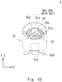
Fig. 10 is a perspective view of the second connector when viewed from the positive side of the z axis.Fig. 11 is an exploded view of the second connector.Fig. 12 is a view of the second connector when viewed from the negative side of the z axis. As shown inFigs. 10 and11 , thesecond connector 5 includes afirst housing 51, aground terminal 52, asecond housing 53, and asignal terminal 54. - The
first housing 51 is an insulating resin molded object, for example. As shown inFigs. 10 and11 , thefirst housing 51 has a substantially cylindrical shape. Thefirst housing 51 has agroove 51a on its inner periphery. As shown inFig. 12 , thegroove 51a extends in the z axis direction, and disposed so as to be opposed in the x axis direction. - Further, as shown in
Fig. 11 , thefirst housing 51 has a hollow 51b on its inner periphery. The hollow 51b extends in the z axis direction, for example, and it has a substantially rectangular shape when viewed from a center axis AX2 of thefirst housing 51 to the outside in the radial direction of thefirst housing 51. As shown inFig. 12 , thehollows 51b are disposed at substantially equal intervals in the circumferential direction of thefirst housing 51. - As shown in
Figs. 11 and12 , thefirst housing 51 has anotch 51c that is open to the negative side of the z axis at its end on the negative side of the z axis. Thenotch 51c has a substantially rectangular shape when viewed from the y axis direction, for example, and thenotches 51c are disposed so as to be opposed in the y axis direction. - As shown in
Figs. 10 and11 , at the end of thefirst housing 51 on the positive side of the z axis, aninclined surface 51d in a conical shape that is inclined to the negative side of the z axis toward the center axis AX2 side of thefirst housing 51 is formed. - The
ground terminal 52 has electrical conductivity, and it is electrically connected to aboard 32 of theimaging unit 3 as shown inFig. 1 . As shown inFig. 10 , theground terminal 52 is inserted into thefirst housing 51. As shown inFig. 11 , theground terminal 52 includes atubular part 52a, a firstcontact spring part 52b, a secondcontact spring part 52c, aleg part 52d, and aninsertion part 52e. - As shown in
Fig. 5 , thetubular part 52a is disposed inside thefirst housing 51. As shown inFig. 11 , for example, thetubular part 52a has a substantially cylindrical shape. The outside diameter of thetubular part 52a is substantially equal to the inside diameter of thefirst housing 51. - In the state where the
ground terminal 52 is inserted into thefirst housing 51, the end of thetubular part 52a on the positive side of the z axis is disposed at substantially the same height as the end of theinclined surface 51d on the inside diameter side in thefirst housing 51 as shown inFig. 10 . - As shown in
Fig. 12 , the firstcontact spring part 52b is disposed inside thegroove 51a of thetubular part 52a. As shown inFig. 11 , the firstcontact spring part 52b is disposed inside afirst opening 52f in thetubular part 52a. The firstcontact spring part 52b has a plate shape, and the end of the firstcontact spring part 52b on the positive side of the z axis is connected to the end of thefirst opening 52f of thetubular part 52a on the positive side of the z axis. - As shown in
Fig. 11 , for example, the firstcontact spring part 52b has aninclined part 52g that is inclined outward in the radial direction of thetubular part 52a toward the negative side of the z axis, and aflat part 52h that extends to the negative side of the z axis from theinclined part 52g. - As shown in
Figs. 11 and12 , the firstcontact spring part 52b is disposed so as to be opposed in the x axis direction, and in the state where theground terminal 52 is inserted into thefirst housing 51, theflat part 52h of the firstcontact spring part 52b is in contact with the bottom surface of thegroove 51a of thefirst housing 51. - As shown in
Fig. 12 , the secondcontact spring part 52c is disposed so as to be opposed to the hollow 51b of thefirst housing 51. As shown inFig. 11 , the secondcontact spring part 52c is disposed inside a second opening 52i in thetubular part 52a. The secondcontact spring part 52c has a plate shape, and the end of the secondcontact spring part 52c on the negative side of the z axis is connected to the end of the second opening 52i of thetubular part 52a on the negative side of the z axis. - As shown in
Fig. 11 , the secondcontact spring part 52c has a corrugated shape when viewed from the circumferential direction of thetubular part 52a. Specifically, the secondcontact spring part 52c includes afirst curve part 52j that projects inward in the radial direction of thetubular part 52a and asecond curve part 52k that is disposed on the negative side of the z axis relative to thefirst curve part 52j and projects outward in the radial direction of thetubular part 52a. - As shown in
Figs. 11 and12 , the secondcontact spring parts 52c are disposed at substantially equal intervals in the circumferential direction of thetubular part 52a, and in the state where theground terminal 52 is inserted into thefirst housing 51, thesecond curve part 52k of the secondcontact spring parts 52c is in contact with the bottom surface of the hollow 51b of thefirst housing 51. - In this manner, the first
contact spring part 52b and the secondcontact spring parts 52c come into contact with the inner periphery of thefirst housing 51, and thereby theground terminal 52 is held by thefirst housing 51. Note that the firstcontact spring part 52b and the secondcontact spring parts 52c can be formed by cutting out and bending thetubular part 52a. - As shown in
Fig. 5 , theleg part 52d is disposed on the negative side of the z axis relative to thefirst housing 51. As shown inFig. 11 , theleg part 52d projects outward in the radial direction of thetubular part 52a from the end of thetubular part 52a on the negative side of the z axis. - As shown in
Fig. 11 , theleg parts 52d are disposed at substantially equal intervals in the circumferential direction of thetubular part 52a. In the state where theground terminal 52 is inserted into thefirst housing 51, theleg part 52d is drawn from the outer periphery of thefirst housing 51 as shown inFig. 12 . - As shown in
Fig. 11 , theinsertion part 52e is disposed inside anotch 52m formed at the end of thetubular part 52a on the negative side of the z axis. Theinsertion part 52e has a plate shape, and the end of theinsertion part 52e on the positive side of the z axis is connected to the end of thenotch 52m of thetubular part 52a on the positive side of the z axis. Theinsertion part 52e has a substantially rectangular shape when viewed from the y axis direction, for example. - As shown in
Fig. 11 , theinsertion part 52e preferably has a first projectingpart 52n that projects outward in the radial direction of thetubular part 52a from theinsertion part 52e. Further, theinsertion part 52e preferably has a second projecting part 52o that projects in the circumferential direction of thetubular part 52a from theinsertion part 52e. - The
second housing 53 is an insulating resin molded object, for example. As shown inFigs. 10 and12 , thesecond housing 53 is inserted into thetubular part 52a of theground terminal 52. As shown inFig. 11 , thesecond housing 53 includes atubular part 53a, aflange part 53b, a projectingpart 53c, and an insert-receivingpart 53d. - As shown in
Fig. 10 , thetubular part 53a is disposed inside thetubular part 52a of theground terminal 52. As shown inFig. 11 , for example, thetubular part 53a has a substantially cylindrical shape. As shown inFig. 12 ,grooves 53e may be disposed at substantially equal intervals in the circumferential direction of thetubular part 53a. - In the state where the
second housing 53 is inserted into thetubular part 52a of theground terminal 52, the end of thetubular part 53a on the positive side of the z axis is disposed at a lower position than the end of theground terminal 52 on the positive side of the z axis as shown inFig. 5 . - As shown in
Fig. 5 , theflange part 53b is disposed inside thetubular part 52a of theground terminal 52. As shown inFig. 11 , theflange part 53b projects outward in the radial direction of thetubular part 53a from the outer periphery of thetubular part 53a. Theflange part 53b has a substantially circular ring shape when viewed from the z axis direction, for example. Theflange part 53b is disposed at the end of thetubular part 53a on the negative side of the z axis. - As shown in
Fig. 12 , at the end of thetubular part 53a and theflange part 53b on the negative side of the z axis, an insert-receivingpart 53f is preferably formed to be continuous with the inside of thetubular part 53a. The insert-receivingpart 53f extends in the x axis direction so as to lie across the inside of thetubular part 53a. The insert-receivingpart 53f has a substantially rectangular shape when viewed from the z axis direction, for example, and the insert-receivingpart 53f is open to the negative side of the z axis. - Further, as shown in
Fig. 12 , a hollow 53g is preferably formed at the end of thetubular part 53a and theflange part 53b on the negative side of the z axis. The hollow 53g extends on the positive side of the y axis from the inside of thetubular part 53a. The hollow 53g has a substantially convex shape that projects on the positive side of the y axis when viewed from the z axis direction, for example, and the hollow 53g is open to the negative side of the z axis. - As shown in
Figs. 10 and12 , the projectingpart 53c passes through thenotch 51c on the negative side of the y axis of thefirst housing 51. As shown inFig. 11 , the projectingpart 53c projects outward in the radial direction of theflange part 53b from the outer periphery of theflange part 53b. The projectingpart 53c is disposed at the end of thetubular part 53a on the negative side of the z axis and opposed in the y axis direction. - As shown in
Figs. 11 and12 , the insert-receivingpart 53d is a penetration part that is formed in the projectingpart 53c on the negative side of the y axis. The insert-receivingpart 53d extends in the z axis direction. As shown inFig. 12 , the insert-receivingpart 53d preferably has a projectingpart 53h that projects from the inner periphery of the insert-receivingpart 53d. In the state where thesecond housing 53 is inserted into theground terminal 52, theinsertion part 52e of theground terminal 52 is inserted into the insert-receivingpart 53d. - In this state, the projecting
part 53h of the insert-receivingpart 53d of thesecond housing 53 presses theinsertion part 52e on the positive side of the y axis through the first projectingpart 52n of theground terminal 52, and theinsertion part 52e of theground terminal 52 is interposed between the projectingpart 53h of the insert-receivingpart 53d of thesecond housing 53 and the end of the inner periphery of the insert-receivingpart 53d on the positive side of the y axis. - Further, the second projecting part 52o of the
insertion part 52e in theground terminal 52 is in strong contact with the inner periphery of the insert-receivingpart 53d of thesecond housing 53. Thesecond housing 53 is thereby held by theground terminal 52. - The
signal terminal 54 has electrical conductivity, and it is inserted into thetubular part 53a of thesecond housing 53 as shown inFig. 12 . As shown inFig. 11 , thesignal terminal 54 includes atubular part 54a, acontact spring part 54b, aleg part 54c, and aninsertion part 54d. - As shown in
Fig. 5 , thetubular part 54a is disposed inside thetubular part 53a of thesecond housing 53. Thetubular part 54a has a substantially cylindrical shape, for example. Thecontact spring part 54b is disposed inside thetubular part 53a of thesecond housing 53. As shown inFig. 11 , thecontact spring parts 54b are disposed at substantially equal intervals in the circumferential direction of thetubular part 54a when viewed from the z axis direction. - As shown in
Fig. 11 , thecontact spring part 54b has a plate shape, and it includes acurve part 54e that projects inward in the radial direction of thetubular part 54a, for example, and aconnection part 54f that extends on the negative side of the z axis from thecurve part 54e. The end of theconnection part 54f on the negative side of the z axis is connected to the end of thetubular part 54a on the positive side of the z axis. Thus, thecontact spring part 54b projects on the positive side of the z axis from thetubular part 54a. - As shown in
Fig. 12 , theleg part 54c is drawn from the inside of thetubular part 53a of thesecond housing 53 to the outside of thefirst housing 51 through the hollow 53g and thenotch 51c of thefirst housing 51 on the positive side of the y axis. As shown inFig. 11 , for example, theleg part 54c is substantially L-shaped when viewed from the x axis direction, and the end of theleg part 54c on the positive side of the z axis is connected to the end of thetubular part 54a on the negative side of the z axis. - As shown in
Fig. 12 , theinsertion part 54d is inserted into the insert-receivingpart 53f of thesecond housing 53. As shown inFig. 11 , theinsertion part 54d projects on the positive side and on the negative side of the x axis from theleg part 54c. Theinsertion part 54d has a substantially rectangular shape when viewed from the y axis direction, for example. Theinsertion part 54d is disposed substantially at the center of the height in the z axis direction of the part of theleg part 54c extending in the z axis direction. - As shown in
Fig. 12 , theinsertion part 54d preferably has a projectingpart 54g that projects on the positive side of the y axis from theinsertion part 54d. In the state where thesignal terminal 54 is inserted into thetubular part 53a of thesecond housing 53, theinsertion part 54d is in strong contact with the periphery of the insert-receivingpart 53f of thesecond housing 53 with the projectingpart 54g of theinsertion part 54d interposed therebetween, and thereby thesignal terminal 54 is held by thesecond housing 53. -
Fig. 13 is a perspective view of a relay connector when viewed from the positive side of the z axis.Fig. 14 is an exploded view of the relay connector.Fig. 15 is a perspective view of the relay connector when viewed from the negative side of the z axis. As shown inFig. 5 , therelay connector 6 electrically connects thefirst connector 4 and thesecond connector 5. As shown inFigs. 13 to 15 , therelay connector 6 includes a housing (holding member) 61, asignal terminal 62, and a ground terminal (first terminal) 63. -
Fig. 16 is a perspective view of the housing of the relay connector when viewed from the negative side of the z axis. Thehousing 61 is an insulating resin molded object, for example. As shown inFigs. 14 and16 , thehousing 61 includes atubular part 61a, a firstspherical part 61b, aflange part 61c, awall part 61d, and a secondspherical part 61e. - As shown in
Fig. 16 , for example, thetubular part 61a has a substantially cylindrical shape. At the end of thetubular part 61a on the negative side of the z axis, an insert-receivingpart 61f is formed to be continuous with the inside of thetubular part 61a. The insert-receivingpart 61f extends in the x axis direction so as to lie across the inside of thetubular part 61a. - As shown in
Fig. 16 , for example, the insert-receivingpart 61f has a substantially rectangular shape when viewed from the z axis direction, and the insert-receivingpart 61f is open to the negative side of the z axis. Note that, on the inner periphery of thetubular part 61a,grooves 61g may be formed at substantially equal intervals in the circumferential direction of thetubular part 61a as shown inFig. 15 . - As shown in
Fig. 14 , the firstspherical part 61b is formed at the end of thetubular part 61a on the positive side of the z axis, and apenetration part 61h is formed at substantially the center of the firstspherical part 61b when viewed from the z axis direction. Thepenetration part 61h is continuous with the inside of thetubular part 61a, and it has a substantially cylindrical shape, for example. - The outside diameter (inside diameter) of the
tubular part 61a and the edge of thepenetration part 61h are arranged in a substantially concentric fashion when viewed from the z axis direction. As shown inFig. 14 , the firstspherical part 61b is convex on the positive side of the z axis. The diameter of the firstspherical part 61b is substantially equal to the diameter of thespherical part 44d of thesecond housing 44 in thefirst connector 4. - As shown in
Fig. 14 , theflange part 61c projects outward in the radial direction of thetubular part 61a from the outer periphery of thetubular part 61a. Theflange part 61c has a substantially rectangular shape when viewed from the z axis direction, for example, and each edge of theflange part 61c curves along the inner peripheral shape of thefirst part 42a of theground terminal 42 in thefirst connector 4. - A circle that is formed by connecting the rim of the
flange part 61c and the edge of thepenetration part 61h of the firstspherical part 61b are arranged in a substantially concentric fashion when viewed from the z axis direction. Theflange part 61c is disposed in the part of thetubular part 61a on the positive side of the z axis. - As shown in
Fig. 16 , at the end of theflange part 61c on the negative side of the z axis, aninclined surface 61i that is inclined outward in the radial direction of thetubular part 61a toward the positive side of the z axis is formed. Theinclined surface 61i is disposed between the edges of theflange part 61c. - As shown in
Fig. 14 , an insert-receivingpart 61j is formed in theflange part 61c. The insert-receivingpart 61j penetrates theflange part 61c in the z axis direction, and it has a substantially rectangular pillar shape when viewed from the z axis direction, for example. - As shown in
Figs. 14 and16 , thewall part 61d extends on the negative side of the z axis from each edge of theflange part 61c and also projects outward in the radial direction of thetubular part 61a from the outer periphery of thetubular part 61a. The side surface of thewall part 61d curves to be continuous with each edge of theflange part 61c when viewed in the z axis direction. - As shown in
Fig. 16 , the secondspherical part 61e is formed at the end of thewall part 61d on the negative side of the z axis. The secondspherical part 61e is convex on the negative side of the z axis. The diameter of the secondspherical part 61e is substantially equal to the diameter of thespherical part 41s of thefirst housing 41 in thefirst connector 4. - The
signal terminal 62 has electrical conductivity, and it is inserted into thetubular part 61a of thehousing 61 as shown inFig. 5 . As shown inFig. 14 , thesignal terminal 62 includes atubular part 62a, acontact spring part 62b, aninsertion part 62c, and apillar part 62d. As shown inFig. 5 , thetubular part 62a is disposed inside thetubular part 61a of thehousing 61. Thetubular part 62a has a substantially cylindrical shape, for example. - As shown in
Fig. 5 , thecontact spring part 62b is disposed inside thetubular part 61a of thehousing 61. As shown inFig. 14 , thecontact spring parts 62b are disposed at substantially equal intervals in the circumferential direction of thetubular part 62a when viewed from the z axis direction. Thecontact spring part 62b has a plate shape, and the end of thecontact spring part 62b on the negative side of the z axis is connected to the end of thetubular part 61a on the positive side of the z axis. - As shown in
Fig. 14 , for example, thecontact spring part 62b has a corrugated shape when viewed from the circumferential direction of thetubular part 62a. Specifically, thecontact spring part 62b includes afirst curve part 62e that projects inward in the radial direction of thetubular part 62a and asecond curve part 62f that is disposed on the negative side of the z axis relative to thefirst curve part 62e and projects outward in the radial direction of thetubular part 62a. - As shown in
Fig. 15 , theinsertion part 62c is inserted into the insert-receivingpart 61f of thehousing 61. As shown inFig. 14 , for example, theinsertion part 62c has a substantially lying H shape when viewed from the y axis direction, and the end of theinsertion part 62c on the positive side of the z axis is connected to the end of thetubular part 62a on the negative side of the z axis. Theinsertion part 62c is disposed on the negative side of the y axis of thetubular part 62a. - In the state where the
insertion part 62c is inserted into the insert-receivingpart 61f of thehousing 61, theinsertion part 62c is in strong contact with the periphery of the insert-receivingpart 61f of thehousing 61, and thereby thesignal terminal 62 is held by thehousing 61. - As shown in
Fig. 5 , thepillar part 62d projects on the negative side of the z axis from thehousing 61. Thepillar part 62d has a substantially cylindrical shape, for example, and the end of thepillar part 62d on the negative side of the z axis is narrowed as shown inFig. 14 . - As shown in
Fig. 14 , thepillar part 62d extends on the negative side of the z axis from theinsertion part 62c. Thepillar part 62d is disposed substantially at the center of the width in the x axis direction of theinsertion part 62c. The outer periphery (inner periphery) of thepillar part 62d and the outer periphery (inner periphery) of thetubular part 62a are arranged in a substantially concentric fashion when viewed from the z axis direction. - The
ground terminal 63 has electrical conductivity, and it surrounds thehousing 61 as shown inFig. 13 . As shown inFig. 14 , theground terminal 63 includes a firsttubular part 63a, a secondtubular part 63b, aconnection part 63c, acontact spring part 63d, and aninsertion part 63e. The firsttubular part 63a has a substantially cylindrical shape, for example. - The second
tubular part 63b is disposed on the positive side of the z axis relative to the firsttubular part 63a, and it has a substantially cylindrical shape, for example. The outside diameter of the secondtubular part 63b is smaller than the outside diameter of the firsttubular part 63a as shown inFig. 14 . - As shown in
Fig. 5 , the inside diameter of the secondtubular part 63b is smaller than the inside diameter of the firsttubular part 63a as shown inFig. 5 . The outer periphery (inner periphery) of the firsttubular part 63a and the outer periphery (inner periphery) of the secondtubular part 63b are arranged in a substantially concentric fashion when viewed from the z axis direction. - As shown in
Fig. 14 , theconnection part 63c connects the firsttubular part 63a and the secondtubular part 63b. Theconnection part 63c has a substantially conical shape that tapers inward in the radial direction of theconnection part 63c toward the positive side of the z axis. Theconnection part 63c may have anopening 63f. - As shown in
Fig. 13 , thecontact spring part 63d covers theinclined surface 61i of thehousing 61, and is disposed on the positive side of the z axis relative to the secondspherical part 61e of thehousing 61. As shown inFig. 14 , thecontact spring parts 63d are disposed at substantially equal intervals in the circumferential direction of the secondtubular part 63b when viewed in the z axis direction. Thecontact spring part 63d has a plate shape, and the end of thecontact spring part 63d on the negative side of the z axis is connected to the end of the secondtubular part 63b on the positive side of the z axis. - As shown in
Fig. 14 , for example, thecontact spring part 63d curves to project outward in the radial direction of the secondtubular part 63b when viewed in the circumferential direction of the secondtubular part 63b. Specifically, thecontact spring part 63d includes acurve part 63g that curves outward in the radial direction of the secondtubular part 63b, and a connection part (inclined part) 63h that connects thecurve part 63g and the secondtubular part 63b and it is inclined outward in the radial direction of the secondtubular part 63b toward the positive side of the z axis. Theconnection part 63h is inclined along theinclined surface 61i of thehousing 61. - The curvature of the lateral surface (i.e., the surface of the second
tubular part 63b on the outer side in the radial direction) of thecurve part 63g of thecontact spring part 63d is preferably greater than the curvature of thespherical part 42c of theground terminal 42 of thefirst connector 4 as shown inFig. 5 . - Further, the lateral surface of the
curve part 63g of thecontact spring part 63d preferably has acontact point 63i that projects outward in the radial direction of the secondtubular part 63b from the lateral surface of thecurve part 63g, as shown inFig. 14 . A projecting surface of thecontact point 63i is spherical, and the curvature of the projecting surface of thecontact point 63i is greater than the curvature of thespherical part 42c of theground terminal 42 of thefirst connector 4. - Furthermore, as shown in
Fig. 5 , the distance between the external end in the radial direction of the secondtubular part 63b in thecontact point 63i and a center line AX3 of the ground terminal 63 (i.e., the distance in the direction orthogonal to the center line AX3) is preferably slightly larger than the radius of thespherical part 42c of theground terminal 42 of thefirst connector 4. - As shown in
Fig. 13 , theinsertion part 63e is inserted into the insert-receivingpart 61j of thehousing 61. As shown inFig. 14 , theinsertion part 63e projects on the positive side of the z axis from the secondtubular part 63b. Theinsertion part 63e is disposed on the negative side of the y axis of the secondtubular part 63b. - As shown in
Fig. 14 , theinsertion part 63e has a plate shape, and it has a substantially rectangular shape when viewed from the y axis direction, for example. Theinsertion part 63e preferably has a projectingpart 63j that projects on the negative side of the y axis from theinsertion part 63e. - In the state where the
insertion part 63e is inserted into the insert-receivingpart 61j of thehousing 61, theinsertion part 63e is in strong contact with the periphery of the insert-receivingpart 61j of thehousing 61 with the projectingpart 63j of theinsertion part 63e interposed therebetween, and thereby theground terminal 63 is held by thehousing 61. The end of theground terminal 63 on the negative side of the z axis is disposed at substantially the same height as the end of thesignal terminal 62 on the negative side of the z axis as shown inFig. 5 . - The flow of electrically connecting the
first connector 4 and therelay connector 6 is described hereinafter.Fig. 17 is a view illustrating the flow of electrically connecting the first connector and the relay connector. The cross-sectional position inFig. 17 corresponds to that inFig. 4 . First, a part of thefirst connector 4 and therelay connector 6 are assembled. - To be specific, the
signal terminal 45 of thefirst connector 4 is inserted into thesecond housing 44 from the positive side of the z axis, and theflange part 45b of thesignal terminal 45 is inserted into thesecond housing 44 until theflange part 45b of thesignal terminal 45 comes into substantial contact with the projectingpart 44b of thesecond housing 44, and thereby thesignal terminal 45 and thesecond housing 44 are fixed to each other. - Next, the
second housing 44 to which thesignal terminal 45 is fixed is inserted into theground terminal 42 from the positive side of the z axis, and theflange part 44c of thesecond housing 44 is inserted into theground terminal 42 until theflange part 44c of thesecond housing 44 comes into substantial contact with the first projectingpart 42d of theground terminal 42, and thereby thesecond housing 44 and theground terminal 42 are fixed to each other. - A part of the
first connector 4 is thereby assembled. In this state, as shown inFig. 2 , a center axis AX1 of theground terminal 42, a center axis AX4 of thesecond housing 44, and a center axis AX5 of thesignal terminal 45 are substantially coaxially arranged. - At the same time, the part of the
relay connector 6 on the positive side of the z axis including theinsertion part 62c of thesignal terminal 62 is inserted into thehousing 61 from the negative side of the z axis, and theinsertion part 62c of thesignal terminal 62 is inserted into the insert-receivingpart 61f of thehousing 61, and thereby thehousing 61 and thesignal terminal 62 are fixed to each other. - In this state, the
contact spring part 62b of thesignal terminal 62 is disposed along the edge of thepenetration part 61h of thehousing 61 when viewed from the z axis direction. Further, thepillar part 62d of thesignal terminal 62 is disposed inside thepenetration part 61h of thehousing 61 when viewed from the z axis direction. - Then, the part of the
housing 61 on the negative side of the z axis is inserted into theground terminal 63 so that thecontact spring part 63d of theground terminal 63 is disposed between thewall parts 61d of thehousing 61, and further theinsertion part 63e of theground terminal 63 is inserted into the insert-receivingpart 61j of thehousing 61, and thereby thehousing 61 and theground terminal 63 are fixed to each other. - The
relay connector 6 is thereby assembled. In this state, as shown inFig. 13 , the center axis AX3 of theground terminal 63, the center axis AX6 of thesignal terminal 62, and the center axis AX7 of thehousing 61 are substantially coaxially arranged. - After that, the
relay connector 6 is inserted into thefirst connector 4. To be specific, therelay connector 6 is inserted through the opening on the positive side of the z axis of thepenetration part 41d of thefirst housing 41 of thefirst connector 4. - Then, the part of the
ground terminal 63 on the negative side of the z axis in therelay connector 6 passes through thepenetration part 41r of the stopper part 41o of thefirst housing 41 in thefirst connector 4, so that the secondspherical part 61e of thehousing 61 of therelay connector 6 comes into substantial spherical contact with thespherical part 41s of thefirst housing 41. In other words, a first spherical contact part 7 (seeFig. 4 ) is formed by thespherical part 41s of thefirst housing 41 and thehousing 61 of therelay connector 6. - The
penetration part 41d of thefirst housing 41 of thefirst connector 4 has a shape to which therelay connector 6 can be inserted from the positive side of the z axis. Further, thepenetration part 41r of thefirst housing 41 of thefirst connector 4 allows therelay connector 6 to rotate at a specified angle with respect to the center C1 of thespherical part 41s (i.e., the first spherical contact part 7) of thefirst housing 41 of thefirst connector 4, as described later, and it has a smaller radius than the distance between the external end in the radial direction of thetubular part 61a in the secondspherical part 61e of thehousing 61 of therelay connector 6 and the center line AX7 of thehousing 61. - The
relay connector 6 thereby catches on the stopper part 41o of thefirst housing 41 of thefirst connector 4, which prevents therelay connector 6 from coming out from thefirst connector 4 to the negative side of the z axis. - Then, the
ground terminal 42 that is fixed to thesignal terminal 45 is inserted through the opening on the positive side of the z axis of thepenetration part 41d of thefirst housing 41 of thefirst connector 4. Then, thefirst part 42a of theground terminal 42 is inserted into theminor diameter part 411 of thesecond part 41k of thepenetration part 41d of thefirst housing 41, and the second projectingpart 42e of thefirst part 42a of theground terminal 42 is inserted into theminor diameter part 411 of thesecond part 41k of thepenetration part 41d of thefirst housing 41 until the end of theground terminal 42 on the negative side of the z axis comes into substantial contact with the stopper part 41o, and thereby thefirst housing 41 and theground terminal 42 are fixed to each other. - In this state, as shown in
Fig. 2 , the center axis AX1 of theground terminal 42, the center axis AX4 of thesecond housing 44, the center axis AX5 of thesignal terminal 45, and the center axis AX8 of thefirst housing 41 are substantially coaxially arranged in thefirst connector 4. - After that, the
pillar part 45a of thesignal terminal 45 of thefirst connector 4 is inserted into thecontact spring part 62b of thesignal terminal 62 of therelay connector 6. Thesignal terminal 45 of thefirst connector 4 and thesignal terminal 62 of therelay connector 6 are thereby electrically connected. - Further, the
contact spring part 63d of theground terminal 63 in therelay connector 6 is inserted into the part inside theground terminal 42 on the negative side of the z axis in thefirst connector 4, and thecontact point 63i of thecontact spring part 63d comes into substantial point contact with thespherical part 42c of theground terminal 42. - A contact part PI (see
Fig. 5 ) is thereby made by thespherical part 42c of theground terminal 42 of thefirst connector 4 and thecontact point 63i of thecontact spring part 63d of theground terminal 63 of therelay connector 6, and theground terminal 42 of thefirst connector 4 and theground terminal 63 of therelay connector 6 are electrically connected. - Since the curvature of the
contact point 63i is greater than the curvature of thespherical part 42c of theground terminal 42 of thefirst connector 4 as described above, thecontact point 63i adequately comes into substantial point contact with thespherical part 42c of theground terminal 42 of thefirst connector 4. - Then, the
spherical part 44d of thesecond housing 44 of thefirst connector 4 comes into substantially spherical contact with the firstspherical part 61b of thehousing 61 of therelay connector 6. In other words, a second spherical contact part 8 (seeFig. 4 ) is formed by thespherical part 44d of thesecond housing 44 of thefirst connector 4 and the firstspherical part 61b of thehousing 61 of therelay connector 6. - In this state, the
housing 61 of therelay connector 6 is interposed between thespherical part 41s of thefirst housing 41 of thefirst connector 4 and thespherical part 44d of thesecond housing 44. Therefore, as shown inFig. 5 , the center C1 of thespherical part 41s of thefirst housing 41 of thefirst connector 4, the center C2 of thespherical part 42c of theground terminal 42, and the center C3 of thespherical part 44d of the second housing 44 (i.e., the second spherical contact part 8) are kept disposed at substantially the same positions. - Thus, the
relay connector 6 is rotatable at a specified angle with respect to the center C1 of thespherical part 41s of thefirst housing 41 of thefirst connector 4. In this state, thecontact point 63i of theground terminal 63 of therelay connector 6, i.e., the contact part PI, is disposed substantially on the diameter of thespherical part 41s of thefirst housing 41. - After that, the
first potting 43 is applied to thestep part 42f of theground terminal 42 of thefirst connector 4, and also thesecond potting 46 is applied to the end of thesecond housing 44 on the positive side of the z axis in thefirst connector 4. Therelay connector 6 is thereby inserted into thefirst connector 4, and an electrical connection is established between them. In other words, the floatingconnector 11 is thereby assembled. - A process of assembling the
second connector 5 is described hereinafter. First, the part of thesignal terminal 54 on the positive side of the z axis including theinsertion part 54d is inserted into thesecond housing 53 from the negative side of the z axis, and theinsertion part 54d of thesignal terminal 54 is inserted into the insert-receivingpart 53f of thesecond housing 53, and thereby thesecond housing 53 and thesignal terminal 54 are fixed to each other. - At this time, the
contact spring part 54b of thesignal terminal 54 is disposed along the opening of thetubular part 53a of the second housing 53o on the positive side of the z axis when viewed from the z axis direction. Further, theleg part 54c of thesignal terminal 54 is accommodated in the hollow 53g of thesecond housing 53. - Next, the
tubular part 52a of theground terminal 52 is inserted into thefirst housing 51 from the negative side of the z axis, and theflat part 52h of the firstcontact spring part 52b of theground terminal 52 is brought into contact with the bottom surface of thegroove 51a of thefirst housing 51, and also thesecond curve part 52k of the secondcontact spring part 52c is brought into contact with the bottom surface of the hollow 51b of thefirst housing 51, so that thefirst housing 51 and theground terminal 52 are fixed to each other. - At this time, when viewed from the y axis direction, the
insertion part 52e of theground terminal 52 is disposed at thenotch 51c on the negative side of the y axis of thefirst housing 51. Further, theleg part 52d of theground terminal 52 projects outward in the radial direction of thefirst housing 51 from thefirst housing 51. - Then, the
tubular part 53a of thesecond housing 53 fixed to thesignal terminal 54 is inserted from the negative side of the z axis into thetubular part 52a of theground terminal 52 fixed to thefirst housing 51, and theinsertion part 52e of theground terminal 52 is inserted into the insert-receivingpart 53d of thesecond housing 53. - The
first housing 51, theground terminal 52, thesecond housing 53, and thesignal terminal 54 are thereby integrally assembled. In this state, theleg part 54c of thesignal terminal 54 projects outward in the radial direction of thefirst housing 51 from thenotch 51c of thefirst housing 51 on the positive side of the y axis. - In the
second connector 5, as shown inFig. 10 , the center axis AX2 of thefirst housing 51, a center axis AX9 of theground terminal 52, a center axis AX10 of thesecond housing 53, and a center axis AX11 of thesignal terminal 54 are substantially coaxially arranged. - The flow of electrically connecting the
output connector 2 and theimaging unit 3 by using the floatingconnector assembly 1 according to this embodiment is described hereinafter. As shown inFig. 1 , for example, theoutput connector 2 has a structure in which theground terminal 22 and thesignal terminal 23 are accommodated in thehousing 21. Theground terminal 42 of thefirst connector 4 is electrically connected to theground terminal 22 of theoutput connector 2, and thesignal terminal 45 of thefirst connector 4 is electrically connected to thesignal terminal 23. - In this state, the end of the
housing 21 of theoutput connector 2 on the negative side of the z axis is inserted into the second insert-receivingpart 41c of thefirst housing 41 of thefirst connector 4, and theengagement part 21a of thehousing 21 of theoutput connector 2 is engaged with the engaged part 41i of thefirst housing 41. Theoutput connector 2 is thereby reliably fixed to thefirst connector 4. - As shown in
Fig. 1 , for example, theimaging unit 3 has a structure in which theboard 32 on which an imaging element is mounted is accommodated in thehousing 31. Theleg part 52d of theground terminal 52 of thesecond connector 5 and theleg part 54c of thesignal terminal 54 are electrically connected to theboard 32 of theimaging unit 3. - Next, the first
tubular part 63a of theground terminal 63 of therelay connector 6 is inserted into thetubular part 52a of theground terminal 52 of thesecond connector 5 from the positive side of the z axis, and thereby the secondcontact spring part 52c of theground terminal 52 of thesecond connector 5 is brought into contact with the outer periphery of the firsttubular part 63a of theground terminal 63 of therelay connector 6, so that theground terminal 52 of thesecond connector 5 and theground terminal 63 of therelay connector 6 are electrically connected. - At the same time, the
pillar part 62d of thesignal terminal 62 of therelay connector 6 is inserted into thecontact spring part 54b of thesignal terminal 54 of thesecond connector 5 from the positive side of the z axis, so that thesignal terminal 54 of thesecond connector 5 and thesignal terminal 62 of therelay connector 6 are electrically connected. Theoutput connector 2 and theimaging unit 3 are thereby electrically connected through thefirst connector 4, thesecond connector 5, and therelay connector 6. - In this state, the end of the
housing 31 of theimaging unit 3 on the positive side of the z axis is inserted into the first insert-receivingpart 41b of thefirst housing 41 of thefirst connector 4. Theoutput connector 2 and theimaging unit 3 are thereby fixed to each other with thefirst housing 41 of thefirst connector 4 interposed therebetween. - A connection state of the
output connector 2 and theimaging unit 3 in the case where a connection axis AX12 between theoutput connector 2 and thefirst connector 4 and a connection axis AX13 between theimaging unit 3 and thesecond connector 5 are out of alignment is described hereinafter. -
Fig. 18 is a cross-sectional view showing the connection state of the output connector and the imaging unit when the connection axis between the output connector and the first connector and the connection axis between the imaging unit and the second connector are out of alignment.Fig. 19 is an enlarged view of a part XIX shown inFig. 18 . Note that the cross-sectional position inFigs. 18 and19 corresponds to that inFig. 4 . - As described above, the center C1 of the
spherical part 41s of thefirst housing 41 of thefirst connector 4, the center C2 of thespherical part 42c of theground terminal 42, and the center C3 of thespherical part 44d of thesecond housing 44 are disposed at substantially the same positions. Thecontact point 63i of theground terminal 63 of therelay connector 6 is disposed substantially on the diameter of thespherical part 41s of thefirst housing 41. - Therefore, the distance between each
contact point 63i of theground terminal 63 of therelay connector 6 and the center C1 of thespherical part 41s of thefirst housing 41 of thefirst connector 4 does not substantially change, and when, as shown inFigs. 18 and19 , the connection axis AX12 between theoutput connector 2 and thefirst connector 4 and the connection axis AX13 between theimaging unit 3 and thesecond connector 5 are out of alignment, therelay connector 6 rotates with respect to the center C1. - At this time, the
contact spring part 62b of thesignal terminal 62 of therelay connector 6, and the secondcontact spring part 52c of theground terminal 52 and thecontact spring part 54b of thesignal terminal 54 in thesecond connector 5 change in shape so as not to inhibit the rotation of therelay connector 6. - As described above, in the floating
connector assembly 1 and the floatingconnector 11 according to this embodiment, the secondspherical part 61e of thehousing 61 of therelay connector 6 catches on the stopper part 41o of thefirst housing 41 of thefirst connector 4. - Thus, the floating
connector assembly 1 and the floatingconnector 11 according to this embodiment prevent therelay connector 6 from coming out of thefirst connector 4 when transporting therelay connector 6 fixed to thefirst connector 4, for example. Therefore, the floatingconnector assembly 1 and the floatingconnector 11 according to this embodiment reduce loss or damage of therelay connector 6 during transportation, for example. - In the floating
connector assembly 1 and the floatingconnector 11 according to this embodiment, when the connection axis AX12 between theoutput connector 2 and thefirst connector 4 and the connection axis AX13 between theimaging unit 3 and thesecond connector 5 are out of alignment, therelay connector 6 rotates with respect to the center C1 without a substantial change in the distance between eachcontact point 63i of theground terminal 63 of therelay connector 6 and the center C1 of thespherical part 41s of thefirst housing 41 of thefirst connector 4. Therefore, in the floatingconnector assembly 1 and the floatingconnector 11 according to this embodiment, contact pressures of eachcontact point 63i of theground terminal 63 of therelay connector 6 on thespherical part 41s of thefirst housing 41 of thefirst connector 4 are substantially the same, and therefore the stability of electrical connection is maintained. - Further, in the floating
connector assembly 1 and the floatingconnector 11 according to this embodiment, eachcontact point 63i of theground terminal 63 of therelay connector 6 is inscribed in thespherical part 41s of thefirst housing 41 of thefirst connector 4. Therefore, an increase in the size of therelay connector 6 is minimized compared with the case where the contact spring part of theground terminal 63 of therelay connector 6 circumscribes the spherical part formed on the outer periphery of thefirst housing 41 of thefirst connector 4, which achieves size reduction of the floatingconnector assembly 1 and the floatingconnector 11. - In the floating
connector assembly 1 and the floatingconnector 11 according to this embodiment, thehousing 61 of therelay connector 6 is interposed between thefirst housing 41 and thesecond housing 44 of thefirst connector 4 so that the secondspherical part 61e of thehousing 61 of therelay connector 6 is in substantial spherical contact with thespherical part 41s of thefirst housing 41 of thefirst connector 4, and the firstspherical part 61b of therelay connector 6 is in substantial spherical contact with thespherical part 44d of thesecond housing 44 of thefirst connector 4. - Therefore, the floating
connector assembly 1 and the floatingconnector 11 according to this embodiment allow maintaining the state where the center C1 of thespherical part 41s of thefirst housing 41 of thefirst connector 4, the center C2 of thespherical part 42c of theground terminal 42, and the center C3 of thespherical part 44d of thesecond housing 44 are disposed at substantially the same positions. Further, the floatingconnector assembly 1 and the floatingconnector 11 according to this embodiment allow maintaining the state where thecontact point 63i of theground terminal 63 of therelay connector 6 is disposed substantially on the diameter of thespherical part 41s of thefirst housing 41. - Therefore, in the floating
connector assembly 1 and the floatingconnector 11 according to this embodiment, therelay connector 6 appropriately rotates with respect to the center C1 without a substantial change in the distance between eachcontact point 63i of theground terminal 63 of therelay connector 6 and the center C1 of thespherical part 41s of thefirst housing 41 of thefirst connector 4. - The present disclosure is not limited to the above-described embodiment and can be modified as appropriate without departing from the spirit and scope of the present disclosure.
- For example, the floating
connector assembly 1 and the floatingconnector 11 according to this embodiment may have any structure as long as therelay connector 6 is not removed from thefirst housing 41 of thefirst connector 4, and therelay connector 6 is insertable from the part of thefirst housing 41 on the positive side of the z axis. Therefore, therelay connector 6 is not necessarily rotatable, and the shape of the stopper part 41o is also not limited to the above example. - For example, the shapes of the signal terminal and the ground terminal of each connector are shown merely as typical examples, and the shapes are not particularly limited as long as the signal terminal and the ground terminal of the
first connector 4 and the signal terminal and the ground terminal of thesecond connector 5 are electrically connectable through the signal terminal and the ground terminal of therelay connector 6. - For example, the
relay connector 6 is not necessarily interposed between thefirst housing 41 and thesecond housing 44 of thefirst connector 4. - From the disclosure thus described, it will be obvious that the embodiments of the disclosure may be varied in many ways. Such variations are not to be regarded as a departure from the spirit and scope of the disclosure, and all such modifications as would be obvious to one skilled in the art are intended for inclusion within the scope of the following claims.
Claims (7)
- A floating connector constituting a part of a floating connector assembly including a first connector electrically connected to first equipment, a second connector electrically connected to second equipment, and a relay connector inserted into the first connector and also inserted into the second connector to electrically connect the first connector and the second connector, whereinthe floating connector includes the relay connector and the first connector,the relay connector includes a first terminal and a holding member configured to hold the first terminal, andthe first connector includes a second terminal, a housing configured to accommodate the second terminal and accommodate at least part of the holding member in a state where the relay connector and the first connector are electrically connected, an opening where the relay connector is insertable and formed in a second part in an opposite side to a first part disposed in the housing on the second connector side in the state where the first connector and the second connector are electrically connected through the relay connector, and a stopper part formed in the first part of the housing so as to prevent the holding member from coming out of the first part of the housing in a state where the housing accommodates at least part of the holding member.
- The floating connector according to Claim 1, whereinthe first terminal includes a plurality of contact spring parts arranged at intervals in a circumferential direction of the first terminal,the second terminal includes a tubular part where a spherical part is formed,the plurality of contact spring parts come into contact with the spherical part of the second terminal in the state where the relay connector and the first connector are electrically connected, andwhen the relay connector rotates with respect to the first connector, a distance from a center of the spherical part to a contact part between each of the contact spring parts and the spherical part is the same.
- The floating connector according to Claim 2, wherein the contact spring part of the first terminal comes into contact with the spherical part formed in an inner peripheral part of the second terminal in a state where the contact spring part is disposed inside the second terminal.
- The floating connector according to Claim 2 or 3, wherein the stopper part and the holding member are in spherical contact, and a center of a spherical contact part between the stopper part and the holding member coincides with a center of the spherical part.
- The floating connector according to any one of Claims 2 to 4, whereinthe first connector includes a retaining member configured to interpose the holding member between the stopper part and the retaining member, andthe retaining member blocks a part of the opening of the housing.
- The floating connector according to Claim 5, wherein the retaining member and the holding member are in spherical contact, and a center of a spherical contact part between the retaining member and the holding member coincides with a center of the spherical part.
- A floating connector assembly comprising:the floating connector according to any one of Claims 1 to 6; andthe second connector.
Applications Claiming Priority (1)
| Application Number | Priority Date | Filing Date | Title |
|---|---|---|---|
| JP2021198255A JP2023084215A (en) | 2021-12-07 | 2021-12-07 | Floating connector and floating connector assembly |
Publications (2)
| Publication Number | Publication Date |
|---|---|
| EP4195424A1 true EP4195424A1 (en) | 2023-06-14 |
| EP4195424B1 EP4195424B1 (en) | 2024-03-20 |
Family
ID=84044734
Family Applications (1)
| Application Number | Title | Priority Date | Filing Date |
|---|---|---|---|
| EP22204379.6A Active EP4195424B1 (en) | 2021-12-07 | 2022-10-28 | Floating connector and floating connector assembly |
Country Status (4)
| Country | Link |
|---|---|
| US (1) | US20230178934A1 (en) |
| EP (1) | EP4195424B1 (en) |
| JP (1) | JP2023084215A (en) |
| CN (1) | CN116315915A (en) |
Citations (6)
| Publication number | Priority date | Publication date | Assignee | Title |
|---|---|---|---|---|
| US4925403A (en) * | 1988-10-11 | 1990-05-15 | Gilbert Engineering Company, Inc. | Coaxial transmission medium connector |
| JP2006134899A (en) | 2002-11-28 | 2006-05-25 | Toray Eng Co Ltd | Bonding method and bonder |
| FR2990069A1 (en) * | 2012-04-26 | 2013-11-01 | Radiall Sa | Connector assembly for connecting two printed circuit boards in e.g. space field, has connection including rigid body, and set of elastic contacts of masses is adapted to be in support against interior of rigid body of connection |
| CN108023245A (en) * | 2017-12-15 | 2018-05-11 | 谈振新 | It is adapted to blind with allowing to insert inclined component of RF coaxial connector |
| US10916902B2 (en) * | 2018-09-14 | 2021-02-09 | Hirose Electric Co., Ltd. | Coaxial connector assembly |
| EP3819993A1 (en) * | 2019-11-08 | 2021-05-12 | Gigalane Co. Ltd | Connector having joint with limited range of motion |
-
2021
- 2021-12-07 JP JP2021198255A patent/JP2023084215A/en active Pending
-
2022
- 2022-09-20 US US17/933,548 patent/US20230178934A1/en active Pending
- 2022-10-11 CN CN202211240101.7A patent/CN116315915A/en active Pending
- 2022-10-28 EP EP22204379.6A patent/EP4195424B1/en active Active
Patent Citations (6)
| Publication number | Priority date | Publication date | Assignee | Title |
|---|---|---|---|---|
| US4925403A (en) * | 1988-10-11 | 1990-05-15 | Gilbert Engineering Company, Inc. | Coaxial transmission medium connector |
| JP2006134899A (en) | 2002-11-28 | 2006-05-25 | Toray Eng Co Ltd | Bonding method and bonder |
| FR2990069A1 (en) * | 2012-04-26 | 2013-11-01 | Radiall Sa | Connector assembly for connecting two printed circuit boards in e.g. space field, has connection including rigid body, and set of elastic contacts of masses is adapted to be in support against interior of rigid body of connection |
| CN108023245A (en) * | 2017-12-15 | 2018-05-11 | 谈振新 | It is adapted to blind with allowing to insert inclined component of RF coaxial connector |
| US10916902B2 (en) * | 2018-09-14 | 2021-02-09 | Hirose Electric Co., Ltd. | Coaxial connector assembly |
| EP3819993A1 (en) * | 2019-11-08 | 2021-05-12 | Gigalane Co. Ltd | Connector having joint with limited range of motion |
Also Published As
| Publication number | Publication date |
|---|---|
| US20230178934A1 (en) | 2023-06-08 |
| CN116315915A (en) | 2023-06-23 |
| EP4195424B1 (en) | 2024-03-20 |
| JP2023084215A (en) | 2023-06-19 |
Similar Documents
| Publication | Publication Date | Title |
|---|---|---|
| US11549533B2 (en) | Pin and grommet fastener accommodating two directional offset and related methods | |
| EP3620666A1 (en) | Sealing pin and grommet fastener accommodating two directional offset | |
| US20040107533A1 (en) | Waterproof Grommet | |
| US6913486B2 (en) | Waterproof electrical connector | |
| US20090065235A1 (en) | Grommet | |
| KR20000017295A (en) | Storage container for precision substrates | |
| KR20140054205A (en) | Wafer carrier | |
| CN108258535B (en) | Connector with a locking member | |
| EP4195424A1 (en) | Floating connector and floating connector assembly | |
| US20190348774A1 (en) | Female connector and fitting connector | |
| EP0740368A2 (en) | Tubular supporting structure | |
| EP4195423B1 (en) | Floating connector and floating connector assembly | |
| JP2009512990A (en) | Protection cap and connector / protection cap combination | |
| US6666701B1 (en) | Bayonet-type electrical connector assembly | |
| JPH11237527A (en) | Optical connector | |
| US20210399442A1 (en) | Connector | |
| EP1206014B1 (en) | Panel attachment configuration for a connector | |
| JP2023029620A (en) | connector device | |
| JP3909417B2 (en) | Waterproof stopper for waterproof connector | |
| US20210184440A1 (en) | Supporting Element | |
| US6821148B2 (en) | Plug part having a multipole seal manufactured from gel or silicon | |
| EP4125154B1 (en) | Connector | |
| US20050122275A1 (en) | Structure for mounting antenna | |
| US20210249815A1 (en) | Lever type connector | |
| CN112805895A (en) | Mounting member |
Legal Events
| Date | Code | Title | Description |
|---|---|---|---|
| PUAI | Public reference made under article 153(3) epc to a published international application that has entered the european phase |
Free format text: ORIGINAL CODE: 0009012 |
|
| STAA | Information on the status of an ep patent application or granted ep patent |
Free format text: STATUS: EXAMINATION IS IN PROGRESS |
|
| 17P | Request for examination filed |
Effective date: 20221107 |
|
| AK | Designated contracting states |
Kind code of ref document: A1 Designated state(s): AL AT BE BG CH CY CZ DE DK EE ES FI FR GB GR HR HU IE IS IT LI LT LU LV MC ME MK MT NL NO PL PT RO RS SE SI SK SM TR |
|
| GRAP | Despatch of communication of intention to grant a patent |
Free format text: ORIGINAL CODE: EPIDOSNIGR1 |
|
| STAA | Information on the status of an ep patent application or granted ep patent |
Free format text: STATUS: GRANT OF PATENT IS INTENDED |
|
| RIC1 | Information provided on ipc code assigned before grant |
Ipc: H01R 12/91 20110101ALN20231016BHEP Ipc: H01R 31/06 20060101ALN20231016BHEP Ipc: H01R 103/00 20060101ALN20231016BHEP Ipc: H01R 24/40 20110101ALI20231016BHEP Ipc: H01R 13/631 20060101AFI20231016BHEP |
|
| RBV | Designated contracting states (corrected) |
Designated state(s): AL AT BE BG CH CY CZ DE DK EE ES FI FR GB GR HR HU IE IS IT LI LT LU LV MC ME MK MT NL NO PL PT RO RS SE SI SK SM TR |
|
| INTG | Intention to grant announced |
Effective date: 20231113 |
|
| GRAS | Grant fee paid |
Free format text: ORIGINAL CODE: EPIDOSNIGR3 |
|
| GRAA | (expected) grant |
Free format text: ORIGINAL CODE: 0009210 |
|
| STAA | Information on the status of an ep patent application or granted ep patent |
Free format text: STATUS: THE PATENT HAS BEEN GRANTED |
|
| AK | Designated contracting states |
Kind code of ref document: B1 Designated state(s): AL AT BE BG CH CY CZ DE DK EE ES FI FR GB GR HR HU IE IS IT LI LT LU LV MC ME MK MT NL NO PL PT RO RS SE SI SK SM TR |
|
| REG | Reference to a national code |
Ref country code: GB Ref legal event code: FG4D |
|
| REG | Reference to a national code |
Ref country code: CH Ref legal event code: EP |
|
| REG | Reference to a national code |
Ref country code: DE Ref legal event code: R096 Ref document number: 602022002457 Country of ref document: DE |