EP4195232A2 - High voltage high current fuse with arc interrupter - Google Patents
High voltage high current fuse with arc interrupter Download PDFInfo
- Publication number
- EP4195232A2 EP4195232A2 EP22210559.5A EP22210559A EP4195232A2 EP 4195232 A2 EP4195232 A2 EP 4195232A2 EP 22210559 A EP22210559 A EP 22210559A EP 4195232 A2 EP4195232 A2 EP 4195232A2
- Authority
- EP
- European Patent Office
- Prior art keywords
- bus bar
- housing
- fuse
- recited
- Prior art date
- Legal status (The legal status is an assumption and is not a legal conclusion. Google has not performed a legal analysis and makes no representation as to the accuracy of the status listed.)
- Granted
Links
Images

Classifications
-
- H—ELECTRICITY
- H01—ELECTRIC ELEMENTS
- H01H—ELECTRIC SWITCHES; RELAYS; SELECTORS; EMERGENCY PROTECTIVE DEVICES
- H01H85/00—Protective devices in which the current flows through a part of fusible material and this current is interrupted by displacement of the fusible material when this current becomes excessive
- H01H85/02—Details
- H01H85/0241—Structural association of a fuse and another component or apparatus
-
- H—ELECTRICITY
- H01—ELECTRIC ELEMENTS
- H01H—ELECTRIC SWITCHES; RELAYS; SELECTORS; EMERGENCY PROTECTIVE DEVICES
- H01H85/00—Protective devices in which the current flows through a part of fusible material and this current is interrupted by displacement of the fusible material when this current becomes excessive
- H01H85/02—Details
- H01H85/04—Fuses, i.e. expendable parts of the protective device, e.g. cartridges
- H01H85/05—Component parts thereof
- H01H85/055—Fusible members
- H01H85/06—Fusible members characterised by the fusible material
-
- H—ELECTRICITY
- H01—ELECTRIC ELEMENTS
- H01H—ELECTRIC SWITCHES; RELAYS; SELECTORS; EMERGENCY PROTECTIVE DEVICES
- H01H37/00—Thermally-actuated switches
- H01H37/74—Switches in which only the opening movement or only the closing movement of a contact is effected by heating or cooling
- H01H37/76—Contact member actuated by melting of fusible material, actuated due to burning of combustible material or due to explosion of explosive material
- H01H37/761—Contact member actuated by melting of fusible material, actuated due to burning of combustible material or due to explosion of explosive material with a fusible element forming part of the switched circuit
-
- H—ELECTRICITY
- H01—ELECTRIC ELEMENTS
- H01H—ELECTRIC SWITCHES; RELAYS; SELECTORS; EMERGENCY PROTECTIVE DEVICES
- H01H85/00—Protective devices in which the current flows through a part of fusible material and this current is interrupted by displacement of the fusible material when this current becomes excessive
- H01H85/02—Details
- H01H85/04—Fuses, i.e. expendable parts of the protective device, e.g. cartridges
- H01H85/05—Component parts thereof
- H01H85/055—Fusible members
- H01H85/08—Fusible members characterised by the shape or form of the fusible member
- H01H85/10—Fusible members characterised by the shape or form of the fusible member with constriction for localised fusing
-
- H—ELECTRICITY
- H01—ELECTRIC ELEMENTS
- H01H—ELECTRIC SWITCHES; RELAYS; SELECTORS; EMERGENCY PROTECTIVE DEVICES
- H01H85/00—Protective devices in which the current flows through a part of fusible material and this current is interrupted by displacement of the fusible material when this current becomes excessive
- H01H85/02—Details
- H01H85/04—Fuses, i.e. expendable parts of the protective device, e.g. cartridges
- H01H85/05—Component parts thereof
- H01H85/165—Casings
-
- H—ELECTRICITY
- H01—ELECTRIC ELEMENTS
- H01H—ELECTRIC SWITCHES; RELAYS; SELECTORS; EMERGENCY PROTECTIVE DEVICES
- H01H85/00—Protective devices in which the current flows through a part of fusible material and this current is interrupted by displacement of the fusible material when this current becomes excessive
- H01H85/02—Details
- H01H85/04—Fuses, i.e. expendable parts of the protective device, e.g. cartridges
- H01H85/05—Component parts thereof
- H01H85/165—Casings
- H01H85/175—Casings characterised by the casing shape or form
-
- H—ELECTRICITY
- H01—ELECTRIC ELEMENTS
- H01H—ELECTRIC SWITCHES; RELAYS; SELECTORS; EMERGENCY PROTECTIVE DEVICES
- H01H85/00—Protective devices in which the current flows through a part of fusible material and this current is interrupted by displacement of the fusible material when this current becomes excessive
- H01H85/02—Details
- H01H85/20—Bases for supporting the fuse; Separate parts thereof
- H01H85/205—Electric connections to contacts on the base
-
- H—ELECTRICITY
- H01—ELECTRIC ELEMENTS
- H01H—ELECTRIC SWITCHES; RELAYS; SELECTORS; EMERGENCY PROTECTIVE DEVICES
- H01H85/00—Protective devices in which the current flows through a part of fusible material and this current is interrupted by displacement of the fusible material when this current becomes excessive
- H01H85/02—Details
- H01H85/38—Means for extinguishing or suppressing arc
-
- H—ELECTRICITY
- H01—ELECTRIC ELEMENTS
- H01H—ELECTRIC SWITCHES; RELAYS; SELECTORS; EMERGENCY PROTECTIVE DEVICES
- H01H37/00—Thermally-actuated switches
- H01H37/74—Switches in which only the opening movement or only the closing movement of a contact is effected by heating or cooling
- H01H37/76—Contact member actuated by melting of fusible material, actuated due to burning of combustible material or due to explosion of explosive material
- H01H37/761—Contact member actuated by melting of fusible material, actuated due to burning of combustible material or due to explosion of explosive material with a fusible element forming part of the switched circuit
- H01H2037/762—Contact member actuated by melting of fusible material, actuated due to burning of combustible material or due to explosion of explosive material with a fusible element forming part of the switched circuit using a spring for opening the circuit when the fusible element melts
-
- H—ELECTRICITY
- H01—ELECTRIC ELEMENTS
- H01H—ELECTRIC SWITCHES; RELAYS; SELECTORS; EMERGENCY PROTECTIVE DEVICES
- H01H85/00—Protective devices in which the current flows through a part of fusible material and this current is interrupted by displacement of the fusible material when this current becomes excessive
- H01H85/02—Details
- H01H85/38—Means for extinguishing or suppressing arc
- H01H2085/381—Means for extinguishing or suppressing arc with insulating body insertable between the end contacts of the fusible element
-
- H—ELECTRICITY
- H01—ELECTRIC ELEMENTS
- H01H—ELECTRIC SWITCHES; RELAYS; SELECTORS; EMERGENCY PROTECTIVE DEVICES
- H01H85/00—Protective devices in which the current flows through a part of fusible material and this current is interrupted by displacement of the fusible material when this current becomes excessive
- H01H85/02—Details
- H01H85/04—Fuses, i.e. expendable parts of the protective device, e.g. cartridges
- H01H85/05—Component parts thereof
- H01H85/143—Electrical contacts; Fastening fusible members to such contacts
-
- H—ELECTRICITY
- H01—ELECTRIC ELEMENTS
- H01H—ELECTRIC SWITCHES; RELAYS; SELECTORS; EMERGENCY PROTECTIVE DEVICES
- H01H85/00—Protective devices in which the current flows through a part of fusible material and this current is interrupted by displacement of the fusible material when this current becomes excessive
- H01H85/02—Details
- H01H85/36—Means for applying mechanical tension to fusible member
-
- H—ELECTRICITY
- H01—ELECTRIC ELEMENTS
- H01H—ELECTRIC SWITCHES; RELAYS; SELECTORS; EMERGENCY PROTECTIVE DEVICES
- H01H9/00—Details of switching devices, not covered by groups H01H1/00 - H01H7/00
- H01H9/30—Means for extinguishing or preventing arc between current-carrying parts
- H01H9/32—Insulating body insertable between contacts
Definitions
- the present disclosure relates to electrical circuit protection, and more particularly to fuses for high voltage and/or high current such as in electric, hybrid or more-electric aerospace applications.
- a fuse includes a housing.
- a bus bar extends through the housing.
- An arc interrupter is positioned inside the housing.
- a biasing element is compressed between the housing and the arc interrupter to bias the arc interrupter toward the bus bar to separate two portions of the bus bar during circuit interruption to mitigate arcing from one portion of the bus bar to the other portion of the bus bar.
- the bus bar includes a pocket defined therein wherein the bus bar is of a first material, and wherein a second material is seated within the pocket.
- the housing can be ceramic or can be coated inside with a ceramic material.
- the pocket and second material can be within the housing.
- the first material can have a higher melting temperature than the second material. Both the first material and the second material can be electrically conductive.
- a reservoir can be defined in the housing below the pocket in the bus bar with respect to gravity for receiving the second material in molten form during circuit interrupt.
- a flow diverter can extend upward from the reservoir wherein the flow diverter is configured to divert molten material away from a center of the housing.
- the flow diverter, biasing member, and arc interrupter can be configured to drive the arc interrupter into the flow diverter during circuit interrupt to form a barrier between the two portions of the bus bar.
- Lateral edges of the arc interrupter can be toleranced close to lateral walls of the housing to reduce or prevent flow of particles around the arc interrupter.
- Lateral edges of the arc interrupter can include laterally extending flanges, giving the arc interrupter an H-shaped cross-sectional profile. The laterally extending flanges can form a tortuous path with the housing to reduce or prevent flow of particles around the arc interrupter.
- a first portion of the bus bar outside the housing can include at least one fastener opening therethrough for connecting the bus bar to a first contact in an electrical line.
- a second portion of the bus bar outside the housing opposite the first portion can include at least one fastener opening therethrough for connecting the bus bar to a second contact in an electrical line in series with the first contact through the bus bar.
- a fuse in another aspect, includes a fuse housing and a bus bar extending through the housing.
- the bus bar includes a pocket defined therein.
- the bus bar is of a first material, wherein a second material is seated within the pocket.
- the pocket and second material can be within the housing.
- the first material can have a higher melting temperature than the second material. Both the first material and the second material can be electrically conductive.
- a reservoir can be defined in the housing below the pocket in the bus bar with respect to gravity for receiving the second material in molten form during circuit interrupt.
- a flow diverter can extend upward from the reservoir wherein the flow diverter is configured to divert molten material away from a center of the housing.
- the housing can be coated inside with a ceramic material.
- a first portion of the bus bar outside the housing can include at least one fastener opening therethrough for connecting the bus bar to a first contact in an electrical line.
- a second portion of the bus bar outside the housing opposite the first portion can include at least one fastener opening therethrough for connecting the bus bar to a second contact in an electrical line in series with the first contact through the bus bar.
- FIG. 1 a partial view of an embodiment of a fuse in accordance with the disclosure is shown in Fig. 1 and is designated generally by reference character 100.
- FIGs. 2-5 Other embodiments of systems in accordance with the disclosure, or aspects thereof, are provided in Figs. 2-5 , as will be described.
- the systems and methods described herein can be used to mitigate and/or eliminate arcing through plasma and/or particles in a fuse housing after the fuse's bus bar has melted to interrupt a faulted circuit.
- the fuse 100 includes a housing 102 manufactured of a ceramic material or any nonconductive material coated inside with a ceramic material 104 and enclosed by a cap 106.
- a bus bar 108 extends through the housing 102.
- An arc interrupter 110 is positioned inside the housing 102.
- a biasing element 112, such as a spring or the like, is compressed between the cap 106 of the housing 102 and the arc interrupter 110 to bias the arc interrupter 110 toward and against the bus bar 108
- the bus bar includes a pocket 114 defined therein.
- the wherein the bus bar 108 is of a first material, and a second material 116 is seated within the pocket 114. Both the pocket 114 and second material 116 are within the housing 102.
- the first material i.e. the bus bar 108, has a higher melting temperature than the second material 116. Both the first material and the second material 116 are electrically conductive.
- a reservoir 118 is defined in the housing 102 below the pocket 114 in the bus bar 108 with respect to gravity, i.e. as oriented in Figs. 1-3 , for receiving the second material 116 in molten form during circuit interrupt.
- the second material 116 melts before the first material of the bus bar 108, as shown in Fig 2 .
- the reduction in electrical cross-sectional area of the bus bar 108 intensifies the heating in the narrow portion 120 of the bus bar 108 proximate the pocket 114, helping insure the narrow portion 120 is next to melt.
- a flow diverter 122 extends upward from the reservoir 118.
- the flow diverter 122 is configured to divert molten material (the second material 116 and material from the narrow portion 120 of the bus bar 108) away from a center of the housing 102.
- the flow diverter 122, biasing member 112, and arc interrupter 110 are configured to drive the arc interrupter 110 into, i.e., against, the flow diverter 122 during circuit interrupt as the narrow portion 120 of the bus bar 108 melts/ablates away.
- the movement of the arc interrupter 110 is from the position shown in Fig. 2 to the position shown in Fig. 3 .
- This separation mitigates and/or eliminates arcing from one portion 124, 126 of the bus bar 108 to the other portion 124, 126 of the bus bar 108, to help ensure complete circuit breaking.
- a first portion 124 of the bus bar 108 outside of the housing 102 can include at least one fastener opening 132, e.g. four as shown in Figs. 4-5 or any other suitable number, therethrough for connecting the bus bar 108 to a first contact 134 in an electrical line.
- a second portion 126 of the bus bar outside the housing 102 opposite the first portion 124 can similarly include at least one fastener opening 132 therethrough for connecting the bus bar 108 to a second contact 136 in an electrical line in series with the first contact 134 through the bus bar when there is no need for circuit interrupting, e.g. as shown in Fig. 1 .
- lateral edges 138 of the arc interrupter are toleranced close to lateral walls 140 of the housing 102 to reduce or prevent flow of particles around the arc interrupter 110 during a circuit interrupt event as shown in Figs. 2-3 .
- this tolerancing can be relaxed, e.g. if the lateral edges 138 of the arc interrupter include laterally extending flanges 142, giving the arc interrupter 110 an H-shaped or other appropriate cross-sectional profile as viewed in plan view as in Fig. 5 .
- the laterally extending flanges 142 form a tortuous path with the housing 102 to reduce or prevent flow of particles around the arc interrupter 110 during a circuit interrupt event as shown in Figs. 2-3 .
- Fuse 102 can facilitate increases in the present aerospace industry feeder and component sizes to allow for megawatt power level electrical systems for electric propulsion and other high energy applications.
- the breaking capacity (interrupting rating) of the fuse 102 can be tuned to different amperages and ambient temperatures by varying the higher and lower melting material's material composition and geometry.
- the spring-loaded arc interrupter 110 when deployed, can be an insulation barrier between the input and output, e.g. bus bar portions 124, 126, which prevents power conduction.
- the fuse housing can be ceramic or ceramic coated which prevents/reduces arc propagation and contains foreign object damage (FOD) created by the arc.
- Multiple bolt locations e.g.
- openings 132, on each side of the fuse 102 allow for lower contact resistance with the bus bar conductors 124, 126, increasing the performance of the fuse.
- the cross-section of the fuse bus bar 108 can be tuned to match the input/output bus bars or contacts 134, 136.
Landscapes
- Engineering & Computer Science (AREA)
- Power Engineering (AREA)
- Chemical & Material Sciences (AREA)
- Combustion & Propulsion (AREA)
- Fuses (AREA)
Abstract
Description
- The present disclosure relates to electrical circuit protection, and more particularly to fuses for high voltage and/or high current such as in electric, hybrid or more-electric aerospace applications.
- When high energy fuses open, an arc, or plasma, is formed that is electrically conductive, reducing the effectiveness of the fuse to break or open a faulty circuit. Traditional high voltage, high amperage fuses for power feeders include sand filled cavities. The shorting energy melts the sand to glass, creating a very good electrical insulator that prevents the arc from conducting. However, these sand-filled fuses can be very large and costly. In addition, typical high energy fuses create high contact resistance power joints or create constrictions in the power bus routing.
- The conventional techniques have been considered satisfactory for their intended purpose. However, there is an ever present need for improved systems and methods for improved fuses such as for high voltage and/or high current applications. This disclosure provides a solution for this need.
- A fuse includes a housing. A bus bar extends through the housing. An arc interrupter is positioned inside the housing. A biasing element is compressed between the housing and the arc interrupter to bias the arc interrupter toward the bus bar to separate two portions of the bus bar during circuit interruption to mitigate arcing from one portion of the bus bar to the other portion of the bus bar. The bus bar includes a pocket defined therein wherein the bus bar is of a first material, and wherein a second material is seated within the pocket.
- The housing can be ceramic or can be coated inside with a ceramic material. The pocket and second material can be within the housing. The first material can have a higher melting temperature than the second material. Both the first material and the second material can be electrically conductive. A reservoir can be defined in the housing below the pocket in the bus bar with respect to gravity for receiving the second material in molten form during circuit interrupt. A flow diverter can extend upward from the reservoir wherein the flow diverter is configured to divert molten material away from a center of the housing. The flow diverter, biasing member, and arc interrupter can be configured to drive the arc interrupter into the flow diverter during circuit interrupt to form a barrier between the two portions of the bus bar.
- Lateral edges of the arc interrupter can be toleranced close to lateral walls of the housing to reduce or prevent flow of particles around the arc interrupter. Lateral edges of the arc interrupter can include laterally extending flanges, giving the arc interrupter an H-shaped cross-sectional profile. The laterally extending flanges can form a tortuous path with the housing to reduce or prevent flow of particles around the arc interrupter.
- A first portion of the bus bar outside the housing can include at least one fastener opening therethrough for connecting the bus bar to a first contact in an electrical line. A second portion of the bus bar outside the housing opposite the first portion can include at least one fastener opening therethrough for connecting the bus bar to a second contact in an electrical line in series with the first contact through the bus bar.
- In another aspect, a fuse includes a fuse housing and a bus bar extending through the housing. The bus bar includes a pocket defined therein. The bus bar is of a first material, wherein a second material is seated within the pocket.
- The pocket and second material can be within the housing. The first material can have a higher melting temperature than the second material. Both the first material and the second material can be electrically conductive. A reservoir can be defined in the housing below the pocket in the bus bar with respect to gravity for receiving the second material in molten form during circuit interrupt. A flow diverter can extend upward from the reservoir wherein the flow diverter is configured to divert molten material away from a center of the housing. The housing can be coated inside with a ceramic material. A first portion of the bus bar outside the housing can include at least one fastener opening therethrough for connecting the bus bar to a first contact in an electrical line. A second portion of the bus bar outside the housing opposite the first portion can include at least one fastener opening therethrough for connecting the bus bar to a second contact in an electrical line in series with the first contact through the bus bar.
- These and other features of the systems and methods of the subject disclosure will become more readily apparent to those skilled in the art from the following detailed description of the preferred embodiments taken in conjunction with the drawings.
- So that those skilled in the art to which the subject disclosure appertains will readily understand how to make and use the devices and methods of the subject disclosure without undue experimentation, preferred embodiments thereof will be described in detail herein below with reference to certain figures, wherein:
-
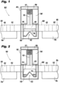
Fig. 1 is a schematic side elevation view of an embodiment of a fuse constructed in accordance with the present disclosure, showing the bus bar and arc interrupter; -
Fig. 2 is a schematic side elevation view of the fuse ofFig. 1 , showing the second material from the pocket of the bus bar melted at the beginning of a circuit interrupt event; -
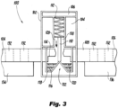
Fig. 3 is a schematic side elevation view of the fuse ofFig. 1 , showing the first or main material of the bus bar also melted, with the arc interrupter blocking between the two separate portions of the bus bar to inhibit arcing from one portion to the other of the bus bar; -
Fig. 4 is a schematic plan view of the fuse ofFig. 1 , showing lateral edges of the arc interrupter closely toleranced to the lateral walls of the housing; and -
Fig. 5 is a schematic plan view of the fuse ofFig. 1 , showing another arc interrupter having an H-shaped cross-sectional profile. - Reference will now be made to the drawings wherein like reference numerals identify similar structural features or aspects of the subject disclosure. For purposes of explanation and illustration, and not limitation, a partial view of an embodiment of a fuse in accordance with the disclosure is shown in
Fig. 1 and is designated generally byreference character 100. Other embodiments of systems in accordance with the disclosure, or aspects thereof, are provided inFigs. 2-5 , as will be described. The systems and methods described herein can be used to mitigate and/or eliminate arcing through plasma and/or particles in a fuse housing after the fuse's bus bar has melted to interrupt a faulted circuit. - The
fuse 100 includes ahousing 102 manufactured of a ceramic material or any nonconductive material coated inside with aceramic material 104 and enclosed by acap 106. Abus bar 108 extends through thehousing 102. Anarc interrupter 110 is positioned inside thehousing 102. Abiasing element 112, such as a spring or the like, is compressed between thecap 106 of thehousing 102 and thearc interrupter 110 to bias thearc interrupter 110 toward and against thebus bar 108 - With continued reference to
Fig. 1 , the bus bar includes apocket 114 defined therein. The wherein thebus bar 108 is of a first material, and asecond material 116 is seated within thepocket 114. Both thepocket 114 andsecond material 116 are within thehousing 102. The first material, i.e. thebus bar 108, has a higher melting temperature than thesecond material 116. Both the first material and thesecond material 116 are electrically conductive. - With reference now to
Fig. 2 , areservoir 118 is defined in thehousing 102 below thepocket 114 in thebus bar 108 with respect to gravity, i.e. as oriented inFigs. 1-3 , for receiving thesecond material 116 in molten form during circuit interrupt. As it has the lower melting temperature, during a circuit interrupt event, thesecond material 116 melts before the first material of thebus bar 108, as shown inFig 2 . The reduction in electrical cross-sectional area of thebus bar 108 intensifies the heating in thenarrow portion 120 of thebus bar 108 proximate thepocket 114, helping insure thenarrow portion 120 is next to melt. - With reference now to
Fig. 3 , aflow diverter 122 extends upward from thereservoir 118. Theflow diverter 122 is configured to divert molten material (thesecond material 116 and material from thenarrow portion 120 of the bus bar 108) away from a center of thehousing 102. Theflow diverter 122, biasingmember 112, andarc interrupter 110 are configured to drive thearc interrupter 110 into, i.e., against, theflow diverter 122 during circuit interrupt as thenarrow portion 120 of thebus bar 108 melts/ablates away. The movement of thearc interrupter 110 is from the position shown inFig. 2 to the position shown inFig. 3 . This forms a barrier between the twoportions bus bar 108, as well as between theleft portion 128 of the interior of thehousing 102 and theright portion 130 of the interior of thehousing 102 as oriented inFig. 3 to separate the twoportions bus bar 102 and the interior of thehousing 102 during circuit interruption. This separation mitigates and/or eliminates arcing from oneportion bus bar 108 to theother portion bus bar 108, to help ensure complete circuit breaking. - With continued reference to
Fig. 3 , afirst portion 124 of thebus bar 108 outside of thehousing 102 can include at least onefastener opening 132, e.g. four as shown inFigs. 4-5 or any other suitable number, therethrough for connecting thebus bar 108 to afirst contact 134 in an electrical line. Asecond portion 126 of the bus bar outside thehousing 102 opposite thefirst portion 124 can similarly include at least onefastener opening 132 therethrough for connecting thebus bar 108 to asecond contact 136 in an electrical line in series with thefirst contact 134 through the bus bar when there is no need for circuit interrupting, e.g. as shown inFig. 1 . - With reference now to
Fig. 4 ,lateral edges 138 of the arc interrupter are toleranced close tolateral walls 140 of thehousing 102 to reduce or prevent flow of particles around thearc interrupter 110 during a circuit interrupt event as shown inFigs. 2-3 . As shown inFig. 5 , this tolerancing can be relaxed, e.g. if thelateral edges 138 of the arc interrupter include laterally extendingflanges 142, giving thearc interrupter 110 an H-shaped or other appropriate cross-sectional profile as viewed in plan view as inFig. 5 . The laterally extendingflanges 142 form a tortuous path with thehousing 102 to reduce or prevent flow of particles around thearc interrupter 110 during a circuit interrupt event as shown inFigs. 2-3 . - Potential benefits of systems and methods as disclosed herein include the following. Fuse 102 can facilitate increases in the present aerospace industry feeder and component sizes to allow for megawatt power level electrical systems for electric propulsion and other high energy applications. The breaking capacity (interrupting rating) of the
fuse 102 can be tuned to different amperages and ambient temperatures by varying the higher and lower melting material's material composition and geometry. The spring-loadedarc interrupter 110, when deployed, can be an insulation barrier between the input and output, e.g.bus bar portions e.g. openings 132, on each side of thefuse 102 allow for lower contact resistance with thebus bar conductors fuse bus bar 108 can be tuned to match the input/output bus bars orcontacts - The methods and systems of the present disclosure, as described above and shown in the drawings, provide for mitigating and/or eliminating arcing through plasma and/or particles in a fuse housing. While the apparatus and methods of the subject disclosure have been shown and described with reference to preferred embodiments, those skilled in the art will readily appreciate that changes and/or modifications may be made thereto without departing from the scope of the subject disclosure.
Claims (15)
- A fuse (100) comprising:a housing (102);a bus bar (108) extending through the housing (102);an arc interrupter (110) positioned inside the housing (102); anda biasing element (112) compressed between the housing (102) and the arc interrupter (110) to bias the arc interrupter (110) toward the bus bar (108) to separate two portions of the bus bar (108) during circuit interruption to mitigate arcing from one portion of the bus bar to the other portion of the bus bar.
- The fuse as recited in claim 1, wherein the bus bar (108) includes a pocket (114) defined therein wherein the bus bar (108) is of a first material, and wherein a second material is seated within the pocket (114).
- The fuse as recited in claim 2, wherein the pocket (114) and second material are within the housing (102).
- The fuse as recited in claim 3, wherein the first material has a higher melting temperature than the second material, and preferably wherein both the first material and the second material are electrically conductive.
- The fuse as recited in claim 3, wherein a reservoir (118) is defined in the housing (102) below the pocket (114) in the bus bar (108) with respect to gravity for receiving the second material in molten form during circuit interrupt, and preferably wherein a flow diverter (122) extends upward from the reservoir (118) wherein the flow diverter (122) is configured to divert molten material away from a center of the housing (102), and more preferably wherein the flow diverter (122), biasing member (112), and arc interrupter (110) are configured to drive the arc interrupter (110) into the flow diverter (122) during circuit interrupt to form a barrier between the two portions of the bus bar (108).
- The fuse as recited in any preceding claim, wherein the housing (102) is ceramic or is coated inside with a ceramic material.
- The fuse as recited in any preceding claim, wherein lateral edges (138) of the arc interrupter (110) are toleranced close to lateral walls (140) of the housing (102) to reduce or prevent flow of particles around the arc interrupter (110).
- The fuse as recited in any preceding claim, wherein lateral edges (138) of the arc interrupter (110) include laterally extending flanges (142), giving the arc interrupter (110) an H-shaped cross-sectional profile, wherein the laterally extending flanges (142) form a tortuous path with the housing (102) to reduce or prevent flow of particles around the arc interrupter (110).
- The fuse as recited in any preceding claim, wherein a first portion of the bus bar (108) outside the housing (102) includes at least one fastener opening (132) therethrough for connecting the bus bar to a first contact in an electrical line, and wherein a second portion of the bus bar (108) outside the housing (102) opposite the first portion includes at least one fastener opening (132) therethrough for connecting the bus bar to a second contact in an electrical line in series with the first contact through the bus bar.
- A fuse comprising:a fuse housing (102); anda bus bar (108) extending through the housing (102), wherein the bus bar (108) includes a pocket (114) defined therein wherein the bus bar (108) is of a first material, and wherein a second material is seated within the pocket (114).
- The fuse as recited in claim 10, wherein the pocket (114) and second material are within the housing (102).
- The fuse as recited in claim 11, wherein the first material has a higher melting temperature than the second material.
- The fuse as recited in claim 12, wherein both the first material and the second material are electrically conductive, and preferably wherein a reservoir (118) is defined in the housing (102) below the pocket (114) in the bus bar (108) with respect to gravity for receiving the second material in molten form during circuit interrupt, and more preferably wherein a flow diverter (122) extends upward from the reservoir (118) wherein the flow diverter (122) is configured to divert molten material away from a center of the housing (102).
- The fuse as recited in claim 12, wherein the housing (102) is coated inside with a ceramic material.
- The fuse as recited in claim 12, wherein a first portion of the bus bar (108) outside the housing (102) includes at least one fastener opening (132) therethrough for connecting the bus bar to a first contact in an electrical line, and wherein a second portion of the bus bar (108) outside the housing (102) opposite the first portion includes at least one fastener opening (132) therethrough for connecting the bus bar to a second contact in an electrical line in series with the first contact through the bus bar.
Applications Claiming Priority (1)
| Application Number | Priority Date | Filing Date | Title |
|---|---|---|---|
| US17/544,398 US11557451B1 (en) | 2021-12-07 | 2021-12-07 | High voltage high current fuse with arc interrupter |
Publications (3)
| Publication Number | Publication Date |
|---|---|
| EP4195232A2 true EP4195232A2 (en) | 2023-06-14 |
| EP4195232A3 EP4195232A3 (en) | 2023-08-09 |
| EP4195232B1 EP4195232B1 (en) | 2026-03-04 |
Family
ID=84367157
Family Applications (1)
| Application Number | Title | Priority Date | Filing Date |
|---|---|---|---|
| EP22210559.5A Active EP4195232B1 (en) | 2021-12-07 | 2022-11-30 | High voltage high current fuse with arc interrupter |
Country Status (2)
| Country | Link |
|---|---|
| US (1) | US11557451B1 (en) |
| EP (1) | EP4195232B1 (en) |
Family Cites Families (15)
| Publication number | Priority date | Publication date | Assignee | Title |
|---|---|---|---|---|
| US4451814A (en) * | 1982-06-14 | 1984-05-29 | Fasco Controls Corporation | Non-resettable thermal fuse |
| US4963850A (en) * | 1989-03-30 | 1990-10-16 | General Electric Company | Thermal withstand capability of a filament wound epoxy fuse body in a current-limiting fuse |
| DE19817133A1 (en) * | 1998-04-19 | 1999-10-28 | Lell Peter | Power disconnecting switch for emergency use in high current circuits, especially vehicles |
| US6430019B1 (en) * | 1998-06-08 | 2002-08-06 | Ferraz S.A. | Circuit protection device |
| US20090189730A1 (en) * | 2008-01-30 | 2009-07-30 | Littelfuse, Inc. | Low temperature fuse |
| DE112011105340T5 (en) * | 2011-06-17 | 2014-03-13 | Littelfuse, Inc. | Thermal Metal Oxide Varistor Circuit Protector |
| JP6040580B2 (en) * | 2012-06-12 | 2016-12-07 | 株式会社村田製作所 | fuse |
| DE102012221664B4 (en) * | 2012-09-25 | 2022-04-21 | Te Connectivity Germany Gmbh | short-circuit switch |
| JP6437239B2 (en) * | 2013-08-28 | 2018-12-12 | デクセリアルズ株式会社 | Fuse element, fuse element |
| DE102015213050A1 (en) * | 2015-07-13 | 2017-01-19 | Phoenix Contact Gmbh & Co. Kg | Varistor with a separator |
| US10573876B1 (en) | 2016-07-22 | 2020-02-25 | Qingcheng Zeng | Fuse design for a lithium-ion battery |
| DE102016122424B4 (en) * | 2016-11-22 | 2023-06-07 | Auto-Kabel Management Gmbh | Arc breaker disconnect device |
| US10964988B2 (en) | 2018-10-08 | 2021-03-30 | Ford Global Technologies, Llc | Fusible bimetallic bus bars for battery arrays |
| US12191525B2 (en) | 2018-11-16 | 2025-01-07 | Vehicle Energy Japan Inc. | Battery module |
| US11355300B2 (en) | 2019-05-07 | 2022-06-07 | Littelfuse, Inc. | Active/passive automotive fuse module |
-
2021
- 2021-12-07 US US17/544,398 patent/US11557451B1/en active Active
-
2022
- 2022-11-30 EP EP22210559.5A patent/EP4195232B1/en active Active
Also Published As
| Publication number | Publication date |
|---|---|
| EP4195232B1 (en) | 2026-03-04 |
| US11557451B1 (en) | 2023-01-17 |
| EP4195232A3 (en) | 2023-08-09 |
Similar Documents
| Publication | Publication Date | Title |
|---|---|---|
| EP2416405B1 (en) | Battery pack with cell-level fusing and method of using same | |
| US8133608B2 (en) | Battery pack with cell-level fusing | |
| US10276314B2 (en) | Switching and protection device for high-voltage wiring system | |
| US7529072B2 (en) | Protection apparatus | |
| US8009401B2 (en) | Voltage surge protection device comprising selective disconnection means | |
| US10483061B2 (en) | Protective device | |
| US10395877B2 (en) | Protective device | |
| US11087940B2 (en) | Electrical interruption device | |
| AU2015356244A1 (en) | DC high-speed circuit breaker | |
| KR20130000093U (en) | A circuit braker | |
| CN114551131A (en) | Direct current arc extinguishing device and motor type direct current switch equipment | |
| CN111916321A (en) | Active/Passive Automotive Fuse Modules | |
| US12519189B2 (en) | Thermally disconnecting high power busbars for battery system propagation control | |
| US9088155B2 (en) | Surge protection device | |
| US11557451B1 (en) | High voltage high current fuse with arc interrupter | |
| Koprivsek | Advanced solutions in over-current protection of hvdc circuit of battery-powered electric vehicle | |
| CN103117198B (en) | Device for protecting an electric circuit supplied by alternating current, method therefor, and electric contactor | |
| CN115863925A (en) | Bus fuse between batteries | |
| US20250118503A1 (en) | Contactor with arc guides and protection integrated into the arc guides, corresponding system and aircraft | |
| KR20190095752A (en) | Fusing busbar | |
| CN220873514U (en) | A fuse with faster medium-rate overcurrent fusing speed | |
| JP7081492B2 (en) | Connecting members, moving bodies and power supply systems | |
| CN117133612A (en) | A fuse that speeds up medium-rate overcurrent fusing speed | |
| CN103730299A (en) | Fuse for protecting solar photovoltaic power generation system | |
| CN116895498A (en) | Fuse assemblies and protective circuits and methods including the same |
Legal Events
| Date | Code | Title | Description |
|---|---|---|---|
| PUAI | Public reference made under article 153(3) epc to a published international application that has entered the european phase |
Free format text: ORIGINAL CODE: 0009012 |
|
| STAA | Information on the status of an ep patent application or granted ep patent |
Free format text: STATUS: THE APPLICATION HAS BEEN PUBLISHED |
|
| AK | Designated contracting states |
Kind code of ref document: A2 Designated state(s): AL AT BE BG CH CY CZ DE DK EE ES FI FR GB GR HR HU IE IS IT LI LT LU LV MC ME MK MT NL NO PL PT RO RS SE SI SK SM TR |
|
| PUAL | Search report despatched |
Free format text: ORIGINAL CODE: 0009013 |
|
| AK | Designated contracting states |
Kind code of ref document: A3 Designated state(s): AL AT BE BG CH CY CZ DE DK EE ES FI FR GB GR HR HU IE IS IT LI LT LU LV MC ME MK MT NL NO PL PT RO RS SE SI SK SM TR |
|
| RIC1 | Information provided on ipc code assigned before grant |
Ipc: H01H 85/36 20060101ALN20230706BHEP Ipc: H01H 85/143 20060101ALN20230706BHEP Ipc: H01H 9/32 20060101ALN20230706BHEP Ipc: H01H 85/38 20060101ALI20230706BHEP Ipc: H01H 85/175 20060101ALI20230706BHEP Ipc: H01H 85/10 20060101ALI20230706BHEP Ipc: H01H 85/06 20060101ALI20230706BHEP Ipc: H01H 37/76 20060101AFI20230706BHEP |
|
| STAA | Information on the status of an ep patent application or granted ep patent |
Free format text: STATUS: REQUEST FOR EXAMINATION WAS MADE |
|
| 17P | Request for examination filed |
Effective date: 20240308 |
|
| RBV | Designated contracting states (corrected) |
Designated state(s): AL AT BE BG CH CY CZ DE DK EE ES FI FR GB GR HR HU IE IS IT LI LT LU LV MC ME MK MT NL NO PL PT RO RS SE SI SK SM TR |
|
| GRAP | Despatch of communication of intention to grant a patent |
Free format text: ORIGINAL CODE: EPIDOSNIGR1 |
|
| STAA | Information on the status of an ep patent application or granted ep patent |
Free format text: STATUS: GRANT OF PATENT IS INTENDED |
|
| RIC1 | Information provided on ipc code assigned before grant |
Ipc: H01H 37/76 20060101AFI20250723BHEP Ipc: H01H 85/06 20060101ALI20250723BHEP Ipc: H01H 85/10 20060101ALI20250723BHEP Ipc: H01H 85/175 20060101ALI20250723BHEP Ipc: H01H 85/38 20060101ALI20250723BHEP Ipc: H01H 9/32 20060101ALN20250723BHEP Ipc: H01H 85/143 20060101ALN20250723BHEP Ipc: H01H 85/36 20060101ALN20250723BHEP |
|
| INTG | Intention to grant announced |
Effective date: 20250806 |
|
| GRAJ | Information related to disapproval of communication of intention to grant by the applicant or resumption of examination proceedings by the epo deleted |
Free format text: ORIGINAL CODE: EPIDOSDIGR1 |
|
| STAA | Information on the status of an ep patent application or granted ep patent |
Free format text: STATUS: REQUEST FOR EXAMINATION WAS MADE |
|
| GRAP | Despatch of communication of intention to grant a patent |
Free format text: ORIGINAL CODE: EPIDOSNIGR1 |
|
| STAA | Information on the status of an ep patent application or granted ep patent |
Free format text: STATUS: GRANT OF PATENT IS INTENDED |
|
| INTC | Intention to grant announced (deleted) | ||
| RIC1 | Information provided on ipc code assigned before grant |
Ipc: H01H 37/76 20060101AFI20251124BHEP Ipc: H01H 85/06 20060101ALI20251124BHEP Ipc: H01H 85/10 20060101ALI20251124BHEP Ipc: H01H 85/175 20060101ALI20251124BHEP Ipc: H01H 85/38 20060101ALI20251124BHEP Ipc: H01H 9/32 20060101ALN20251124BHEP Ipc: H01H 85/143 20060101ALN20251124BHEP Ipc: H01H 85/36 20060101ALN20251124BHEP |
|
| INTG | Intention to grant announced |
Effective date: 20251205 |
|
| GRAS | Grant fee paid |
Free format text: ORIGINAL CODE: EPIDOSNIGR3 |
|
| GRAA | (expected) grant |
Free format text: ORIGINAL CODE: 0009210 |
|
| STAA | Information on the status of an ep patent application or granted ep patent |
Free format text: STATUS: THE PATENT HAS BEEN GRANTED |
|
| AK | Designated contracting states |
Kind code of ref document: B1 Designated state(s): AL AT BE BG CH CY CZ DE DK EE ES FI FR GB GR HR HU IE IS IT LI LT LU LV MC ME MK MT NL NO PL PT RO RS SE SI SK SM TR |
|
| REG | Reference to a national code |
Ref country code: CH Ref legal event code: F10 Free format text: ST27 STATUS EVENT CODE: U-0-0-F10-F00 (AS PROVIDED BY THE NATIONAL OFFICE) Effective date: 20260304 Ref country code: GB Ref legal event code: FG4D |
|
| REG | Reference to a national code |
Ref country code: DE Ref legal event code: R096 Ref document number: 602022031539 Country of ref document: DE |
|
| REG | Reference to a national code |
Ref country code: IE Ref legal event code: FG4D |
|
| PG25 | Lapsed in a contracting state [announced via postgrant information from national office to epo] |
Ref country code: RS Free format text: LAPSE BECAUSE OF FAILURE TO SUBMIT A TRANSLATION OF THE DESCRIPTION OR TO PAY THE FEE WITHIN THE PRESCRIBED TIME-LIMIT Effective date: 20260604 |
|
| PG25 | Lapsed in a contracting state [announced via postgrant information from national office to epo] |
Ref country code: ES Free format text: LAPSE BECAUSE OF FAILURE TO SUBMIT A TRANSLATION OF THE DESCRIPTION OR TO PAY THE FEE WITHIN THE PRESCRIBED TIME-LIMIT Effective date: 20260304 |
|
| REG | Reference to a national code |
Ref country code: NL Ref legal event code: MP Effective date: 20260304 |
|
| PG25 | Lapsed in a contracting state [announced via postgrant information from national office to epo] |
Ref country code: PL Free format text: LAPSE BECAUSE OF FAILURE TO SUBMIT A TRANSLATION OF THE DESCRIPTION OR TO PAY THE FEE WITHIN THE PRESCRIBED TIME-LIMIT Effective date: 20260304 |
|
| PG25 | Lapsed in a contracting state [announced via postgrant information from national office to epo] |
Ref country code: GR Free format text: LAPSE BECAUSE OF FAILURE TO SUBMIT A TRANSLATION OF THE DESCRIPTION OR TO PAY THE FEE WITHIN THE PRESCRIBED TIME-LIMIT Effective date: 20260605 |
|
| REG | Reference to a national code |
Ref country code: LT Ref legal event code: MG9D |
|
| PG25 | Lapsed in a contracting state [announced via postgrant information from national office to epo] |
Ref country code: LT Free format text: LAPSE BECAUSE OF FAILURE TO SUBMIT A TRANSLATION OF THE DESCRIPTION OR TO PAY THE FEE WITHIN THE PRESCRIBED TIME-LIMIT Effective date: 20260304 |
|
| PG25 | Lapsed in a contracting state [announced via postgrant information from national office to epo] |
Ref country code: NO Free format text: LAPSE BECAUSE OF FAILURE TO SUBMIT A TRANSLATION OF THE DESCRIPTION OR TO PAY THE FEE WITHIN THE PRESCRIBED TIME-LIMIT Effective date: 20260604 |
|
| PG25 | Lapsed in a contracting state [announced via postgrant information from national office to epo] |
Ref country code: SE Free format text: LAPSE BECAUSE OF FAILURE TO SUBMIT A TRANSLATION OF THE DESCRIPTION OR TO PAY THE FEE WITHIN THE PRESCRIBED TIME-LIMIT Effective date: 20260304 Ref country code: FI Free format text: LAPSE BECAUSE OF FAILURE TO SUBMIT A TRANSLATION OF THE DESCRIPTION OR TO PAY THE FEE WITHIN THE PRESCRIBED TIME-LIMIT Effective date: 20260304 |
|
| PG25 | Lapsed in a contracting state [announced via postgrant information from national office to epo] |
Ref country code: HR Free format text: LAPSE BECAUSE OF FAILURE TO SUBMIT A TRANSLATION OF THE DESCRIPTION OR TO PAY THE FEE WITHIN THE PRESCRIBED TIME-LIMIT Effective date: 20260304 |
|
| PG25 | Lapsed in a contracting state [announced via postgrant information from national office to epo] |
Ref country code: LV Free format text: LAPSE BECAUSE OF FAILURE TO SUBMIT A TRANSLATION OF THE DESCRIPTION OR TO PAY THE FEE WITHIN THE PRESCRIBED TIME-LIMIT Effective date: 20260304 |
|
| PG25 | Lapsed in a contracting state [announced via postgrant information from national office to epo] |
Ref country code: BG Free format text: LAPSE BECAUSE OF FAILURE TO SUBMIT A TRANSLATION OF THE DESCRIPTION OR TO PAY THE FEE WITHIN THE PRESCRIBED TIME-LIMIT Effective date: 20260304 |