EP4195207A1 - Oxram/feram mixed technology nonvolatile memories - Google Patents
Oxram/feram mixed technology nonvolatile memories Download PDFInfo
- Publication number
- EP4195207A1 EP4195207A1 EP22211794.7A EP22211794A EP4195207A1 EP 4195207 A1 EP4195207 A1 EP 4195207A1 EP 22211794 A EP22211794 A EP 22211794A EP 4195207 A1 EP4195207 A1 EP 4195207A1
- Authority
- EP
- European Patent Office
- Prior art keywords
- read
- configuration
- write
- memory cell
- circuit
- Prior art date
- Legal status (The legal status is an assumption and is not a legal conclusion. Google has not performed a legal analysis and makes no representation as to the accuracy of the status listed.)
- Granted
Links
- 230000015654 memory Effects 0.000 title claims abstract description 260
- 238000005516 engineering process Methods 0.000 title description 8
- 238000013500 data storage Methods 0.000 claims abstract description 44
- 239000004020 conductor Substances 0.000 claims abstract description 8
- 239000000463 material Substances 0.000 claims abstract description 7
- 210000004027 cell Anatomy 0.000 claims description 146
- 239000011159 matrix material Substances 0.000 claims description 35
- 238000003860 storage Methods 0.000 claims description 27
- 230000007704 transition Effects 0.000 claims description 26
- 238000012432 intermediate storage Methods 0.000 claims description 22
- 238000013528 artificial neural network Methods 0.000 claims description 17
- 238000006243 chemical reaction Methods 0.000 claims description 16
- 230000010287 polarization Effects 0.000 claims description 16
- 238000004422 calculation algorithm Methods 0.000 claims description 12
- 230000000946 synaptic effect Effects 0.000 claims description 11
- 230000003213 activating effect Effects 0.000 claims description 10
- 230000013016 learning Effects 0.000 claims description 10
- 230000000903 blocking effect Effects 0.000 claims description 8
- 238000001514 detection method Methods 0.000 claims description 8
- 238000000034 method Methods 0.000 claims description 8
- 230000009466 transformation Effects 0.000 claims description 8
- 101150098958 CMD1 gene Proteins 0.000 claims description 7
- 101100382321 Caenorhabditis elegans cal-1 gene Proteins 0.000 claims description 7
- 229910000449 hafnium oxide Inorganic materials 0.000 claims description 5
- WIHZLLGSGQNAGK-UHFFFAOYSA-N hafnium(4+);oxygen(2-) Chemical compound [O-2].[O-2].[Hf+4] WIHZLLGSGQNAGK-UHFFFAOYSA-N 0.000 claims description 5
- 239000000758 substrate Substances 0.000 claims description 5
- 238000007514 turning Methods 0.000 claims description 5
- NRTOMJZYCJJWKI-UHFFFAOYSA-N Titanium nitride Chemical compound [Ti]#N NRTOMJZYCJJWKI-UHFFFAOYSA-N 0.000 claims description 4
- 230000002427 irreversible effect Effects 0.000 claims description 4
- 239000004065 semiconductor Substances 0.000 claims description 4
- 229910052710 silicon Inorganic materials 0.000 claims description 4
- 239000010703 silicon Substances 0.000 claims description 4
- 210000002569 neuron Anatomy 0.000 claims description 3
- 230000001360 synchronised effect Effects 0.000 claims description 3
- 238000004364 calculation method Methods 0.000 description 29
- 235000021183 entrée Nutrition 0.000 description 20
- 230000015572 biosynthetic process Effects 0.000 description 16
- 230000007246 mechanism Effects 0.000 description 10
- 230000006399 behavior Effects 0.000 description 8
- 238000010586 diagram Methods 0.000 description 8
- 101150110971 CIN7 gene Proteins 0.000 description 7
- 101100286980 Daucus carota INV2 gene Proteins 0.000 description 7
- 101150110298 INV1 gene Proteins 0.000 description 7
- 101100397044 Xenopus laevis invs-a gene Proteins 0.000 description 7
- 101100397045 Xenopus laevis invs-b gene Proteins 0.000 description 7
- 238000012986 modification Methods 0.000 description 7
- 229910052760 oxygen Inorganic materials 0.000 description 7
- 239000001301 oxygen Substances 0.000 description 7
- QVGXLLKOCUKJST-UHFFFAOYSA-N atomic oxygen Chemical compound [O] QVGXLLKOCUKJST-UHFFFAOYSA-N 0.000 description 5
- 230000008901 benefit Effects 0.000 description 5
- 230000000670 limiting effect Effects 0.000 description 5
- 230000009471 action Effects 0.000 description 4
- 230000004048 modification Effects 0.000 description 4
- 230000009467 reduction Effects 0.000 description 4
- XUIMIQQOPSSXEZ-UHFFFAOYSA-N Silicon Chemical compound [Si] XUIMIQQOPSSXEZ-UHFFFAOYSA-N 0.000 description 3
- 230000004913 activation Effects 0.000 description 3
- 239000003990 capacitor Substances 0.000 description 3
- 238000007600 charging Methods 0.000 description 3
- 239000003989 dielectric material Substances 0.000 description 3
- 230000001747 exhibiting effect Effects 0.000 description 3
- 230000006870 function Effects 0.000 description 3
- 229910052751 metal Inorganic materials 0.000 description 3
- 239000002184 metal Substances 0.000 description 3
- 230000000051 modifying effect Effects 0.000 description 3
- 230000003071 parasitic effect Effects 0.000 description 3
- 230000004044 response Effects 0.000 description 3
- 230000001052 transient effect Effects 0.000 description 3
- VYPSYNLAJGMNEJ-UHFFFAOYSA-N Silicium dioxide Chemical compound O=[Si]=O VYPSYNLAJGMNEJ-UHFFFAOYSA-N 0.000 description 2
- ATJFFYVFTNAWJD-UHFFFAOYSA-N Tin Chemical compound [Sn] ATJFFYVFTNAWJD-UHFFFAOYSA-N 0.000 description 2
- 238000013473 artificial intelligence Methods 0.000 description 2
- 239000013078 crystal Substances 0.000 description 2
- 230000001066 destructive effect Effects 0.000 description 2
- 238000005265 energy consumption Methods 0.000 description 2
- 230000006872 improvement Effects 0.000 description 2
- -1 oxygen ions Chemical class 0.000 description 2
- 239000000523 sample Substances 0.000 description 2
- 230000003068 static effect Effects 0.000 description 2
- 210000000225 synapse Anatomy 0.000 description 2
- 238000013519 translation Methods 0.000 description 2
- 239000003039 volatile agent Substances 0.000 description 2
- 229910004298 SiO 2 Inorganic materials 0.000 description 1
- 240000008042 Zea mays Species 0.000 description 1
- 239000000956 alloy Substances 0.000 description 1
- 229910045601 alloy Inorganic materials 0.000 description 1
- 238000013529 biological neural network Methods 0.000 description 1
- 230000008859 change Effects 0.000 description 1
- 230000000295 complement effect Effects 0.000 description 1
- 230000009850 completed effect Effects 0.000 description 1
- 238000005094 computer simulation Methods 0.000 description 1
- 230000008021 deposition Effects 0.000 description 1
- 230000005684 electric field Effects 0.000 description 1
- 239000012777 electrically insulating material Substances 0.000 description 1
- 238000005530 etching Methods 0.000 description 1
- 238000011156 evaluation Methods 0.000 description 1
- CJNBYAVZURUTKZ-UHFFFAOYSA-N hafnium(IV) oxide Inorganic materials O=[Hf]=O CJNBYAVZURUTKZ-UHFFFAOYSA-N 0.000 description 1
- 230000001965 increasing effect Effects 0.000 description 1
- 238000002347 injection Methods 0.000 description 1
- 239000007924 injection Substances 0.000 description 1
- 239000012212 insulator Substances 0.000 description 1
- 230000003993 interaction Effects 0.000 description 1
- 238000001459 lithography Methods 0.000 description 1
- 238000011068 loading method Methods 0.000 description 1
- 238000004519 manufacturing process Methods 0.000 description 1
- 229910044991 metal oxide Inorganic materials 0.000 description 1
- 150000004706 metal oxides Chemical class 0.000 description 1
- 230000003278 mimic effect Effects 0.000 description 1
- 125000004430 oxygen atom Chemical group O* 0.000 description 1
- RVTZCBVAJQQJTK-UHFFFAOYSA-N oxygen(2-);zirconium(4+) Chemical compound [O-2].[O-2].[Zr+4] RVTZCBVAJQQJTK-UHFFFAOYSA-N 0.000 description 1
- 230000008569 process Effects 0.000 description 1
- 230000000750 progressive effect Effects 0.000 description 1
- 230000003252 repetitive effect Effects 0.000 description 1
- 230000002441 reversible effect Effects 0.000 description 1
- 235000012239 silicon dioxide Nutrition 0.000 description 1
- 239000000377 silicon dioxide Substances 0.000 description 1
- 239000000243 solution Substances 0.000 description 1
- 230000000638 stimulation Effects 0.000 description 1
- 238000012546 transfer Methods 0.000 description 1
- 229910001928 zirconium oxide Inorganic materials 0.000 description 1
Images


Classifications
-
- G—PHYSICS
- G11—INFORMATION STORAGE
- G11C—STATIC STORES
- G11C11/00—Digital stores characterised by the use of particular electric or magnetic storage elements; Storage elements therefor
- G11C11/21—Digital stores characterised by the use of particular electric or magnetic storage elements; Storage elements therefor using electric elements
- G11C11/22—Digital stores characterised by the use of particular electric or magnetic storage elements; Storage elements therefor using electric elements using ferroelectric elements
- G11C11/221—Digital stores characterised by the use of particular electric or magnetic storage elements; Storage elements therefor using electric elements using ferroelectric elements using ferroelectric capacitors
-
- G—PHYSICS
- G06—COMPUTING; CALCULATING OR COUNTING
- G06N—COMPUTING ARRANGEMENTS BASED ON SPECIFIC COMPUTATIONAL MODELS
- G06N3/00—Computing arrangements based on biological models
- G06N3/02—Neural networks
- G06N3/06—Physical realisation, i.e. hardware implementation of neural networks, neurons or parts of neurons
- G06N3/063—Physical realisation, i.e. hardware implementation of neural networks, neurons or parts of neurons using electronic means
-
- G—PHYSICS
- G06—COMPUTING; CALCULATING OR COUNTING
- G06N—COMPUTING ARRANGEMENTS BASED ON SPECIFIC COMPUTATIONAL MODELS
- G06N3/00—Computing arrangements based on biological models
- G06N3/02—Neural networks
- G06N3/08—Learning methods
-
- G—PHYSICS
- G11—INFORMATION STORAGE
- G11C—STATIC STORES
- G11C11/00—Digital stores characterised by the use of particular electric or magnetic storage elements; Storage elements therefor
- G11C11/005—Digital stores characterised by the use of particular electric or magnetic storage elements; Storage elements therefor comprising combined but independently operative RAM-ROM, RAM-PROM, RAM-EPROM cells
-
- G—PHYSICS
- G11—INFORMATION STORAGE
- G11C—STATIC STORES
- G11C11/00—Digital stores characterised by the use of particular electric or magnetic storage elements; Storage elements therefor
- G11C11/21—Digital stores characterised by the use of particular electric or magnetic storage elements; Storage elements therefor using electric elements
- G11C11/22—Digital stores characterised by the use of particular electric or magnetic storage elements; Storage elements therefor using electric elements using ferroelectric elements
- G11C11/225—Auxiliary circuits
- G11C11/2273—Reading or sensing circuits or methods
-
- G—PHYSICS
- G11—INFORMATION STORAGE
- G11C—STATIC STORES
- G11C11/00—Digital stores characterised by the use of particular electric or magnetic storage elements; Storage elements therefor
- G11C11/21—Digital stores characterised by the use of particular electric or magnetic storage elements; Storage elements therefor using electric elements
- G11C11/22—Digital stores characterised by the use of particular electric or magnetic storage elements; Storage elements therefor using electric elements using ferroelectric elements
- G11C11/225—Auxiliary circuits
- G11C11/2275—Writing or programming circuits or methods
-
- G—PHYSICS
- G11—INFORMATION STORAGE
- G11C—STATIC STORES
- G11C11/00—Digital stores characterised by the use of particular electric or magnetic storage elements; Storage elements therefor
- G11C11/21—Digital stores characterised by the use of particular electric or magnetic storage elements; Storage elements therefor using electric elements
- G11C11/22—Digital stores characterised by the use of particular electric or magnetic storage elements; Storage elements therefor using electric elements using ferroelectric elements
- G11C11/225—Auxiliary circuits
- G11C11/2293—Timing circuits or methods
-
- G—PHYSICS
- G11—INFORMATION STORAGE
- G11C—STATIC STORES
- G11C13/00—Digital stores characterised by the use of storage elements not covered by groups G11C11/00, G11C23/00, or G11C25/00
- G11C13/0002—Digital stores characterised by the use of storage elements not covered by groups G11C11/00, G11C23/00, or G11C25/00 using resistive RAM [RRAM] elements
- G11C13/0007—Digital stores characterised by the use of storage elements not covered by groups G11C11/00, G11C23/00, or G11C25/00 using resistive RAM [RRAM] elements comprising metal oxide memory material, e.g. perovskites
-
- G—PHYSICS
- G11—INFORMATION STORAGE
- G11C—STATIC STORES
- G11C13/00—Digital stores characterised by the use of storage elements not covered by groups G11C11/00, G11C23/00, or G11C25/00
- G11C13/0002—Digital stores characterised by the use of storage elements not covered by groups G11C11/00, G11C23/00, or G11C25/00 using resistive RAM [RRAM] elements
- G11C13/0021—Auxiliary circuits
- G11C13/0023—Address circuits or decoders
- G11C13/0026—Bit-line or column circuits
-
- G—PHYSICS
- G11—INFORMATION STORAGE
- G11C—STATIC STORES
- G11C13/00—Digital stores characterised by the use of storage elements not covered by groups G11C11/00, G11C23/00, or G11C25/00
- G11C13/0002—Digital stores characterised by the use of storage elements not covered by groups G11C11/00, G11C23/00, or G11C25/00 using resistive RAM [RRAM] elements
- G11C13/0021—Auxiliary circuits
- G11C13/004—Reading or sensing circuits or methods
-
- G—PHYSICS
- G11—INFORMATION STORAGE
- G11C—STATIC STORES
- G11C13/00—Digital stores characterised by the use of storage elements not covered by groups G11C11/00, G11C23/00, or G11C25/00
- G11C13/0002—Digital stores characterised by the use of storage elements not covered by groups G11C11/00, G11C23/00, or G11C25/00 using resistive RAM [RRAM] elements
- G11C13/0021—Auxiliary circuits
- G11C13/0061—Timing circuits or methods
-
- G—PHYSICS
- G11—INFORMATION STORAGE
- G11C—STATIC STORES
- G11C13/00—Digital stores characterised by the use of storage elements not covered by groups G11C11/00, G11C23/00, or G11C25/00
- G11C13/0002—Digital stores characterised by the use of storage elements not covered by groups G11C11/00, G11C23/00, or G11C25/00 using resistive RAM [RRAM] elements
- G11C13/0021—Auxiliary circuits
- G11C13/0069—Writing or programming circuits or methods
-
- G—PHYSICS
- G11—INFORMATION STORAGE
- G11C—STATIC STORES
- G11C13/00—Digital stores characterised by the use of storage elements not covered by groups G11C11/00, G11C23/00, or G11C25/00
- G11C13/0002—Digital stores characterised by the use of storage elements not covered by groups G11C11/00, G11C23/00, or G11C25/00 using resistive RAM [RRAM] elements
- G11C13/0021—Auxiliary circuits
- G11C13/004—Reading or sensing circuits or methods
- G11C2013/0045—Read using current through the cell
-
- G—PHYSICS
- G11—INFORMATION STORAGE
- G11C—STATIC STORES
- G11C13/00—Digital stores characterised by the use of storage elements not covered by groups G11C11/00, G11C23/00, or G11C25/00
- G11C13/0002—Digital stores characterised by the use of storage elements not covered by groups G11C11/00, G11C23/00, or G11C25/00 using resistive RAM [RRAM] elements
- G11C13/0021—Auxiliary circuits
- G11C13/004—Reading or sensing circuits or methods
- G11C2013/0054—Read is performed on a reference element, e.g. cell, and the reference sensed value is used to compare the sensed value of the selected cell
-
- G—PHYSICS
- G11—INFORMATION STORAGE
- G11C—STATIC STORES
- G11C2213/00—Indexing scheme relating to G11C13/00 for features not covered by this group
- G11C2213/70—Resistive array aspects
- G11C2213/79—Array wherein the access device being a transistor
-
- G—PHYSICS
- G11—INFORMATION STORAGE
- G11C—STATIC STORES
- G11C2213/00—Indexing scheme relating to G11C13/00 for features not covered by this group
- G11C2213/70—Resistive array aspects
- G11C2213/82—Array having, for accessing a cell, a word line, a bit line and a plate or source line receiving different potentials
-
- H—ELECTRICITY
- H10—SEMICONDUCTOR DEVICES; ELECTRIC SOLID-STATE DEVICES NOT OTHERWISE PROVIDED FOR
- H10N—ELECTRIC SOLID-STATE DEVICES NOT OTHERWISE PROVIDED FOR
- H10N70/00—Solid-state devices having no potential barriers, and specially adapted for rectifying, amplifying, oscillating or switching
- H10N70/20—Multistable switching devices, e.g. memristors
- H10N70/24—Multistable switching devices, e.g. memristors based on migration or redistribution of ionic species, e.g. anions, vacancies
-
- H—ELECTRICITY
- H10—SEMICONDUCTOR DEVICES; ELECTRIC SOLID-STATE DEVICES NOT OTHERWISE PROVIDED FOR
- H10N—ELECTRIC SOLID-STATE DEVICES NOT OTHERWISE PROVIDED FOR
- H10N70/00—Solid-state devices having no potential barriers, and specially adapted for rectifying, amplifying, oscillating or switching
- H10N70/801—Constructional details of multistable switching devices
- H10N70/821—Device geometry
- H10N70/826—Device geometry adapted for essentially vertical current flow, e.g. sandwich or pillar type devices
-
- H—ELECTRICITY
- H10—SEMICONDUCTOR DEVICES; ELECTRIC SOLID-STATE DEVICES NOT OTHERWISE PROVIDED FOR
- H10N—ELECTRIC SOLID-STATE DEVICES NOT OTHERWISE PROVIDED FOR
- H10N70/00—Solid-state devices having no potential barriers, and specially adapted for rectifying, amplifying, oscillating or switching
- H10N70/801—Constructional details of multistable switching devices
- H10N70/881—Switching materials
- H10N70/883—Oxides or nitrides
- H10N70/8833—Binary metal oxides, e.g. TaOx
Definitions
- the invention generally relates to configurable non-volatile memory cells for storing data manipulated by computers to execute a calculation algorithm.
- the calculation algorithm executed requires a considerable number of write and/or read operations in the memory cells according to the invention.
- calculation algorithms can implement several calculation phases: a first phase during which the manipulated variables undergo numerous modifications and a second phase during which the same variables are frozen or undergo few modifications.
- a technical problem to be solved is the improvement of the energy performance and the technological robustness of the storage means for a computer circuit able to carry out a first phase of operation requiring a large number of write operations in the storage means and capable of carrying out a second phase of operation requiring a large number of reading operations of said storage means.
- the scientific publication entitled "Interplay between ferroelectric and resistive switching in doped crystalline HfO2" by Max et al describes a memory component compatible with resistive filament memory operation and ferroelectric memory operation.
- the publication is limited to describing the memory component from a physical point of view as an elementary component.
- the publication does not present a specific implementation in a data storage circuit embedded in a configurable computer circuit according to the specifics of the calculation phase carried out in terms of the number of read and write operations.
- the invention proposes a data storage circuit comprising a matrix of non-volatile memory cells and configurable according to two operating configurations.
- the first configuration corresponds to operation in ferroelectric memory with variable electrical bias (FeRAM) and the second configuration corresponds to operation in resistive memory with variable conductive filament (OxRAM or ReRAM).
- FeRAM ferroelectric memory with variable electrical bias
- OxRAM or ReRAM resistive memory with variable conductive filament
- the memory cells according to the invention are produced by the same stack of thin layers on the same semiconductor substrate for the two operating configurations allowing a dense implementation of memory cells with hybrid technology in the same memory plane. This offers the advantage of a reduction in the surface of the data storage circuit while having an adaptable operation according to the phase executed by the computer in terms of preponderance of the number of read or write operations.
- the invention further proposes a control method making it possible to configure the passage from the first configuration to the second configuration of the memory cells so as to convert the data stored according to the ferroelectric configuration to data stored according to the resistive configuration.
- control means comprise a conversion circuit configured to convert, for each memory cell, the read signal resulting from the first operating configuration into a write control signal compatible with the second operating setup.
- the write circuit is configured to apply to each second input node an electric voltage of transformation to form a conductive filament in the second layer extending from the third layer in each memory cell. Said filament corresponds to a low resistive state.
- the at least one intermediate storage memory is also intended to store each read signal when the second configuration is chosen.
- the conversion circuit is configured to convert, for each memory cell, the read signal resulting from the second operating configuration into a write control signal compatible with the first operating configuration.
- the read circuit comprises a plurality of elementary read circuits each comprising: a comparator for comparing the read voltage and a reference voltage to provide the read signal of the memory cell being read.
- the at least one intermediate storage memory is a synchronous flip-flop.
- the write circuit is configured to rewrite the data read in a memory cell after each read operation when the first configuration is chosen.
- the write circuit is configured to apply a write voltage having an amplitude and/or a sufficient duration to establish a conductive filament passing through an irreversible low resistive state.
- the first and the third layer are made of titanium nitride.
- the second layer is made of hafnium oxide doped with silicon or made of HfZrO 2 .
- the computer is configured to implement an artificial neural network, the neural network being composed of a succession of layers each consisting of a set of neurons, each layer being associated with a set of synaptic coefficients.
- the numerical variables are the synaptic coefficients of the neural network.
- the first operating phase is a learning phase.
- the second operating phase is an inference phase.
- NVM memory structures are made by stacking thin layers on a single SUB semiconductor substrate.
- the stack of thin layers is produced by the usual microtechnical manufacturing processes comprising the deposition of thin layers, etching, lithography and doping.
- all of the NVM memory structures are arranged in a matrix 100.
- a layer of dielectric material can separate the memory structures from the SUB substrate. Said layer is made of silicon dioxide SiO 2 for example.
- the NVM memory structures are etched so that they are separated by an empty space. Alternatively, it is conceivable to separate the memory structures by layers of electrically insulating material in place of the empty spaces.
- Each NVM memory structure according to the invention consists of the stack of thin layers in the following order: a first layer C1 of an electrically conductive material forming a lower electrode EL1; a second layer C2 of a dielectric and ferroelectric material and a third layer C3 of an electrically conductive material forming an upper electrode EL2.
- THE characteristics of the materials constituting the NVM memory structure layers allow said structure to be compatible with two operating configurations of memory technologies: the first operating configuration CONF1 corresponding to a ferroelectric memory with variable electrical polarization; and the second operating configuration CONF2 corresponding to a resistive memory with variable conductive filament.
- the second layer C2 is referred to in the remainder of the description as the “central layer”.
- the first layer C1 (and therefore the lower electrode EL1) and the third layer C3 (and therefore the upper electrode EL2) are made of titanium nitride TiN.
- the choice of titanium nitride TiN makes it possible to avoid the formation of an oxide layer at the level of the two interfaces with the central layer C2 confined between the two electrodes.
- the thickness of each of the layers C1(EL1) and C3 (EL2) is of the order of a few tens of nanometers, more particularly equal to 100 nm.
- the central layer C2 is made of hafnium oxide doped with silicon, a dielectric material also exhibiting ferroelectric behavior thus making it possible to produce the non-volatile memory component configurable according to the invention.
- the hafnium oxide doping is configured so as to obtain a crystalline structure having a molar fraction of silicon comprised between 0.5% and 5%.
- the thickness of the central layer C2 is of the order of a few nanometers, more particularly equal to 10 nm.
- the central layer C2 is made of an Hf 0.5 Zr 0.5 O 2 alloy composed of hafnium oxide and zirconium oxide which also exhibits ferroelectric and dielectric behavior making it possible to produce the non-volatile memory component configurable according to the 'invention.
- the central layer C2 consists of a heterostructure made with ferroelectric and dielectric materials.
- FIG. 1b illustrates a sectional view of the memory component NVM according to the first operating configuration CONF1 corresponding to an operation in ferroelectric memory with variable electric polarization (FeRAM).
- the stack of thin layers forms a structure of the MIM type (acronym Metal-Insulator-Metal) acting as a capacitive element with a capacitance C.
- the ferroelectric nature of the central layer C2 induces the following behavior. When a positive electric voltage is applied to the upper electrode EL2, the polarization of the electric dipoles of the central layer is directed in a so-called “negative” direction.
- This operation in two polarization states corresponds to the operation of a capacitive element.
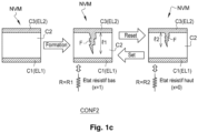
- FIG. 1c illustrates a sectional view of the memory component NVM according to the second operating configuration CONF2 corresponding to operation in resistive memory with variable conductive filament (ReRAM or OxRAM). Operation according to the second configuration CONF2 requires the formation of a conductive filament F through at least a part of the central layer C2, electrically insulating.
- RERAM resistive memory with variable conductive filament
- the memory component NVM is a structure of the MIM type (metal, insulator, metal) having an infinite resistance between the two electrodes EL1 and EL2.
- the filament F In order to configure the memory component NVM according to the second operating configuration CONF2 in resistive memory, it is necessary to form the filament F starting from the upper electrode EL2 through at least part of the volume of the central layer C2.
- the formation of the filament makes it possible to obtain a variable resistance by modulating the length I of the conductive filament formed.
- an electric formation voltage is applied to the upper electrode EL2.
- the electrical formation voltage has a sufficiently high amplitude and/or duration to cause the generation of oxygen vacancies in the central layer C2.
- the electrical formation voltage applied must exceed a predetermined value so as to tear off oxygen ions from the crystal lattice of the central metal oxide layer which will merge towards the upper electrode EL2 thus forming a conductive filament F through the layer central consisting of oxygen vacancies.
- the behavior of a resistive element is obtained at a variable resistance R according to the length I of the conductive filament F.
- a positive electrical voltage is applied to the lower electrode EL1
- the reverse reaction takes place and oxygen ions will come to fill part of the oxygen vacancies forming the conductive filament. This results in a reduction in the length of the conductive filament.
- the resistance of the resistive element increases.
- the length of the conductive filament F increases by the same mechanism described for the wire forming operation.
- the resistance of the resistive element decreases. This is referred to as a low resistive state and a SET type write operation.
- Reading an NVM memory component during operation according to the second configuration CONF2 consists of estimating the resistance between the upper electrode and the lower electrode and comparing it with a threshold value to determine whether the resistive state is a high state or low.
- the voltage applied is determined by an amplitude of this voltage and a duration of application of this voltage.
- the voltage applied during the formation of the filament has the highest duration of application and/or amplitude among the various voltages mentioned above because it requires the tearing of the oxygen atoms from the crystal lattice of the central layer C2.
- the write voltage compatible with the second configuration CONF2 (during a SET or RESET operation), has an application duration and/or an amplitude lower than those used for the formation of the filament since it acts partially on the previously formed filament.
- the write voltage compatible with the first configuration CONF1 has lower power consumption than the write voltage compatible with the second configuration because it is a modification of the ferroelectric characteristics (we act on electrons) and not a structural modification at the atomic scale.
- write and formation voltages are chosen in the form of square pulses defined by an amplitude and an application duration.
- the formation voltage of the filament typically has an amplitude between 3V and 4V for a duration of 5 ⁇ s to 25 ⁇ s.
- the write voltage compatible with the second configuration CONF 2 has an amplitude of between 1.7V and 2.5V for a duration of 100ns.
- the write voltage compatible with the first configuration CONF1 typically has an amplitude of 2V to 5V for a duration of 5ns to 100ns.
- the intensity of the current traversing the memory structure NVM configured according to the first configuration CONF1 is lower than the intensity of the current traversing the memory structure NVM configured according to the second configuration CONF2 (resistive behavior).
- CONF1 and CONF2 have complementary characteristics in terms of technological robustness of the memory component and energy consumption faced with a considerable number of writes or reads:
- the write operation according to the second operating configuration CONF2 is based on a structural physical modification of the central layer C2 implementing high current intensities, typically order of 100 ⁇ A.
- the second operating configuration CONF2 requires at each write a significant energy necessary for this structural modification of the material (approximately 100 pJ/bit).
- the write operations according to the first operating configuration CONF1 consist more simply of applying an electric voltage to the terminals of the central layer C2 (approximately 10fJ/bit). In this case, the write operation implements lower current intensities.
- the first operating configuration CONF1 consumes less write energy than the second operating configuration CONF2 with a write energy saving ratio per bit of up to 10000.
- the repetition of the write operations according to the second operating configuration CONF2 generates repetitive modifications of the internal structure of the central layer C2 which leads to progressive material wear of the NVM memory structures.
- the number of write cycles before the failure of a memory component operating solely according to the second configuration CONF2 is evaluated is estimated at a value comprised between 10 5 cycles and 10 6 cycles.
- the wear mechanism is linked to the charge injection mechanisms.
- the number of write cycles before the failure of a memory component operating only according to the first configuration CONF1 is estimated at 10 12 cycles.
- the data is stored in the resistive state of the device.
- the read operation therefore consists of a simple evaluation of this electrical quantity without modifying the physical state of the component.
- reading does not degrade the stored data or the hardware structure of the memory component which, in this operating configuration, has an almost infinite reading endurance in the application context of a computer.
- the read operation is destructive of the content stored in the memory component NVM operating according to the first configuration CONF1.
- the reading process consists in evacuating the quantity of charges which traverse the dielectric during a switching. This results in the need for a rewrite operation following the reading of stored data.
- write endurance which is not infinite, is transferred to read endurance since each read involves a rewrite.
- the first operating configuration CONF1 of the memory component NVM is more suitable for a calculation phase presenting a considerable number of memory write operations.
- the second operating configuration CONF2 of the memory component NVM is more suited to a calculation phase presenting a considerable number of memory read operations.
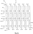
- FIG. 2a illustrates an array of memory cells 100 comprising the memory component NVM according to the invention.
- the matrix of memory cells 100 comprises for each line L i a first input node WL ⁇ i> configured to receive a selection signal VWL ⁇ i>.
- the array of memory cells 100 further comprises for each column C j a second input node SL ⁇ j> configured to receive a first write voltage VSL ⁇ j>.
- the array of memory cells 100 further comprises for each column C j an input/output node BL ⁇ j> configured to receive a second write voltage VBL ⁇ j> and supply a read voltage VBL ⁇ j>.
- Each memory cell BC ij of the matrix 100 comprises a configurable and non-volatile memory component NVM and a selection transistor T1.
- the selection transistor T1 has a gate connected to the first input node WL ⁇ i> associated with the row of said memory cell BC ij .
- Transistor T1 connects lower electrode EL1 to input/output node BL ⁇ j> associated with the column of said memory cell BC ij .
- the upper electrode EL2 of the memory component NVM of each memory cell BC ij is connected to the input node SL ⁇ j> associated with the column of said memory cell BC ij .
- each access to the memory cell BC ij in write or read mode, consists in selecting a line by activating the transistor T1 via the selection signal VWL ⁇ i> and applying to the pair of nodes (SL ⁇ j> , BL ⁇ j>) the voltages and/or currents needed to modify or probe the saved data.
- the invention remains applicable for other memory cell array architectures.
- the pair of signals (WL ⁇ j>, BL ⁇ j>) describing the two dimensions of the plane is sufficient to select a memory cell BC ij of the matrix in reading or in writing.
- This implementation of the memory cell matrix makes it possible to reduce the surface occupied by the matrix while being compatible with operation according to the two operating configurations requiring direct access to the electrodes EL1 and EL2 of each component.
- a compact 1R1T or 1C1T type cell is thus obtained depending on the operating configuration chosen.
- FIG. 2b illustrates an electrical modeling of a memory cell of the matrix according to the invention according to the first operating configuration CONF1.
- the memory component NVM behaves like a capacitive element exhibiting a variable capacitance according to the direction of the electric polarization of the central layer C2.
- the memory cell BC ij is thus modeled by a compact architecture 1C1T with a direct action on the electrodes EL1 and EL2 of the capacitive element when the transistor T1 is in the on state.
- FIG. 2c illustrates an electrical modeling of a memory cell of the matrix according to the invention according to the second operating configuration CONF2.
- the memory component NVM behaves like a resistive element having a variable resistance according to the length of the conductive filament through the central layer C2.
- the memory cell BC ij is thus modeled by a compact 1R1T architecture with a direct action on the electrodes EL1 and EL2 of the capacitive element when the transistor T1 is in the on state.
- the transistors T1 are dimensioned to obtain a saturation current sufficient to supply the high electric currents associated with the resistive operation of the memory cells BC ij when the second operating configuration CONF2 is chosen.
- FIG. 3 illustrates a block diagram of the architecture of a data storage circuit 10 comprising the array of memory cells 100 according to the invention.
- the storage circuit 10 is intended to be implemented in an algorithm execution computer having two operating phases such that the first configuration requires a large number of write operations (or update) of the data stored by the storage circuit 10 and such that the second configuration requires a large number of operations for reading said data.
- the data storage circuit 10 comprises a write circuit CW, the matrix of memory cells 100 (of dimensions NxM) intended to store calculation data, a read circuit CL, at least one intermediate storage memory MEM_INT and means of control CONT.
- the write circuit CW is configured to write in each memory cell BC ij by supplying the first and/or the second write voltage VSL ⁇ j>, VBL ⁇ j> from a write control signal cont_w ⁇ j>.
- Each of the write voltages VSL ⁇ j>, VBL ⁇ j> can be adapted according to the operating configuration chosen from CONF1 or CONF2.
- the write circuit CW is configured in such a way as to supply the memory component with a write voltage compatible with the first operating configuration CONF1 requiring a write energy lower than that of the write operation when the second operating configuration CONF2 is chosen.
- the control signals cont_w ⁇ 1:M> are supplied to the write circuit CW through a bus of width equal to the number of columns M of the cell matrix memory 100 in order to be able to write simultaneously on the memory cells BC ij of a line L i selected following the activation of a predetermined selection signal VWL i .
- the read circuit CL comprises a plurality of elementary read circuits CL ⁇ j>, which are configured to supply a signal for reading the stored data (x(fe) ij or x(ox) ij ) for each memory cell according to the result of comparison of the read voltage VBL ⁇ j> with a predetermined reference voltage VREF.
- the read voltage applied to the node BL ⁇ j> is in the form of a pulse.
- the reference signal VREF is generated by an external voltage source not presented for the sake of simplification. It is conceivable to determine the value of the reference voltage according to the operating configuration chosen to adapt the threshold which determines the logic state of the data item stored in read mode.
- Each elementary read circuit CL ⁇ j> is associated with a column of the matrix of memory cells of the same rank and it is connected to the input/output node BL ⁇ j> of the corresponding column. This makes it possible to simultaneously read the memory cells BC ij of a row L i selected following the activation of a predetermined selection signal VWL i .
- the control means CONT are intended to control the elementary read circuits CL ⁇ j> and the write circuit CW according to the chosen operating configuration.
- the control means CONT generate control signals cont_w ⁇ 1:M> to the write circuit CW so as to adapt the amplitude and/or the duration of the write voltages according to the chosen operating configuration.
- the first operating configuration CONF1 requires less write energy than the second configuration CONF2.
- control means CONT are intended to supply the plurality of selection signals VWL ⁇ 1:N> to the selection nodes WL ⁇ 1:N> so as to choose a single line L i during an operation of reading or writing.
- the intermediate storage memories MEM_INT are arranged such that each intermediate storage memory MEM_INT is intended to temporarily store each read signal supplied by an elementary read circuit CL ⁇ j> CL for each read cycle.
- the temporary storage memories can be made by any type of memories capable of performing this function such as registers, synchronous flip-flops, asynchronous flip-flops and memory strips without limitation.
- control means CONT are also intended to control the transition from the first configuration CONF1 to the second configuration CONF2 or vice versa from the data stored in the internal storage memories MEM_INT.
- the control means CONT comprise a conversion circuit CONV configured to convert, for each memory cell, the read signal x(fe) ij resulting from the first operating configuration CONF1 into a write control signal CONT_W ⁇ j> compatible with the second operating configuration CONF2.
- the conversion circuit CONV is configured to convert, for each memory cell, the read signal x(ox) ij resulting from the second operating configuration CONF2 into a write control signal CONT_W ⁇ j> compatible with the first operating configuration CONF1.
- the conversion circuit CONV is used to translate the logic content of the memory cells of the matrix 100 according to a starting operating configuration to write control signals making it possible to generate compatible write voltages in terms of power d writing with the target operating configuration.
- FIG. 4a illustrates a first example of the control of the operating configuration of the memory cells of a data storage circuit according to the invention according to the calculation phase executed.
- the execution of the calculation algorithm by the computer circuit begins with the first calculation phase PH1 composed of several iterations for updating the data stored in the storage circuit 10.
- the data storage circuit 10 is configured by the CONT control means to operate according to the first operating configuration CONF1 more compatible with a considerable number of writes in the memory cells BC ij .
- each memory component NVM of the matrix 100 undergoes a plurality of operations for changing the direction of the polarization by receiving positive write voltages on the upper electrode EL2 or lower electrode EL1.
- the write voltages applied by the write circuit are square pulses of duration ⁇ T1.
- the data storage circuit 10 receives an instruction from the computer circuit to inform it of the transition from the first calculation phase Ph1 to the second calculation phase Ph2 .
- the control means CONT of the data storage circuit 10 trigger a transition phase Ph 1 ⁇ 2 from the first operating configuration CONF1 to the second operating configuration CONF2.
- the Ph 1 transition phase ⁇ 2 consists of several iterations of steps repeated for each line L i of the matrix of memory cells 100.
- the first step consists in selecting the line of the matrix of memory cells 100 by activating the corresponding selection signal VWL ⁇ i>. This step is carried out by the control means CONT by activating the selection transistors T1 of the cells of the line L i .
- the second step consists in reading the M memory cells BC ij of the row selected by the M elementary read circuits CL ⁇ j> arranged at the bottom of each column of the matrix.
- Each read signal x(fe) ij is stored in the intermediate storage memory MEM_INT connected to the output of the elementary read circuit CL ⁇ j>.
- the third step consists in applying to each second input node SL ⁇ j> of said line an electric formation voltage in order to form a conductive filament in the second layer C2 starting from the third layer C3 in each memory cell BC ij .
- the control means CONT configure the write circuit to apply an electric formation voltage in the form of a square pulse over a duration ⁇ T2 long enough to create oxygen vacancies in the central layer.
- the duration ⁇ T2 is 1000 times greater than the duration ⁇ T1 to change the internal structure of the central layer C2.
- a formation of the conductive filament is thus obtained in all the memory components of the line L i .
- the memory cells, where the filament has been formed are then initialized to a low resistive state (LRS).
- LLS low resistive state
- the fourth step consists in converting the read signals x(fe) ij stored in the intermediate storage memories MEM_INT during operation according to the first configuration CONF1 to write control signals compatible with the second configuration CONF2.
- This step is carried out by the converter circuit CONV which carries out the translation of the logic content of the memory cells of the line L i according to the starting operating configuration to write control signals making it possible to generate write voltages compatible in terms of write energy with the operating configuration CONF2.
- the fifth step consists in writing in the memory cells of said line according to the write control signals compatible with the second configuration CONF2 so as to vary the length of the conductive filament formed.
- the write circuit CW is configured to generate write voltages in the form of a square pulse over a duration ⁇ T3 greater than the duration ⁇ T1 of the write signal compatible with the first configuration CONF1 and less than the duration ⁇ T2 of the filament formation voltage.
- the sequence described is repeated for all the rows of the matrix 100 until the transfer of the stored data from the first configuration CONF1 to the second configuration CONF2 is finalized.
- the storage circuit operates according to the second configuration CONF2 compatible with the execution by the computer of the second phase of calculation Ph2 presenting a considerable number of operations for reading the matrix 100.
- the circuits of CL readings are suitable for measuring resistance variations in NVM memory components and no longer a variation in the amount of charge.
- the data storage circuit 10 receives an instruction from the computer circuit to inform it of the transition from the second calculation phase Ph2 to the first calculation phase Ph1.
- the control means CONT of the data storage circuit 10 trigger a transition phase Ph 2 ⁇ 1 from the second operating configuration CONF2 to the first operating configuration CONF1. During this transition the conductive filament is not destroyed because the formation of the filament is irreversible.
- the Ph 2 transition phase ⁇ 1 consists of several iterations of steps repeated for each line L i of the matrix of memory cells 100.
- the first step consists in selecting the line of the matrix of memory cells 100 by activating the corresponding selection signal VWL ⁇ i>. This step is carried out by the control means CONT by activating the selection transistors T1 of the cells of the line L i .
- the second step consists in reading the M memory cells BC ij of the row selected by the M reading circuits CL arranged at the bottom of each column of the matrix.
- Each read signal x(ox) ij is stored in the intermediate storage memory MEM_INT connected to the output of the elementary read circuit CL ⁇ j>.
- the third step consists in applying to each second input node SL ⁇ j> of said line a reset electric voltage on the lower electrode EL1 (RESET operation) so as to reduce the length of the filament.
- RESET operation reset electric voltage on the lower electrode EL1
- a data conversion step by the conversion circuit CONV by reading in the intermediate storage memories MEM_INT is carried out in a manner similar to the transition phase Ph 1 ⁇ 2 but with a translation in the opposite direction.
- the storage circuit 10 operates according to the first configuration CONF1 compatible with the execution by the calculator of the first phase of calculation Ph1 having a considerable number of write operations of the matrix 100.
- the read circuits CL are adapted to measure variations in the quantity of charge in the memory components NVM as explained above so as to exploit polarization variations and ignore the existence of the conductive filament.
- the electrical formation voltage during a transition phase Ph 1 ⁇ 2 , and the reset electrical voltage during a transition phase Ph 2 ⁇ 1 are referred to by the term “transformation voltage”.
- FIG. 4b illustrates a second example of the control of the operating configuration of the memory cells of a data storage circuit according to the invention according to the calculation phase executed.
- the high resistive state corresponds to a resistance greater than 10 MOhm and the low resistive state corresponds to a resistance less than 5 kOhm.
- FIG. 5a illustrates a read mechanism according to the first operating configuration CONF1 produced by a first embodiment of the read circuit.
- the electrical diagram (50) shows a memory cell BC ij in capacitive operation with an elementary read circuit CL ⁇ j> composed of a comparator circuit COMP.
- the comparator COMP receives on a first input a reference voltage VREF and on a second input the read voltage VBL ⁇ j> through the transistor T1 set to the on state.
- the comparator circuit COMP comprises an output to supply the binary read signal x(fe) ij according to the result of the comparison.
- the reference signal VREF is generated by an external voltage source not presented for the sake of simplification.
- parasitic capacitance C BL which is used to receive the charges supplied by the memory component NVM during reading.
- the voltage at the terminals of the parasitic capacitance C BL is proportional to the quantity of charge supplied by the capacitive component NVM during the read operation.
- Diagram 51 shows the variation over time of the various electrical signals involved in the read operation according to the first operating configuration CONF1.
- the procedure for reading the memory cell consists in charging the node BL ⁇ j> by applying a voltage to the node SL ⁇ j>, and therefore through the memory cell BC ij having a capacitive behavior.
- the first step consists in selecting the memory cell to be read by turning on the selection transistor (T1) corresponding to said memory cell.
- the read node BL ⁇ j> associated with the memory cell BC ij is initialized at a zero voltage by the write circuit CW. This corresponds to the initial state of the read circuit at time t0 of diagram 51.
- a read pulse is applied to the second input node SL ⁇ j> associated with said column in order to charge the node with input/output BL ⁇ j> associated with the same column.
- FIG. 5b illustrates a read mechanism according to the second operating configuration CONF2 produced by the first embodiment of the read circuit described in the figure 5b .
- the electrical diagram 50' shows a memory cell BC ij in resistive operation with an elementary read circuit CL ⁇ j> composed of a comparator circuit COMP.
- Diagram 51' shows the variation over time of the various electrical signals involved in the read operation according to the second operating configuration CONF2.
- the first step consists in selecting the memory cell to be read by turning on the selection transistor T1 corresponding to said memory cell.
- the read node BL ⁇ j> associated with the memory cell BC ij is initialized at a zero voltage by the write circuit CW. This corresponds to the initial state of the read circuit at time t0 of diagram 51'.
- a read pulse is applied to the second input node SL ⁇ j> associated with said column in order to charge the input/output node BL ⁇ j> associated with the same column.
- Reading the memory cell consists of estimating the resistance value of the NVM device.
- the equivalent circuit obtained when the transistor T1 is on is an RC circuit formed by the resistance of the memory component NVM in series with the parasitic capacitive element C BL.
- a slower evolution of the voltage BL ⁇ j> is thus observed with a greater time constant ⁇ when the memory component has a high resistive state (HRS).
- HRS high resistive state
- LRS low resistive state
- the duration of the applied pulse must be short enough to probe the voltage BL ⁇ j> during the transient state and avoid reaching the stationary state of the load of the capacitive element C BL .
- FIG 5c illustrates a second embodiment of the elementary read circuit CL ⁇ j> compatible with the second operating configuration.
- the reading circuit illustrated in the figure 5c differs from that of the figure 5b by the addition in the elementary read circuit CL ⁇ j> of a read resistor R lect connected in parallel with the capacitive element C BL.
- the read resistor R lect makes it possible to produce a voltage divider bridge such that the static value of the voltage of VBL ⁇ j> (steady state) varies with the value of the resistance of the memory component NVM, behaving like a variable resistor according to the value of the stored data.
- This alternative eliminates the constraint of having a short read pulse. In fact, there is no longer any need to compare the voltages during the transient state since the static value of VBL ⁇ j> depends on the division ratio of the voltage divider bridge produced by read resistor R lect and the memory component NVM.
- FIG 6a illustrates a combined embodiment of the read circuit CL and of an intermediate storage memory MEM_INT according to the invention. This is an embodiment where the read circuit CL and the intermediate storage memory MEM_INT which is associated with it are made in a single circuit CL+MEM_INT called “detection and storage circuit”.
- the detection and storage circuit CL+MEM_INT comprises a latch latch LATCH having two input/output nodes N'1 and N'2; a first input node N1 intended to receive the reference voltage VREF and connected to the first input/output node N1' of the latch flip-flop through a first switch I1; and a second input node N2 intended to receive the read voltage VBL ⁇ j> and connected to the second input/output node N2' of the latch flip-flop through a second switch I2.
- Latch flip-flop LATCH consists of two inverter circuits INV1 and INV2 connected head-to-tail such that the output of each feeds the input of the other. One then obtains an operation in intermediate memory at the steady state of the LATCH latch toggle. This is possible when each of the two nodes N1' and N2' to be compared is connected to each of the inputs-outputs of the inverters. In transient state, the application of two different voltages on the two nodes N1' and N2' disturbs the state of equilibrium of the LATCH latch flip-flop which switches to a new state of equilibrium according to the comparison between the two different voltages applied to the nodes N1' and N2'.
- the two inverter circuits INV1 and INV2 are connected to a power supply node NVDD through a first control transistor T cmd1 .
- the two inverter circuits INV1 and INV2 are connected to an electrical ground node through a second control transistor T cmd2 .
- the inverter circuits INV1 and INV2 are supplied by the supply voltage VDD.
- the inverter circuits INV1 and INV2 are isolated from the supply voltage VDD and therefore the latch flip-flop LATCH is deactivated.
- the first step consists in putting the first switch I1 and the second switch I2 in a blocking state in order to isolate the latch flip-flop LATCH.
- the second step consists in the selection by the control means CONT of the memory cell to be read by activating the selection transistor T1 corresponding to said memory cell.
- the third step consists of initializing the input/output node BL ⁇ j> associated with said column at zero voltage by the write circuit CW.
- the fourth step consists in the application by the write circuit CW of a read voltage, in the form of a pulse for example, on the second input node SL ⁇ j> associated with said column.
- This step makes it possible to precharge the input/output node BL ⁇ j> with read voltage.
- the first and the second switch I1 and I2 are set to an on state, and the first and the second control node T cmd1 and T cmd2 are set to the state blocking. This disables the LATCH latch flip-flop to allow nodes N1' and N2' to be precharged with the read voltage.
- the first and second switches I1 and I2 are turned on and the first and second control nodes T cmd1 and T cmd2 are turned on to activate the latch flip-flop LATCH.
- the voltages previously preloaded on the nodes N1' and N2' disturb the balance of the LATCH latch flip-flop. This disturbance triggers a comparison mechanism between the read voltage VBL ⁇ j> on the node N2' with the reference voltage VREF on the node N1'.
- the latch flip-flop LATCH finds a state of equilibrium by switching according to the comparison between the two voltages VREF and VBL ⁇ j>.
- the detection and storage circuit CL+MEM_INT thus performs the comparator circuit function in the context of a read operation.
- the final step consists of putting the first and the second switches I1 and I2 in a blocking state in order to isolate the latch from its environment and thus temporarily store the read signal according to the state of the pair of nodes N1' and N2' resulting from the comparison operation.
- the detection and storage circuit CL+MEM_INT thus performs the temporary storage function usable for the conversion during a phase of transition from one operating configuration to another.
- the advantage of this embodiment consists in a reduction of the surface occupied by the circuit compared to an implementation with a read circuit CL and temporary storage memories MEM_INT produced by two distinct circuits.
- FIG. 6b illustrates a read and store mechanism according to the second operating configuration implemented by the combined circuit CR+MEM_INT of the figure 6a .
- the second input node N2 intended to receive the read voltage VBL ⁇ j> is connected to a constant current source GEN generating a read current I lect .
- the read current I lect travels the resistive element corresponding to the memory component NVM when the latter operates according to the second operating configuration CONF2.
- the current source GEN can be produced by a current mirror which can be activated or deactivated according to control signals not shown for the sake of simplification.
- the fourth step consists of upon activation of the current mirror GEN so as to supply an electric current at a predetermined intensity flowing through the resistive element NVM with the switches I1 and I2 in an on state and the power supply to the two inverters INV1 and INV2 cut off. This makes it possible to precharge the node N2' to a potential corresponding to the voltage drop caused by the resistance of the resistive element NVM.
- the duration of this step is predetermined by the designer so as to reach steady state on the node N2'. The duration is of the order of a few tens of nanoseconds.
- the fifth step consists in activating the power supply to the inverters INV1 and INV2 and therefore activating the latch switch LATCH while simultaneously setting the switches I1 and I2 to a blocking state so as to isolate the latch switch LATCH from the node N2.
- the outputs (N1', N2') of the LATCH latch flip-flop therefore switch to a high or low logic state without loading or unloading the node N2. From a consumption point of view, this has the advantage of limiting the variations of the voltage V SL on the upper electrode of the memory component NVM.
- Artificial neural networks are computational models that mimic the functioning of biological neural networks. Artificial neural networks include neurons interconnected by synapses, each synapse is attached to a synaptic weight (or synaptic coefficient) implemented for example by digital memories.
- neural networks In the context of embedded artificial intelligence, electronic chips implementing neural networks (deep and/or impulse) require a large memory capacity to store the parameters of these networks.
- the implementation of neural networks can be broken down into two phases: learning and inference.
- the learning phase consists in modifying the synaptic weights of the network according to a so-called learning algorithm to make them converge towards values such that the network accomplishes the task for which it is trained.
- the inference phase consists of applying the previously learned task to the input data.
- the data storage circuit 10 is configured according to the first operating configuration CONF1 when during the execution of a learning phase (intensive writing) by the artificial neural network.
- the data storage circuit 10 is configured according to the second operating configuration CONF2 when during the execution of an inference phase (intensive reading) by the artificial neural network.
- This implementation of the data storage circuit 10 according to the invention makes it possible to improve the technological robustness, the reliability and the energy consumption of the neural network computer circuit by adapting the storage means with the constraints of the calculation phase carried out during the life of the computer circuit.
Landscapes
- Engineering & Computer Science (AREA)
- Computer Hardware Design (AREA)
- Physics & Mathematics (AREA)
- Theoretical Computer Science (AREA)
- Biomedical Technology (AREA)
- Biophysics (AREA)
- Health & Medical Sciences (AREA)
- Life Sciences & Earth Sciences (AREA)
- Data Mining & Analysis (AREA)
- General Physics & Mathematics (AREA)
- Software Systems (AREA)
- Computational Linguistics (AREA)
- Mathematical Physics (AREA)
- Evolutionary Computation (AREA)
- General Health & Medical Sciences (AREA)
- Molecular Biology (AREA)
- Computing Systems (AREA)
- General Engineering & Computer Science (AREA)
- Artificial Intelligence (AREA)
- Neurology (AREA)
- Materials Engineering (AREA)
- Power Engineering (AREA)
- Chemical & Material Sciences (AREA)
- Semiconductor Memories (AREA)
Abstract
Un circuit de stockage de données comporte une matrice de cellules mémoire qui sont configurables et non volatiles (NVM), chacune cellule étant destinée à fonctionner selon l'une quelconque parmi deux configurations de fonctionnement, la première configuration de fonctionnement (CONF1) correspondant à une mémoire ferroélectrique à polarisation électrique variable et la seconde configuration de fonctionnement (CONF2) correspondant une mémoire résistive à filament conducteur variable. Chaque cellule mémoire comprend une première couche (C1) en un matériau électriquement conducteur formant une électrode inférieure (EL1), une seconde couche (C2) en un matériau diélectrique et ferroélectrique, et une troisième couche (C3) en matériau électriquement conducteur formant une électrode supérieure (EL2).A data storage circuit comprises an array of memory cells which are configurable and non-volatile (NVM), each cell being intended to operate according to any one of two operating configurations, the first operating configuration (CONF1) corresponding to a ferroelectric memory with variable electrical bias and the second operating configuration (CONF2) corresponding to a resistive memory with variable conductive filament. Each memory cell comprises a first layer (C1) of an electrically conductive material forming a lower electrode (EL1), a second layer (C2) of a dielectric and ferroelectric material, and a third layer (C3) of electrically conductive material forming an electrode upper (EL2).
Description
L'invention concerne généralement des cellules mémoires non volatiles configurables pour stocker des données manipulées par des calculateurs pour exécuter un algorithme de calcul. L'algorithme de calcul exécuté nécessite un nombre considérable d'opérations d'écriture et/ou de lecture dans les cellules mémoires selon l'invention.The invention generally relates to configurable non-volatile memory cells for storing data manipulated by computers to execute a calculation algorithm. The calculation algorithm executed requires a considerable number of write and/or read operations in the memory cells according to the invention.
Dans le domaine des calculateurs embarqués exécutant un algorithme de calcul impliquant un nombre grandissant de variables numériques, les puces électroniques nécessitent une importante capacité mémoire pour stocker les variables de calcul. Ces algorithmes de calcul peuvent implémenter plusieurs phases de calcul : une première phase au cours de laquelle les variables manipulées subissent de nombreuses modifications et une seconde phase au cours de laquelle les mêmes variables sont figées ou subissent peu de modifications.In the field of on-board computers executing a calculation algorithm involving an increasing number of digital variables, electronic chips require a large memory capacity to store the calculation variables. These calculation algorithms can implement several calculation phases: a first phase during which the manipulated variables undergo numerous modifications and a second phase during which the same variables are frozen or undergo few modifications.
Différents types de mémoires non volatiles peuvent être utilisés pour réaliser les moyens de stockage des variables de calcul d'un circuit calculateur. Cependant, les différentes technologies de mémoires non-volatiles présentent des caractéristiques différentes de fiabilité et de robustesse face à un nombre considérable d'opérations de lecture et d'écriture subies. Pour qualifier la robustesse des différentes technologies de mémoires, on définit les caractéristiques suivantes :
- On entend par « cyclabilité en écriture » le nombre maximal de cycles d'écriture subis par une cellule mémoire avant sa défaillance structurelle. Il s'agit alors d'un critère de caractérisation de la robustesse technologique des cellules mémoire face à un nombre intense d'opérations d'écriture ;
- On entend par « endurance en lecture » le nombre maximal de cycles de lecture subis par une cellule mémoire avant sa défaillance structurelle. Il s'agit alors d'un critère de caractérisation de la robustesse technologique des cellules mémoire face à un nombre intense d'opérations de lecture ;
- On entend par « énergie de lecture » l'énergie nécessaire pour lire un bit de la cellule mémoire ; elle s'exprime en Joule par bit. Il s'agit alors d'un critère de caractérisation de la performance énergétique des cellules mémoire lors de la réalisation d'une opération de lecture ;
- On entend par « énergie d'écriture » l'énergie nécessaire pour écrire un bit de la cellule mémoire; elle s'exprime en Joule par bit. Il s'agit alors d'un critère de caractérisation de la performance énergétique des cellules mémoire lors de la réalisation d'une opération d'écriture.
- “Write cyclability” means the maximum number of write cycles undergone by a memory cell before its structural failure. This is then a criterion for characterizing the technological robustness of memory cells in the face of an intense number of write operations;
- By “read endurance” is meant the maximum number of read cycles undergone by a memory cell before its structural failure. This is then a criterion for characterizing the technological robustness of memory cells in the face of an intense number of read operations;
- “Read energy” means the energy required to read a bit from the memory cell; it is expressed in Joule per bit. This is then a criterion for characterizing the energy performance of the memory cells during the performance of a read operation;
- “Write energy” means the energy required to write a bit of the memory cell; it is expressed in Joule per bit. This is then a criterion for characterizing the energy performance of memory cells during the performance of a write operation.
L'augmentation considérable du nombre d'opérations de lecture et d'écriture pour implémenter les algorithmes de calcul est très énergivore pour un système dédié à une application mobile (téléphonie, véhicule autonome, robotique..). Il existe donc un besoin pour des calculateurs permettant de satisfaire aux contraintes des systèmes embarqués et des applications visées.The considerable increase in the number of read and write operations to implement the calculation algorithms is very energy-intensive for a system dedicated to a mobile application (telephony, autonomous vehicle, robotics, etc.). There is therefore a need for computers making it possible to satisfy the constraints of the on-board systems and of the targeted applications.
Dans ce contexte, un problème technique à résoudre est l'amélioration de la performance énergétique et de la robustesse technologique des moyens de stockages pour un circuit calculateur apte à réaliser une première phase de fonctionnement nécessitant un grand nombre d'opérations d'écriture dans les moyens de stockage et apte à réaliser une seconde phase de fonctionnement nécessitant un grand nombre d'opérations de lecture desdits moyens de stockage.In this context, a technical problem to be solved is the improvement of the energy performance and the technological robustness of the storage means for a computer circuit able to carry out a first phase of operation requiring a large number of write operations in the storage means and capable of carrying out a second phase of operation requiring a large number of reading operations of said storage means.
La publication scientifique intitulée « Interplay between ferroelectric and resistive switching in doped crystalline HfO2» de Max et al décrit un composant mémoire compatible avec un fonctionnement en mémoire résistive à filament et un fonctionnement en mémoire ferroélectrique. La publication se limite à décrire le composant mémoire d'un point de vue physique en tant que composant élémentaire. La publication ne présente pas une implémentation spécifique dans un circuit de stockage de données embarqué dans un circuit calculateur configurable selon les spécificités de la phase de calcul réalisée en matière de nombre d'opérations de lecture et d'écriture.The scientific publication entitled "Interplay between ferroelectric and resistive switching in doped crystalline HfO2" by Max et al describes a memory component compatible with resistive filament memory operation and ferroelectric memory operation. The publication is limited to describing the memory component from a physical point of view as an elementary component. The publication does not present a specific implementation in a data storage circuit embedded in a configurable computer circuit according to the specifics of the calculation phase carried out in terms of the number of read and write operations.
Pour répondre au problème technique lié à l'amélioration de la performance énergétique et de la robustesse technologique des moyens de stockages d'un circuit calculateur destiné à exécuter un algorithme de calcul sur des données numériques, l'invention propose un circuit de stockage de données comprenant une matrice de cellules mémoire non volatiles et configurables selon deux configurations de fonctionnement. La première configuration correspond à un fonctionnement en mémoire ferroélectrique à polarisation électrique variable (FeRAM) et la seconde configuration correspond à un fonctionnement en mémoire résistive à filament conducteur variable (OxRAM ou ReRAM). En effet, d'une part la technologie de mémoires ferroélectriques à polarisation électrique variable (FeRAM) présente une forte endurance en écriture et une basse énergie d'écriture le rendant plus adapté pour réaliser une opération nécessitant plusieurs itérations d'écriture des données stockées. D'autre part, la technologie de mémoires résistive à filament conducteur variable (OxRAM ou ReRAM) présente une forte endurance en lecture et une basse énergie en lecture le rendant plus performant pour réaliser une opération de calcul nécessitant un nombre considérable de lectures des données stockées .To answer the technical problem related to the improvement of the energy performance and the technological robustness of the means of storage of a circuit computer intended to execute a calculation algorithm on digital data, the invention proposes a data storage circuit comprising a matrix of non-volatile memory cells and configurable according to two operating configurations. The first configuration corresponds to operation in ferroelectric memory with variable electrical bias (FeRAM) and the second configuration corresponds to operation in resistive memory with variable conductive filament (OxRAM or ReRAM). Indeed, on the one hand, the technology of ferroelectric memories with variable electrical polarization (FeRAM) has high write endurance and low write energy, making it more suitable for carrying out an operation requiring several iterations of writing the stored data. On the other hand, resistive memory technology with variable conductive filament (OxRAM or ReRAM) has high read endurance and low read energy making it more efficient to perform a calculation operation requiring a considerable number of readings of the stored data. .
Les cellules mémoires selon l'invention sont réalisées par le même empilement de couches minces sur un même substrat semiconducteur pour les deux configurations de fonctionnement permettant une implémentation dense des cellules mémoires à technologie hybride dans le même plan mémoire. Cela offre l'avantage d'une réduction de la surface du circuit de stockage de données tout en ayant un fonctionnement adaptable selon la phase exécutée par le calculateur en terme de prépondérance du nombre d'opérations de lecture ou d'écriture.The memory cells according to the invention are produced by the same stack of thin layers on the same semiconductor substrate for the two operating configurations allowing a dense implementation of memory cells with hybrid technology in the same memory plane. This offers the advantage of a reduction in the surface of the data storage circuit while having an adaptable operation according to the phase executed by the computer in terms of preponderance of the number of read or write operations.
L'invention propose en outre un procédé de commande permettant de configurer le passage de la première configuration à la seconde configuration des cellules mémoires de manière à convertir les données stockées selon la configuration ferroélectrique à des données stockées selon la configuration résistive.The invention further proposes a control method making it possible to configure the passage from the first configuration to the second configuration of the memory cells so as to convert the data stored according to the ferroelectric configuration to data stored according to the resistive configuration.
Enfin, nous allons décrire l'invention dans le contexte applicatif d'un réseau de neurones artificiels à titre illustratif sans perte de généralité. Les caractéristiques de l'invention restent valables pour tout calculateur d'exécution d'algorithmes présentant deux phases de fonctionnement tel que la première configuration nécessite un nombre important d'opérations d'écriture (ou mise à jour) des données stockées et tel que la seconde configuration nécessite un nombre important d'opérations de lecture desdites données.Finally, we will describe the invention in the application context of an artificial neural network by way of illustration without loss of generality. The characteristics of the invention remain valid for any algorithm execution computer having two operating phases such that the first configuration requires a large number of write (or update) operations of the stored data and such that the second configuration requires a large number of operations for reading said data.
L'invention a pour objet un circuit de stockage de données comprenant une matrice de cellules mémoire, de N lignes et M colonnes réalisée sur un substrat semi-conducteur, comprenant :
- Pour chaque ligne un premier nœud d'entrée configuré pour recevoir un signal de sélection ;
- au moins un second nœud d'entrée configuré pour recevoir une première tension d'écriture ;
- Pour chaque colonne un nœud d'entrée/sortie configuré pour recevoir une seconde tension d'écriture et fournir une tension de lecture ;
- les cellules mémoire étant configurables et non volatiles ; chacune étant destinée à fonctionner selon l'une quelconque parmi deux configurations de fonctionnement ; la première configuration de fonctionnement correspondant à une mémoire ferroélectrique à polarisation électrique variable ; et la seconde configuration de fonctionnement correspondant une mémoire résistive à filament conducteur variable ;
- un empilement de couches minces selon l'ordre suivant : une première couche en un matériau électriquement conducteur formant une électrode inférieure, une seconde couche en un matériau diélectrique et ferroélectrique, une troisième couche en matériau électriquement conducteur formant une électrode supérieure connecté au second nœud d'entrée associé à la colonne de ladite cellule mémoire ;
- un transistor de sélection ayant une grille connectée au premier nœud d'entrée associé à la ligne de ladite cellule mémoire et reliant l'électrode inférieure au nœud d'entrée/sortie associé à la colonne de ladite cellule mémoire.
- la lecture de chaque cellule mémoire selon la configuration de départ et le stockage temporaire d'un signal de lecture résultant ;
- l'application d'une tension de transformation sur chaque cellule mémoire ;
- la conversion de chaque signal de lecture selon la configuration de départ en un signal d'écriture compatible avec la configuration d'arrivée ;
- la réécriture de chaque cellule mémoire à partir des signaux d'écriture compatibles avec la configuration de départ.
- For each line a first input node configured to receive a selection signal;
- at least a second input node configured to receive a first write voltage;
- For each column an input/output node configured to receive a second write voltage and provide a read voltage;
- the memory cells being configurable and non-volatile; each being intended to operate according to any one of two operating configurations; the first operating configuration corresponding to a ferroelectric memory with variable electrical bias; and the second operating configuration corresponding to a variable conductive filament resistive memory;
- a stack of thin layers according to the following order: a first layer of an electrically conductive material forming a lower electrode, a second layer of a dielectric and ferroelectric material, a third layer of electrically conductive material forming an upper electrode connected to the second node d entry associated with the column of said memory cell;
- a select transistor having a gate connected to the first input node associated with the row of said memory cell and connecting the lower electrode to the input/output node associated with the column of said memory cell.
- reading each memory cell according to the starting configuration and temporarily storing a resulting read signal;
- applying a transform voltage to each memory cell;
- the conversion of each read signal according to the starting configuration into a write signal compatible with the arrival configuration;
- the rewriting of each memory cell from the write signals compatible with the starting configuration.
Selon un aspect particulier de l'invention, le circuit de stockage de données comprend en outre :
- un circuit d'écriture pour écrire dans chaque cellule mémoire en fournissant la première ou la seconde tension d'écriture à partir d'un signal de contrôle d'écriture; chacune des tensions d'écriture étant adaptables selon la configuration de fonctionnement choisie; la durée et/ou l'amplitude de ladite tension d'écriture associée à la première configuration de fonctionnement étant inférieure à celle associée à la seconde configuration de fonctionnement;
- un circuit de lecture pour fournir un signal de lecture pour chaque cellule mémoire sélectionnée.
- a write circuit for writing to each memory cell by supplying the first or the second write voltage from a write control signal; each of the write voltages being adaptable according to the operating configuration chosen; the duration and/or magnitude of said write voltage associated with the first operating configuration being less than that associated with the second operating configuration;
- a read circuit for providing a read signal for each selected memory cell.
Selon un aspect particulier de l'invention, le circuit de stockage de données comprend en outre:
- au moins une mémoire de stockage intermédiaire destinée à stocker temporairement chaque signal de lecture lorsque la première configuration est choisie ;
- des moyens de contrôle pour commander les circuits de lecture et le circuit d'écriture selon la configuration choisie et fournir le signal de sélection de la ligne.
- at least one intermediate storage memory intended to temporarily store each read signal when the first configuration is chosen;
- control means for controlling the read circuits and the write circuit according to the chosen configuration and supply the line selection signal.
Selon un aspect particulier de l'invention, les moyens de contrôle comprennent un circuit de conversion configuré pour convertir, pour chaque cellule mémoire, le signal de lecture résultant de la première configuration de fonctionnement en un signal de contrôle d'écriture compatible avec la seconde configuration de fonctionnement.According to a particular aspect of the invention, the control means comprise a conversion circuit configured to convert, for each memory cell, the read signal resulting from the first operating configuration into a write control signal compatible with the second operating setup.
Selon un aspect particulier de l'invention, le circuit d'écriture est configuré pour appliquer sur chaque second nœud d'entrée une tension électrique de transformation pour former un filament conducteur dans la deuxième couche partant de la troisième couche dans chaque cellule mémoire. Ledit filament correspond à un état résistif bas.According to a particular aspect of the invention, the write circuit is configured to apply to each second input node an electric voltage of transformation to form a conductive filament in the second layer extending from the third layer in each memory cell. Said filament corresponds to a low resistive state.
Selon un aspect particulier de l'invention, l'au moins une mémoire de stockage intermédiaire est destinée en outre à stocker chaque signal de lecture lorsque la seconde configuration est choisie. Le circuit de conversion est configuré pour convertir, pour chaque cellule mémoire, le signal de lecture résultant de la seconde configuration de fonctionnement en un signal de contrôle d'écriture compatible avec la première configuration de fonctionnement.According to a particular aspect of the invention, the at least one intermediate storage memory is also intended to store each read signal when the second configuration is chosen. The conversion circuit is configured to convert, for each memory cell, the read signal resulting from the second operating configuration into a write control signal compatible with the first operating configuration.
Selon un aspect particulier de l'invention, le circuit de lecture comprend une pluralité de circuits de lecture élémentaires comprenant chacun :
un comparateur pour comparer la tension de lecture et une tension de référence afin de fournir le signal de lecture de la cellule mémoire en cours de lecture.According to a particular aspect of the invention, the read circuit comprises a plurality of elementary read circuits each comprising:
a comparator for comparing the read voltage and a reference voltage to provide the read signal of the memory cell being read.
Selon un aspect particulier de l'invention, l'au moins une mémoire de stockage intermédiaire est une bascule synchrone.According to a particular aspect of the invention, the at least one intermediate storage memory is a synchronous flip-flop.
Selon un aspect particulier de l'invention, le circuit de lecture pour chaque colonne est configuré pour réaliser une opération de lecture en exécutant les étapes suivantes :
- sélectionner la cellule mémoire à lire en mettant à l'état passant le transistor de sélection correspondant à ladite cellule mémoire ;
- initialiser le nœud d'entrée/sortie associé à ladite colonne à une tension nulle ;
- appliquer une impulsion de lecture sur le second nœud d'entrée associé à ladite colonne afin de charger le nœud d'entrée/sortie associé à la même colonne ;
- comparer la tension de lecture sur le nœud d'entrée/sortie avec la tension de référence.
- selecting the memory cell to be read by turning on the selection transistor corresponding to said memory cell;
- initialize the input/output node associated with said column to a zero voltage;
- applying a read pulse to the second input node associated with said column in order to load the input/output node associated with the same column;
- compare the read voltage on the input/output node with the reference voltage.
Selon un aspect particulier de l'invention, le circuit de lecture et l'au moins une mémoire de stockage intermédiaire sont réalisées par un seul circuit de détection et de stockage comprenant :
- une bascule à verrou ayant deux nœuds d'entrée/sortie ;
- un premier nœud d'entrée étant destiné à recevoir la tension de référence et étant connecté au premier nœud d'entrée/sortie de la bascule à verrou à travers un premier interrupteur ;
- un second nœud d'entrée étant destiné à recevoir la tension de lecture et étant connecté au second nœud d'entrée/sortie de la bascule à verrou à travers un second interrupteur.
- a latch flip flop having two input/output nodes;
- a first input node being intended to receive the reference voltage and being connected to the first input/output node of the latch flip-flop through a first switch;
- a second input node being intended to receive the read voltage and being connected to the second input/output node of the latch flip-flop through a second switch.
Selon un aspect particulier de l'invention, le circuit de lecture pour chaque colonne est configuré pour réaliser une opération de lecture en exécutant les étapes suivantes :
- sélectionner la cellule mémoire à lire en activant le transistor de sélection correspondant à ladite cellule mémoire ;
- initialiser le nœud d'entrée/sortie associé à ladite colonne à une tension nulle ;
- mettre le premier et le second interrupteur à un état passant et mettre le premier et le second transistor de contrôle à un état bloquant afin de désactiver la bascule à verrou ;
- appliquer une impulsion de lecture sur le second nœud d'entrée associé à ladite colonne afin de charger le nœud d'entrée/sortie associé à la même colonne ;
- mettre le premier et le second interrupteur à un état passant afin de comparer la tension de lecture sur le nœud d'entrée/sortie avec la tension de référence et fournir le signal de lecture ;
- mettre le premier et le second interrupteur à un état bloquant afin de stocker temporairement le signal de lecture.
- select the memory cell to be read by activating the selection transistor corresponding to said memory cell;
- initialize the input/output node associated with said column to a zero voltage;
- setting the first and the second switch to an on state and setting the first and the second control transistor to an off state in order to deactivate the latch;
- applying a read pulse to the second input node associated with said column in order to load the input/output node associated with the same column;
- turning on the first and second switches to compare the read voltage on the input/output node with the reference voltage and provide the read signal;
- set the first and the second switch to a blocking state in order to temporarily store the read signal.
Selon un aspect particulier de l'invention, le circuit d'écriture est configuré pour réécrire les données lues dans une cellule mémoire après chaque opération de lecture lorsque la première configuration est choisie.According to a particular aspect of the invention, the write circuit is configured to rewrite the data read in a memory cell after each read operation when the first configuration is chosen.
Selon un aspect particulier de l'invention, le circuit d'écriture est configuré pour appliquer une tension d'écriture présentant une amplitude et/ou une durée suffisante pour établir un filament conducteur traversant un état résistif bas irréversible.According to a particular aspect of the invention, the write circuit is configured to apply a write voltage having an amplitude and/or a sufficient duration to establish a conductive filament passing through an irreversible low resistive state.
Selon un aspect particulier de l'invention, la première et la troisième couche sont réalisées en nitrure de titane. La deuxième couche est réalisée en oxyde d'hafnium dopé avec du silicium ou réalisée en HfZrO2.According to a particular aspect of the invention, the first and the third layer are made of titanium nitride. The second layer is made of hafnium oxide doped with silicon or made of HfZrO 2 .
L'invention a également pour objet un calculateur pour exécuter un algorithme de calcul impliquant une pluralité de variables numériques selon au moins deux phases de fonctionnement. La première phase de fonctionnement implique essentiellement des opérations d'écriture de la variable numérique. La seconde phase de fonctionnement implique essentiellement des opérations de lecture de la variable numérique. Ledit calculateur comprend un circuit de stockage de données selon l'invention pour stocker les variables numériques et dans lequel :
- les cellules mémoires sont configurées par les moyens de contrôle pour fonctionner selon la première configuration lors de l'exécution de la première phase de fonctionnement ;
- les cellules mémoires sont configurées par les moyens de contrôle pour fonctionner selon la seconde configuration lors de l'exécution de la seconde phase de fonctionnement.
- the memory cells are configured by the control means to operate according to the first configuration during the execution of the first operating phase;
- the memory cells are configured by the control means to operate according to the second configuration during the execution of the second operating phase.
Selon un aspect particulier de l'invention, le calculateur est configuré pour mettre en œuvre un réseau de neurones artificiels, le réseau de neurones étant composé d'une succession de couches étant chacune constituée d'un ensemble de neurones, chaque couche étant associée à un ensemble de coefficients synaptiques. Les variables numériques sont les coefficients synaptiques du réseau de neurones. La première phase de fonctionnement est une phase d'apprentissage. La seconde phase de fonctionnement est une phase d'inférence.According to a particular aspect of the invention, the computer is configured to implement an artificial neural network, the neural network being composed of a succession of layers each consisting of a set of neurons, each layer being associated with a set of synaptic coefficients. The numerical variables are the synaptic coefficients of the neural network. The first operating phase is a learning phase. The second operating phase is an inference phase.
L'invention a également pour objet un procédé de commande d'un circuit de stockage selon l'invention pour piloter le passage de la première configuration à la seconde configuration. Le procédé selon l'invention comprend les étapes suivantes pour chaque ligne de la matrice de mémoires :
- i. sélectionner la ligne de la matrice de cellules mémoire via le signal de sélection;
- ii. lire chaque cellule mémoire et stocker chaque signal de lecture de la ligne dans les mémoires de stockage intermédiaire de manière à détecter le sens de la polarisation électrique de chaque cellule mémoire ;
- iii. appliquer sur chaque second nœud d'entrée de ladite ligne une tension électrique de transformation afin de former un filament conducteur dans la deuxième couche partant de la troisième couche dans chaque cellule mémoire; ledit filament correspondant à un état résistif haut,
- iv. convertir les signaux de lecture stockés dans les mémoires de stockage intermédiaire pendant le fonctionnement selon la première configuration à des signaux de contrôle d'écriture compatibles avec la seconde configuration ;
- v. écrire dans les cellules mémoires de ladite ligne selon les signaux de contrôle d'écriture compatibles avec la seconde configuration de manière à faire varier la longueur du filament conducteur formé.
- i. selecting the row of the memory cell array via the select signal;
- ii. read each memory cell and store each read signal of the line in the intermediate storage memories so as to detecting the direction of electrical bias of each memory cell;
- iii. applying to each second input node of said line a transformation electric voltage in order to form a conductive filament in the second layer starting from the third layer in each memory cell; said filament corresponding to a high resistive state,
- iv. converting the read signals stored in the intermediate storage memories during operation according to the first configuration to write control signals compatible with the second configuration;
- v. write in the memory cells of said line according to the write control signals compatible with the second configuration so as to vary the length of the conductive filament formed.
D'autres caractéristiques et avantages de la présente invention apparaîtront mieux à la lecture de la description qui suit en relation aux dessins annexés suivants.
- [
Fig. 1a ] illustre une vue en perspective d'un mode de réalisation d'une pluralité de structures mémoires non volatiles et configurables selon l'invention. - [
Fig. 1b ] illustre une vue en coupe d'un composant mémoire selon l'invention selon la première configuration de fonctionnement. - [
Fig. 1c ] illustre une vue en coupe du composant mémoire selon l'invention selon la seconde configuration de fonctionnement. - [
Fig. 2a ] illustre une matrice de cellules mémoire selon l'invention. - [
Fig. 2b ] illustre une modélisation électrique d'une cellule mémoire de la matrice selon l'invention selon la première configuration de fonctionnement. - [
Fig. 2c ] illustre une modélisation électrique d'une cellule mémoire de la matrice selon l'invention selon la seconde configuration de fonctionnement. - [
Fig. 3 ] illustre un schéma fonctionnel de l'architecture d'un circuit de stockage de données comprenant la matrice de cellules mémoire selon l'invention. - [
Fig. 4a ] illustre un premier exemple du pilotage de la configuration de fonctionnement des cellules mémoire d'un circuit de stockage de données selon l'invention selon la phase calculatoire exécutée. - [
Fig. 4b ] illustre un second exemple du pilotage de la configuration de fonctionnement des cellules mémoire d'un circuit de stockage de données selon l'invention selon la phase calculatoire exécutée. - [
Fig. 5a ] illustre un mécanisme de lecture selon la première configuration de fonctionnement réalisé par un premier mode de réalisation du circuit de lecture. - [
Fig. 5b ] illustre un mécanisme de lecture selon la seconde configuration de fonctionnement réalisé par le premier mode de réalisation du circuit de lecture. - [
Fig. 5c ] illustre un mécanisme de lecture alternatif selon la seconde configuration de fonctionnement réalisé par le premier mode de réalisation du circuit de lecture. - [
Fig. 6a ] illustre un mode de réalisation combiné du circuit de lecture et d'une mémoire de stockage intermédiaire selon l'invention. - [
Fig. 6b ] illustre un mécanisme de lecture et de stockage selon la seconde configuration de fonctionnement réalisé par le circuit combiné de lafigure 6a .
- [
Fig. 1a ] illustrates a perspective view of an embodiment of a plurality of non-volatile and configurable memory structures according to the invention. - [
Fig. 1b ] illustrates a sectional view of a memory component according to the invention according to the first operating configuration. - [
Fig. 1 C ] illustrates a sectional view of the memory component according to the invention according to the second operating configuration. - [
Fig. 2a ] illustrates an array of memory cells according to the invention. - [
Fig. 2b ] illustrates an electrical modeling of a memory cell of the matrix according to the invention according to the first operating configuration. - [
Fig. 2c ] illustrates an electrical modeling of a memory cell of the matrix according to the invention according to the second operating configuration. - [
Fig. 3 ] illustrates a block diagram of the architecture of a data storage circuit comprising the array of memory cells according to the invention. - [
Fig. 4a ] illustrates a first example of the control of the operating configuration of the memory cells of a data storage circuit according to the invention according to the calculation phase executed. - [
Fig. 4b ] illustrates a second example of the control of the operating configuration of the memory cells of a data storage circuit according to the invention according to the calculation phase executed. - [
Fig. 5a ] illustrates a reading mechanism according to the first operating configuration produced by a first embodiment of the reading circuit. - [
Fig. 5b ] illustrates a reading mechanism according to the second operating configuration produced by the first embodiment of the reading circuit. - [
Fig. 5c ] illustrates an alternative read mechanism according to the second operating configuration achieved by the first embodiment of the read circuit. - [
Fig. 6a ] illustrates a combined embodiment of the read circuit and an intermediate storage memory according to the invention. - [
Fig. 6b ] illustrates a read and store mechanism according to the second operating configuration realized by the combined circuit of thefigure 6a .
La
Chaque structure mémoire NVM selon l'invention se compose de l'empilement de couches minces selon l'ordre suivant : une première couche C1 en un matériau électriquement conducteur formant une électrode inférieure EL1 ; une deuxième couche C2 en un matériau diélectrique et ferroélectrique et une troisième couche C3 en matériau électriquement conducteur formant une électrode supérieure EL2. Les caractéristiques des matériaux constituant les couches de structure mémoire NVM permettent une compatibilité de ladite structure avec deux configurations de fonctionnement des technologies des mémoires : la première configuration de fonctionnement CONF1 correspondant à une mémoire ferroélectrique à polarisation électrique variable; et la seconde configuration de fonctionnement CONF2 correspondant à une mémoire résistive à filament conducteur variable. On dénomme la deuxième couche C2 dans la suite de la description la « couche centrale ».Each NVM memory structure according to the invention consists of the stack of thin layers in the following order: a first layer C1 of an electrically conductive material forming a lower electrode EL1; a second layer C2 of a dielectric and ferroelectric material and a third layer C3 of an electrically conductive material forming an upper electrode EL2. THE characteristics of the materials constituting the NVM memory structure layers allow said structure to be compatible with two operating configurations of memory technologies: the first operating configuration CONF1 corresponding to a ferroelectric memory with variable electrical polarization; and the second operating configuration CONF2 corresponding to a resistive memory with variable conductive filament. The second layer C2 is referred to in the remainder of the description as the “central layer”.
A titre d'exemple et sans perte de généralité, la première couche C1 (et donc l'électrode inférieure EL1) et la troisième couche C3 (et donc l'électrode supérieure EL2) sont réalisées en nitrure de titane TiN. Le choix du nitrure de titane TiN permet d'éviter la formation d'une couche d'oxyde au niveau des deux interfaces avec la couche centrale C2 confinée entre les deux électrodes. L'épaisseur de chacune des couches C1(EL1) et C3 (EL2) est de l'ordre de quelques dizaines de nanomètres, plus particulièrement égale à 100nm.By way of example and without loss of generality, the first layer C1 (and therefore the lower electrode EL1) and the third layer C3 (and therefore the upper electrode EL2) are made of titanium nitride TiN. The choice of titanium nitride TiN makes it possible to avoid the formation of an oxide layer at the level of the two interfaces with the central layer C2 confined between the two electrodes. The thickness of each of the layers C1(EL1) and C3 (EL2) is of the order of a few tens of nanometers, more particularly equal to 100 nm.
A titre d'exemple et sans perte de généralité, la couche centrale C2 est réalisée en oxyde d'hafnium dopé avec du silicium, un matériau diélectrique présentant en outre un comportement ferroélectrique permettant ainsi de réaliser le composant mémoire non-volatile configurable selon l'invention. Le dopage de l'oxyde d'hafnium est configuré de manière à obtenir une structure cristalline présentant une fraction molaire de silicium comprise entre 0.5% et 5%. L'épaisseur de la couche centrale C2 et de l'ordre de quelques nanomètres, plus particulièrement égale à 10nm.By way of example and without loss of generality, the central layer C2 is made of hafnium oxide doped with silicon, a dielectric material also exhibiting ferroelectric behavior thus making it possible to produce the non-volatile memory component configurable according to the invention. The hafnium oxide doping is configured so as to obtain a crystalline structure having a molar fraction of silicon comprised between 0.5% and 5%. The thickness of the central layer C2 is of the order of a few nanometers, more particularly equal to 10 nm.
Alternativement, la couche centrale C2 est réalisée en un alliage Hf0.5Zr0.5O2 composé d'oxyde d'hafnium et d'oxyde de zirconium présentant lui aussi un comportement ferroélectrique et diélectrique permettant de réaliser le composant mémoire non-volatile configurable selon l'invention.Alternatively, the central layer C2 is made of an Hf 0.5 Zr 0.5 O 2 alloy composed of hafnium oxide and zirconium oxide which also exhibits ferroelectric and dielectric behavior making it possible to produce the non-volatile memory component configurable according to the 'invention.
Alternativement, la couche centrale C2 est constituée d'une hétérostructure réalisée avec des matériaux ferroélectriques et diélectriques.Alternatively, the central layer C2 consists of a heterostructure made with ferroelectric and dielectric materials.
Nous allons présenter à l'aide des
Ainsi, on choisit la convention suivante à titre d'exemple : lorsqu'un composant mémoire NVM est configuré pour stocker une donnée binaire l'état à logique bas (x= 0) on applique temporairement une tension électrique d'écriture sur l'électrode supérieure EL2 (illustré par polarisation +) de manière à obtenir une polarisation dirigée dans un sens « négatif »dans la couche centrale C2. Inversement, lorsqu'un composant mémoire NVM est configuré pour stocker une donnée binaire à l'état logique haut (x= 1) on applique temporairement une tension électrique d'écriture sur l'électrode inférieure EL1 (illustré par polarisation -) de manière à obtenir une polarisation dirigée dans un sens « positif » dans la couche centrale C2.Thus, the following convention is chosen by way of example: when an NVM memory component is configured to store binary data in the low logic state (x=0), an electrical write voltage is temporarily applied to the electrode upper EL2 (illustrated by polarization +) so as to obtain a polarization directed in a “negative” direction in the central layer C2. Conversely, when an NVM memory component is configured to store binary data in the high logic state (x=1), an electrical write voltage is temporarily applied to the lower electrode EL1 (illustrated by polarization -) so as to obtaining a polarization directed in a "positive" direction in the central layer C2.
L'opération de lecture dans la première configuration de fonctionnement CONF1 est une opération destructrice. En effet, lors d'un accès en lecture, le composant mémoire NVM configuré selon la première configuration de fonctionnement CONF1, reçoit une tension électrique de lecture sur l'électrode supérieure de manière à la réécrire à un état logique bas (x=0). On observe ensuite la dynamique de la transition suite à l'application de la tension de lecture. Si les dipôles électriques de la couche centrale sont préalablement polarisés avec une orientation dans un sens « positif » (x=1), une quantité de charges électriques relativement importante sera émise par le dispositif pendant la transition. Inversement, si les dipôles électriques de la couche centrale sont préalablement polarisés avec une orientation dans un sens « négatif » (x=0), la quantité de charges délivrées pendant la transition est inférieure. Il en résulte que la procédure de lecture consiste à estimer la quantité de charges émises lors d'une polarisation à un état logique bas (x=0) et qu'elle efface donc la valeur logique de la donnée stockée. Ce fonctionnement en deux états de polarisation correspond au fonctionnement d'un élément capacitif.The read operation in the first operating configuration CONF1 is a destructive operation. Indeed, during a read access, the memory component NVM configured according to the first operating configuration CONF1, receives an electric read voltage on the upper electrode so as to rewrite it to a low logic state (x=0) . We then observe the dynamics of the transition following the application of the read voltage. If the electric dipoles of the central layer are previously polarized with an orientation in a “positive” direction (x=1), a relatively large quantity of electric charges will be emitted by the device during the transition. Conversely, if the electric dipoles of the central layer are previously biased with an orientation in a “negative” direction (x=0), the quantity of charges delivered during the transition is lower. It follows that the reading procedure consists in estimating the quantity of charges emitted during a polarization at one low logic state (x=0) and therefore erases the logic value of the stored data. This operation in two polarization states corresponds to the operation of a capacitive element.
Alternativement, il est possible de réaliser une opération de lecture dans la première configuration de fonctionnement CONF1 en appliquant une tension électrique de lecture sur l'électrode inférieure de manière à la réécrire à un état logique haut (x=1) et en observant la dynamique de la transition suite à l'application de la tension de lecture. Si la transition nécessite une quantité de charges électriques relativement importante alors l'état précédent de la cellule mémoire est un état logique bas (x=0). Sinon, l'état précédent de la cellule mémoire est un état logique haut (x=1).Alternatively, it is possible to perform a read operation in the first operating configuration CONF1 by applying an electric read voltage to the lower electrode so as to rewrite it to a high logic state (x=1) and by observing the dynamics of the transition following the application of the read voltage. If the transition requires a relatively large quantity of electrical charges then the previous state of the memory cell is a low logic state (x=0). Otherwise, the previous state of the memory cell is a high logic state (x=1).
La
Initialement, le composant mémoire NVM est une structure de type MIM (métal, isolant, métal) présentant une résistance infinie entre les deux électrodes EL1 et EL2. Afin de configurer le composant mémoire NVM selon la seconde configuration de fonctionnement CONF2 en mémoire résistive, il faut former le filament F partant de l'électrode supérieure EL2 à travers au moins une partie du volume de la couche centrale C2. La formation du filament permet d'obtenir une résistance variable en modulant la longueur I du filament conducteur formé. Pour former le filament, on applique une tension électrique de formation sur l'électrode supérieure EL2. La tension électrique de formation présente une amplitude et/ou une durée suffisamment élevée afin d'entrainer la génération de lacunes d'oxygène dans la couche centrale C2. En effet, la tension électrique de formation appliquée doit dépasser une valeur prédéterminée de manière à arracher des ions oxygène du réseau cristallin de la couche centrale en oxyde métallique qui vont merger vers l'électrode supérieure EL2 former ainsi un filament conducteur F à travers la couche centrale constitué des lacunes d'oxygène.Initially, the memory component NVM is a structure of the MIM type (metal, insulator, metal) having an infinite resistance between the two electrodes EL1 and EL2. In order to configure the memory component NVM according to the second operating configuration CONF2 in resistive memory, it is necessary to form the filament F starting from the upper electrode EL2 through at least part of the volume of the central layer C2. The formation of the filament makes it possible to obtain a variable resistance by modulating the length I of the conductive filament formed. To form the filament, an electric formation voltage is applied to the upper electrode EL2. The electrical formation voltage has a sufficiently high amplitude and/or duration to cause the generation of oxygen vacancies in the central layer C2. Indeed, the electrical formation voltage applied must exceed a predetermined value so as to tear off oxygen ions from the crystal lattice of the central metal oxide layer which will merge towards the upper electrode EL2 thus forming a conductive filament F through the layer central consisting of oxygen vacancies.
Une fois le filament conducteur F formé, on obtient le comportement d'élément résistif à une résistance variable R selon la longueur I du filament conducteur F. Lorsqu'une tension électrique positive est appliquée sur l'électrode inférieure EL1, c'est la réaction inverse qui se produit et des ions oxygènes vont venir combler une partie des lacunes d'oxygène formant le filament conducteur. Il en résulte une réduction de la longueur du filament conducteur. Ainsi, la résistance de l'élément résistif augmente. On parle d'un état résistif haut et d'une opération d'écriture de type RESET. Inversement, lorsqu'une tension électrique positive est appliquée sur l'électrode supérieure EL2, la longueur du filament conducteur F s'accroît par le même mécanisme décrit pour l'opération de formation du fil. Ainsi, la résistance de l'élément résistif diminue. On parle d'un état résistif bas et d'une opération d'écriture de type SET.Once the conductive filament F has been formed, the behavior of a resistive element is obtained at a variable resistance R according to the length I of the conductive filament F. When a positive electrical voltage is applied to the lower electrode EL1, the reverse reaction takes place and oxygen ions will come to fill part of the oxygen vacancies forming the conductive filament. This results in a reduction in the length of the conductive filament. Thus, the resistance of the resistive element increases. We speak of a high resistive state and a write operation of the RESET type. Conversely, when a positive electrical voltage is applied to the upper electrode EL2, the length of the conductive filament F increases by the same mechanism described for the wire forming operation. Thus, the resistance of the resistive element decreases. This is referred to as a low resistive state and a SET type write operation.
On choisit la convention suivante à titre d'exemple: lorsqu'un composant mémoire NVM est configuré pour stocker une donnée binaire à l'état logique haut (x= 1) on applique temporairement une tension électrique d'écriture sur l'électrode supérieure EL2 (opération SET) de manière à obtenir un état résistif bas. Inversement, lorsqu'un composant mémoire NVM est configuré pour stocker une donnée binaire à l'état logique bas (x= 0) on applique temporairement une tension électrique d'écriture sur l'électrode inférieure EL1 (opération RESET) de manière à obtenir un état résistif haut.The following convention is chosen by way of example: when an NVM memory component is configured to store a binary data item in the high logic state (x=1) an electrical write voltage is temporarily applied to the upper electrode EL2 (SET operation) so as to obtain a low resistive state. Conversely, when an NVM memory component is configured to store binary data in the low logic state (x=0), an electrical write voltage is temporarily applied to the lower electrode EL1 (RESET operation) so as to obtain a high resistive state.
La lecture d'un composant mémoire NVM pendant le fonctionnement selon la seconde configuration CONF2 consiste à estimer la résistance entre l'électrode supérieure et l'électrode inférieure et à la comparer à une valeur seuil pour déterminer si l'état résistif est un état haut ou bas.Reading an NVM memory component during operation according to the second configuration CONF2 consists of estimating the resistance between the upper electrode and the lower electrode and comparing it with a threshold value to determine whether the resistive state is a high state or low.
Nous allons dans ce qui suit comparer les ordres de grandeur des différentes tensions appliquées aux électrodes d'un composant mémoire NVM selon l'invention. La tension appliquée est déterminée par une amplitude de cette tension et une durée d'application de cette tension. La tension appliquée lors de la formation du filament présente une durée d'application et/ou une amplitude la plus haute parmi les différentes tensions précitées car elle nécessite l'arrachement des atomes d'oxygène du réseau cristallin de la couche centrale C2. La tension d'écriture compatible avec la seconde configuration CONF2 (lors d'une opération de SET ou RESET), présente une durée d'application et/ou une amplitude inférieure à ceux utilisés pour la formation du filament puisqu'on agit partiellement sur le filament préalablement formé. La tension d'écriture compatible avec la première configuration CONF1 présente une consommation d'énergie inférieure à celle de la tension d'écriture compatible avec la seconde configuration car il s'agit d'une modification des caractéristiques ferroélectriques (on agit sur des électrons) et non d'une modification structurelle à l'échelle atomique. A titre d'exemple non limitatif, on opte pour des tensions d'écriture et de formation sous forme d'impulsions carrées définis par une amplitude et une durée d'application. La tension de formation du filament présente typiquement une amplitude comprise entre 3V et 4V pendant une durée de 5µs à 25µs. La tension d'écriture compatible avec la seconde configuration CONF 2 présente une amplitude comprise entre 1.7V et 2.5V pendant une durée de 100ns. La tension d'écriture compatible avec la première configuration CONF1 présente typiquement une amplitude de 2V à 5V pendant une durée de 5ns à 100ns.In what follows, we will compare the orders of magnitude of the different voltages applied to the electrodes of an NVM memory component according to the invention. The voltage applied is determined by an amplitude of this voltage and a duration of application of this voltage. The voltage applied during the formation of the filament has the highest duration of application and/or amplitude among the various voltages mentioned above because it requires the tearing of the oxygen atoms from the crystal lattice of the central layer C2. The write voltage compatible with the second configuration CONF2 (during a SET or RESET operation), has an application duration and/or an amplitude lower than those used for the formation of the filament since it acts partially on the previously formed filament. The write voltage compatible with the first configuration CONF1 has lower power consumption than the write voltage compatible with the second configuration because it is a modification of the ferroelectric characteristics (we act on electrons) and not a structural modification at the atomic scale. By way of non-limiting example, write and formation voltages are chosen in the form of square pulses defined by an amplitude and an application duration. The formation voltage of the filament typically has an amplitude between 3V and 4V for a duration of 5µs to 25µs. The write voltage compatible with the
Lors de l'écriture, l'intensité du courant parcourant la structure mémoire NVM configurée selon la première configuration CONF1 (comportement capacitif) est inférieure à l'intensité du courant parcourant la structure mémoire NVM configurée selon la seconde configuration CONF2 (comportement résisitif).During writing, the intensity of the current traversing the memory structure NVM configured according to the first configuration CONF1 (capacitive behavior) is lower than the intensity of the current traversing the memory structure NVM configured according to the second configuration CONF2 (resistive behavior).
Plus généralement, les deux configurations CONF1 et CONF2 présentent des caractéristiques complémentaires en termes de robustesse technologique du composant mémoire et consommation énergétique face à un nombre considérable d'écritures ou de lectures :More generally, the two configurations CONF1 and CONF2 have complementary characteristics in terms of technological robustness of the memory component and energy consumption faced with a considerable number of writes or reads:
D'un point de vue « énergie d'écriture », l'opération d'écriture selon la seconde configuration de fonctionnement CONF2 repose sur une modification physique structurelle de la couche centrale C2 mettant en œuvre de fortes intensités de courant, typiquement de l'ordre de 100µA. Ainsi, la seconde configuration de fonctionnement CONF2 nécessite à chaque écriture une énergie importante nécessaire à cette modification structurelle de la matière (environ 100pJ/bit). D'un autre côté, les opérations d'écriture selon la première configuration de fonctionnement CONF1 consistent plus simplement à appliquer une tension électrique aux bornes de la couche centrale C2 (environ 10fJ/bit). Dans ce cas, l'opération d'écriture met en œuvre des intensités de courant plus faibles. Ainsi, la première configuration de fonctionnement CONF1 est moins consommatrice d'énergie à l'écriture que la seconde configuration de fonctionnement CONF2 avec un ratio d'économie d'énergie d'écriture par bit allant jusqu'à 10000.From a "write energy" point of view, the write operation according to the second operating configuration CONF2 is based on a structural physical modification of the central layer C2 implementing high current intensities, typically order of 100µA. Thus, the second operating configuration CONF2 requires at each write a significant energy necessary for this structural modification of the material (approximately 100 pJ/bit). On the other hand, the write operations according to the first operating configuration CONF1 consist more simply of applying an electric voltage to the terminals of the central layer C2 (approximately 10fJ/bit). In this case, the write operation implements lower current intensities. Thus, the first operating configuration CONF1 consumes less write energy than the second operating configuration CONF2 with a write energy saving ratio per bit of up to 10000.
D'un point de vue « cyclabilité en écriture», la répétition des opérations d'écriture selon la seconde configuration de fonctionnement CONF2 engendre des modifications répétitives de la structure interne de la couche centrale C2 ce qui entraine l'usure matérielle progressive des structures mémoires NVM. On évalue le nombre de cycles d'écriture avant la défaillance d'un composant mémoire fonctionnant uniquement selon la seconde configuration CONF2, est estimé à une valeur comprise entre 105 cycles et 106 cycles. Pour la première configuration de fonctionnement CONF1 le mécanisme d'usure est lié aux mécanismes d'injection de charges. Le nombre de cycles d'écriture avant la défaillance d'un composant mémoire fonctionnant uniquement selon la première configuration CONF1, est estimée à 1012 cycles.From a “write cyclability” point of view, the repetition of the write operations according to the second operating configuration CONF2 generates repetitive modifications of the internal structure of the central layer C2 which leads to progressive material wear of the NVM memory structures. The number of write cycles before the failure of a memory component operating solely according to the second configuration CONF2 is evaluated, is estimated at a value comprised between 10 5 cycles and 10 6 cycles. For the first operating configuration CONF1, the wear mechanism is linked to the charge injection mechanisms. The number of write cycles before the failure of a memory component operating only according to the first configuration CONF1 is estimated at 10 12 cycles.
D'un point de vue « énergie de lecture » et « endurance en lecture », dans un composant mémoire NVM selon la seconde configuration CONF2, la donnée est stockée dans l'état résistif du dispositif. L'opération de lecture consiste donc une simple évaluation de cette grandeur électrique sans modification de l'état physique du composant. Ainsi, la lecture ne dégrade pas la donnée stockée ni la structure matérielle du composant mémoire qui présente dans cette configuration de fonctionnement une endurance en lecture quasi-infinie dans le contexte applicatif d'un calculateur. D'autre part, il a été démontré que l'opération de lecture est destructrice du contenu stocké dans le composant mémoire NVM fonctionnant selon la première configuration CONF1. Le processus de lecture consiste à évacuer la quantité de charges qui parcourent le diélectrique lors d'une commutation. Il en résulte la nécessité d'une opération de réécriture suite à la lecture d'une donnée stockée. Ainsi, l'endurance en écriture qui n'est pas infinie est reportée sur l'endurance de lecture vu que chaque lecture implique une réécriture.From a “read energy” and “read endurance” point of view, in a memory component NVM according to the second configuration CONF2, the data is stored in the resistive state of the device. The read operation therefore consists of a simple evaluation of this electrical quantity without modifying the physical state of the component. Thus, reading does not degrade the stored data or the hardware structure of the memory component which, in this operating configuration, has an almost infinite reading endurance in the application context of a computer. On the other hand, it has been demonstrated that the read operation is destructive of the content stored in the memory component NVM operating according to the first configuration CONF1. The reading process consists in evacuating the quantity of charges which traverse the dielectric during a switching. This results in the need for a rewrite operation following the reading of stored data. Thus, write endurance, which is not infinite, is transferred to read endurance since each read involves a rewrite.
On conclut alors que d'une part, la première configuration de fonctionnement CONF1 du composant mémoire NVM est plus adaptée à une phase de calcul présentant un nombre considérable d'opérations d'écriture des mémoires. D'autre part, la seconde configuration de fonctionnement CONF2 du composant mémoire NVM est plus adaptée à une phase de calcul présentant un nombre considérable d'opérations de lecture des mémoires.It is then concluded that on the one hand, the first operating configuration CONF1 of the memory component NVM is more suitable for a calculation phase presenting a considerable number of memory write operations. On the other hand, the second operating configuration CONF2 of the memory component NVM is more suited to a calculation phase presenting a considerable number of memory read operations.
Nous allons dans ce qui suit décrire l'implémentation et la mise en œuvre du composant mémoire configurable NVM dans un circuit de stockage de données 10 qui peut être implémenté dans un circuit calculateur configuré pour exécuter un algorithme de calcul impliquant une pluralité de variables numériques selon au moins deux phases calculatoires.We will in the following describe the implementation and implementation of the configurable memory component NVM in a
La
Chaque cellule mémoire BCij de la matrice 100 comprend un composant mémoire NVM configurable et non volatile et un transistor de sélection T1. Nous rappelons que chaque composant mémoire est destiné à fonctionner selon l'une parmi les deux configurations de fonctionnement CONF1 ou CONF2. Le transistor de sélection T1 a une grille connectée au premier nœud d'entrée WL<i> associé à la ligne de ladite cellule mémoire BCij. Le transistor T1 relie l'électrode inférieure EL1 au nœud d'entrée/sortie BL<j> associé à la colonne de ladite cellule mémoire BCij. L'électrode supérieure EL2 du composant mémoire NVM de chaque cellule mémoire BCij est connectée au nœud d'entrée SL<j> associé à la colonne de ladite cellule mémoire BCij . Ainsi, pour les deux configurations de fonctionnement, chaque accès à la cellule mémoire BCij, en écriture ou en lecture, consiste à sélectionner une ligne en activant le transistor T1 via le signal de sélection VWL<i> et appliquer à la paire de noeuds (SL<j> , BL<j>) les tensions et/ou courants nécessaires à la modification ou au sondage de la donnée sauvegardée.Each memory cell BC ij of the
Il s'agit d'un exemple illustratif non limitatif de la matrice de cellules mémoire 100. L'invention reste applicable pour d'autres architectures de matrices de cellules de mémoires. A titre d'exemple alternatif, il est envisageable de réaliser une matrice mémoire tel que le nœud d'entrée SL<j> est partagé entre les cellules mémoire BCij appartenant à la même ligne. Alternativement, il est envisageable de réaliser une matrice mémoire telle que le nœud d'entrée SL<j> est partagé entre toutes les cellules mémoire BCij de la matrice. D'ailleurs, le couple de signaux (WL<j> , BL<j>) décrivant les deux dimensions du plan est suffisant pour sélectionner une cellule mémoire BCij de la matrice en lecture ou en écriture.This is a non-limiting illustrative example of the
Cette implémentation de la matrice des cellules mémoires permet de réduire la surface occupée par la matrice tout en étant compatible avec un fonctionnement selon les deux configurations de fonctionnement nécessitant un accès direct aux électrodes EL1 et EL2 de chaque composant. On obtient ainsi une cellule de type 1R1T ou 1C1T compacte selon la configuration de fonctionnement choisie.This implementation of the memory cell matrix makes it possible to reduce the surface occupied by the matrix while being compatible with operation according to the two operating configurations requiring direct access to the electrodes EL1 and EL2 of each component. A compact 1R1T or 1C1T type cell is thus obtained depending on the operating configuration chosen.
La
La
Les transistors T1 sont dimensionnés pour obtenir un courant de saturation suffisant pour fournir les courants électriques forts associés au fonctionnement résistif des cellules mémoire BCij lorsque la seconde configuration de fonctionnement CONF2 est choisie.The transistors T1 are dimensioned to obtain a saturation current sufficient to supply the high electric currents associated with the resistive operation of the memory cells BC ij when the second operating configuration CONF2 is chosen.
La
Le circuit de stockage de données 10 comprend un circuit d'écriture CW , la matrice de cellule mémoires 100 (de dimensions NxM) destinée à stocker des données de calcul, un circuit de lecture CL , au moins une mémoire de stockage intermédiaire MEM_INT et des moyens de contrôle CONT.The
Le circuit d'écriture CW est configuré pour écrire dans chaque cellule mémoire BCij en fournissant la première et/ou la seconde tension d'écriture VSL<j>, VBL<j> à partir d'un signal de contrôle d'écriture cont_w<j>. Chacune des tensions d'écriture VSL<j>, VBL<j> est adaptable selon la configuration de fonctionnement choisie parmi CONF1 ou CONF2. Le circuit d'écriture CW est configuré de manière à fournir au composant mémoire une tension d'écriture compatible avec la première configuration de fonctionnement CONF1 nécessitant une énergie d'écriture inférieure à celle de l'opération d'écriture lorsque la seconde configuration de fonctionnement CONF2 est choisie.The write circuit CW is configured to write in each memory cell BC ij by supplying the first and/or the second write voltage VSL<j>, VBL<j> from a write control signal cont_w <j>. Each of the write voltages VSL<j>, VBL<j> can be adapted according to the operating configuration chosen from CONF1 or CONF2. The write circuit CW is configured in such a way as to supply the memory component with a write voltage compatible with the first operating configuration CONF1 requiring a write energy lower than that of the write operation when the second operating configuration CONF2 is chosen.
A titre d'exemple de convention de programmation et sans perte de généralité, le circuit d'écriture CW est configuré pour appliquer une tension d'écriture positive VSL<j> sur l'électrode supérieure EL2 du composant mémoire via le nœud SL<j> afin d'écrire une donnée à l'état logique haut (x=1) lorsque la seconde configuration CONF2 est choisie. Le circuit d'écriture CW est configuré pour appliquer une tension d'écriture positive VBL<j> sur l'électrode inférieure EL1 du composant mémoire via le nœud BL<j> afin d'écrire une donnée à l'état logique bas (x=0) lorsque la seconde configuration CONF2 est choisie.By way of example of programming convention and without loss of generality, the write circuit CW is configured to apply a positive write voltage VSL<j> to the upper electrode EL2 of the memory component via the node SL<j > in order to write a data item in the high logic state (x=1) when the second configuration CONF2 is chosen. The write circuit CW is configured to apply a positive write voltage VBL<j> to the lower electrode EL1 of the memory component via the node BL<j> in order to write a data item in the low logic state (x =0) when the second configuration CONF2 is chosen.
A titre d'exemple de convention de programmation et sans perte de généralité, le circuit d'écriture CW est configuré pour appliquer une tension d'écriture positive VSL<j> sur l'électrode supérieure EL2 du composant mémoire via le nœud SL<j> afin d'écrire une donnée à l'état logique bas (x=0) lorsque la première configuration CONF1 est choisie. Le circuit d'écriture CW est configuré pour appliquer une tension d'écriture positive VBL<j> sur l'électrode inférieure EL1 du composant mémoire via le nœud BL<j> afin d'écrire une donnée à l'état logique haut (x=1) lorsque la première configuration CONF1 est choisie.By way of example of programming convention and without loss of generality, the write circuit CW is configured to apply a positive write voltage VSL<j> to the upper electrode EL2 of the memory component via the node SL<j > in order to write data in the low logic state (x=0) when the first configuration CONF1 is chosen. The write circuit CW is configured to apply a positive write voltage VBL<j> to the lower electrode EL1 of the memory component via the node BL<j> in order to write a data item at the high logic state (x =1) when the first configuration CONF1 is chosen.
Les signaux de commande cont_w<1 :M> sont fournis au circuit d'écriture CW à travers un bus de largeur égale au nombre de colonnes M de la matrice de cellules mémoire 100 afin de pouvoir écrire simultanément sur les cellules mémoires BCij d'une ligne Li sélectionnée suite à l'activation d'un signal de sélection prédéterminé VWLi.The control signals cont_w<1:M> are supplied to the write circuit CW through a bus of width equal to the number of columns M of the
A titre d'exemple non limitatif, le circuit de lecture CL comprend une pluralité de circuits de lecture élémentaires CL<j>, qui sont configurés pour fournir un signal de lecture de la donnée stockée (x(fe)ij ou x(ox)ij ) pour chaque cellule mémoire selon le résultat de comparaison de la tension de lecture VBL<j> avec une tension de référence prédéterminée VREF. A titre d'exemple, la tension de lecture appliquée sur le nœud BL<j> est sous forme d'impulsion. Le signal de référence VREF est généré par une source de tension externe non présentée par souci de simplification. Il est envisageable de déterminer la valeur de la tension de référence selon la configuration de fonctionnement choisie pour adapter le seuil qui détermine l'état logique de la donnée stockée en lecture.By way of non-limiting example, the read circuit CL comprises a plurality of elementary read circuits CL<j>, which are configured to supply a signal for reading the stored data (x(fe) ij or x(ox) ij ) for each memory cell according to the result of comparison of the read voltage VBL<j> with a predetermined reference voltage VREF. By way of example, the read voltage applied to the node BL<j> is in the form of a pulse. The reference signal VREF is generated by an external voltage source not presented for the sake of simplification. It is conceivable to determine the value of the reference voltage according to the operating configuration chosen to adapt the threshold which determines the logic state of the data item stored in read mode.
Chaque circuit de lecture élémentaire CL<j>, est associé à une colonne de la matrice de cellules mémoire de même rang et il est connecté au nœud d'entrée/sortie BL<j> de la colonne correspondante. Cela permet de lire simultanément les cellules mémoires BCij d'une ligne Li sélectionnée suite à l'activation d'un signal de sélection prédéterminé VWLi.Each elementary read circuit CL<j> is associated with a column of the matrix of memory cells of the same rank and it is connected to the input/output node BL<j> of the corresponding column. This makes it possible to simultaneously read the memory cells BC ij of a row L i selected following the activation of a predetermined selection signal VWL i .
Les moyens de contrôle CONT sont destinés à commander les circuits de lecture élémentaires CL<j> et le circuit d'écriture CW selon la configuration de fonctionnement choisie. Les moyens de contrôle CONT génèrent des signaux de contrôle cont_w<1 :M> vers le circuit d'écriture CW de manière à adapter l'amplitude et/ou la durée des tensions d'écriture selon la configuration de fonctionnement choisie. Nous rappelons que la première configuration de fonctionnement CONF1 nécessite moins d'énergie d'écriture que la seconde configuration CONF2.The control means CONT are intended to control the elementary read circuits CL<j> and the write circuit CW according to the chosen operating configuration. The control means CONT generate control signals cont_w<1:M> to the write circuit CW so as to adapt the amplitude and/or the duration of the write voltages according to the chosen operating configuration. We recall that the first operating configuration CONF1 requires less write energy than the second configuration CONF2.
De plus, les moyens de contrôle CONT sont destinés à fournir la pluralité de signaux de sélection VWL<1 :N> vers les nœuds de sélection WL<1:N> de manière à choisir une seule ligne Li lors d'une opération de lecture ou d'écriture.In addition, the control means CONT are intended to supply the plurality of selection signals VWL<1:N> to the selection nodes WL<1:N> so as to choose a single line L i during an operation of reading or writing.
Les mémoires de stockage intermédiaire MEM_INT sont agencées telles que chaque mémoires de stockage intermédiaire MEM_INT est destinée à stocker temporairement chaque signal de lecture fourni par un circuit de lecture élémentaire CL<j> CL pour chaque cycle de lecture. Les mémoires de stockage temporaire peuvent être réalisées par tout type de mémoires aptes à réaliser cette fonction tel que des registres, des bascules synchrones, des bascules asynchrones et des barrettes mémoires de façon non limitative.The intermediate storage memories MEM_INT are arranged such that each intermediate storage memory MEM_INT is intended to temporarily store each read signal supplied by an elementary read circuit CL<j> CL for each read cycle. The temporary storage memories can be made by any type of memories capable of performing this function such as as registers, synchronous flip-flops, asynchronous flip-flops and memory strips without limitation.
Le stockage temporaire du contenu des cellules mémoires de la ligne Li lue pendant chaque cycle de lecture est utilisé pour la phase transitoire d'une configuration de fonctionnement à une autre. D'ailleurs, les moyens de contrôle CONT sont destinés en outre à piloter la transition de la première configuration CONF1 vers la seconde configuration CONF2 ou inversement à partir des données stockées dans les mémoires de stockage interne MEM_INT. En effet, les moyens de contrôle CONT comprennent un circuit de conversion CONV configuré pour convertir, pour chaque cellule mémoire, le signal de lecture x(fe)ij résultant de la première configuration de fonctionnement CONF1 en un signal de contrôle d'écriture CONT_W<j> compatible avec la seconde configuration de fonctionnement CONF2. Inversement, le circuit de conversion CONV est configuré pour convertir, pour chaque cellule mémoire, le signal de lecture x(ox)ij résultant de la seconde configuration de fonctionnement CONF2 en un signal de contrôle d'écriture CONT_W<j> compatible avec la première configuration de fonctionnement CONF1. Ainsi, le circuit de conversion CONV sert à traduire le contenu logique des cellules mémoires de la matrice 100 selon une configuration de fonctionnement de départ à des signaux de contrôle d'écriture permettant de générer des tensions d'écriture compatibles en termes d'énergie d'écriture avec la configuration de fonctionnement cible.The temporary storage of the contents of the memory cells of the line L i read during each read cycle is used for the transitional phase from one operating configuration to another. Moreover, the control means CONT are also intended to control the transition from the first configuration CONF1 to the second configuration CONF2 or vice versa from the data stored in the internal storage memories MEM_INT. Indeed, the control means CONT comprise a conversion circuit CONV configured to convert, for each memory cell, the read signal x(fe) ij resulting from the first operating configuration CONF1 into a write control signal CONT_W<j> compatible with the second operating configuration CONF2. Conversely, the conversion circuit CONV is configured to convert, for each memory cell, the read signal x(ox) ij resulting from the second operating configuration CONF2 into a write control signal CONT_W<j> compatible with the first operating configuration CONF1. Thus, the conversion circuit CONV is used to translate the logic content of the memory cells of the
Nous allons dans ce qui suit décrire plusieurs exemples de mise en œuvre du circuit de stockage de données 100 dans un calculateur ayant une première phase de calcul Ph1 présentant un nombre considérable d'opérations d'écriture dans la matrice 100 et une deuxième phase de calcul Ph2 présentant un nombre considérable d'opérations de lecture de la matrice 100.We will in what follows describe several examples of implementation of the
La
L'exécution de l'algorithme de calcul par le circuit calculateur commence par la première phase de calcul PH1 composé de plusieurs itérations de mise à jour des données stockées dans le circuit de stockage 10. Le circuit de stockage de données 10 est configuré par les moyens de contrôle CONT à fonctionner selon la première configuration de fonctionnement CONF1 plus compatible avec un nombre considérable d'écritures dans les cellules mémoires BCij. Ainsi, chaque composant mémoires NVM de la matrice 100 subit une pluralité d'opérations de changement du sens de la polarisation en recevant des tensions d'écriture positives sur l'électrode supérieure EL2 ou inférieure EL1. A titre d'exemple, les tensions d'écriture appliquées par le circuit d'écriture sont des impulsions carrées de durée ΔT1.The execution of the calculation algorithm by the computer circuit begins with the first calculation phase PH1 composed of several iterations for updating the data stored in the
Suite à d'une pluralité d'itérations de la première phase de calcul PH1, le circuit de stockage des données 10 reçoit une instruction du circuit calculateur pour l'informer du passage de la première phase de calcul Ph1 à la deuxième phase de calcul Ph2. En réponse à cette instruction, les moyens de contrôle CONT du circuit de stockage des données 10 déclenchent une phase de transition Ph1
La première étape consiste à sélectionner la ligne de la matrice de cellules mémoire 100 en activant le signal de sélection VWL<i> correspondant. Cette étape est réalisée par les moyens de contrôle CONT en activant les transistors de sélection T1 des cellules de la ligne Li.The first step consists in selecting the line of the matrix of
La deuxième étape consiste à lire les M cellules mémoire BCij de la ligne sélectionnée par les M circuits de lecture élémentaires CL<j>agencés en bas de chaque colonne de la matrice. Chaque signal de lecture x(fe)ij est stocké dans la mémoire de stockage intermédiaire MEM_INT connectée à la sortie du circuit de lecture élémentaire CL<j>.The second step consists in reading the M memory cells BC ij of the row selected by the M elementary read circuits CL<j> arranged at the bottom of each column of the matrix. Each read signal x(fe) ij is stored in the intermediate storage memory MEM_INT connected to the output of the elementary read circuit CL<j>.
La troisième étape consiste à appliquer sur chaque second nœud d'entrée SL<j> de ladite ligne une tension électrique de formation afin de former un filament conducteur dans la deuxième couche C2 partant de la troisième couche C3 dans chaque cellule mémoire BCij. A titre d'exemple, les moyens de contrôle CONT configurent le circuit d'écriture pour appliquer une tension électrique de formation sous forme d'impulsion carrée sur une durée ΔT2 suffisamment longue pour créer des lacunes d'oxygène dans la couche centrale. La durée ΔT2 est 1000 fois plus grande que la durée ΔT1 pour changer la structure interne de la couche centrale C2. On obtient ainsi une formation du filament conducteur dans tous les composants mémoire de la ligne Li. Avantageusement, les cellules mémoire, où le filament à été formé, sont ensuite initialisées à un état résistif bas (LRS). Alternativement, il est possible d'utiliser une tension de formation présentant une amplitude suffisamment haute pour créer des lacunes d'oxygène dans la couche centrale et donc former le filament conducteur.The third step consists in applying to each second input node SL<j> of said line an electric formation voltage in order to form a conductive filament in the second layer C2 starting from the third layer C3 in each memory cell BC ij . By way of example, the control means CONT configure the write circuit to apply an electric formation voltage in the form of a square pulse over a duration ΔT2 long enough to create oxygen vacancies in the central layer. The duration ΔT2 is 1000 times greater than the duration ΔT1 to change the internal structure of the central layer C2. A formation of the conductive filament is thus obtained in all the memory components of the line L i . Advantageously, the memory cells, where the filament has been formed, are then initialized to a low resistive state (LRS). Alternatively, it is possible to use a forming voltage having a sufficiently high amplitude to create oxygen vacancies in the central layer and therefore form the conductive filament.
La quatrième étape consiste à convertir les signaux de lecture x(fe)ij stockés dans les mémoires de stockage intermédiaire MEM_INT pendant le fonctionnement selon la première configuration CONF1 à des signaux de contrôle d'écriture compatibles avec la seconde configuration CONF2. Cette étape est réalisée par le circuit convertisseur CONV qui réalise la traduction du contenu logique des cellules mémoires de la ligne Li selon la configuration de fonctionnement de départ à des signaux de contrôle d'écriture permettant de générer des tensions d'écriture compatibles en termes d'énergie d'écriture avec la configuration de fonctionnement CONF2.The fourth step consists in converting the read signals x(fe) ij stored in the intermediate storage memories MEM_INT during operation according to the first configuration CONF1 to write control signals compatible with the second configuration CONF2. This step is carried out by the converter circuit CONV which carries out the translation of the logic content of the memory cells of the line L i according to the starting operating configuration to write control signals making it possible to generate write voltages compatible in terms of write energy with the operating configuration CONF2.
La cinquième étape consiste à écrire dans les cellules mémoires de ladite ligne selon les signaux de contrôle d'écriture compatibles avec la seconde configuration CONF2 de manière à faire varier la longueur du filament conducteur formé. A titre d'exemple, le circuit d'écriture CW est configuré pour générer des tensions d'écriture sous forme d'impulsion carrée sur une durée ΔT3 supérieure à la durée ΔT1 du signal d'écriture compatible avec la première configuration CONF1 et inférieure à la durée ΔT2de la tension de formation du filament.The fifth step consists in writing in the memory cells of said line according to the write control signals compatible with the second configuration CONF2 so as to vary the length of the conductive filament formed. By way of example, the write circuit CW is configured to generate write voltages in the form of a square pulse over a duration ΔT3 greater than the duration ΔT1 of the write signal compatible with the first configuration CONF1 and less than the duration ΔT2 of the filament formation voltage.
La séquence décrite est réitérée pour toutes les lignes de la matrice 100 jusqu'à finaliser le transfert des données stockées de la première configuration CONF1 à la seconde configuration CONF2.The sequence described is repeated for all the rows of the
Une fois la phase de transition terminée, le circuit de stockage fonctionne selon la seconde configuration CONF2 compatible avec l'exécution par le calculateur de la deuxième phase de calcul Ph2 présentant un nombre considérable d'opérations de lecture de la matrice 100. Les circuits de lecture CL sont adaptés à mesurer des variations de résistance dans les composants mémoire NVM et non plus une variation de quantité de charge.Once the transition phase is complete, the storage circuit operates according to the second configuration CONF2 compatible with the execution by the computer of the second phase of calculation Ph2 presenting a considerable number of operations for reading the
Il est envisageable de programmer le circuit calculateur pour revenir à exécuter la première phase Ph1. Dans ce cas, le circuit de stockage des données 10 reçoit une instruction du circuit calculateur pour l'informer du passage de la deuxième phase de calcul Ph2 à la première phase de calcul Ph1. En réponse à cette instruction, les moyens de contrôle CONT du circuit de stockage des données 10 déclenchent une phase de transition Ph2
La phase de transition Ph2
La première étape consiste à sélectionner la ligne de la matrice de cellules mémoire 100 en activant le signal de sélection VWL<i> correspondant. Cette étape est réalisée par les moyens de contrôle CONT en activant les transistors de sélection T1 des cellules de la ligne Li.The first step consists in selecting the line of the matrix of
La deuxième étape consiste à lire les M cellules mémoire BCij de la ligne sélectionnée par les M circuits de lecture CL agencés en bas de chaque colonne de la matrice. Chaque signal de lecture x(ox)ij est stocké dans la mémoire de stockage intermédiaire MEM_INT connectée à la sortie du circuit de lecture élémentaire CL<j>.The second step consists in reading the M memory cells BC ij of the row selected by the M reading circuits CL arranged at the bottom of each column of the matrix. Each read signal x(ox) ij is stored in the intermediate storage memory MEM_INT connected to the output of the elementary read circuit CL<j>.
La troisième étape consiste à appliquer sur chaque second nœud d'entrée SL<j> de ladite ligne une tension électrique de réinitialisation sur l'électrode inférieure EL1 (opération RESET) de manière à réduire la longueur du filament. Cette réinitialisation permet de minimiser la perturbation du fonctionnement selon la première configuration CONF1 (destination de la transition Ph2
Enfin, une étape de conversion des données par le circuit de conversion CONV en lisant dans les mémoires de stockage intermédiaire MEM_INT est réalisée d'une manière similaire à la phase de transition Ph1
Une fois la phase de transition Ph2
L'avantage de cette configuration est qu'elle offre au concepteur une flexibilité de programmation tout en exploitant la compatibilité de chaque configuration de fonctionnement des mémoires selon l'invention avec les besoins en lecture/écriture de la phase de calcul réalisé.The advantage of this configuration is that it offers the designer programming flexibility while exploiting the compatibility of each operating configuration of the memories according to the invention with the read/write needs of the calculation phase carried out.
D'une manière générale, la tension électrique de formation lors d'une phase de transition Ph1
La
Le second exemple de la
- Si la cellule mémoire BCij stocke une donnée à un état logique haut (x(fe)ij =1), la tension appliquée sur l'électrode supérieure EL2 est maintenue jusqu'à court-circuiter les deux électrodes E1 et E2 via un filament traversant toute l'épaisseur de la couche centrale C2. La cellule mémoire se comporte comme un élément résistif à une faible résistance ;
- Si la cellule mémoire BCij stocke une donnée à un état logique bas (x(fe)ij =0), il n'y a pas besoin de former le filament conducteur et la structure du composant mémoire NVM reste intacte. La cellule mémoire se comporte comme un élément résistif à une résistance infinie.
- If the memory cell BC ij stores data in a high logic state (x(fe) ij =1), the voltage applied to the upper electrode EL2 is maintained until the two electrodes E1 and E2 are short-circuited via a filament crossing the entire thickness of the central layer C2. The memory cell behaves like a resistive element at low resistance;
- If the memory cell BC ij stores a datum in a low logic state (x(fe) ij =0), there is no need to form the conductive filament and the structure of the memory component NVM remains intact. The memory cell behaves like a resistive element with infinite resistance.
Un tel usage n'exploite évidemment pas pleinement les capacités de la technologie mixte selon l'invention mais présente l'avantage d'une réduction de la circuiterie d'écriture et d'une meilleure résolution à la lecture des données puisque l'écart entre les deux états résistifs possibles est considérable. En effet, l'état résistif haut correspond à une résistance supérieure à 10 MOhm et l'état résistif bas correspond à une résistance inférieure à 5 kOhm.Such use obviously does not fully exploit the capacities of the mixed technology according to the invention but has the advantage of a reduction in the write circuitry and better resolution when reading the data since the difference between the two possible resistive states is considerable. Indeed, the high resistive state corresponds to a resistance greater than 10 MOhm and the low resistive state corresponds to a resistance less than 5 kOhm.
La
Le diagramme 51 présente la variation au cours du temps des différents signaux électriques intervenant dans l'opération de lecture selon la première configuration de fonctionnement CONF1.Diagram 51 shows the variation over time of the various electrical signals involved in the read operation according to the first operating configuration CONF1.
La procédure de lecture de la cellule mémoire consiste à charger le noeud BL<j> par l'application d'une tension sur le noeud SL<j> , et donc à travers la cellule mémoire BCij ayant un comportement capacitif. La première étape consiste à sélectionner la cellule mémoire à lire en mettant à l'état passant le transistor de sélection (T1) correspondant à ladite cellule mémoire. Ensuite, le nœud de lecture BL<j> associé à la cellule mémoire BCij est initialisé à une tension nulle par le circuit d'écriture CW. Cela correspond à l'état initial du circuit de lecture à l'instant t0 du diagramme 51. Ensuite, une impulsion de lecture est appliquée sur le second nœud d'entrée SL<j> associé à ladite colonne afin de charger le nœud d'entrée/sortie BL<j> associé à la même colonne. En réponse à cette stimulation, la dynamique d'évolution de la tension de lecture VBL<j> varie selon la quantité de charge préalablement stockée dans le composant mémoire NVM agissant comme une capacité : Si la donnée stockée x=1, la tension de lecture VBL<j> augmente selon une pente rapide pendant le chargement de la capacité CBL pour atteindre un niveau d'équilibre supérieur à la tension de référence VREF en régime stationnaire. Si la donnée stockée x=0, la tension de lecture VBL<j> augmente selon une pente lente pendant le chargement de la capacité CBL pour atteindre un niveau d'équilibre inférieur à la tension de référence VREF en régime stationnaire.The procedure for reading the memory cell consists in charging the node BL<j> by applying a voltage to the node SL<j>, and therefore through the memory cell BC ij having a capacitive behavior. The first step consists in selecting the memory cell to be read by turning on the selection transistor (T1) corresponding to said memory cell. Then, the read node BL<j> associated with the memory cell BC ij is initialized at a zero voltage by the write circuit CW. This corresponds to the initial state of the read circuit at time t0 of diagram 51. Then, a read pulse is applied to the second input node SL<j> associated with said column in order to charge the node with input/output BL<j> associated with the same column. In response to this stimulation, the dynamic evolution of the read voltage VBL<j> varies according to the quantity of charge previously stored in the memory component NVM acting as a capacitor: If the stored data x=1, the read voltage VBL<j> increases according to a slope fast during the charging of the capacitor C BL to reach an equilibrium level higher than the reference voltage VREF in steady state. If the stored datum x=0, the read voltage VBL<j> increases along a slow slope during the charging of the capacitor C BL to reach an equilibrium level lower than the reference voltage VREF in steady state.
Il en résulte que le signal numérique x(fe)ij fourni par la sortie du comparateur représente l'état logique de la donnée préalablement stockée dans le composant mémoire NVM. Si VBL<j> > VREF on observe x(fe)ij =1 sur la sortie du comparateur COMP pour une donnée stockée x=1, Sinon observe x(fe)ij =0.As a result, the digital signal x(fe) ij provided by the output of the comparator represents the logic state of the data previously stored in the memory component NVM. If VBL<j>> VREF, x(fe) ij =1 is observed on the output of the comparator COMP for a stored datum x=1, Otherwise x(fe) ij =0 is observed.
La
La lecture de la cellule mémoire consiste à estimer la valeur de la résistance du dispositif NVM. Le circuit équivalent obtenu lorsque le transistor T1 est passant est un circuit RC formé par la résistance du composant mémoire NVM en série avec l'élément capacitif parasite CBL. L'élément capacitif CBL initialement déchargé se charge selon une constante de temps τ=RCBL. On observe ainsi une évolution de la tension BL<j> plus lente avec constante de temps τ supérieure lorsque le composant mémoire présente un état résistif haut (HRS). On observe une évolution de la tension BL<j> plus rapide avec constante de temps τ inférieure lorsque le composant mémoire présente un état résistif bas (LRS). La durée de l'impulsion appliquée doit être suffisamment courte pour sonder la tension BL<j> lors du régime transitoire et éviter d'atteindre le régime stationnaire de la charge de l'élément capacitif CBL.Reading the memory cell consists of estimating the resistance value of the NVM device. The equivalent circuit obtained when the transistor T1 is on is an RC circuit formed by the resistance of the memory component NVM in series with the parasitic capacitive element C BL. The initially discharged capacitive element C BL charges according to a time constant τ=RC BL . A slower evolution of the voltage BL<j> is thus observed with a greater time constant τ when the memory component has a high resistive state (HRS). We observe an evolution faster voltage BL<j> with lower time constant τ when the memory component has a low resistive state (LRS). The duration of the applied pulse must be short enough to probe the voltage BL<j> during the transient state and avoid reaching the stationary state of the load of the capacitive element C BL .
La
La
Le circuit de détection et de stockage CL+MEM_INT comprend une bascule à verrou LATCH ayant deux nœuds d'entrée/sortie N'1 et N'2 ; un premier nœud N1 d'entrée destiné à recevoir la tension de référence VREF et connecté au premier nœud d'entrée/sortie N1' de la bascule à verrou à travers un premier interrupteur I1; et un second nœud N2 d'entrée destiné à recevoir la tension de lecture VBL<j> et connecté au second nœud d'entrée/sortie N2' de la bascule à verrou à travers un second interrupteur I2.The detection and storage circuit CL+MEM_INT comprises a latch latch LATCH having two input/output nodes N'1 and N'2; a first input node N1 intended to receive the reference voltage VREF and connected to the first input/output node N1' of the latch flip-flop through a first switch I1; and a second input node N2 intended to receive the read voltage VBL<j> and connected to the second input/output node N2' of the latch flip-flop through a second switch I2.
La bascule à verrou LATCH consiste en deux circuits inverseurs INV1 et INV2 connectés tête-bêche tel que la sortie de chacun alimente l'entrée de l'autre. On obtient alors un fonctionnement en mémoire intermédiaire au régime stationnaire de la bascule à verrou LATCH. Cela est possible lorsqu'on connecte chacun des deux nœuds N1' et N2' à comparer sur chacune des entrées-sorties des inverseurs. En régime transitoire, l'application de deux tensions différentes sur les deux nœuds N1' et N2' perturbe l'état d'équilibre de la bascule à verrou LATCH qui bascule à un nouveau état d'équilibre selon la comparaison entre les deux tensions différentes appliquées aux nœuds N1' et N2'.Latch flip-flop LATCH consists of two inverter circuits INV1 and INV2 connected head-to-tail such that the output of each feeds the input of the other. One then obtains an operation in intermediate memory at the steady state of the LATCH latch toggle. This is possible when each of the two nodes N1' and N2' to be compared is connected to each of the inputs-outputs of the inverters. In transient state, the application of two different voltages on the two nodes N1' and N2' disturbs the state of equilibrium of the LATCH latch flip-flop which switches to a new state of equilibrium according to the comparison between the two different voltages applied to the nodes N1' and N2'.
Les deux circuits inverseurs INV1 et INV2 sont connectés à un nœud d'alimentation NVDD à travers un premier transistor de contrôle Tcmd1. Les deux circuits inverseurs INV1 et INV2 sont connectés à un noeud de masse électrique à travers un second transistor de contrôle Tcmd2. Lorsque le premier nœud de contrôle et le second nœud de contrôle Tcmd1 et Tcmd2 sont à l'état passant, les circuits inverseurs INV1 et INV2 sont alimentés par la tension d'alimentation VDD. Lorsque le premier nœud de contrôle et le second nœud de contrôle Tcmd1 et Tcmd2 sont à l'état bloquant, les circuits inverseurs INV1 et INV2 sont isolés de la tension d'alimentation VDD et donc la bascule à verrou LATCH est désactivée.The two inverter circuits INV1 and INV2 are connected to a power supply node NVDD through a first control transistor T cmd1 . The two inverter circuits INV1 and INV2 are connected to an electrical ground node through a second control transistor T cmd2 . When the first control node and the second control node T cmd1 and T cmd2 are in the on state, the inverter circuits INV1 and INV2 are supplied by the supply voltage VDD. When the first control node and the second control node T cmd1 and T cmd2 are in the blocking state, the inverter circuits INV1 and INV2 are isolated from the supply voltage VDD and therefore the latch flip-flop LATCH is deactivated.
A titre d'exemple, on décrit le déroulement de l'opération de lecture mise en œuvre par le circuit de détection et de stockage CL+MEM_INT lorsque la première configuration de fonctionnement CONF1 est choisie. La première étape consiste à mettre le premier interrupteur I1 et le second interrupteur I2 à un état bloquant afin d'isoler la bascule à verrou LATCH.By way of example, the course of the read operation implemented by the detection and storage circuit CL+MEM_INT when the first operating configuration CONF1 is chosen is described. The first step consists in putting the first switch I1 and the second switch I2 in a blocking state in order to isolate the latch flip-flop LATCH.
La deuxième étape consiste à la sélection par les moyens de contrôle CONT de la cellule mémoire à lire en activant le transistor de sélection T1 correspondant à ladite cellule mémoire.The second step consists in the selection by the control means CONT of the memory cell to be read by activating the selection transistor T1 corresponding to said memory cell.
La troisième étape consiste à l'initialisation du nœud d'entrée/sortie BL<j> associé à ladite colonne à une tension nulle par le circuit d'écriture CW.The third step consists of initializing the input/output node BL<j> associated with said column at zero voltage by the write circuit CW.
La quatrième étape consiste en l'application par le circuit d'écriture CW d'une tension de lecture, sous forme d'impulsion à titre d'exemple, sur le second nœud d'entrée SL<j> associé à ladite colonne.The fourth step consists in the application by the write circuit CW of a read voltage, in the form of a pulse for example, on the second input node SL<j> associated with said column.
Cette étape permet de précharger le nœud d'entrée/sortie BL<j> avec tension de lecture.This step makes it possible to precharge the input/output node BL<j> with read voltage.
Simultanément, le premier et le second interrupteur I1 et I2 sont mis à un état passant, et le premier et le second nœud de contrôle Tcmd1 et Tcmd2 sont mis à l'état bloquant. Cela permet de désactiver la bascule à verrou LATCH pour permettre de précharger les nœuds N1' et N2' avec la tension de lecture.Simultaneously, the first and the second switch I1 and I2 are set to an on state, and the first and the second control node T cmd1 and T cmd2 are set to the state blocking. This disables the LATCH latch flip-flop to allow nodes N1' and N2' to be precharged with the read voltage.
Ensuite, pendant la cinquième étape, le premier et le second interrupteur I1 et I2 sont mis à un état passant et le premier et le second nœud de contrôle Tcmd1 et Tcmd2 sont à l'état passant pour activer la bascule à verrou LATCH. Les tensions préalablement préchargées sur les nœuds N1' et N2' perturbent l'équilibre de la bascule à verrou LATCH. Cette perturbation déclenche un mécanisme de comparaison entre la tension de lecture VBL<j> sur le nœud N2' avec la tension de référence VREF sur le nœud N1'. La bascule à verrou LATCH retrouve un état d'équilibre en basculant selon la comparaison entre les deux tensions VREF et VBL<j>. Si VBL<j> est supérieur à VREF le nœud N2' bascule à un état logique haut (x=1) et le nœud N1' bascule à un état logique bas (x=0) Si VBL<j> est inférieur à VREF le nœud N2' bascule à un état logique bas (x=0) et le nœud N1' bascule à un état logique haut (x=1). Le circuit de détection et de stockage CL+MEM_INT réalise ainsi la fonction de circuit comparateur dans le contexte d'une opération de lecture.Then, during the fifth step, the first and second switches I1 and I2 are turned on and the first and second control nodes T cmd1 and T cmd2 are turned on to activate the latch flip-flop LATCH. The voltages previously preloaded on the nodes N1' and N2' disturb the balance of the LATCH latch flip-flop. This disturbance triggers a comparison mechanism between the read voltage VBL<j> on the node N2' with the reference voltage VREF on the node N1'. The latch flip-flop LATCH finds a state of equilibrium by switching according to the comparison between the two voltages VREF and VBL<j>. If VBL<j> is greater than VREF the node N2' switches to a high logic state (x=1) and the node N1' switches to a low logic state (x=0) If VBL<j> is lower than VREF the node N2' switches to a low logic state (x=0) and node N1' switches to a high logic state (x=1). The detection and storage circuit CL+MEM_INT thus performs the comparator circuit function in the context of a read operation.
L'étape finale consiste à mettre le premier et le second interrupteur I1 et I2 à un état bloquant afin d'isoler la bascule à verrou de son environnement et ainsi stocker temporairement le signal de lecture selon l'état du couple de noeud N1' et N2' résultant de l'opération de comparaison. Le circuit de détection et de stockage CL+MEM_INT réalise ainsi la fonction de stockage temporaire utilisable pour la conversion lors d'une phase de transition d'une configuration de fonctionnement à une autre.The final step consists of putting the first and the second switches I1 and I2 in a blocking state in order to isolate the latch from its environment and thus temporarily store the read signal according to the state of the pair of nodes N1' and N2' resulting from the comparison operation. The detection and storage circuit CL+MEM_INT thus performs the temporary storage function usable for the conversion during a phase of transition from one operating configuration to another.
L'avantage de ce mode de réalisation consiste à une réduction de la surface occupée par le circuit par rapport à une implémentation avec un circuit de lecture CL et des mémoires de stockage temporaire MEM_INT réalisés par deux circuits distincts.The advantage of this embodiment consists in a reduction of the surface occupied by the circuit compared to an implementation with a read circuit CL and temporary storage memories MEM_INT produced by two distinct circuits.
La
Dans cet exemple d'illustration, le second nœud N2 d'entrée destiné à recevoir la tension de lecture VBL<j> est connecté à une source de courant GEN constant générant un courant de lecture Ilect. Le courant de lecture Ilect parcourt l'élément résistif correspondant au composant mémoire NVM lorsque ce dernier fonctionne selon la seconde configuration de fonctionnement CONF2. La source de courant GEN est réalisable par un miroir de courant qui peut être activé ou désactivé selon des signaux de contrôle non représentés par souci de simplification. Le déroulement de l'opération de lecture mise en œuvre par le circuit de détection et de stockage CL+MEM_INT pour la seconde configuration de fonctionnement CONF2 diffère du déroulement préalablement décrit pour la première configuration de fonctionnement CONF1 en ce qui suit : la quatrième étape consiste à l'activation du miroir de courant GEN de manière à fournir un courant électrique à une intensité prédéterminée parcourant l'élément résistif NVM avec les interrupteurs I1 et I2 à un état passant et l'alimentation des deux inverseurs INV1 et INV2 coupée. Cela permet de précharger le nœud N2' à un potentiel correspondant à la chute de tension provoquée par la résistance de l'élément résistif NVM. La durée de cette étape est prédéterminée par le concepteur de manière à atteindre le régime stationnaire sur le nœud N2'. La durée est de l'ordre de quelques dizaines de nanosecondes.In this example illustration, the second input node N2 intended to receive the read voltage VBL<j> is connected to a constant current source GEN generating a read current I lect . The read current I lect travels the resistive element corresponding to the memory component NVM when the latter operates according to the second operating configuration CONF2. The current source GEN can be produced by a current mirror which can be activated or deactivated according to control signals not shown for the sake of simplification. The progress of the read operation implemented by the detection and storage circuit CL+MEM_INT for the second operating configuration CONF2 differs from the progress previously described for the first operating configuration CONF1 in the following: the fourth step consists of upon activation of the current mirror GEN so as to supply an electric current at a predetermined intensity flowing through the resistive element NVM with the switches I1 and I2 in an on state and the power supply to the two inverters INV1 and INV2 cut off. This makes it possible to precharge the node N2' to a potential corresponding to the voltage drop caused by the resistance of the resistive element NVM. The duration of this step is predetermined by the designer so as to reach steady state on the node N2'. The duration is of the order of a few tens of nanoseconds.
La cinquième étape consiste à activer l'alimentation des inverseurs INV1 et INV2 et donc activer la bascule à verrou LATCH tout en mettant simultanément les interrupteurs I1 et I2 à un état bloquant de manière à isoler la basculer à verrou LATCH du nœud N2. Les sorties (N1', N2') de la bascule à verrou LATCH basculent donc à un état logique haut ou bas sans charger ou décharger le nœud N2. D'un point de vue consommation, cela présente l'avantage de limiter les variations de la tension VSLsur l'électrode supérieure du composant mémoire NVM.The fifth step consists in activating the power supply to the inverters INV1 and INV2 and therefore activating the latch switch LATCH while simultaneously setting the switches I1 and I2 to a blocking state so as to isolate the latch switch LATCH from the node N2. The outputs (N1', N2') of the LATCH latch flip-flop therefore switch to a high or low logic state without loading or unloading the node N2. From a consumption point of view, this has the advantage of limiting the variations of the voltage V SL on the upper electrode of the memory component NVM.
Dans la section suivante, nous allons décrire un exemple non limitatif du contexte applicatif du circuit de stockage de données 10 selon l'invention. Il s'agit des circuits calculateurs de réseau de neurones artificiels. Les réseaux de neurones artificiels constituent des modèles de calcul imitant le fonctionnement des réseaux de neurones biologiques. Les réseaux de neurones artificiels comprennent des neurones interconnectés entre eux par des synapses, chaque synapse est attachée à un poids synaptique (ou coefficient synaptique) implémenté par exemple par des mémoires numériques.In the following section, we will describe a non-limiting example of the application context of the
Dans le contexte de l'intelligence artificielle embarquée, les puces électroniques implémentant des réseaux de neurones (profonds et/ou impulsionnels) nécessitent une importante capacité mémoire pour stocker les paramètres de ces réseaux. La mise en œuvre de réseaux de neurones se décompose en deux phases : l'apprentissage et l'inférence.In the context of embedded artificial intelligence, electronic chips implementing neural networks (deep and/or impulse) require a large memory capacity to store the parameters of these networks. The implementation of neural networks can be broken down into two phases: learning and inference.
La phase d'apprentissage consiste à modifier les poids synaptiques du réseau suivant un algorithme dit d'apprentissage pour les faire converger vers des valeurs telles que le réseau accomplisse la tâche à laquelle il est entraîné. La phase d'inférence consiste à appliquer aux données d'entrée la tâche préalablement apprise.The learning phase consists in modifying the synaptic weights of the network according to a so-called learning algorithm to make them converge towards values such that the network accomplishes the task for which it is trained. The inference phase consists of applying the previously learned task to the input data.
Dans le cas d'un accélérateur de réseaux de neurones, la vie du système commence par une phase d'apprentissage intensive. Suite à cette opération d'apprentissage le circuit réalise des opérations d'inférence. Il en résulte que les systèmes d'intelligence artificielle, incluant une opération d'apprentissage, doivent en plus implémenter des méthodes de modification de ces paramètres pour répondre à une tache donnée. D'un point de vue moyen de stockage des paramètres du réseau, et plus particulièrement des coefficients synaptiques, les deux opérations susmentionnées présentent une différence importante :
- durant l'apprentissage les poids synaptiques sont régulièrement modifiés, donc les cellules mémoire qui stockent leurs valeurs subissent plusieurs itérations d'opérations de réécriture intensives ;
- durant inférence les poids synaptiques sont figés et les cellules mémoires concernées ne subissent plus d'action d'écriture mais un nombre considérable d'opérations de lecture.
- during learning the synaptic weights are regularly modified, so the memory cells which store their values undergo several iterations of intensive rewriting operations;
- during inference the synaptic weights are frozen and the memory cells concerned no longer undergo a write action but a considerable number of read operations.
Ainsi, il est possible d'utiliser le circuit stockage de données 10 selon l'invention dans un circuit calculateur de réseau de neurones artificiels de la manière suivante : les cellules mémoires NVM sont destinées à stocker les coefficients synaptiques du réseau. Le circuit stockage de données 10 est configuré selon la première configuration de fonctionnement CONF1 lorsque lors de l'exécution d'une phase d'apprentissage (écriture intensive) par le réseau de neurones artificiels. Le circuit stockage de données 10 est configuré selon la seconde configuration de fonctionnement CONF2 lorsque lors de l'exécution d'une phase d'inférence (lecture intensive) par le réseau de neurones artificiels.Thus, it is possible to use the
Cette implémentation du circuit stockage de données 10 selon l'invention permet d'améliorer la robustesse technologique, la fiabilité et la consommation énergétique du circuit calculateur de réseau de neurones en adaptant les moyens de stockage avec les contraintes de la phase de calcul réalisée durant la vie du circuit calculateur.This implementation of the
Claims (17)
et dans lequel le circuit de conversion (CONV) est configuré pour convertir, pour chaque cellule mémoire, le signal de lecture (x(ox)ij) résultant de la seconde configuration de fonctionnement (CONF2) en un signal de contrôle d'écriture (CONT_W<j>) compatible avec la première configuration de fonctionnement (CONF1).Data storage circuit (10) according to any one of Claims 2 to 5, in which the at least one intermediate storage memory (MEM_INT) is further intended to store each read signal (x(ox) ij ) when the second configuration (CONF2) is chosen;
and in which the conversion circuit (CONV) is configured to convert, for each memory cell, the read signal (x(ox) ij ) resulting from the second operating configuration (CONF2) into a write control signal ( CONT_W<j>) compatible with the first operating configuration (CONF1).
un comparateur (COMP) pour comparer la tension de lecture (VBL<j>) et une tension de référence (VREF) afin de fournir le signal de lecture (x(fe)ij, x(ox)ij) de la cellule mémoire en cours de lecture.Data storage circuit (10) according to any one of Claims 2 to 6, in which the read circuit (CL) comprises a plurality of elementary read circuits (CL<j>) each comprising:
a comparator (COMP) for comparing the read voltage (VBL<j>) and a reference voltage (VREF) in order to supply the read signal (x(fe) ij , x(ox) ij ) of the memory cell in reading course.
Applications Claiming Priority (1)
| Application Number | Priority Date | Filing Date | Title |
|---|---|---|---|
| FR2113286A FR3130447A1 (en) | 2021-12-10 | 2021-12-10 | OxRAM/FeRAM mixed technology non-volatile memories |
Publications (2)
| Publication Number | Publication Date |
|---|---|
| EP4195207A1 true EP4195207A1 (en) | 2023-06-14 |
| EP4195207B1 EP4195207B1 (en) | 2024-08-28 |
Family
ID=80595264
Family Applications (1)
| Application Number | Title | Priority Date | Filing Date |
|---|---|---|---|
| EP22211794.7A Active EP4195207B1 (en) | 2021-12-10 | 2022-12-06 | Oxram/feram mixed technology nonvolatile memories |
Country Status (3)
| Country | Link |
|---|---|
| US (1) | US20230186061A1 (en) |
| EP (1) | EP4195207B1 (en) |
| FR (1) | FR3130447A1 (en) |
Citations (2)
| Publication number | Priority date | Publication date | Assignee | Title |
|---|---|---|---|---|
| US20200168264A1 (en) * | 2017-02-14 | 2020-05-28 | Tohoku University | Memory device |
| CN113540099A (en) * | 2020-06-29 | 2021-10-22 | 台湾积体电路制造股份有限公司 | Memory device and method of manufacturing the same |
-
2021
- 2021-12-10 FR FR2113286A patent/FR3130447A1/en active Pending
-
2022
- 2022-12-05 US US18/075,347 patent/US20230186061A1/en active Pending
- 2022-12-06 EP EP22211794.7A patent/EP4195207B1/en active Active
Patent Citations (3)
| Publication number | Priority date | Publication date | Assignee | Title |
|---|---|---|---|---|
| US20200168264A1 (en) * | 2017-02-14 | 2020-05-28 | Tohoku University | Memory device |
| CN113540099A (en) * | 2020-06-29 | 2021-10-22 | 台湾积体电路制造股份有限公司 | Memory device and method of manufacturing the same |
| US20210408021A1 (en) * | 2020-06-29 | 2021-12-30 | Taiwan Semiconductor Manufacturing Company Limited | Ferroelectric memory device using back-end-of-line (beol) thin film access transistors and methods for forming the same |
Non-Patent Citations (2)
| Title |
|---|
| COVI E ET AL: "Ferroelectric Tunneling Junctions for Edge Computing", 2021 IEEE INTERNATIONAL SYMPOSIUM ON CIRCUITS AND SYSTEMS, 22-28 MAY 2021, DAEGU, KR, 22 May 2021 (2021-05-22), XP033933573, DOI: 10.1109/ISCAS51556.2021.9401800 * |
| MAX B ET AL: "Interplay between ferroelectric and resistive switching in doped crystalline HfO2", JOURNAL OF APPLIED PHYSICS, vol. 123, 134102, 4 April 2018 (2018-04-04), XP012227531, DOI: 10.1063/1.5015985 * |
Also Published As
| Publication number | Publication date |
|---|---|
| EP4195207B1 (en) | 2024-08-28 |
| US20230186061A1 (en) | 2023-06-15 |
| FR3130447A1 (en) | 2023-06-16 |
Similar Documents
| Publication | Publication Date | Title |
|---|---|---|
| EP3663988B1 (en) | Artificial neuron for neuromorphic chip with resistive synapses | |
| US10497866B1 (en) | Ionic floating-gate memory device | |
| US10803941B2 (en) | System on chip (SoC) based on neural processor or microprocessor | |
| AU2021395683B2 (en) | Non-volatile analog resistive memory cells implementing ferroelectric select transistors | |
| EP2833364A2 (en) | Non-volatile magnetic three electrodes memory cell and associated array | |
| WO2008012459A2 (en) | Charge retention circuit for time measurement | |
| FR2904464A1 (en) | EEPROM LOAD RETENTION CIRCUIT FOR TIME MEASUREMENT | |
| Aabrar et al. | BEOL compatible superlattice FerroFET-based high precision analog weight cell with superior linearity and symmetry | |
| FR3089037A1 (en) | NEURONAL CIRCUIT CAPABLE OF IMPLEMENTING SYNAPTIC LEARNING | |
| WO2007074504A1 (en) | Nonvolatile semiconductor storage device and method for writing threrin | |
| FR2904463A1 (en) | PROGRAMMING A LOAD RETENTION CIRCUIT FOR TIME MEASUREMENT | |
| FR2926400A1 (en) | EEPROM CELL WITH LOSS OF CHARGES | |
| EP2689422A1 (en) | Logical memory architecture, in particular for mram, pcram, or rram | |
| EP4137999A1 (en) | Neuromorphic circuit made of 2t2r rram cells | |
| Kumar et al. | Electroforming-free Y2O3 memristive crossbar array with low variability | |
| Covi et al. | Ferroelectric tunneling junctions for edge computing | |
| Li et al. | A large memory window and low power consumption self‐rectifying memristor for electronic synapse | |
| Kim et al. | A comprehensive review of advanced trends: from artificial synapses to neuromorphic systems with consideration of non-ideal effects | |
| EP4195207B1 (en) | Oxram/feram mixed technology nonvolatile memories | |
| EP4224477A1 (en) | Three-dimensional memory structure for in-memory computing | |
| FR2946788A1 (en) | DEVICE WITH ADJUSTABLE RESISTANCE. | |
| EP4020479A1 (en) | Differential reading of rram memory with low power consumption | |
| EP3718054A1 (en) | Neuromimetic network and related production method | |
| EP4345821A1 (en) | Logic data processing circuit integrated in a data storage circuit | |
| EP4354351A1 (en) | Electronic circuit based on rram cells |
Legal Events
| Date | Code | Title | Description |
|---|---|---|---|
| PUAI | Public reference made under article 153(3) epc to a published international application that has entered the european phase |
Free format text: ORIGINAL CODE: 0009012 |
|
| STAA | Information on the status of an ep patent application or granted ep patent |
Free format text: STATUS: REQUEST FOR EXAMINATION WAS MADE |
|
| 17P | Request for examination filed |
Effective date: 20221206 |
|
| AK | Designated contracting states |
Kind code of ref document: A1 Designated state(s): AL AT BE BG CH CY CZ DE DK EE ES FI FR GB GR HR HU IE IS IT LI LT LU LV MC ME MK MT NL NO PL PT RO RS SE SI SK SM TR |
|
| GRAP | Despatch of communication of intention to grant a patent |
Free format text: ORIGINAL CODE: EPIDOSNIGR1 |
|
| STAA | Information on the status of an ep patent application or granted ep patent |
Free format text: STATUS: GRANT OF PATENT IS INTENDED |
|
| INTG | Intention to grant announced |
Effective date: 20240503 |
|
| RAP3 | Party data changed (applicant data changed or rights of an application transferred) |
Owner name: COMMISSARIAT A L'ENERGIE ATOMIQUE ET AUX ENERGIES ALTERNATIVES |
|
| RIN1 | Information on inventor provided before grant (corrected) |
Inventor name: VIANELLO, ELISA Inventor name: VALENTIAN, ALEXANDRE Inventor name: GRENOUILLET, LAURENT Inventor name: MESQUIDA, THOMAS Inventor name: RUMMENS, FRANCOIS |
|
| GRAS | Grant fee paid |
Free format text: ORIGINAL CODE: EPIDOSNIGR3 |
|
| GRAA | (expected) grant |
Free format text: ORIGINAL CODE: 0009210 |
|
| STAA | Information on the status of an ep patent application or granted ep patent |
Free format text: STATUS: THE PATENT HAS BEEN GRANTED |
|
| AK | Designated contracting states |
Kind code of ref document: B1 Designated state(s): AL AT BE BG CH CY CZ DE DK EE ES FI FR GB GR HR HU IE IS IT LI LT LU LV MC ME MK MT NL NO PL PT RO RS SE SI SK SM TR |
|
| REG | Reference to a national code |
Ref country code: CH Ref legal event code: EP |
|
| REG | Reference to a national code |
Ref country code: DE Ref legal event code: R096 Ref document number: 602022005694 Country of ref document: DE |