EP4194954A1 - Heater and image forming device - Google Patents
Heater and image forming device Download PDFInfo
- Publication number
- EP4194954A1 EP4194954A1 EP22190103.6A EP22190103A EP4194954A1 EP 4194954 A1 EP4194954 A1 EP 4194954A1 EP 22190103 A EP22190103 A EP 22190103A EP 4194954 A1 EP4194954 A1 EP 4194954A1
- Authority
- EP
- European Patent Office
- Prior art keywords
- substrate
- heating element
- heater
- insulating part
- insulating
- Prior art date
- Legal status (The legal status is an assumption and is not a legal conclusion. Google has not performed a legal analysis and makes no representation as to the accuracy of the status listed.)
- Pending
Links
Images



Classifications
-
- G—PHYSICS
- G03—PHOTOGRAPHY; CINEMATOGRAPHY; ANALOGOUS TECHNIQUES USING WAVES OTHER THAN OPTICAL WAVES; ELECTROGRAPHY; HOLOGRAPHY
- G03G—ELECTROGRAPHY; ELECTROPHOTOGRAPHY; MAGNETOGRAPHY
- G03G15/00—Apparatus for electrographic processes using a charge pattern
- G03G15/20—Apparatus for electrographic processes using a charge pattern for fixing, e.g. by using heat
- G03G15/2003—Apparatus for electrographic processes using a charge pattern for fixing, e.g. by using heat using heat
- G03G15/2014—Apparatus for electrographic processes using a charge pattern for fixing, e.g. by using heat using heat using contact heat
- G03G15/2053—Structural details of heat elements, e.g. structure of roller or belt, eddy current, induction heating
-
- G—PHYSICS
- G03—PHOTOGRAPHY; CINEMATOGRAPHY; ANALOGOUS TECHNIQUES USING WAVES OTHER THAN OPTICAL WAVES; ELECTROGRAPHY; HOLOGRAPHY
- G03G—ELECTROGRAPHY; ELECTROPHOTOGRAPHY; MAGNETOGRAPHY
- G03G15/00—Apparatus for electrographic processes using a charge pattern
- G03G15/20—Apparatus for electrographic processes using a charge pattern for fixing, e.g. by using heat
- G03G15/2003—Apparatus for electrographic processes using a charge pattern for fixing, e.g. by using heat using heat
- G03G15/2014—Apparatus for electrographic processes using a charge pattern for fixing, e.g. by using heat using heat using contact heat
- G03G15/2039—Apparatus for electrographic processes using a charge pattern for fixing, e.g. by using heat using heat using contact heat with means for controlling the fixing temperature
- G03G15/2042—Apparatus for electrographic processes using a charge pattern for fixing, e.g. by using heat using heat using contact heat with means for controlling the fixing temperature specially for the axial heat partition
-
- G—PHYSICS
- G03—PHOTOGRAPHY; CINEMATOGRAPHY; ANALOGOUS TECHNIQUES USING WAVES OTHER THAN OPTICAL WAVES; ELECTROGRAPHY; HOLOGRAPHY
- G03G—ELECTROGRAPHY; ELECTROPHOTOGRAPHY; MAGNETOGRAPHY
- G03G15/00—Apparatus for electrographic processes using a charge pattern
- G03G15/20—Apparatus for electrographic processes using a charge pattern for fixing, e.g. by using heat
- G03G15/2003—Apparatus for electrographic processes using a charge pattern for fixing, e.g. by using heat using heat
- G03G15/2014—Apparatus for electrographic processes using a charge pattern for fixing, e.g. by using heat using heat using contact heat
- G03G15/2064—Apparatus for electrographic processes using a charge pattern for fixing, e.g. by using heat using heat using contact heat combined with pressure
-
- H—ELECTRICITY
- H05—ELECTRIC TECHNIQUES NOT OTHERWISE PROVIDED FOR
- H05B—ELECTRIC HEATING; ELECTRIC LIGHT SOURCES NOT OTHERWISE PROVIDED FOR; CIRCUIT ARRANGEMENTS FOR ELECTRIC LIGHT SOURCES, IN GENERAL
- H05B3/00—Ohmic-resistance heating
- H05B3/02—Details
-
- H—ELECTRICITY
- H05—ELECTRIC TECHNIQUES NOT OTHERWISE PROVIDED FOR
- H05B—ELECTRIC HEATING; ELECTRIC LIGHT SOURCES NOT OTHERWISE PROVIDED FOR; CIRCUIT ARRANGEMENTS FOR ELECTRIC LIGHT SOURCES, IN GENERAL
- H05B3/00—Ohmic-resistance heating
- H05B3/02—Details
- H05B3/06—Heater elements structurally combined with coupling elements or holders
-
- H—ELECTRICITY
- H05—ELECTRIC TECHNIQUES NOT OTHERWISE PROVIDED FOR
- H05B—ELECTRIC HEATING; ELECTRIC LIGHT SOURCES NOT OTHERWISE PROVIDED FOR; CIRCUIT ARRANGEMENTS FOR ELECTRIC LIGHT SOURCES, IN GENERAL
- H05B3/00—Ohmic-resistance heating
- H05B3/10—Heating elements characterised by the composition or nature of the materials or by the arrangement of the conductor
- H05B3/16—Heating elements characterised by the composition or nature of the materials or by the arrangement of the conductor the conductor being mounted on an insulating base
-
- H—ELECTRICITY
- H05—ELECTRIC TECHNIQUES NOT OTHERWISE PROVIDED FOR
- H05B—ELECTRIC HEATING; ELECTRIC LIGHT SOURCES NOT OTHERWISE PROVIDED FOR; CIRCUIT ARRANGEMENTS FOR ELECTRIC LIGHT SOURCES, IN GENERAL
- H05B3/00—Ohmic-resistance heating
- H05B3/20—Heating elements having extended surface area substantially in a two-dimensional [2D] plane, e.g. plate-heater
- H05B3/22—Heating elements having extended surface area substantially in a two-dimensional [2D] plane, e.g. plate-heater non-flexible
-
- G—PHYSICS
- G03—PHOTOGRAPHY; CINEMATOGRAPHY; ANALOGOUS TECHNIQUES USING WAVES OTHER THAN OPTICAL WAVES; ELECTROGRAPHY; HOLOGRAPHY
- G03G—ELECTROGRAPHY; ELECTROPHOTOGRAPHY; MAGNETOGRAPHY
- G03G2215/00—Apparatus for electrophotographic processes
- G03G2215/20—Details of the fixing device or porcess
- G03G2215/2003—Structural features of the fixing device
-
- G—PHYSICS
- G03—PHOTOGRAPHY; CINEMATOGRAPHY; ANALOGOUS TECHNIQUES USING WAVES OTHER THAN OPTICAL WAVES; ELECTROGRAPHY; HOLOGRAPHY
- G03G—ELECTROGRAPHY; ELECTROPHOTOGRAPHY; MAGNETOGRAPHY
- G03G2215/00—Apparatus for electrophotographic processes
- G03G2215/20—Details of the fixing device or porcess
- G03G2215/2003—Structural features of the fixing device
- G03G2215/2016—Heating belt
- G03G2215/2035—Heating belt the fixing nip having a stationary belt support member opposing a pressure member
Definitions
- Embodiments of the disclosure relate to a heater and an image forming device.
- An image forming device such as a copying machine or a printer is provided with a heater for fixing toner. Further, a heater is also provided in a print erasing device or the like provided in a rewritable card reader/writer or the like. Generally, such a heater has a long substrate, a heating element provided on one surface of the substrate and extending in the longitudinal direction of the substrate, and a protection part for covering the heating element.
- a heater has been proposed in which multiple heating elements are provided on one surface of a long substrate and the heating range is switched according to the size of the object to be heated.
- a substrate made of ceramics is used. Therefore, when the heating range is switched according to the size of the object to be heated, the temperature difference in the longitudinal direction of the long substrate may become large, and the substrate may be cracked due to the generated thermal stress.
- Patent Literature 1 Japanese Patent Application Laid-Open No. 2009-244867
- the disclosure provides a heater and an image forming device capable of switching the heating range according to the size of the object to be heated, and capable of reducing the size and suppressing damage to the substrate.
- a heater includes: a substrate including metal and having a shape extending in one direction; a first insulating part provided on a first surface of the substrate and having an insulating property; a first heating element provided on the first insulating part and extending along a longitudinal direction of the substrate; a first protection part provided on the first insulating part, extending along the longitudinal direction of the substrate and covering the first heating element; a second insulating part provided on a second surface of the substrate facing the first surface and having an insulating property; a second heating element provided on the second insulating part and extending along the longitudinal direction of the substrate; and a second protection part provided on the second insulating part, extending along the longitudinal direction of the substrate and covering the second heating element.
- a length of the second heating element is different from a length of the first heating element in the longitudinal direction of the substrate.
- a heater and an image forming device capable of switching the heating range according to the size of the object to be heated, and capable of reducing the size and suppressing damage to the substrate.
- the arrows X, Y, and Z in each drawing represent three directions orthogonal to each other.
- the longitudinal direction of the substrate is the X direction
- the lateral direction (width direction) of the substrate is the Y direction
- the direction perpendicular to the surface of the substrate is the Z direction.
- FIG. 1 is a schematic view of a heater 1 according to this embodiment as viewed from one side in the Z direction.
- FIG. 2 is a schematic view of the heater 1 as viewed from the other side in the Z direction.
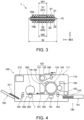
- FIG. 3 is a schematic cross-sectional view of the heater 1 in FIG. 1 in the A-A line direction.
- the heater 1 includes, for example, a substrate 10, an insulating part 21 (corresponding to an example of a first insulating part), an insulating part 22 (corresponding to an example of a second insulating part), a heating element 31 (corresponding to an example of a first heating element), a heating element 32 (corresponding to an example of a second heating element), a wiring part 41, a wiring part 42, a protection part 51 (corresponding to an example of a first protection film), and a protection part 52 (corresponding to an example of a second protection film).
- the insulating part 21, the heating element 31, the wiring part 41, and the protection part 51 are provided on one surface 10a of the substrate 10 in the Z direction.
- the insulating part 22, the heating element 32, the wiring part 42, and the protection part 52 are provided on another surface 10b of the substrate 10 in the Z direction.
- the substrate 10 has a plate shape and has the surface 10a (corresponding to an example of a first surface) and the surface 10b facing the surface 10a (corresponding to an example of a second surface).
- the substrate 10 has a shape extending in one direction (for example, the X direction).
- the planar shape of the substrate 10 is, for example, a long rectangular shape.
- the thickness of the substrate 10 is, for example, about 0.5 mm to 1.0 mm.
- the width dimension W (dimension in the lateral direction; dimension in the Y direction) of the substrate 10 is, for example, about 5 mm to 15 mm.
- the length L (dimension in the longitudinal direction; dimension in the X direction) of the substrate 10 may be appropriately changed depending on the size of the object to be heated (for example, paper) and the like.
- the substrate 10 is made of a material having heat resistance and high thermal conductivity. Generally, the substrate 10 is formed of ceramics such as aluminum oxide, but the heater 1 according to this embodiment is provided with the substrate 10 including metal.
- the metal may be, for example, stainless steel, an aluminum alloy, or the like.
- the insulating part 21 has an insulating property and is provided on the surface 10a of the substrate 10.
- the insulating part 21 may be provided, for example, to cover the surface 10a of the substrate 10.
- the insulating part 21 is provided to insulate between the substrate 10 including metal and the heating element 31 and the wiring part 41. Therefore, the insulating part 21 is provided between the substrate 10 and the heating element 31 and the wiring part 41.
- the insulating part 21 may be formed of, for example, an inorganic material such as ceramics or a glass material.
- the insulating part 21 may be formed by, for example, thermal spraying or firing.
- the heating element 31 converts the applied electric power into heat (Joule heat).
- the heating element 31 is provided on the insulating part 21 (the surface of the insulating part 21 opposite to the substrate 10 side).
- the heating element 31 extends, for example, along the longitudinal direction (X direction) of the substrate 10.
- the heating element 31 may be formed by using, for example, ruthenium oxide (RuO 2 ), a silver-palladium (Ag-Pd) alloy, or the like.
- the heating element 31 may be formed by, for example, applying a paste-like material on the insulating part 21 by using a screen printing method or the like and curing the paste-like material by using a firing method or the like.
- the wiring part 41 is provided, for example, on the surface of the insulating part 21 where the heating element 31 is provided.
- the wiring part 41 has, for example, a terminal 41a and a wiring 41b.
- a pair of terminals 41a may be provided.
- Each of the pair of terminals 41a may be provided, for example, near the ends on both sides of the substrate 10 in the X direction.
- the pair of terminals 41a are electrically connected to a power supply, a control circuit, or the like via, for example, a connector and wiring.
- a pair of wirings 41b may be provided.
- Each of the pair of wirings 41b electrically connects the terminal 41a and the heating element 31.
- One end of the wiring 41b is electrically connected to the terminal 41a.
- the other end of the wiring 41b is electrically connected to the heating element 31.
- the terminal 41a and the wiring 41b are formed by using a material including, for example, silver or copper.
- the terminal 41a and the wiring 41b may be formed by applying a paste-like material on the insulating part 21 by using a screen printing method or the like and curing the paste-like material by using a firing method or the like.
- the protection part 51 is provided on, for example, the insulating part 21 and extends along the longitudinal direction (X direction) of the substrate 10.
- the protection part 51 covers, for example, the heating element 31 and the wiring 41b. In this case, the terminal 41a is exposed from the protection part 51.
- the protection part 51 has, for example, a function of insulating the heating element 31 and the wiring 41b, a function of transmitting the heat generated in the heating element 31 to the outside, and a function of protecting the heating element 31 and the wiring 41b from external force, corrosive gas, and the like.
- the protection part 51 is made of a material having heat resistance and an insulating property, and having high chemical stability and thermal conductivity.
- the protection part 51 is formed of, for example, an inorganic material such as ceramics or a glass material. In this case, the protection part 51 may also be formed by using a glass material to which a filler including a material having high thermal conductivity such as aluminum oxide is added.
- the thermal conductivity of the glass material to which the filler is added may be, for example, 2 [W / (m ⁇ K)] or more.
- the protection part 51 is formed by, for example, applying a paste-like material on the insulating part 21, the heating element 31, and the wiring 41b by using a screen printing method or the like and curing the paste-like material by using a firing method or the like.
- the insulating part 22 has an insulating property and is provided on the surface 10b of the substrate 10.
- the insulating part 22 may be provided, for example, to cover the surface 10b of the substrate 10.
- the insulating part 22 is provided to insulate between the substrate 10 including metal and the heating element 32 and the wiring part 42. Therefore, the insulating part 22 is provided between the substrate 10 and the heating element 32 and the wiring part 42.
- the forming range, thickness, material, and forming method of the insulating part 22 may be, for example, the same as the forming range, thickness, material, and forming method of the insulating part 21 described above.
- the heating element 32 converts the applied electric power into heat (Joule heat).
- the heating element 32 is provided on the insulating part 22 (the surface of the insulating part 22 opposite to the substrate 10 side).
- the heating element 32 extends, for example, along the longitudinal direction (X direction) of the substrate 10.
- the heating element 32 may be formed by using, for example, ruthenium oxide (RuO2), a silver-palladium (Ag-Pd) alloy, or the like.
- the heating element 32 may be formed by, for example, applying a paste-like material on the insulating part 22 by using a screen printing method or the like and curing the paste-like material by using a firing method or the like.
- the wiring part 42 is provided, for example, on the surface of the insulating part 22 where the heating element 32 is provided.
- the wiring part 42 has, for example, a terminal 42a and a wiring 42b.
- a pair of terminals 42a may be provided.
- Each of the pair of terminals 42a may be provided, for example, near the ends on both sides of the substrate 10 in the X direction.
- the pair of terminals 42a are electrically connected to a power supply, a control circuit, or the like via, for example, a connector and wiring.
- a pair of wirings 42b may be provided.
- Each of the pair of wirings 42b electrically connects the terminal 42a and the heating element 32.
- One end of the wiring 42b is electrically connected to the terminal 42a.
- the other end of the wiring 42b is electrically connected to the heating element 32.
- the material and forming method of the terminal 42a and the wiring 42b may be the same as the material and forming method of the terminal 41a and the wiring 41b described above.
- the protection part 52 is provided on, for example, the insulating part 22 and extends along the longitudinal direction (X direction) of the substrate 10.
- the protection part 52 covers, for example, the heating element 32 and the wiring 42b. In this case, the terminal 42a is exposed from the protection part 52.
- the function, material, and forming method of the protection part 52 may be the same as the function, material, and forming method of the protection part 51 described above.
- the heater 1 may be further provided with a detection part for detecting the temperature of the heating element 31 and a detection part for detecting the temperature of the heating element 32.
- the detection part may be, for example, a thermistor or the like.
- the detection part may be provided on at least one of the side of the substrate 10 where the heating element 31 is provided and the side of the substrate 10 where the heating element 32 is provided. In this case, the protection parts 51 and 52 may cover the detection part.
- heating elements having different lengths may be arranged side by side in the Y direction on one surface of the substrate. By doing so, it is possible to select and use heating elements having different lengths according to the size of the object to be heated.
- the dimension (width dimension) of the substrate in the Y direction becomes large, and it becomes difficult to reduce the size of the heater.
- the temperature difference in the longitudinal direction of the long substrate becomes large.
- the substrate made of ceramics is used, if the temperature difference in the longitudinal direction of the long substrate becomes large, the substrate may be cracked due to thermal stress.
- the heater 1 includes the heating element 31 provided on the surface 10a of the substrate 10 and the heating element 32 provided on the surface 10b of the substrate 10. Further, as shown in FIGs. 1 and 2 , the length L2 of the heating element 32 in the X direction is different from the length L1 of the heating element 31 in the X direction. For example, the length L2 may be shorter than the length L1.
- the heating element 31 may be used for heating the A3 size paper, and the heating element 32 may be used for heating the B5 size paper.
- the length L1 may be about 322 mm.
- the heating element 32 is used for heating the B5 size paper, the length L2 may be about 184 mm.
- the center of the heating element 32 is at the same position as the center of the heating element 31 in the X direction.
- width dimension W2, thickness, and material of the heating element 32 may be the same as the width dimension W1, thickness, and material of the heating element 31, or any of them may be different.
- one heating element 31 may be provided.
- one heating element 32 may be provided.
- the number of the heating element 31 and the heating element 32 may be appropriately changed depending on the amount of heat applied to the object to be heated and the like.
- the multiple heating elements 31 are provided side by side in the Y direction.
- the multiple heating elements 32 are provided side by side in the Y direction. Therefore, the width dimension W of the substrate 10 becomes large, and it may be difficult to reduce the size of the heater 1.
- the number of heating elements 31 by changing the resistance value of the heating element 31 according to the required amount of heat generation.
- the number of heating elements 31 may be reduced by changing the material, width dimension W1, and thickness of the heating element 31.
- the number of heating elements 32 may be reduced by changing the resistance value of the heating element 32 according to the required amount of heat generation.
- the number of heating elements 32 may be reduced by changing the material, width dimension W2, and thickness of the heating element 32.
- the length of the heating element 31 and the length of the heating element 32 are different, switching between the heating element 31 and the heating element 32 changes the range in which the substrate 10 is heated. For example, when the heating element 31 is switched to the heating element 32, the range in which the substrate 10 is heated becomes smaller in the X direction. For example, when the heating element 32 is switched to the heating element 31, the range in which the substrate 10 is heated becomes larger in the X direction. When the range in which the substrate 10 is heated changes, it is conceivable that the substrate 10 may be deformed or damaged due to thermal stress. However, the surface 10a of the substrate 10 is provided with the insulating part 21, the wiring part 41, and the protection part 51.
- the surface 10b of the substrate 10 is provided with the insulating part 22, the wiring part 42, and the protection part 52. Therefore, for example, the thermal stress generated on the side of the surface 10a of the substrate 10 may be offset by the thermal stress generated on the side of the surface 10b of the substrate 10. As a result, it is possible to prevent the substrate 10 from being deformed or damaged.
- the substrate 10 is made of metal. Therefore, the rigidity and toughness of the substrate 10 may be increased. If the rigidity and toughness of the substrate 10 may be increased, it is possible to prevent the substrate 10 from being deformed or damaged even if thermal stress is generated by switching between the heating element 31 and the heating element 32.
- the heating range may be switched according to the size of the object to be heated, and the size may be reduced and the substrate 10 may be suppressed from being damaged.
- the image forming device 100 is a copying machine.
- the image forming device 100 is not limited to the copying machine, and may be any one provided with a heater for fixing the toner.
- the image forming device 100 may be a printer or the like. Further, it may be a rewritable card reader / writer or the like.
- FIG. 4 is a schematic view for illustrating the image forming device 100 according to this embodiment.
- FIG. 5 is a schematic view for illustrating a fixing part 200.
- the image forming device 100 includes, for example, a frame 110, an illumination part 120, an imaging element 130, a photosensitive drum 140, a charging part 150, a discharge part 151, a developing part 160, a cleaner 170, a housing part 180, a transport part 190, the fixing part 200, and a controller 210.
- the frame 110 has a box shape, and the frame 110 houses therein the illumination part 120, the imaging element 130, the photosensitive drum 140, the charging part 150, the developing part 160, the cleaner 170, a part of the housing part 180, the transport part 190, the fixing part 200, and the controller 210.
- a window 111 made of a translucent material such as glass may be provided on the upper surface of the frame 110.
- An original 500 to be copied is placed on the window 111. Further, a moving part for moving the position of the original 500 may be provided.
- the illumination part 120 is provided in the vicinity of the window 111.
- the illumination part 120 has, for example, a light source 121 such as a lamp and a reflector 122.
- the imaging element 130 is provided in the vicinity of the window 111.
- the photosensitive drum 140 is provided below the illumination part 120 and the imaging element 130.
- the photosensitive drum 140 is rotatably provided.
- a zinc oxide photosensitive layer or an organic semiconductor photosensitive layer is provided on the surface of the photosensitive drum 140.
- the charging part 150, the discharging part 151, the developing part 160, and the cleaner 170 are provided around the photosensitive drum 140.
- the housing part 180 has, for example, a cassette 181 and a tray 182.
- the cassette 181 is detachably attached to one side of the frame 110.
- the tray 182 is provided on the side of the frame 110 opposite to the side to which the cassette 181 is attached.
- Paper 510 (for example, blank paper) before copying is stored in the cassette 181.
- Paper 511 on which a copy image 511a is fixed is stored in the tray 182.
- the transport part 190 is provided below the photosensitive drum 140.
- the transport part 190 transports the paper 510 between the cassette 181 and the tray 182.
- the transport part 190 has, for example, a guide 191 that supports the paper 510 to be transported, and transport rollers 192 to 194 that transport the paper 510. Further, the transport part 190 may be provided with a motor for rotating the transport rollers 192 to 194.
- the fixing part 200 is provided on the downstream side (tray 182 side) of the photosensitive drum 140.
- the fixing part 200 has, for example, the heater 1, a stay 201, a film belt 202, and a pressure roller 203.
- the heater 1 is attached to the transport line side of the paper 510 of the stay 201.
- the heater 1 may be embedded in the stay 201.
- the side of the heater 1 provided with the protection part 51 may be exposed from the stay 201.
- the film belt 202 covers the stay 201 provided with the heater 1.
- the film belt 202 may be formed of, for example, a heat-resistant resin such as polyimide.
- the pressure roller 203 is provided to face the stay 201.
- the pressure roller 203 has, for example, a core metal 203a, a drive shaft 203b, and an elastic part 203c.
- the drive shaft 203b protrudes from the end of the core metal 203a and is connected to a drive device such as a motor.
- the elastic part 203c is provided on the outer surface of the core metal 203a.
- the elastic part 203c is formed of an elastic material having heat resistance.
- the elastic part 203c may be formed of, for example, a silicone resin or the like.
- the controller 210 is provided inside the frame 110.
- the controller 210 has, for example, a calculation part such as a central processing unit (CPU) and a storage part in which a control program is stored.
- the calculation part controls the operation of each element provided in the image forming device 100 based on the control program stored in the storage part.
- the controller 210 may also include an operation part for a user to input copying conditions and the like, a display part for displaying an operating state or an abnormality display, and the like.
Landscapes
- Physics & Mathematics (AREA)
- General Physics & Mathematics (AREA)
- Fixing For Electrophotography (AREA)
- Resistance Heating (AREA)
- Control Of Resistance Heating (AREA)
Abstract
Description
- Embodiments of the disclosure relate to a heater and an image forming device.
- An image forming device such as a copying machine or a printer is provided with a heater for fixing toner. Further, a heater is also provided in a print erasing device or the like provided in a rewritable card reader/writer or the like. Generally, such a heater has a long substrate, a heating element provided on one surface of the substrate and extending in the longitudinal direction of the substrate, and a protection part for covering the heating element.
- In recent years, it has been required to heat objects of different sizes with one heater, that is, to be versatile with respect to the size of the objects to be heated. Therefore, a heater has been proposed in which multiple heating elements are provided on one surface of a long substrate and the heating range is switched according to the size of the object to be heated.
- However, in such a heater, multiple heating elements are provided side by side in the lateral direction (width direction) of the long substrate. Therefore, it is difficult to reduce the size of the heater because the dimension of the substrate in the lateral direction becomes large.
- Further, in such a heater, a substrate made of ceramics is used. Therefore, when the heating range is switched according to the size of the object to be heated, the temperature difference in the longitudinal direction of the long substrate may become large, and the substrate may be cracked due to the generated thermal stress.
- Therefore, it has been desired to develop a technique capable of switching the heating range according to the size of the object to be heated and reducing the size and suppressing the damage of the substrate.
- [Patent Literature 1]
Japanese Patent Application Laid-Open No. 2009-244867 - The disclosure provides a heater and an image forming device capable of switching the heating range according to the size of the object to be heated, and capable of reducing the size and suppressing damage to the substrate.
- A heater according to an embodiment includes: a substrate including metal and having a shape extending in one direction; a first insulating part provided on a first surface of the substrate and having an insulating property; a first heating element provided on the first insulating part and extending along a longitudinal direction of the substrate; a first protection part provided on the first insulating part, extending along the longitudinal direction of the substrate and covering the first heating element; a second insulating part provided on a second surface of the substrate facing the first surface and having an insulating property; a second heating element provided on the second insulating part and extending along the longitudinal direction of the substrate; and a second protection part provided on the second insulating part, extending along the longitudinal direction of the substrate and covering the second heating element. A length of the second heating element is different from a length of the first heating element in the longitudinal direction of the substrate.
- According to an embodiment of the disclosure, it is possible to provide a heater and an image forming device capable of switching the heating range according to the size of the object to be heated, and capable of reducing the size and suppressing damage to the substrate.
-
-
FIG. 1 is a schematic view of a heater according to the embodiment as viewed from one side in the Z direction. -
FIG. 2 is a schematic view of the heater as viewed from the other side in the Z direction. -
FIG. 3 is a schematic cross-sectional view of the heater inFIG. 1 in the A-A line direction. -
FIG. 4 is a schematic view for illustrating an image forming device according to the embodiment. -
FIG. 5 is a schematic view for illustrating a fixing part. - Hereinafter, embodiments will be described with reference to the drawings. In each drawing, similar components are designated by the same reference numerals, and detailed description thereof will be omitted as appropriate. Further, the arrows X, Y, and Z in each drawing represent three directions orthogonal to each other. For example, the longitudinal direction of the substrate is the X direction; the lateral direction (width direction) of the substrate is the Y direction; and the direction perpendicular to the surface of the substrate is the Z direction.
-
FIG. 1 is a schematic view of aheater 1 according to this embodiment as viewed from one side in the Z direction. -
FIG. 2 is a schematic view of theheater 1 as viewed from the other side in the Z direction. -
FIG. 3 is a schematic cross-sectional view of theheater 1 inFIG. 1 in the A-A line direction. - As shown in
FIGs. 1 to 3 , theheater 1 includes, for example, asubstrate 10, an insulating part 21 (corresponding to an example of a first insulating part), an insulating part 22 (corresponding to an example of a second insulating part), a heating element 31 (corresponding to an example of a first heating element), a heating element 32 (corresponding to an example of a second heating element), awiring part 41, awiring part 42, a protection part 51 (corresponding to an example of a first protection film), and a protection part 52 (corresponding to an example of a second protection film). Theinsulating part 21, theheating element 31, thewiring part 41, and theprotection part 51 are provided on onesurface 10a of thesubstrate 10 in the Z direction. Theinsulating part 22, theheating element 32, thewiring part 42, and theprotection part 52 are provided on anothersurface 10b of thesubstrate 10 in the Z direction. - The
substrate 10 has a plate shape and has thesurface 10a (corresponding to an example of a first surface) and thesurface 10b facing thesurface 10a (corresponding to an example of a second surface). Thesubstrate 10 has a shape extending in one direction (for example, the X direction). The planar shape of thesubstrate 10 is, for example, a long rectangular shape. The thickness of thesubstrate 10 is, for example, about 0.5 mm to 1.0 mm. The width dimension W (dimension in the lateral direction; dimension in the Y direction) of thesubstrate 10 is, for example, about 5 mm to 15 mm. The length L (dimension in the longitudinal direction; dimension in the X direction) of thesubstrate 10 may be appropriately changed depending on the size of the object to be heated (for example, paper) and the like. - The
substrate 10 is made of a material having heat resistance and high thermal conductivity. Generally, thesubstrate 10 is formed of ceramics such as aluminum oxide, but theheater 1 according to this embodiment is provided with thesubstrate 10 including metal. The metal may be, for example, stainless steel, an aluminum alloy, or the like. - As shown in
FIGs. 1 and3 , theinsulating part 21 has an insulating property and is provided on thesurface 10a of thesubstrate 10. Theinsulating part 21 may be provided, for example, to cover thesurface 10a of thesubstrate 10. Theinsulating part 21 is provided to insulate between thesubstrate 10 including metal and theheating element 31 and thewiring part 41. Therefore, theinsulating part 21 is provided between thesubstrate 10 and theheating element 31 and thewiring part 41. Theinsulating part 21 may be formed of, for example, an inorganic material such as ceramics or a glass material. Theinsulating part 21 may be formed by, for example, thermal spraying or firing. - The
heating element 31 converts the applied electric power into heat (Joule heat). Theheating element 31 is provided on the insulating part 21 (the surface of theinsulating part 21 opposite to thesubstrate 10 side). - The
heating element 31 extends, for example, along the longitudinal direction (X direction) of thesubstrate 10. - The
heating element 31 may be formed by using, for example, ruthenium oxide (RuO2), a silver-palladium (Ag-Pd) alloy, or the like. Theheating element 31 may be formed by, for example, applying a paste-like material on theinsulating part 21 by using a screen printing method or the like and curing the paste-like material by using a firing method or the like. - The
wiring part 41 is provided, for example, on the surface of theinsulating part 21 where theheating element 31 is provided. Thewiring part 41 has, for example, aterminal 41a and awiring 41b. - For example, a pair of
terminals 41a may be provided. Each of the pair ofterminals 41a may be provided, for example, near the ends on both sides of thesubstrate 10 in the X direction. The pair ofterminals 41a are electrically connected to a power supply, a control circuit, or the like via, for example, a connector and wiring. - For example, a pair of
wirings 41b may be provided. Each of the pair ofwirings 41b electrically connects the terminal 41a and theheating element 31. One end of thewiring 41b is electrically connected to the terminal 41a. The other end of thewiring 41b is electrically connected to theheating element 31. - The terminal 41a and the
wiring 41b are formed by using a material including, for example, silver or copper. For example, the terminal 41a and thewiring 41b may be formed by applying a paste-like material on the insulatingpart 21 by using a screen printing method or the like and curing the paste-like material by using a firing method or the like. - The
protection part 51 is provided on, for example, the insulatingpart 21 and extends along the longitudinal direction (X direction) of thesubstrate 10. Theprotection part 51 covers, for example, theheating element 31 and thewiring 41b. In this case, theterminal 41a is exposed from theprotection part 51. - The
protection part 51 has, for example, a function of insulating theheating element 31 and thewiring 41b, a function of transmitting the heat generated in theheating element 31 to the outside, and a function of protecting theheating element 31 and thewiring 41b from external force, corrosive gas, and the like. Theprotection part 51 is made of a material having heat resistance and an insulating property, and having high chemical stability and thermal conductivity. Theprotection part 51 is formed of, for example, an inorganic material such as ceramics or a glass material. In this case, theprotection part 51 may also be formed by using a glass material to which a filler including a material having high thermal conductivity such as aluminum oxide is added. The thermal conductivity of the glass material to which the filler is added may be, for example, 2 [W / (m·K)] or more. - The
protection part 51 is formed by, for example, applying a paste-like material on the insulatingpart 21, theheating element 31, and thewiring 41b by using a screen printing method or the like and curing the paste-like material by using a firing method or the like. - As shown in
FIGs. 2 and3 , the insulatingpart 22 has an insulating property and is provided on thesurface 10b of thesubstrate 10. The insulatingpart 22 may be provided, for example, to cover thesurface 10b of thesubstrate 10. The insulatingpart 22 is provided to insulate between thesubstrate 10 including metal and theheating element 32 and thewiring part 42. Therefore, the insulatingpart 22 is provided between thesubstrate 10 and theheating element 32 and thewiring part 42. The forming range, thickness, material, and forming method of the insulatingpart 22 may be, for example, the same as the forming range, thickness, material, and forming method of the insulatingpart 21 described above. - The
heating element 32 converts the applied electric power into heat (Joule heat). Theheating element 32 is provided on the insulating part 22 (the surface of the insulatingpart 22 opposite to thesubstrate 10 side). - The
heating element 32 extends, for example, along the longitudinal direction (X direction) of thesubstrate 10. Theheating element 32 may be formed by using, for example, ruthenium oxide (RuO2), a silver-palladium (Ag-Pd) alloy, or the like. Theheating element 32 may be formed by, for example, applying a paste-like material on the insulatingpart 22 by using a screen printing method or the like and curing the paste-like material by using a firing method or the like. - The
wiring part 42 is provided, for example, on the surface of the insulatingpart 22 where theheating element 32 is provided. Thewiring part 42 has, for example, a terminal 42a and awiring 42b. - For example, a pair of
terminals 42a may be provided. Each of the pair ofterminals 42a may be provided, for example, near the ends on both sides of thesubstrate 10 in the X direction. The pair ofterminals 42a are electrically connected to a power supply, a control circuit, or the like via, for example, a connector and wiring. - For example, a pair of
wirings 42b may be provided. Each of the pair ofwirings 42b electrically connects the terminal 42a and theheating element 32. One end of thewiring 42b is electrically connected to the terminal 42a. The other end of thewiring 42b is electrically connected to theheating element 32. - The material and forming method of the terminal 42a and the
wiring 42b may be the same as the material and forming method of the terminal 41a and thewiring 41b described above. - The
protection part 52 is provided on, for example, the insulatingpart 22 and extends along the longitudinal direction (X direction) of thesubstrate 10. Theprotection part 52 covers, for example, theheating element 32 and thewiring 42b. In this case, theterminal 42a is exposed from theprotection part 52. - The function, material, and forming method of the
protection part 52 may be the same as the function, material, and forming method of theprotection part 51 described above. - Further, the
heater 1 may be further provided with a detection part for detecting the temperature of theheating element 31 and a detection part for detecting the temperature of theheating element 32. The detection part may be, for example, a thermistor or the like. The detection part may be provided on at least one of the side of thesubstrate 10 where theheating element 31 is provided and the side of thesubstrate 10 where theheating element 32 is provided. In this case, theprotection parts - Here, in recent years, it has been required to heat objects of different sizes with one heater, that is, to be versatile with respect to the size of the objects to be heated. In this case, heating elements having different lengths may be arranged side by side in the Y direction on one surface of the substrate. By doing so, it is possible to select and use heating elements having different lengths according to the size of the object to be heated. However, in this case, the dimension (width dimension) of the substrate in the Y direction becomes large, and it becomes difficult to reduce the size of the heater. Further, when the heating range is switched according to the size of the object to be heated, the temperature difference in the longitudinal direction of the long substrate becomes large. Generally, since a substrate made of ceramics is used, if the temperature difference in the longitudinal direction of the long substrate becomes large, the substrate may be cracked due to thermal stress.
- Therefore, the
heater 1 according to this embodiment includes theheating element 31 provided on thesurface 10a of thesubstrate 10 and theheating element 32 provided on thesurface 10b of thesubstrate 10. Further, as shown inFIGs. 1 and2 , the length L2 of theheating element 32 in the X direction is different from the length L1 of theheating element 31 in the X direction. For example, the length L2 may be shorter than the length L1. - For example, when the objects to be heated are A3 size paper and B5 size paper, the
heating element 31 may be used for heating the A3 size paper, and theheating element 32 may be used for heating the B5 size paper. When theheating element 31 is used for heating the A3 size paper, the length L1 may be about 322 mm. When theheating element 32 is used for heating the B5 size paper, the length L2 may be about 184 mm. - Further, it is preferable that the center of the
heating element 32 is at the same position as the center of theheating element 31 in the X direction. By doing so, when theheater 1 is attached to theimage forming device 100, it becomes easy to make the center of theheating element 31 and theheating element 32 overlap with the center of the transport path of the object to be heated. Therefore, even when the dimensions of the object to be heated change in the direction orthogonal to the transport direction, it becomes easy to heat the object to be heated substantially uniformly. - Further, the width dimension W2, thickness, and material of the
heating element 32 may be the same as the width dimension W1, thickness, and material of theheating element 31, or any of them may be different. - Although in
FIGs. 1 to 3 , the case where oneheating element 31 is provided is shown, one ormore heating elements 31 may be provided. Further, though inFIGs. 1 to 3 , the case where oneheating element 32 is provided is shown, one ormore heating elements 32 may be provided. The number of theheating element 31 and theheating element 32 may be appropriately changed depending on the amount of heat applied to the object to be heated and the like. However, whenmultiple heating elements 31 are provided, themultiple heating elements 31 are provided side by side in the Y direction. Whenmultiple heating elements 32 are provided, themultiple heating elements 32 are provided side by side in the Y direction. Therefore, the width dimension W of thesubstrate 10 becomes large, and it may be difficult to reduce the size of theheater 1. - Therefore, it is preferable to reduce the number of
heating elements 31 by changing the resistance value of theheating element 31 according to the required amount of heat generation. For example, the number ofheating elements 31 may be reduced by changing the material, width dimension W1, and thickness of theheating element 31. - Further, it is preferable to reduce the number of
heating elements 32 by changing the resistance value of theheating element 32 according to the required amount of heat generation. For example, the number ofheating elements 32 may be reduced by changing the material, width dimension W2, and thickness of theheating element 32. - Further, since the length of the
heating element 31 and the length of theheating element 32 are different, switching between theheating element 31 and theheating element 32 changes the range in which thesubstrate 10 is heated. For example, when theheating element 31 is switched to theheating element 32, the range in which thesubstrate 10 is heated becomes smaller in the X direction. For example, when theheating element 32 is switched to theheating element 31, the range in which thesubstrate 10 is heated becomes larger in the X direction. When the range in which thesubstrate 10 is heated changes, it is conceivable that thesubstrate 10 may be deformed or damaged due to thermal stress. However, thesurface 10a of thesubstrate 10 is provided with the insulatingpart 21, thewiring part 41, and theprotection part 51. Thesurface 10b of thesubstrate 10 is provided with the insulatingpart 22, thewiring part 42, and theprotection part 52. Therefore, for example, the thermal stress generated on the side of thesurface 10a of thesubstrate 10 may be offset by the thermal stress generated on the side of thesurface 10b of thesubstrate 10. As a result, it is possible to prevent thesubstrate 10 from being deformed or damaged. - Further, as described above, the
substrate 10 is made of metal. Therefore, the rigidity and toughness of thesubstrate 10 may be increased. If the rigidity and toughness of thesubstrate 10 may be increased, it is possible to prevent thesubstrate 10 from being deformed or damaged even if thermal stress is generated by switching between theheating element 31 and theheating element 32. - As described above, if the
heater 1 according to this embodiment is used, the heating range may be switched according to the size of the object to be heated, and the size may be reduced and thesubstrate 10 may be suppressed from being damaged. - Next, an example of an
image forming device 100 according to this embodiment will be described. - In the following, as an example, a case where the
image forming device 100 is a copying machine will be described. However, theimage forming device 100 is not limited to the copying machine, and may be any one provided with a heater for fixing the toner. For example, theimage forming device 100 may be a printer or the like. Further, it may be a rewritable card reader / writer or the like. -
FIG. 4 is a schematic view for illustrating theimage forming device 100 according to this embodiment. -
FIG. 5 is a schematic view for illustrating a fixingpart 200. - As shown in
FIG. 4 , theimage forming device 100 includes, for example, aframe 110, anillumination part 120, animaging element 130, aphotosensitive drum 140, a chargingpart 150, adischarge part 151, a developingpart 160, a cleaner 170, ahousing part 180, atransport part 190, the fixingpart 200, and acontroller 210. - The
frame 110 has a box shape, and theframe 110 houses therein theillumination part 120, theimaging element 130, thephotosensitive drum 140, the chargingpart 150, the developingpart 160, the cleaner 170, a part of thehousing part 180, thetransport part 190, the fixingpart 200, and thecontroller 210. - A
window 111 made of a translucent material such as glass may be provided on the upper surface of theframe 110. An original 500 to be copied is placed on thewindow 111. Further, a moving part for moving the position of the original 500 may be provided. - The
illumination part 120 is provided in the vicinity of thewindow 111. Theillumination part 120 has, for example, alight source 121 such as a lamp and areflector 122. - The
imaging element 130 is provided in the vicinity of thewindow 111. - The
photosensitive drum 140 is provided below theillumination part 120 and theimaging element 130. Thephotosensitive drum 140 is rotatably provided. For example, a zinc oxide photosensitive layer or an organic semiconductor photosensitive layer is provided on the surface of thephotosensitive drum 140. - The charging
part 150, the dischargingpart 151, the developingpart 160, and the cleaner 170 are provided around thephotosensitive drum 140. - The
housing part 180 has, for example, acassette 181 and atray 182. Thecassette 181 is detachably attached to one side of theframe 110. Thetray 182 is provided on the side of theframe 110 opposite to the side to which thecassette 181 is attached. Paper 510 (for example, blank paper) before copying is stored in thecassette 181.Paper 511 on which acopy image 511a is fixed is stored in thetray 182. - The
transport part 190 is provided below thephotosensitive drum 140. Thetransport part 190 transports thepaper 510 between thecassette 181 and thetray 182. Thetransport part 190 has, for example, aguide 191 that supports thepaper 510 to be transported, andtransport rollers 192 to 194 that transport thepaper 510. Further, thetransport part 190 may be provided with a motor for rotating thetransport rollers 192 to 194. - The fixing
part 200 is provided on the downstream side (tray 182 side) of thephotosensitive drum 140. - As shown in
FIG. 5 , the fixingpart 200 has, for example, theheater 1, astay 201, afilm belt 202, and apressure roller 203. - The
heater 1 is attached to the transport line side of thepaper 510 of thestay 201. Theheater 1 may be embedded in thestay 201. For example, the side of theheater 1 provided with theprotection part 51 may be exposed from thestay 201. - The
film belt 202 covers thestay 201 provided with theheater 1. Thefilm belt 202 may be formed of, for example, a heat-resistant resin such as polyimide. - The
pressure roller 203 is provided to face thestay 201. Thepressure roller 203 has, for example, acore metal 203a, adrive shaft 203b, and anelastic part 203c. Thedrive shaft 203b protrudes from the end of thecore metal 203a and is connected to a drive device such as a motor. Theelastic part 203c is provided on the outer surface of thecore metal 203a. Theelastic part 203c is formed of an elastic material having heat resistance. Theelastic part 203c may be formed of, for example, a silicone resin or the like. - The
controller 210 is provided inside theframe 110. Thecontroller 210 has, for example, a calculation part such as a central processing unit (CPU) and a storage part in which a control program is stored. The calculation part controls the operation of each element provided in theimage forming device 100 based on the control program stored in the storage part. Further, thecontroller 210 may also include an operation part for a user to input copying conditions and the like, a display part for displaying an operating state or an abnormality display, and the like. - Since known techniques may be applied to the control of each element provided in the
image forming device 100, detailed description thereof will be omitted. - 1: heater; 10: substrate; 10a: surface; 10b: surface; 21: insulating part; 22: insulating part; 31: heating element; 32: heating element; 41: wiring part; 42: wiring part; 51: protection part; 52: protection part; 100: image forming device; 200: fixing part
Claims (3)
- A heater (1) comprising:a substrate (10) comprising metal and having a shape extending in one direction;a first insulating part (21) provided on a first surface (10a) of the substrate and having an insulating property;a first heating element (31) provided on the first insulating part and extending along a longitudinal direction of the substrate;a first protection part (51) provided on the first insulating part, extending along the longitudinal direction of the substrate and covering the first heating element;a second insulating part (22) provided on a second surface (10b) of the substrate facing the first surface and having an insulating property;a second heating element (32) provided on the second insulating part and extending along the longitudinal direction of the substrate; anda second protection part (52) provided on the second insulating part, extending along the longitudinal direction of the substrate and covering the second heating element;wherein a length of the second heating element is different from a length of the first heating element in the longitudinal direction of the substrate.
- The heater according to claim 1, wherein a center of the second heating element is located at a same position as a center of the first heating element in the longitudinal direction of the substrate.
- An image forming device (100) comprising the heater according to claim 1 or 2.
Applications Claiming Priority (1)
| Application Number | Priority Date | Filing Date | Title |
|---|---|---|---|
| JP2021200267A JP7751791B2 (en) | 2021-12-09 | 2021-12-09 | Heater and image forming apparatus |
Publications (1)
| Publication Number | Publication Date |
|---|---|
| EP4194954A1 true EP4194954A1 (en) | 2023-06-14 |
Family
ID=82899095
Family Applications (1)
| Application Number | Title | Priority Date | Filing Date |
|---|---|---|---|
| EP22190103.6A Pending EP4194954A1 (en) | 2021-12-09 | 2022-08-12 | Heater and image forming device |
Country Status (5)
| Country | Link |
|---|---|
| US (1) | US11947292B2 (en) |
| EP (1) | EP4194954A1 (en) |
| JP (1) | JP7751791B2 (en) |
| KR (1) | KR20230087360A (en) |
| CN (1) | CN116256955A (en) |
Families Citing this family (1)
| Publication number | Priority date | Publication date | Assignee | Title |
|---|---|---|---|---|
| US11709448B2 (en) * | 2020-06-30 | 2023-07-25 | Canon Kabushiki Kaisha | Fixing unit and image forming apparatus |
Citations (7)
| Publication number | Priority date | Publication date | Assignee | Title |
|---|---|---|---|---|
| JP2003337484A (en) * | 2002-05-21 | 2003-11-28 | Canon Inc | Heating device and image forming device |
| JP2009244867A (en) | 2008-03-14 | 2009-10-22 | Canon Inc | Image heating apparatus and heater used for the image heating apparatus |
| JP2013073206A (en) * | 2011-09-29 | 2013-04-22 | Canon Inc | Image heating device |
| EP2975466A2 (en) * | 2014-07-18 | 2016-01-20 | Canon Kabushiki Kaisha | Fixing apparatus |
| US20160238974A1 (en) * | 2015-02-16 | 2016-08-18 | Canon Kabushiki Kaisha | Fixing device |
| US20200033771A1 (en) * | 2018-07-25 | 2020-01-30 | Ricoh Company, Ltd. | Heating device, fixing device, and image forming apparatus |
| JP2020149832A (en) * | 2019-03-13 | 2020-09-17 | 東芝ライテック株式会社 | Heater and image forming device |
Family Cites Families (2)
| Publication number | Priority date | Publication date | Assignee | Title |
|---|---|---|---|---|
| JP2021006878A (en) * | 2019-06-28 | 2021-01-21 | キヤノン株式会社 | Fixing belt unit |
| JP7558724B2 (en) * | 2020-09-01 | 2024-10-01 | 東芝テック株式会社 | HEATER UNIT, FIXING DEVICE AND IMAGE FORMING APPARATUS |
-
2021
- 2021-12-09 JP JP2021200267A patent/JP7751791B2/en active Active
-
2022
- 2022-08-11 CN CN202210960166.2A patent/CN116256955A/en active Pending
- 2022-08-12 EP EP22190103.6A patent/EP4194954A1/en active Pending
- 2022-08-12 US US17/886,467 patent/US11947292B2/en active Active
- 2022-08-17 KR KR1020220102614A patent/KR20230087360A/en active Pending
Patent Citations (7)
| Publication number | Priority date | Publication date | Assignee | Title |
|---|---|---|---|---|
| JP2003337484A (en) * | 2002-05-21 | 2003-11-28 | Canon Inc | Heating device and image forming device |
| JP2009244867A (en) | 2008-03-14 | 2009-10-22 | Canon Inc | Image heating apparatus and heater used for the image heating apparatus |
| JP2013073206A (en) * | 2011-09-29 | 2013-04-22 | Canon Inc | Image heating device |
| EP2975466A2 (en) * | 2014-07-18 | 2016-01-20 | Canon Kabushiki Kaisha | Fixing apparatus |
| US20160238974A1 (en) * | 2015-02-16 | 2016-08-18 | Canon Kabushiki Kaisha | Fixing device |
| US20200033771A1 (en) * | 2018-07-25 | 2020-01-30 | Ricoh Company, Ltd. | Heating device, fixing device, and image forming apparatus |
| JP2020149832A (en) * | 2019-03-13 | 2020-09-17 | 東芝ライテック株式会社 | Heater and image forming device |
Also Published As
| Publication number | Publication date |
|---|---|
| KR20230087360A (en) | 2023-06-16 |
| JP7751791B2 (en) | 2025-10-09 |
| US11947292B2 (en) | 2024-04-02 |
| CN116256955A (en) | 2023-06-13 |
| US20230185221A1 (en) | 2023-06-15 |
| JP2023085939A (en) | 2023-06-21 |
Similar Documents
| Publication | Publication Date | Title |
|---|---|---|
| JP7167780B2 (en) | Heaters and image forming devices | |
| US11947292B2 (en) | Heater and image forming device | |
| KR102768217B1 (en) | Heater and image forming apparatus | |
| JP2023072316A (en) | Heaters and image forming devices | |
| EP4336272B1 (en) | Heater and image forming apparatus | |
| EP4075202B1 (en) | Heater, and image forming apparatus | |
| JP7861306B2 (en) | Heater and image forming apparatus | |
| US20250102978A1 (en) | Heater and image forming device | |
| JP7738828B2 (en) | Heater and image forming apparatus | |
| JP7691659B2 (en) | HEATER AND IMAGE FORMING APPARATUS | |
| JP2024077755A (en) | HEATER AND IMAGE FORMING APPARATUS | |
| JP7534709B2 (en) | HEATER AND IMAGE FORMING APPARATUS | |
| JP2025019627A (en) | HEATER AND IMAGE FORMING APPARATUS | |
| JP2024037510A (en) | Heater and image forming device | |
| JP2020187319A (en) | Heater and image forming device | |
| JP2025019626A (en) | HEATER AND IMAGE FORMING APPARATUS | |
| JP2024114290A (en) | HEATER AND IMAGE FORMING APPARATUS | |
| JP2025091956A (en) | HEATER AND IMAGE FORMING APPARATUS | |
| JP2024016481A (en) | Heater and image forming device | |
| JP2024113384A (en) | HEATER AND IMAGE FORMING APPARATUS | |
| EP4030240A1 (en) | Heater and image forming apparatus | |
| JP2024005361A (en) | Heater, and image forming apparatus | |
| JP2023089444A (en) | Heaters and image forming devices | |
| JP2024002032A (en) | Heater and image forming device | |
| JP2024008052A (en) | Heater and image forming device |
Legal Events
| Date | Code | Title | Description |
|---|---|---|---|
| PUAI | Public reference made under article 153(3) epc to a published international application that has entered the european phase |
Free format text: ORIGINAL CODE: 0009012 |
|
| STAA | Information on the status of an ep patent application or granted ep patent |
Free format text: STATUS: THE APPLICATION HAS BEEN PUBLISHED |
|
| AK | Designated contracting states |
Kind code of ref document: A1 Designated state(s): AL AT BE BG CH CY CZ DE DK EE ES FI FR GB GR HR HU IE IS IT LI LT LU LV MC MK MT NL NO PL PT RO RS SE SI SK SM TR |
|
| STAA | Information on the status of an ep patent application or granted ep patent |
Free format text: STATUS: REQUEST FOR EXAMINATION WAS MADE |
|
| 17P | Request for examination filed |
Effective date: 20231004 |
|
| RBV | Designated contracting states (corrected) |
Designated state(s): AL AT BE BG CH CY CZ DE DK EE ES FI FR GB GR HR HU IE IS IT LI LT LU LV MC MK MT NL NO PL PT RO RS SE SI SK SM TR |
|
| STAA | Information on the status of an ep patent application or granted ep patent |
Free format text: STATUS: EXAMINATION IS IN PROGRESS |
|
| 17Q | First examination report despatched |
Effective date: 20250917 |