EP4194786B1 - Additive airfoil heat exchanger - Google Patents
Additive airfoil heat exchanger Download PDFInfo
- Publication number
- EP4194786B1 EP4194786B1 EP22212890.2A EP22212890A EP4194786B1 EP 4194786 B1 EP4194786 B1 EP 4194786B1 EP 22212890 A EP22212890 A EP 22212890A EP 4194786 B1 EP4194786 B1 EP 4194786B1
- Authority
- EP
- European Patent Office
- Prior art keywords
- heat exchanger
- airfoils
- fin
- airfoil
- passage
- Prior art date
- Legal status (The legal status is an assumption and is not a legal conclusion. Google has not performed a legal analysis and makes no representation as to the accuracy of the status listed.)
- Active
Links
Images



Classifications
-
- F—MECHANICAL ENGINEERING; LIGHTING; HEATING; WEAPONS; BLASTING
- F28—HEAT EXCHANGE IN GENERAL
- F28D—HEAT-EXCHANGE APPARATUS, NOT PROVIDED FOR IN ANOTHER SUBCLASS, IN WHICH THE HEAT-EXCHANGE MEDIA DO NOT COME INTO DIRECT CONTACT
- F28D1/00—Heat-exchange apparatus having stationary conduit assemblies for one heat-exchange medium only, the media being in contact with different sides of the conduit wall, in which the other heat-exchange medium is a large body of fluid, e.g. domestic or motor car radiators
- F28D1/02—Heat-exchange apparatus having stationary conduit assemblies for one heat-exchange medium only, the media being in contact with different sides of the conduit wall, in which the other heat-exchange medium is a large body of fluid, e.g. domestic or motor car radiators with heat-exchange conduits immersed in the body of fluid
- F28D1/04—Heat-exchange apparatus having stationary conduit assemblies for one heat-exchange medium only, the media being in contact with different sides of the conduit wall, in which the other heat-exchange medium is a large body of fluid, e.g. domestic or motor car radiators with heat-exchange conduits immersed in the body of fluid with tubular conduits
- F28D1/053—Heat-exchange apparatus having stationary conduit assemblies for one heat-exchange medium only, the media being in contact with different sides of the conduit wall, in which the other heat-exchange medium is a large body of fluid, e.g. domestic or motor car radiators with heat-exchange conduits immersed in the body of fluid with tubular conduits the conduits being straight
- F28D1/0535—Heat-exchange apparatus having stationary conduit assemblies for one heat-exchange medium only, the media being in contact with different sides of the conduit wall, in which the other heat-exchange medium is a large body of fluid, e.g. domestic or motor car radiators with heat-exchange conduits immersed in the body of fluid with tubular conduits the conduits being straight the conduits having a non-circular cross-section
- F28D1/05366—Assemblies of conduits connected to common headers, e.g. core type radiators
-
- F—MECHANICAL ENGINEERING; LIGHTING; HEATING; WEAPONS; BLASTING
- F28—HEAT EXCHANGE IN GENERAL
- F28D—HEAT-EXCHANGE APPARATUS, NOT PROVIDED FOR IN ANOTHER SUBCLASS, IN WHICH THE HEAT-EXCHANGE MEDIA DO NOT COME INTO DIRECT CONTACT
- F28D1/00—Heat-exchange apparatus having stationary conduit assemblies for one heat-exchange medium only, the media being in contact with different sides of the conduit wall, in which the other heat-exchange medium is a large body of fluid, e.g. domestic or motor car radiators
- F28D1/02—Heat-exchange apparatus having stationary conduit assemblies for one heat-exchange medium only, the media being in contact with different sides of the conduit wall, in which the other heat-exchange medium is a large body of fluid, e.g. domestic or motor car radiators with heat-exchange conduits immersed in the body of fluid
- F28D1/04—Heat-exchange apparatus having stationary conduit assemblies for one heat-exchange medium only, the media being in contact with different sides of the conduit wall, in which the other heat-exchange medium is a large body of fluid, e.g. domestic or motor car radiators with heat-exchange conduits immersed in the body of fluid with tubular conduits
- F28D1/053—Heat-exchange apparatus having stationary conduit assemblies for one heat-exchange medium only, the media being in contact with different sides of the conduit wall, in which the other heat-exchange medium is a large body of fluid, e.g. domestic or motor car radiators with heat-exchange conduits immersed in the body of fluid with tubular conduits the conduits being straight
- F28D1/0535—Heat-exchange apparatus having stationary conduit assemblies for one heat-exchange medium only, the media being in contact with different sides of the conduit wall, in which the other heat-exchange medium is a large body of fluid, e.g. domestic or motor car radiators with heat-exchange conduits immersed in the body of fluid with tubular conduits the conduits being straight the conduits having a non-circular cross-section
- F28D1/05366—Assemblies of conduits connected to common headers, e.g. core type radiators
- F28D1/05383—Assemblies of conduits connected to common headers, e.g. core type radiators with multiple rows of conduits or with multi-channel conduits
-
- F—MECHANICAL ENGINEERING; LIGHTING; HEATING; WEAPONS; BLASTING
- F28—HEAT EXCHANGE IN GENERAL
- F28F—DETAILS OF HEAT-EXCHANGE AND HEAT-TRANSFER APPARATUS, OF GENERAL APPLICATION
- F28F1/00—Tubular elements; Assemblies of tubular elements
- F28F1/02—Tubular elements of cross-section which is non-circular
- F28F1/022—Tubular elements of cross-section which is non-circular with multiple channels
-
- F—MECHANICAL ENGINEERING; LIGHTING; HEATING; WEAPONS; BLASTING
- F28—HEAT EXCHANGE IN GENERAL
- F28F—DETAILS OF HEAT-EXCHANGE AND HEAT-TRANSFER APPARATUS, OF GENERAL APPLICATION
- F28F1/00—Tubular elements; Assemblies of tubular elements
- F28F1/08—Tubular elements crimped or corrugated in longitudinal section
-
- F—MECHANICAL ENGINEERING; LIGHTING; HEATING; WEAPONS; BLASTING
- F28—HEAT EXCHANGE IN GENERAL
- F28F—DETAILS OF HEAT-EXCHANGE AND HEAT-TRANSFER APPARATUS, OF GENERAL APPLICATION
- F28F1/00—Tubular elements; Assemblies of tubular elements
- F28F1/10—Tubular elements and assemblies thereof with means for increasing heat-transfer area, e.g. with fins, with projections, with recesses
- F28F1/12—Tubular elements and assemblies thereof with means for increasing heat-transfer area, e.g. with fins, with projections, with recesses the means being only outside the tubular element
- F28F1/24—Tubular elements and assemblies thereof with means for increasing heat-transfer area, e.g. with fins, with projections, with recesses the means being only outside the tubular element and extending transversely
- F28F1/32—Tubular elements and assemblies thereof with means for increasing heat-transfer area, e.g. with fins, with projections, with recesses the means being only outside the tubular element and extending transversely the means having portions engaging further tubular elements
-
- F—MECHANICAL ENGINEERING; LIGHTING; HEATING; WEAPONS; BLASTING
- F28—HEAT EXCHANGE IN GENERAL
- F28F—DETAILS OF HEAT-EXCHANGE AND HEAT-TRANSFER APPARATUS, OF GENERAL APPLICATION
- F28F2250/00—Arrangements for modifying the flow of the heat exchange media, e.g. flow guiding means; Particular flow patterns
- F28F2250/02—Streamline-shaped elements
Definitions
- This disclosure relates to a heat exchanger, and in particular, to an additively manufactured heat exchanger.
- Heat exchangers are often used to transfer heat between two fluids.
- heat exchangers are used on aircraft to transfer heat between a relatively hot air source, e.g., bleed air from a gas turbine engine, and a relatively cool air source, e.g., ram air.
- US 20100006276 A1 discloses a heat exchanger according to the preamble of claim 1 and describes heat exchangers that include multichannel tube and fin configurations designed to promote the release of condensate.
- the multichannel tubes may have a curved, round, or airfoil shape, and may be used with plate or corrugated fins.
- US 20100263847 A1 describes a microchannel heat exchanger including at least one manifold for distributing fluid and a plurality of tubes extending from the at least one manifold.
- WO 2018083423 A1 describes a heat exchanger with mechanical assembly, comprising a plurality of heat exchange elements, and a plurality of tubes mechanically assembled to the heat exchange elements, the tubes respectively comprising an outer casing delimiting a channel for the flow of a first fluid.
- JPS5221447U describes a heat exchange between fluids having a temperature difference through a conduit, wherein the one fluid flows around the conduit and the flow direction is forcibly changed.
- the heat exchanger core includes a primary passage defined between a first fin and a second fin that extends through the heat exchanger core.
- the heat exchanger core also includes a plurality of airfoils that extend within the primary passages from the first fin to the second fin. At least one airfoil of the plurality of airfoils includes a secondary passage that extends through the heat exchanger core within the at least one airfoil transverse to the primary passage.
- FIG. 1 is a perspective view of heat exchanger 10.
- Heat exchanger 10 includes heat exchanger core 12 and headers 70.
- Heat exchanger core 12 includes first side 20, second side 22, third side 24, fourth side 26, fifth side 28, sixth side 30, a plurality of fins 39 that includes first fin 40 and second fin 42, and primary passages 44.
- Each of primary passages 44 includes primary inlet 46 and primary outlet 48.
- One of primary passages 44 extends between first fin 40 and second fin 42.
- Header 70 includes inlet 72, plenum 74, and plurality of outlets 76 (hereinafter referred to as "outlets 76").
- Heat exchanger 10 also includes first direction A, second direction B, and third direction C.
- Second side 22 is opposite of first side 20.
- Third side 24 extends from first side 20 to second side 22.
- Fourth side 26 is opposite third side 24 and extends from first side 20 to second side 22.
- Fifth side 28 extends from first side 20 to second side 22 and extends from third side 24 to fourth side 26.
- Sixth side 30 is opposite fifth side 28 and extends from first side 20 to second side 22 and extends from third side 24 to fourth side 26.
- First fin 40 extends from first side 20 to second side 22 in first direction A and extends from fifth side 28 to sixth side 30 in second direction B.
- Second fin 42 extends from first side 20 to second side 22 in first direction A and extends from fifth side 28 to sixth side 30 in second direction B.
- Second fin 42 is spaced apart from first fin 40 in third direction C.
- Primary passage 44 extends from first side 20 to second side 22 and from fifth side 28 and sixth side 30 between first fin 40 and second fin 42 from primary inlet 46 to primary outlet 48.
- Primary inlet 46 is on first side 20 and primary outlet 48 is on second side 22.
- first fin 40 and second fin 42 are corrugated.
- first fin 40 and second fin 42 helps to provide structural support to heat exchanger core 12 and enable heat exchanger core 12 to be additively manufactured without additional supports.
- first fin 40 and second fin 42 can have a sinusoidal, repeating chevron, or any other shape that enables first fin 40 and second fin 42 to be additively manufactured.
- Header 70 is on third side 24 of heat exchanger core 12.
- Plenum 74 is fluidically between inlet 72 and outlets 76.
- Outlets 76 of header 70 are fluidically connected to secondary passage 64 (first shown in FIG. 2 ).
- Header 70 can also be on fourth side 26 of heat exchanger core 12.
- header 70 includes inlets 72, plenum 74 and outlet 76.
- Inlet 72 are fluidically connected to secondary passage 64 opposite of header 70 on third side 24 of heat exchanger core 12.
- FIG. 2 is a cross-sectional view of the heat exchanger from FIG. 1 taken along line A-A.
- heat exchanger core 12 includes plurality of airfoils 50.
- Each airfoil 50 in the plurality of airfoils 50 includes leading edge 56, trailing edge 58, pressure side 60, suction side 62, and at least one secondary passage 64.
- Airfoils 50 are positioned within primary passage 44.
- Airfoils 50 include a base (not shown) on fourth side 26 and a tip (not shown) on third side 24.
- Each of airfoils 50 has a height extending from the base to the tip.
- Leading edge 56 extends from first fin 40 to second fin 42 along the height of each airfoil 50.
- Trailing edge 58 is opposite leading edge 56 and extends along the height of each airfoil 50.
- Each airfoil 50 has a chord length spanning from leading edge 56 to trailing edge 58.
- Pressure side 60 of each airfoil 50 extends between leading edge 56 and trailing edge 58 and extends along the height of each airfoil 50.
- Suction side 62 of each airfoil 50 is opposite of pressure side 60 and extends between leading edge 56 and trailing edge 58 and extends along the height of each airfoil 50.
- Each airfoil 50 has a thickness spanning from pressure side 60 to suction side 62.
- Each airfoil 50 is positioned so that leading edge 56 faces primary inlet 46 and trailing edge 58 faces primary outlet 48. As shown in FIG. 2 , suction side 62 of airfoils 50 can face sixth side 30 and pressure side 60 of airfoils 50 can face fifth side 28.
- Airfoils 50 are within each primary passage 44 to help guide the air that flows through primary passage 44 to limit the pressure drop through primary passage 44. Airfoils 50 also provide structural support throughout heat exchanger core 12 of heat exchanger 10 and provide a structure to house secondary passages 64. Moreover, the airfoil shape of airfoils 50 has a greater surface area within primary passage 44 than if secondary passages 64 were housed within simple tubes or pipes. The increased surface area of airfoils 50 provides more heat transfer surface between primary passage 44 and secondary passage 64. Therefore, the airfoil shape of airfoils 50 increases the heat transfer between the air flowing through primary passage 44 and the fluid flowing through secondary passage 64.
- Each of secondary passages 64 extend through heat exchanger core 12 within one of airfoils 50 transverse primary passage 44.
- Each secondary passage 64 in airfoils 50 is a high-pressure passage designed to direct a high-pressure fluid through heat exchanger core 12 of heat exchanger 10.
- the fluid that flows through secondary passages 64 can be supercritical CO 2 , or any other high-pressure fluid.
- each airfoil 50 can include a plurality of secondary passages 64 extending from fourth side 26 to third side 24 of heat exchanger core 12.
- each airfoil 50 can include a single secondary passage 64.
- each passage 64 of the plurality of secondary passages 64 can have a different shape. As shown in FIG. 2 , some of secondary passages 64 are circular, and one of secondary passages 64 is triangular.
- a low-pressure air enters heat exchanger core 12 through primary inlet 46.
- the low-pressure air flows through primary passage 44 between first fin 40 and second fin 42 and out of heat exchanger core 12 through primary outlet 48.
- a high-pressure fluid e.g., supercritical CO 2 , supercritical He, or any other noble gas, and any other low, mid, and high-pressure refrigerants, flows within inlet 72 of header 70 and is distributed to outlets 76 of header 70 via plenum 74 of header 70.
- Each outlet of outlets 76 is fluidically connected to one of secondary passages 64.
- the high-pressure fluid then flows through each secondary passage 64 in a direction that is transverse to the low-pressure air flowing through primary passage 44 and leaves heat exchanger core 12 through a high-pressure fluid header.
- the low-pressure air can enter heat exchanger core 12 at a temperature greater than the temperature of the high-pressure fluid entering heat exchanger core 12. In this example, the heat will be transferred from the low-pressure air to the high-pressure fluid across airfoils 50. In another example, the low-pressure air can enter heat exchanger core 12 at a temperature lower than the temperature of the high-pressure fluid entering heat exchanger core 12. In this example, heat will be transferred from the high-pressure fluid to the low-pressure air across airfoils 50.
- Heat exchanger 10 can be additively manufactured in a single manufacturing process using powder bed fusion, directed energy deposition, and or any other form of additive manufacturing. Heat exchanger 10 can be additively manufactured by first forming header 70 in a layer-by-layer process.
- heat exchanger core 12 can be formed using a layer-by-layer process.
- the corrugation of first fin 40 and second fin 42 helps with the additive manufacturing of heat exchanger core 12. This is because the corrugation of first fin 40 and second fin 42 is designed to prevent too much or too little hangover. For example, as shown in FIGS. 1 and 2 , the corrugation has around a 45-degree angle when measured from a plane normal the build platform. Without these angles, first fin 40 and second fin 42 would require internal supports during additive manufacturing that would later need to be removed in an additional processing step.
- airfoils 50 help with additive manufacturing heat exchanger 10 because airfoils 50 provide internal supports throughout the layer-by layer process as airfoils 50 extend through first fin 40 and second fin 42.
- the other header which can be similar to header 70 can be formed using a layer-by-layer process.
- FIG. 3 is a cross-sectional view of another example of heat exchanger 10.
- a first airfoil 50 a of airfoils 50 can have pressure side 60 facing fifth side 28 and suction side 62 facing sixth side 30 and a second airfoil 50 b of airfoils 50 can have pressure side 60 facing sixth side 30 and suction side 62 facing fifth side 28.
- the alternating fashion of first airfoil 50 a and second airfoil 50 b helps minimize the resistance to flow of air flowing through primary passage 44.
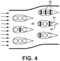
- FIG. 4 is a schematic diagram of primary passage 44 and airfoils 50 including secondary passages 64 within airfoils 50.
- the secondary passages 64 include crossbar 66.
- Crossbar 66 increases the surface area within secondary passage 64 and thereby increases the surface area shared between secondary passage 64 and airfoil 50.
- the increased surface area between secondary passage 64 and airfoil 50 increases the heat transfer between air running through primary passage 44 and fluid running through secondary passage 64.
- Crossbar 66 also provides structural support within secondary passage 64 and airfoil 50.
- all secondary passages 64 of airfoils 50 can include crossbar 66.
- crossbar 66 is a type of flow restrictor/support within secondary passages 64. Any shape, and or configuration of shapes can be used to restrict the flow of fluid and provide support within secondary passages 64.
- FIG. 5 is a cross-sectional view of an alternative design of secondary passages 64 within one of airfoils 50.
- a first secondary passage 64 a can have a first cross-sectional profile and a second secondary passage 64 b can have a second cross-sectional profile.
- the first cross-sectional profile of the first secondary passage 64 a can be different than the second cross-sectional profile of the second secondary passage 64 b .
- airfoil 50 in FIG. 5 includes third secondary passage 64 c with a third cross-sectional profile that is different than the first cross-sectional profile of first secondary passage 64 a and the second cross-sectional profile of second secondary passage 64 b .
- the first cross-sectional profile of the first secondary passage 64 a can be the same as the second cross-sectional profile of the second secondary passage 64 b .
- airfoil 50 includes internal walls 68.
- Internal walls 68 segregate and fluidically isolate first secondary passage 64 a from second secondary passage 64 b and second secondary passage 64 b from third secondary passage 64 c .
- the shape of internal walls 68 can be altered to increase the surface area between airfoil 50 and secondary passages 64.
- one of internal walls 68 can be zig-zagged shaped to increase the surface area between airfoil 50 and secondary passages 64 a and 64 b .
- internal walls 68 could be chevron shaped, corrugated, and or any other combination of shapes to increase the surface area between airfoil 50 and secondary passages 64 a , 64 b , and 64 c .
- internal walls 68 can include textures, surface imperfections, or irregularities to increase the surface area between airfoil 50 and secondary passages 64 a , 64 b , and 64 c .
Landscapes
- Engineering & Computer Science (AREA)
- Physics & Mathematics (AREA)
- Thermal Sciences (AREA)
- Mechanical Engineering (AREA)
- General Engineering & Computer Science (AREA)
- Geometry (AREA)
- Heat-Exchange Devices With Radiators And Conduit Assemblies (AREA)
- Turbine Rotor Nozzle Sealing (AREA)
Description
- This disclosure relates to a heat exchanger, and in particular, to an additively manufactured heat exchanger.
- Heat exchangers are often used to transfer heat between two fluids. For example, heat exchangers are used on aircraft to transfer heat between a relatively hot air source, e.g., bleed air from a gas turbine engine, and a relatively cool air source, e.g., ram air.
-
US 20100006276 A1 discloses a heat exchanger according to the preamble of claim 1 and describes heat exchangers that include multichannel tube and fin configurations designed to promote the release of condensate. The multichannel tubes may have a curved, round, or airfoil shape, and may be used with plate or corrugated fins. -
US 20100263847 A1 describes a microchannel heat exchanger including at least one manifold for distributing fluid and a plurality of tubes extending from the at least one manifold. -
WO 2018083423 A1 describes a heat exchanger with mechanical assembly, comprising a plurality of heat exchange elements, and a plurality of tubes mechanically assembled to the heat exchange elements, the tubes respectively comprising an outer casing delimiting a channel for the flow of a first fluid. -
JPS5221447U - According to an aspect of the invention, there is provided a heat exchanger as recited in claim 1.
- According to various embodiments, there is provided a heat exchanger as recited in any of claims 2 to 12.
- Persons of ordinary skill in the art will recognize that other aspects and embodiments of the present invention are possible in view of the entirety of the present disclosure, including the accompanying figures.
-
-
FIG. 1 is a perspective view of a heat exchanger. -
FIG. 2 is a cross-sectional view of the heat exchanger fromFIG. 1 taken along line A-A. -
FIG. 3 is another cross-sectional view of another example of a heat exchanger. -
FIG. 4 is a schematic diagram of a plurality of airfoils including a plurality of passages within a primary passage. -
FIG. 5 is a cross-sectional view of an alternative design of secondary passages. - While the above-identified drawing figures set forth one or more embodiments of the invention, other embodiments are also contemplated. In all cases, this disclosure presents the invention by way of representation and not limitation. It should be understood that numerous other modifications and embodiments can be devised by those skilled in the art, which fall within the scope and spirit of the principles of the invention. The figures may not be drawn to scale, and applications and embodiments of the present invention may include features and components not specifically shown in the drawings. Like reference numerals identify similar structural elements.
- This disclosure relates to an additively manufactured heat exchange that includes a heat exchanger core. The heat exchanger core includes a primary passage defined between a first fin and a second fin that extends through the heat exchanger core. The heat exchanger core also includes a plurality of airfoils that extend within the primary passages from the first fin to the second fin. At least one airfoil of the plurality of airfoils includes a secondary passage that extends through the heat exchanger core within the at least one airfoil transverse to the primary passage. The additively manufactured heat exchanger will be discussed in detail with reference to
FIGS. 1-5 . -
FIG. 1 is a perspective view ofheat exchanger 10.Heat exchanger 10 includesheat exchanger core 12 andheaders 70.Heat exchanger core 12 includesfirst side 20,second side 22,third side 24,fourth side 26,fifth side 28,sixth side 30, a plurality offins 39 that includesfirst fin 40 andsecond fin 42, andprimary passages 44. Each ofprimary passages 44 includesprimary inlet 46 andprimary outlet 48. One ofprimary passages 44 extends betweenfirst fin 40 andsecond fin 42.Header 70 includesinlet 72,plenum 74, and plurality of outlets 76 (hereinafter referred to as "outlets 76").Heat exchanger 10 also includes first direction A, second direction B, and third direction C. -
Second side 22 is opposite offirst side 20.Third side 24 extends fromfirst side 20 tosecond side 22.Fourth side 26 is oppositethird side 24 and extends fromfirst side 20 tosecond side 22.Fifth side 28 extends fromfirst side 20 tosecond side 22 and extends fromthird side 24 tofourth side 26.Sixth side 30 is oppositefifth side 28 and extends fromfirst side 20 tosecond side 22 and extends fromthird side 24 tofourth side 26. -
First fin 40 extends fromfirst side 20 tosecond side 22 in first direction A and extends fromfifth side 28 tosixth side 30 in second direction B.Second fin 42 extends fromfirst side 20 tosecond side 22 in first direction A and extends fromfifth side 28 tosixth side 30 in second direction B.Second fin 42 is spaced apart fromfirst fin 40 in third direction C.Primary passage 44 extends fromfirst side 20 tosecond side 22 and fromfifth side 28 andsixth side 30 betweenfirst fin 40 andsecond fin 42 fromprimary inlet 46 toprimary outlet 48.Primary inlet 46 is onfirst side 20 andprimary outlet 48 is onsecond side 22. As shown inFIG. 1 ,first fin 40 andsecond fin 42 are corrugated. The corrugation offirst fin 40 andsecond fin 42 helps to provide structural support toheat exchanger core 12 and enableheat exchanger core 12 to be additively manufactured without additional supports. In another example,first fin 40 andsecond fin 42 can have a sinusoidal, repeating chevron, or any other shape that enablesfirst fin 40 andsecond fin 42 to be additively manufactured. -
Header 70 is onthird side 24 ofheat exchanger core 12.Plenum 74 is fluidically betweeninlet 72 andoutlets 76.Outlets 76 ofheader 70 are fluidically connected to secondary passage 64 (first shown inFIG. 2 ).Header 70 can also be onfourth side 26 ofheat exchanger core 12. Whenheader 70 is onfourth side 26 ofheat exchanger core 12header 70 includesinlets 72,plenum 74 andoutlet 76.Inlet 72 are fluidically connected tosecondary passage 64 opposite ofheader 70 onthird side 24 ofheat exchanger core 12. -
FIG. 2 is a cross-sectional view of the heat exchanger fromFIG. 1 taken along line A-A. As shown inFIG. 2 ,heat exchanger core 12 includes plurality ofairfoils 50. Eachairfoil 50 in the plurality ofairfoils 50 includes leadingedge 56,trailing edge 58,pressure side 60,suction side 62, and at least onesecondary passage 64.Airfoils 50 are positioned withinprimary passage 44.Airfoils 50 include a base (not shown) onfourth side 26 and a tip (not shown) onthird side 24. Each ofairfoils 50 has a height extending from the base to the tip.Leading edge 56 extends fromfirst fin 40 tosecond fin 42 along the height of eachairfoil 50.Trailing edge 58 is opposite leadingedge 56 and extends along the height of eachairfoil 50. Eachairfoil 50 has a chord length spanning from leadingedge 56 to trailingedge 58.Pressure side 60 of eachairfoil 50 extends between leadingedge 56 andtrailing edge 58 and extends along the height of eachairfoil 50.Suction side 62 of eachairfoil 50 is opposite ofpressure side 60 and extends between leadingedge 56 andtrailing edge 58 and extends along the height of eachairfoil 50. Eachairfoil 50 has a thickness spanning frompressure side 60 tosuction side 62. Eachairfoil 50 is positioned so that leadingedge 56 facesprimary inlet 46 and trailingedge 58 facesprimary outlet 48. As shown inFIG. 2 ,suction side 62 ofairfoils 50 can facesixth side 30 andpressure side 60 ofairfoils 50 can facefifth side 28. -
Airfoils 50 are within eachprimary passage 44 to help guide the air that flows throughprimary passage 44 to limit the pressure drop throughprimary passage 44.Airfoils 50 also provide structural support throughoutheat exchanger core 12 ofheat exchanger 10 and provide a structure to housesecondary passages 64. Moreover, the airfoil shape ofairfoils 50 has a greater surface area withinprimary passage 44 than ifsecondary passages 64 were housed within simple tubes or pipes. The increased surface area ofairfoils 50 provides more heat transfer surface betweenprimary passage 44 andsecondary passage 64. Therefore, the airfoil shape ofairfoils 50 increases the heat transfer between the air flowing throughprimary passage 44 and the fluid flowing throughsecondary passage 64. - Each of
secondary passages 64 extend throughheat exchanger core 12 within one ofairfoils 50 transverseprimary passage 44. Eachsecondary passage 64 inairfoils 50 is a high-pressure passage designed to direct a high-pressure fluid throughheat exchanger core 12 ofheat exchanger 10. The fluid that flows throughsecondary passages 64 can be supercritical CO2, or any other high-pressure fluid. As shown inFIG. 2 , eachairfoil 50 can include a plurality ofsecondary passages 64 extending fromfourth side 26 tothird side 24 ofheat exchanger core 12. In other examples, eachairfoil 50 can include a singlesecondary passage 64. When eachairfoil 50 includes a plurality ofsecondary passages 64, eachpassage 64 of the plurality ofsecondary passages 64 can have a different shape. As shown inFIG. 2 , some ofsecondary passages 64 are circular, and one ofsecondary passages 64 is triangular. - In operation, a low-pressure air, e.g., between 3-15 psi, enters
heat exchanger core 12 throughprimary inlet 46. The low-pressure air flows throughprimary passage 44 betweenfirst fin 40 andsecond fin 42 and out ofheat exchanger core 12 throughprimary outlet 48. Simultaneously, a high-pressure fluid, e.g., supercritical CO2, supercritical He, or any other noble gas, and any other low, mid, and high-pressure refrigerants, flows withininlet 72 ofheader 70 and is distributed tooutlets 76 ofheader 70 viaplenum 74 ofheader 70. Each outlet ofoutlets 76 is fluidically connected to one ofsecondary passages 64. The high-pressure fluid then flows through eachsecondary passage 64 in a direction that is transverse to the low-pressure air flowing throughprimary passage 44 and leavesheat exchanger core 12 through a high-pressure fluid header. - In one example, the low-pressure air can enter
heat exchanger core 12 at a temperature greater than the temperature of the high-pressure fluid enteringheat exchanger core 12. In this example, the heat will be transferred from the low-pressure air to the high-pressure fluid acrossairfoils 50. In another example, the low-pressure air can enterheat exchanger core 12 at a temperature lower than the temperature of the high-pressure fluid enteringheat exchanger core 12. In this example, heat will be transferred from the high-pressure fluid to the low-pressure air acrossairfoils 50. - As discussed above, the shape of
first fin 40 andsecond fin 42 and the shape ofairfoils 50 aid in the additive manufacturing ofheat exchanger 10.Heat exchanger 10 can be additively manufactured in a single manufacturing process using powder bed fusion, directed energy deposition, and or any other form of additive manufacturing.Heat exchanger 10 can be additively manufactured by first formingheader 70 in a layer-by-layer process. - Next,
heat exchanger core 12 can be formed using a layer-by-layer process. As discussed above, the corrugation offirst fin 40 andsecond fin 42 helps with the additive manufacturing ofheat exchanger core 12. This is because the corrugation offirst fin 40 andsecond fin 42 is designed to prevent too much or too little hangover. For example, as shown inFIGS. 1 and2 , the corrugation has around a 45-degree angle when measured from a plane normal the build platform. Without these angles,first fin 40 andsecond fin 42 would require internal supports during additive manufacturing that would later need to be removed in an additional processing step. As discussed aboveairfoils 50 help with additivemanufacturing heat exchanger 10 becauseairfoils 50 provide internal supports throughout the layer-by layer process asairfoils 50 extend throughfirst fin 40 andsecond fin 42. Afterheat exchanger core 12 is formed using a layer-by-layer process, the other header, which can be similar toheader 70 can be formed using a layer-by-layer process. -
FIG. 3 is a cross-sectional view of another example ofheat exchanger 10. As shown inFIG. 3 , afirst airfoil 50a ofairfoils 50 can havepressure side 60 facingfifth side 28 andsuction side 62 facingsixth side 30 and asecond airfoil 50b ofairfoils 50 can havepressure side 60 facingsixth side 30 andsuction side 62 facingfifth side 28. The alternating fashion offirst airfoil 50a andsecond airfoil 50b helps minimize the resistance to flow of air flowing throughprimary passage 44. -
FIG. 4 is a schematic diagram ofprimary passage 44 andairfoils 50 includingsecondary passages 64 withinairfoils 50. As shown inFIG. 4 , at least some of thesecondary passages 64 include crossbar 66. Crossbar 66 increases the surface area withinsecondary passage 64 and thereby increases the surface area shared betweensecondary passage 64 andairfoil 50. The increased surface area betweensecondary passage 64 andairfoil 50 increases the heat transfer between air running throughprimary passage 44 and fluid running throughsecondary passage 64. Crossbar 66 also provides structural support withinsecondary passage 64 andairfoil 50. As shown inFIG. 4 , allsecondary passages 64 ofairfoils 50 can include crossbar 66. As shown inFIG. 4 , crossbar 66 is a type of flow restrictor/support withinsecondary passages 64. Any shape, and or configuration of shapes can be used to restrict the flow of fluid and provide support withinsecondary passages 64. -
FIG. 5 is a cross-sectional view of an alternative design ofsecondary passages 64 within one ofairfoils 50. As shown inFIG. 5 , a firstsecondary passage 64a can have a first cross-sectional profile and a secondsecondary passage 64b can have a second cross-sectional profile. In example shown inFIG. 5 , the first cross-sectional profile of the firstsecondary passage 64a can be different than the second cross-sectional profile of the secondsecondary passage 64b. Moreover,airfoil 50 inFIG. 5 includes thirdsecondary passage 64c with a third cross-sectional profile that is different than the first cross-sectional profile of firstsecondary passage 64a and the second cross-sectional profile of secondsecondary passage 64b. In another example, the first cross-sectional profile of the firstsecondary passage 64a can be the same as the second cross-sectional profile of the secondsecondary passage 64b. - As also shown in
FIG. 5 ,airfoil 50 includesinternal walls 68.Internal walls 68 segregate and fluidically isolate firstsecondary passage 64a from secondsecondary passage 64b and secondsecondary passage 64b from thirdsecondary passage 64c. The shape ofinternal walls 68 can be altered to increase the surface area betweenairfoil 50 andsecondary passages 64. For example, as shown inFIG. 5 , one ofinternal walls 68 can be zig-zagged shaped to increase the surface area betweenairfoil 50 andsecondary passages internal walls 68 could be chevron shaped, corrugated, and or any other combination of shapes to increase the surface area betweenairfoil 50 andsecondary passages internal walls 68 can include textures, surface imperfections, or irregularities to increase the surface area betweenairfoil 50 andsecondary passages - While the invention has been described with reference to an exemplary embodiment(s), it will be understood by those skilled in the art that various changes may be made and equivalents may be substituted for elements thereof without departing from the scope of the invention. In addition, many modifications may be made to adapt a particular situation or material to the teachings of the invention without departing from the essential scope thereof. Therefore, it is intended that the invention not be limited to the particular embodiment(s) disclosed, but that the invention will include all embodiments falling within the scope of the appended claims.
Claims (12)
- A heat exchanger (10) comprising:
a heat exchanger core (12), wherein the heat exchanger core (12) comprises:a first fin (40);a second fin (42) spaced apart from the first fin (40);a primary passage (44) defined between the first fin (40) and the second fin (42) and extending through the heat exchanger core (12); anda plurality of airfoils (50) extending through the first fin (40), the primary passage (44), and the second fin (42), wherein at least one airfoil of the plurality of airfoils (50) comprises:a secondary passage (64), wherein the secondary passage (64) extends through the heat exchanger core (12) within the at least one airfoil transverse to the primary passage (44); andcharacterised by a crossbar (66) within the secondary passage (64). - The heat exchanger (10) of claim 1, wherein the heat exchanger core (12) further comprises:a first side (20);a second side (22) opposite the first side (20);a third side (24) extending from the first side (20) to the second side (22);a fourth side (26) opposite the third side (24) and extending from the first side (20) to the second side (22);a fifth side (28) extending from the first side (20) to the second side (22) and extending from the third side (24) to the fourth side (26); anda sixth side (30) opposite the fifth side (28) extending from the first side (20) to the second side (22) and extending from the third side (24) to the fourth side (26),wherein the first fin (40) and the second fin (42) both extend from the first side (20) to the second side (22) and extend from the fifth side (28) to the sixth side (30), andwherein the primary passage (44) extends from the first side (20) to the second side (22) and from the fifth side (28) to the sixth side (30).
- The heat exchanger (10) of claim 2, wherein the heat exchanger core (12) comprises:a primary inlet (46) on the first side (20) of the heat exchanger core (12); anda primary outlet (48) on the second side (22) of the heat exchanger core (12), wherein the primary passage (44) extends from the primary inlet (46) to the primary outlet (48).
- The heat exchanger (10) of claim 2 or 3, wherein each of the plurality of airfoils (50) comprises:a base at the fourth side (26) of the heat exchanger core (12);a tip at the third side (24) of the heat exchanger core (12); anda height spanning from the base to the tip.
- The heat exchanger (10) of claim 4, wherein each of the plurality of airfoils (50) comprises:a leading edge (56) extending along the height of each airfoil of the plurality of airfoils (50);a trailing edge (58) opposite the leading edge (56) and extending along the height of each airfoil of the plurality of airfoils (50); anda chord length spanning from the leading edge (56) to the trailing edge (58).
- The heat exchanger (10) of claim 5, wherein each of the plurality of airfoils (50) comprises:a pressure side (60) extending between the leading edge (56) and the trailing edge (58) and extending along the height of each airfoil of the plurality of airfoils (50);a suction side (62) opposite the pressure side (60) and extending between the leading edge (56) and the trailing edge (58) and extending along the height of each airfoil of the plurality of airfoils (50); anda thickness spanning from the pressure side (60) to the suction side (62).
- The heat exchanger (10) of claim 6, when dependent on claim 3, wherein each of the plurality of airfoils (50) is positioned so that the leading edge (56) faces the primary inlet (46) and the trailing edge (58) faces the primary outlet (48).
- The heat exchanger (10) of any of claims 2 to 7, wherein the heat exchanger (10) further comprises:
a header (70) on the third side (24) of the heat exchanger core (12), wherein the
header (70) comprises:an inlet (72);a plenum (74); andan outlet (76), wherein the plenum (74) is fluidically between the inlet (72) of the header (70) and the outlet of the header (70), and the outlet (76) of the header (70) is fluidically connected to the secondary passage (64). - The heat exchanger (10) of any of claims 2 to 8, wherein the first fin (40) and the second fin (42) are corrugated.
- The heat exchanger (10) of any of claims 2 to 5, wherein a first airfoil of the plurality of airfoils (50) has a pressure side (60) facing the fifth side (28) and a suction side (62) facing the sixth side (30), and a second airfoil of the plurality of airfoils (50) has a pressure side (60) facing the sixth side (30) and a suction side (62) facing the fifth side (28).
- The heat exchanger (10) of any of claims 2 to 10, wherein each airfoil of the plurality of airfoils (50) comprises: a plurality of secondary passages (64), wherein the plurality of secondary passages (64) comprises: a first secondary passage (64a) with a first cross-sectional profile; and a second secondary passage (64b) with a second cross-sectional profile, wherein the second cross-sectional profile is different from the first cross-sectional profile.
- The heat exchanger (10) of claim 11, wherein each airfoil of the plurality of airfoils (50) further comprises: an internal wall (68) segregating the first secondary passage (64a) from the second secondary passage (64b), wherein the internal wall (68) comprises a zig-zag profile.
Applications Claiming Priority (1)
| Application Number | Priority Date | Filing Date | Title |
|---|---|---|---|
| US17/644,017 US11988461B2 (en) | 2021-12-13 | 2021-12-13 | Additive airfoil heat exchanger |
Publications (2)
| Publication Number | Publication Date |
|---|---|
| EP4194786A1 EP4194786A1 (en) | 2023-06-14 |
| EP4194786B1 true EP4194786B1 (en) | 2024-08-21 |
Family
ID=84488602
Family Applications (1)
| Application Number | Title | Priority Date | Filing Date |
|---|---|---|---|
| EP22212890.2A Active EP4194786B1 (en) | 2021-12-13 | 2022-12-12 | Additive airfoil heat exchanger |
Country Status (2)
| Country | Link |
|---|---|
| US (1) | US11988461B2 (en) |
| EP (1) | EP4194786B1 (en) |
Families Citing this family (1)
| Publication number | Priority date | Publication date | Assignee | Title |
|---|---|---|---|---|
| US12275089B2 (en) * | 2022-05-20 | 2025-04-15 | Hamilton Sundstrand Corporation | Additively manufactured heat exchanger with special surface roughness |
Family Cites Families (18)
| Publication number | Priority date | Publication date | Assignee | Title |
|---|---|---|---|---|
| US1958364A (en) | 1931-08-26 | 1934-05-08 | Indian Refining Co | Heat transfer tube |
| US3885936A (en) | 1972-03-01 | 1975-05-27 | Lund Basil Gilbert Alfred | Heat exchangers |
| JPS5221447U (en) | 1975-08-04 | 1977-02-15 | ||
| DE3310061A1 (en) * | 1982-11-19 | 1984-05-24 | MTU Motoren- und Turbinen-Union München GmbH, 8000 München | METHOD FOR PRODUCING A PIPE DISTRIBUTOR ARRANGEMENT AND A HEAT EXCHANGER TANK PRODUCED BY THIS METHOD |
| DE3329202A1 (en) * | 1983-08-12 | 1985-02-21 | MTU Motoren- und Turbinen-Union München GmbH, 8000 München | PROFILE TUBE HEAT EXCHANGER |
| DE3610618A1 (en) * | 1986-03-29 | 1987-10-01 | Mtu Muenchen Gmbh | PROFILE TUBE WITH ELLIPTICAL OR LANZETT-SHAPED SECTION FOR TUBE HEAT EXCHANGER AND METHOD FOR THE PRODUCTION THEREOF |
| DE4201791A1 (en) * | 1991-06-20 | 1993-07-29 | Thermal Waerme Kaelte Klima | FLAT TUBES FOR INSTALLATION IN A FLAT TUBE HEAT EXCHANGER AND METHOD FOR SEPARATING THE FLAT TUBES |
| US5172476A (en) * | 1991-08-14 | 1992-12-22 | General Motors Corporation | Method of manufacturing heat exchanger tubing |
| US5604982A (en) * | 1995-06-05 | 1997-02-25 | General Motors Corporation | Method for mechanically expanding elliptical tubes |
| US6302197B1 (en) * | 1999-12-22 | 2001-10-16 | Isteon Global Technologies, Inc. | Louvered plastic heat exchanger |
| US20100006276A1 (en) * | 2008-07-11 | 2010-01-14 | Johnson Controls Technology Company | Multichannel Heat Exchanger |
| US8234881B2 (en) * | 2008-08-28 | 2012-08-07 | Johnson Controls Technology Company | Multichannel heat exchanger with dissimilar flow |
| US9255745B2 (en) | 2009-01-05 | 2016-02-09 | Hamilton Sundstrand Corporation | Heat exchanger |
| US20100263847A1 (en) | 2009-04-21 | 2010-10-21 | Hamilton Sundstrand Corporation | Microchannel heat exchanger |
| CN101995115B (en) * | 2009-08-07 | 2014-07-23 | 江森自控科技公司 | Multi-channel heat exchanger fins |
| US9267737B2 (en) * | 2010-06-29 | 2016-02-23 | Johnson Controls Technology Company | Multichannel heat exchangers employing flow distribution manifolds |
| WO2018003091A1 (en) | 2016-06-30 | 2018-01-04 | 三菱電機株式会社 | Heat exchanger and refrigeration cycle apparatus provided with same |
| FR3061953B1 (en) | 2016-11-03 | 2019-09-13 | Valeo Systemes Thermiques | THERMAL EXCHANGER AND ASSOCIATED TUBE |
-
2021
- 2021-12-13 US US17/644,017 patent/US11988461B2/en active Active
-
2022
- 2022-12-12 EP EP22212890.2A patent/EP4194786B1/en active Active
Also Published As
| Publication number | Publication date |
|---|---|
| EP4194786A1 (en) | 2023-06-14 |
| US20230184496A1 (en) | 2023-06-15 |
| US11988461B2 (en) | 2024-05-21 |
Similar Documents
| Publication | Publication Date | Title |
|---|---|---|
| EP3789719B1 (en) | Heat exchanger with radially converging manifold | |
| KR102348770B1 (en) | Contoured wall heat exchanger | |
| US11215405B2 (en) | Heat exchanger with non-orthogonal perforations | |
| US12025387B2 (en) | Turning vanes and heat exchangers and methods of making the same | |
| US20220282931A1 (en) | Heat exchanger device | |
| EP2810010B1 (en) | Multiple tube bank heat exchanger assembly and fabrication method | |
| EP2810014B1 (en) | Method for fabricating flattened tube finned heat exchanger | |
| US12038236B2 (en) | Fractal heat exchanger | |
| EP3196584B1 (en) | Heat exchanger with adjacent inlets and outlets | |
| EP3553446B1 (en) | Shaped leading edge of cast plate fin heat exchanger | |
| US9845729B2 (en) | Method of manufacturing recuperator air cells | |
| US20100263847A1 (en) | Microchannel heat exchanger | |
| EP4194786A1 (en) | Additive airfoil heat exchanger | |
| EP3176533B1 (en) | Cross flow ceramic heat exchanger and method for manufacturing | |
| EP4141370B1 (en) | Fractal optimized core shape (addmfg) | |
| EP2997322B1 (en) | Method for manufacturing a multiple manifold assembly having internal communication ports | |
| US11187470B2 (en) | Plate fin crossflow heat exchanger | |
| EP3043138B1 (en) | Heat exchanger with fin wave control | |
| RU2659677C1 (en) | Plate heat exchanger and the plate heat exchanger manufacturing method | |
| EP4477981B1 (en) | Heat exchanger core design | |
| EP3809081A1 (en) | A heat exchanger | |
| CN113720176A (en) | Micro-channel heat exchanger with secondary fins |
Legal Events
| Date | Code | Title | Description |
|---|---|---|---|
| PUAI | Public reference made under article 153(3) epc to a published international application that has entered the european phase |
Free format text: ORIGINAL CODE: 0009012 |
|
| STAA | Information on the status of an ep patent application or granted ep patent |
Free format text: STATUS: THE APPLICATION HAS BEEN PUBLISHED |
|
| AK | Designated contracting states |
Kind code of ref document: A1 Designated state(s): AL AT BE BG CH CY CZ DE DK EE ES FI FR GB GR HR HU IE IS IT LI LT LU LV MC ME MK MT NL NO PL PT RO RS SE SI SK SM TR |
|
| STAA | Information on the status of an ep patent application or granted ep patent |
Free format text: STATUS: REQUEST FOR EXAMINATION WAS MADE |
|
| 17P | Request for examination filed |
Effective date: 20231214 |
|
| RBV | Designated contracting states (corrected) |
Designated state(s): AL AT BE BG CH CY CZ DE DK EE ES FI FR GB GR HR HU IE IS IT LI LT LU LV MC ME MK MT NL NO PL PT RO RS SE SI SK SM TR |
|
| GRAP | Despatch of communication of intention to grant a patent |
Free format text: ORIGINAL CODE: EPIDOSNIGR1 |
|
| STAA | Information on the status of an ep patent application or granted ep patent |
Free format text: STATUS: GRANT OF PATENT IS INTENDED |
|
| INTG | Intention to grant announced |
Effective date: 20240326 |
|
| RIN1 | Information on inventor provided before grant (corrected) |
Inventor name: ALAHYARI, ABBAS A. Inventor name: KIRSCH, KATHRYN L. Inventor name: MACDONALD, MALCOLM |
|
| GRAS | Grant fee paid |
Free format text: ORIGINAL CODE: EPIDOSNIGR3 |
|
| GRAA | (expected) grant |
Free format text: ORIGINAL CODE: 0009210 |
|
| STAA | Information on the status of an ep patent application or granted ep patent |
Free format text: STATUS: THE PATENT HAS BEEN GRANTED |
|
| AK | Designated contracting states |
Kind code of ref document: B1 Designated state(s): AL AT BE BG CH CY CZ DE DK EE ES FI FR GB GR HR HU IE IS IT LI LT LU LV MC ME MK MT NL NO PL PT RO RS SE SI SK SM TR |
|
| REG | Reference to a national code |
Ref country code: GB Ref legal event code: FG4D |
|
| REG | Reference to a national code |
Ref country code: CH Ref legal event code: EP |
|
| REG | Reference to a national code |
Ref country code: IE Ref legal event code: FG4D |
|
| REG | Reference to a national code |
Ref country code: DE Ref legal event code: R096 Ref document number: 602022005493 Country of ref document: DE |
|
| REG | Reference to a national code |
Ref country code: LT Ref legal event code: MG9D |
|
| REG | Reference to a national code |
Ref country code: NL Ref legal event code: MP Effective date: 20240821 |
|
| PG25 | Lapsed in a contracting state [announced via postgrant information from national office to epo] |
Ref country code: NO Free format text: LAPSE BECAUSE OF FAILURE TO SUBMIT A TRANSLATION OF THE DESCRIPTION OR TO PAY THE FEE WITHIN THE PRESCRIBED TIME-LIMIT Effective date: 20241121 |
|
| REG | Reference to a national code |
Ref country code: AT Ref legal event code: MK05 Ref document number: 1715859 Country of ref document: AT Kind code of ref document: T Effective date: 20240821 |
|
| PG25 | Lapsed in a contracting state [announced via postgrant information from national office to epo] |
Ref country code: NL Free format text: LAPSE BECAUSE OF FAILURE TO SUBMIT A TRANSLATION OF THE DESCRIPTION OR TO PAY THE FEE WITHIN THE PRESCRIBED TIME-LIMIT Effective date: 20240821 Ref country code: PL Free format text: LAPSE BECAUSE OF FAILURE TO SUBMIT A TRANSLATION OF THE DESCRIPTION OR TO PAY THE FEE WITHIN THE PRESCRIBED TIME-LIMIT Effective date: 20240821 Ref country code: GR Free format text: LAPSE BECAUSE OF FAILURE TO SUBMIT A TRANSLATION OF THE DESCRIPTION OR TO PAY THE FEE WITHIN THE PRESCRIBED TIME-LIMIT Effective date: 20241122 Ref country code: FI Free format text: LAPSE BECAUSE OF FAILURE TO SUBMIT A TRANSLATION OF THE DESCRIPTION OR TO PAY THE FEE WITHIN THE PRESCRIBED TIME-LIMIT Effective date: 20240821 Ref country code: PT Free format text: LAPSE BECAUSE OF FAILURE TO SUBMIT A TRANSLATION OF THE DESCRIPTION OR TO PAY THE FEE WITHIN THE PRESCRIBED TIME-LIMIT Effective date: 20241223 |
|
| PG25 | Lapsed in a contracting state [announced via postgrant information from national office to epo] |
Ref country code: BG Free format text: LAPSE BECAUSE OF FAILURE TO SUBMIT A TRANSLATION OF THE DESCRIPTION OR TO PAY THE FEE WITHIN THE PRESCRIBED TIME-LIMIT Effective date: 20240821 |
|
| PG25 | Lapsed in a contracting state [announced via postgrant information from national office to epo] |
Ref country code: LV Free format text: LAPSE BECAUSE OF FAILURE TO SUBMIT A TRANSLATION OF THE DESCRIPTION OR TO PAY THE FEE WITHIN THE PRESCRIBED TIME-LIMIT Effective date: 20240821 |
|
| PG25 | Lapsed in a contracting state [announced via postgrant information from national office to epo] |
Ref country code: AT Free format text: LAPSE BECAUSE OF FAILURE TO SUBMIT A TRANSLATION OF THE DESCRIPTION OR TO PAY THE FEE WITHIN THE PRESCRIBED TIME-LIMIT Effective date: 20240821 Ref country code: IS Free format text: LAPSE BECAUSE OF FAILURE TO SUBMIT A TRANSLATION OF THE DESCRIPTION OR TO PAY THE FEE WITHIN THE PRESCRIBED TIME-LIMIT Effective date: 20241221 |
|
| PG25 | Lapsed in a contracting state [announced via postgrant information from national office to epo] |
Ref country code: HR Free format text: LAPSE BECAUSE OF FAILURE TO SUBMIT A TRANSLATION OF THE DESCRIPTION OR TO PAY THE FEE WITHIN THE PRESCRIBED TIME-LIMIT Effective date: 20240821 |
|
| PG25 | Lapsed in a contracting state [announced via postgrant information from national office to epo] |
Ref country code: ES Free format text: LAPSE BECAUSE OF FAILURE TO SUBMIT A TRANSLATION OF THE DESCRIPTION OR TO PAY THE FEE WITHIN THE PRESCRIBED TIME-LIMIT Effective date: 20240821 Ref country code: RS Free format text: LAPSE BECAUSE OF FAILURE TO SUBMIT A TRANSLATION OF THE DESCRIPTION OR TO PAY THE FEE WITHIN THE PRESCRIBED TIME-LIMIT Effective date: 20241121 |
|
| PG25 | Lapsed in a contracting state [announced via postgrant information from national office to epo] |
Ref country code: RS Free format text: LAPSE BECAUSE OF FAILURE TO SUBMIT A TRANSLATION OF THE DESCRIPTION OR TO PAY THE FEE WITHIN THE PRESCRIBED TIME-LIMIT Effective date: 20241121 Ref country code: PT Free format text: LAPSE BECAUSE OF FAILURE TO SUBMIT A TRANSLATION OF THE DESCRIPTION OR TO PAY THE FEE WITHIN THE PRESCRIBED TIME-LIMIT Effective date: 20241223 Ref country code: PL Free format text: LAPSE BECAUSE OF FAILURE TO SUBMIT A TRANSLATION OF THE DESCRIPTION OR TO PAY THE FEE WITHIN THE PRESCRIBED TIME-LIMIT Effective date: 20240821 Ref country code: NO Free format text: LAPSE BECAUSE OF FAILURE TO SUBMIT A TRANSLATION OF THE DESCRIPTION OR TO PAY THE FEE WITHIN THE PRESCRIBED TIME-LIMIT Effective date: 20241121 Ref country code: NL Free format text: LAPSE BECAUSE OF FAILURE TO SUBMIT A TRANSLATION OF THE DESCRIPTION OR TO PAY THE FEE WITHIN THE PRESCRIBED TIME-LIMIT Effective date: 20240821 Ref country code: LV Free format text: LAPSE BECAUSE OF FAILURE TO SUBMIT A TRANSLATION OF THE DESCRIPTION OR TO PAY THE FEE WITHIN THE PRESCRIBED TIME-LIMIT Effective date: 20240821 Ref country code: IS Free format text: LAPSE BECAUSE OF FAILURE TO SUBMIT A TRANSLATION OF THE DESCRIPTION OR TO PAY THE FEE WITHIN THE PRESCRIBED TIME-LIMIT Effective date: 20241221 Ref country code: HR Free format text: LAPSE BECAUSE OF FAILURE TO SUBMIT A TRANSLATION OF THE DESCRIPTION OR TO PAY THE FEE WITHIN THE PRESCRIBED TIME-LIMIT Effective date: 20240821 Ref country code: GR Free format text: LAPSE BECAUSE OF FAILURE TO SUBMIT A TRANSLATION OF THE DESCRIPTION OR TO PAY THE FEE WITHIN THE PRESCRIBED TIME-LIMIT Effective date: 20241122 Ref country code: FI Free format text: LAPSE BECAUSE OF FAILURE TO SUBMIT A TRANSLATION OF THE DESCRIPTION OR TO PAY THE FEE WITHIN THE PRESCRIBED TIME-LIMIT Effective date: 20240821 Ref country code: ES Free format text: LAPSE BECAUSE OF FAILURE TO SUBMIT A TRANSLATION OF THE DESCRIPTION OR TO PAY THE FEE WITHIN THE PRESCRIBED TIME-LIMIT Effective date: 20240821 Ref country code: BG Free format text: LAPSE BECAUSE OF FAILURE TO SUBMIT A TRANSLATION OF THE DESCRIPTION OR TO PAY THE FEE WITHIN THE PRESCRIBED TIME-LIMIT Effective date: 20240821 Ref country code: AT Free format text: LAPSE BECAUSE OF FAILURE TO SUBMIT A TRANSLATION OF THE DESCRIPTION OR TO PAY THE FEE WITHIN THE PRESCRIBED TIME-LIMIT Effective date: 20240821 |
|
| PG25 | Lapsed in a contracting state [announced via postgrant information from national office to epo] |
Ref country code: DK Free format text: LAPSE BECAUSE OF FAILURE TO SUBMIT A TRANSLATION OF THE DESCRIPTION OR TO PAY THE FEE WITHIN THE PRESCRIBED TIME-LIMIT Effective date: 20240821 Ref country code: RO Free format text: LAPSE BECAUSE OF FAILURE TO SUBMIT A TRANSLATION OF THE DESCRIPTION OR TO PAY THE FEE WITHIN THE PRESCRIBED TIME-LIMIT Effective date: 20240821 Ref country code: SM Free format text: LAPSE BECAUSE OF FAILURE TO SUBMIT A TRANSLATION OF THE DESCRIPTION OR TO PAY THE FEE WITHIN THE PRESCRIBED TIME-LIMIT Effective date: 20240821 |
|
| PG25 | Lapsed in a contracting state [announced via postgrant information from national office to epo] |
Ref country code: EE Free format text: LAPSE BECAUSE OF FAILURE TO SUBMIT A TRANSLATION OF THE DESCRIPTION OR TO PAY THE FEE WITHIN THE PRESCRIBED TIME-LIMIT Effective date: 20240821 |
|
| PG25 | Lapsed in a contracting state [announced via postgrant information from national office to epo] |
Ref country code: CZ Free format text: LAPSE BECAUSE OF FAILURE TO SUBMIT A TRANSLATION OF THE DESCRIPTION OR TO PAY THE FEE WITHIN THE PRESCRIBED TIME-LIMIT Effective date: 20240821 |
|
| PG25 | Lapsed in a contracting state [announced via postgrant information from national office to epo] |
Ref country code: SK Free format text: LAPSE BECAUSE OF FAILURE TO SUBMIT A TRANSLATION OF THE DESCRIPTION OR TO PAY THE FEE WITHIN THE PRESCRIBED TIME-LIMIT Effective date: 20240821 Ref country code: IT Free format text: LAPSE BECAUSE OF FAILURE TO SUBMIT A TRANSLATION OF THE DESCRIPTION OR TO PAY THE FEE WITHIN THE PRESCRIBED TIME-LIMIT Effective date: 20240821 |
|
| REG | Reference to a national code |
Ref country code: DE Ref legal event code: R097 Ref document number: 602022005493 Country of ref document: DE |
|
| PLBE | No opposition filed within time limit |
Free format text: ORIGINAL CODE: 0009261 |
|
| STAA | Information on the status of an ep patent application or granted ep patent |
Free format text: STATUS: NO OPPOSITION FILED WITHIN TIME LIMIT |
|
| PG25 | Lapsed in a contracting state [announced via postgrant information from national office to epo] |
Ref country code: MC Free format text: LAPSE BECAUSE OF FAILURE TO SUBMIT A TRANSLATION OF THE DESCRIPTION OR TO PAY THE FEE WITHIN THE PRESCRIBED TIME-LIMIT Effective date: 20240821 |
|
| 26N | No opposition filed |
Effective date: 20250522 |
|
| PG25 | Lapsed in a contracting state [announced via postgrant information from national office to epo] |
Ref country code: LU Free format text: LAPSE BECAUSE OF NON-PAYMENT OF DUE FEES Effective date: 20241212 |
|
| PG25 | Lapsed in a contracting state [announced via postgrant information from national office to epo] |
Ref country code: SE Free format text: LAPSE BECAUSE OF FAILURE TO SUBMIT A TRANSLATION OF THE DESCRIPTION OR TO PAY THE FEE WITHIN THE PRESCRIBED TIME-LIMIT Effective date: 20240821 |
|
| REG | Reference to a national code |
Ref country code: BE Ref legal event code: MM Effective date: 20241231 |
|
| PG25 | Lapsed in a contracting state [announced via postgrant information from national office to epo] |
Ref country code: BE Free format text: LAPSE BECAUSE OF NON-PAYMENT OF DUE FEES Effective date: 20241231 |
|
| PG25 | Lapsed in a contracting state [announced via postgrant information from national office to epo] |
Ref country code: IE Free format text: LAPSE BECAUSE OF NON-PAYMENT OF DUE FEES Effective date: 20241212 |
|
| PGFP | Annual fee paid to national office [announced via postgrant information from national office to epo] |
Ref country code: DE Payment date: 20251126 Year of fee payment: 4 |
|
| PGFP | Annual fee paid to national office [announced via postgrant information from national office to epo] |
Ref country code: FR Payment date: 20251120 Year of fee payment: 4 |
|
| PG25 | Lapsed in a contracting state [announced via postgrant information from national office to epo] |
Ref country code: CY Free format text: LAPSE BECAUSE OF FAILURE TO SUBMIT A TRANSLATION OF THE DESCRIPTION OR TO PAY THE FEE WITHIN THE PRESCRIBED TIME-LIMIT Effective date: 20240821 |
|
| PG25 | Lapsed in a contracting state [announced via postgrant information from national office to epo] |
Ref country code: TR Free format text: LAPSE BECAUSE OF FAILURE TO SUBMIT A TRANSLATION OF THE DESCRIPTION OR TO PAY THE FEE WITHIN THE PRESCRIBED TIME-LIMIT Effective date: 20240821 |
|
| PG25 | Lapsed in a contracting state [announced via postgrant information from national office to epo] |
Ref country code: HU Free format text: LAPSE BECAUSE OF FAILURE TO SUBMIT A TRANSLATION OF THE DESCRIPTION OR TO PAY THE FEE WITHIN THE PRESCRIBED TIME-LIMIT; INVALID AB INITIO Effective date: 20221212 |
|
| PG25 | Lapsed in a contracting state [announced via postgrant information from national office to epo] |
Ref country code: SI Free format text: LAPSE BECAUSE OF FAILURE TO SUBMIT A TRANSLATION OF THE DESCRIPTION OR TO PAY THE FEE WITHIN THE PRESCRIBED TIME-LIMIT Effective date: 20240821 |
|
| PG25 | Lapsed in a contracting state [announced via postgrant information from national office to epo] |
Ref country code: ME Free format text: LAPSE BECAUSE OF FAILURE TO SUBMIT A TRANSLATION OF THE DESCRIPTION OR TO PAY THE FEE WITHIN THE PRESCRIBED TIME-LIMIT Effective date: 20240821 |
|
| PG25 | Lapsed in a contracting state [announced via postgrant information from national office to epo] |
Ref country code: LT Free format text: LAPSE BECAUSE OF FAILURE TO SUBMIT A TRANSLATION OF THE DESCRIPTION OR TO PAY THE FEE WITHIN THE PRESCRIBED TIME-LIMIT Effective date: 20240821 |
|
| REG | Reference to a national code |
Ref country code: CH Ref legal event code: H13 Free format text: ST27 STATUS EVENT CODE: U-0-0-H10-H13 (AS PROVIDED BY THE NATIONAL OFFICE) Effective date: 20260723 |