EP4194618A1 - Stop instruction system - Google Patents
Stop instruction system Download PDFInfo
- Publication number
- EP4194618A1 EP4194618A1 EP21872100.9A EP21872100A EP4194618A1 EP 4194618 A1 EP4194618 A1 EP 4194618A1 EP 21872100 A EP21872100 A EP 21872100A EP 4194618 A1 EP4194618 A1 EP 4194618A1
- Authority
- EP
- European Patent Office
- Prior art keywords
- carrier
- threshold value
- distance
- work machine
- stop instruction
- Prior art date
- Legal status (The legal status is an assumption and is not a legal conclusion. Google has not performed a legal analysis and makes no representation as to the accuracy of the status listed.)
- Granted
Links
Images




Classifications
-
- E—FIXED CONSTRUCTIONS
- E02—HYDRAULIC ENGINEERING; FOUNDATIONS; SOIL SHIFTING
- E02F—DREDGING; SOIL-SHIFTING
- E02F9/00—Component parts of dredgers or soil-shifting machines, not restricted to one of the kinds covered by groups E02F3/00 - E02F7/00
- E02F9/26—Indicating devices
- E02F9/261—Surveying the work-site to be treated
- E02F9/262—Surveying the work-site to be treated with follow-up actions to control the work tool, e.g. controller
-
- E—FIXED CONSTRUCTIONS
- E02—HYDRAULIC ENGINEERING; FOUNDATIONS; SOIL SHIFTING
- E02F—DREDGING; SOIL-SHIFTING
- E02F9/00—Component parts of dredgers or soil-shifting machines, not restricted to one of the kinds covered by groups E02F3/00 - E02F7/00
- E02F9/20—Drives; Control devices
- E02F9/2025—Particular purposes of control systems not otherwise provided for
- E02F9/2033—Limiting the movement of frames or implements, e.g. to avoid collision between implements and the cabin
-
- E—FIXED CONSTRUCTIONS
- E02—HYDRAULIC ENGINEERING; FOUNDATIONS; SOIL SHIFTING
- E02F—DREDGING; SOIL-SHIFTING
- E02F3/00—Dredgers; Soil-shifting machines
- E02F3/04—Dredgers; Soil-shifting machines mechanically-driven
- E02F3/28—Dredgers; Soil-shifting machines mechanically-driven with digging tools mounted on a dipper- or bucket-arm, i.e. there is either one arm or a pair of arms, e.g. dippers, buckets
- E02F3/36—Component parts
- E02F3/42—Drives for dippers, buckets, dipper-arms or bucket-arms
- E02F3/43—Control of dipper or bucket position; Control of sequence of drive operations
- E02F3/435—Control of dipper or bucket position; Control of sequence of drive operations for dipper-arms, backhoes or the like
- E02F3/439—Automatic repositioning of the implement, e.g. automatic dumping, auto-return
Definitions
- the present invention relates to a stop instruction system that issues an instruction to stop a carrier approaching a work machine.
- Patent Literature 1 and the like disclose a technique of stopping a carrier at a target stop position.
- a driving vehicle is stopped (see paragraph 0054, FIG. 1 , and the like of Patent Literature 1).
- Patent Literature 1 JP 2020-60032 A
- An object of the present invention is to provide a stop instruction system capable of issuing a stop instruction to stop a carrier at a timing when a position of the carrier relative to a work machine becomes appropriate.
- the stop instruction system issues an instruction to stop the carrier approaching the work machine.
- the stop instruction system includes a distance detection unit, a stop instruction output unit, and a controller.
- the distance detection unit detects a distance of the carrier from the work machine.
- the stop instruction output unit outputs a stop instruction as the instruction to stop the carrier.
- the distance detection unit detects a first distance and a second distance.
- the first distance is a distance from a specific reference position associated with the work machine to a portion of a platform of the carrier on a carrier rear side.
- the second distance is a distance from the reference position to a portion of the platform on a carrier front side.
- a first threshold value as a threshold value related to the first distance and a second threshold value as a threshold value related to the second distance are set in the controller.
- the controller causes the stop instruction output unit to output a stop instruction at least either when the first distance falls from a value greater than a first threshold value to a value equal to or smaller than the first threshold value or when the second distance falls from a value greater than a second threshold value to a value equal to or smaller than the second threshold value.
- a carrier 10, a work machine 20, and a stop instruction system 30 shown in FIG. 1 will be described with reference to FIGS. 1 to 6 .
- the carrier 10 is a vehicle including a platform 13.
- the carrier 10 is a vehicle that transports a conveyance object loaded by the work machine 20.
- the carrier 10 may be a dump car or a truck.
- the carrier 10 includes a carrier body 11 and the platform 13.
- the carrier body 11 can travel and supports the platform 13.
- the carrier body 11 includes a carrier cab 11a.
- the platform 13 accommodates a conveyance object.
- the conveyance object accommodated in the platform 13 may be, for example, earth and sand, stones, a waste, or the like.
- a carrier front rear direction U shown in FIG. 1 is a front rear direction of the carrier 10.
- a side facing from the platform 13 toward the carrier cab 11a is defined as a carrier front side U1 in the carrier front rear direction U
- a side facing from the carrier cab 11a toward the platform 13 is defined as a carrier rear side U2 in the carrier front rear direction U.
- the platform 13 may be movable with respect to the carrier body 11 or may be fixed to the carrier body 11.
- the platform 13 includes a platform floor 13a, a platform rear portion 13b, and a platform front portion 13d.
- the platform floor 13a is a portion constituting a bottom of the platform 13.
- the platform rear portion 13b is a portion (for example, an end) of the platform 13 on the carrier rear side U2.
- the platform rear portion 13b protrudes upward from a portion of the platform floor 13a on the carrier rear side U2 and has, for example, a plate shape (gate board).
- the platform rear portion 13b has a flat surface or a substantially flat surface extending in a direction orthogonal or substantially orthogonal to the carrier front rear direction U.
- the platform front portion 13d is a portion of the platform 13 on the carrier front side U1.
- the platform front portion 13d protrudes upward from a portion of the platform floor 13a on the carrier front side U1 and has, for example, a plate shape (gateway).
- the platform front portion 13d protrudes higher than the platform rear portion 13b.
- the platform front portion 13d has a flat surface or a substantially flat surface extending in a direction orthogonal or substantially orthogonal to the carrier
- the work machine 20 is a machine that performs work, for example, a construction machine that performs construction work, for example, an excavator.
- the work machine 20 captures a conveyance object (for example, excavating earth and sand) and loads the captured conveyance object onto the carrier 10 (for example, removes soil).
- the work machine 20 includes a lower travelling body 21, an upper slewing body 23, and an attachment 25.
- the lower travelling body 21 causes the work machine 20 to travel.
- the lower travelling body 21 includes, for example, left and right crawlers 21c and 21c (see FIG. 5 ).
- the upper slewing body 23 is mounted on the lower travelling body 21 so as to be able to slew.
- the attachment 25 is mounted on the upper slewing body 23 so as to be raised and lowered.
- the attachment 25 includes a boom 25a, an arm 25b, and a distal end attachment 25c.
- the boom 25a is mounted on the upper slewing body 23 so as to be raised and lowered (rotatable up and down).
- the arm 25b is rotatably attached to the boom 25a (so as to be pushed and pulled).
- the distal end attachment 25c is provided at a distal end of the attachment 25 and is rotatably attached to the arm 25b.
- the distal end attachment 25c may be a bucket that scoops a conveyance object (for example, earth and sand) or a device (for example, a grapple) that pinches and holds the conveyance obj ect.
- a direction in which a rotation axis of slewing of the upper slewing body 23 with respect to the lower travelling body 21 extends is defined as an up down direction of the work machine 20.
- a work machine front rear direction X shown in FIG. 1 is a front rear direction of the work machine 20.
- a side toward which the attachment 25 protrudes from the upper slewing body 23 is defined as a work machine front side X1 in the work machine front rear direction X, the work machine front side X1 being a direction orthogonal to the up down direction of the work machine 20, and the opposite side is defined as a work machine rear side X2 in the work machine front rear direction X.
- the stop instruction system 30 is a system (for example, an automatic horn sounding system) that automatically issues a stop instruction to stop the carrier 10 approaching the work machine 20.
- the stop instruction system 30 includes a distance detection unit 41, a carrier speed detection unit 42, a lower travelling body orientation detection unit 43, an attachment orientation detection unit 44, a stop instruction output unit 47, and a controller 50.
- the distance detection unit 41 detects a distance of the carrier 10 from the work machine 20 shown in FIG. 1 .
- the distance detection unit 41 detects a first distance L1 and a second distance L2.
- the first distance L1 is a distance (for example, the shortest distance) from a specific reference position 20a associated with the work machine 20 to the platform rear portion 13b of the carrier 10.
- the reference position 20a is, for example, a position uniquely determined from the position of the upper slewing body 23, and may be, for example, a proximal end of the boom 25a (an end close to the upper slewing body 23), or may be a specific point on a central axis of slewing of the upper slewing body 23 with respect to the lower travelling body 21.
- the second distance L2 is a distance (for example, the shortest distance) from the reference position 20a to the platform front portion 13d.
- the distance detection unit 41 may be able to detect the position of the carrier 10 relative to the work machine 20. Specifically, the distance detection unit 41 may detect three-dimensional position information of the carrier 10 and detect three-dimensional shape information of the carrier 10. In this case, the distance detection unit 41 acquires an image (distance image) having distance information (depth information). The distance detection unit 41 may detect the position of the carrier 10 based on three-dimensional information and two-dimensional information (image).
- the distance detection unit 41 may detect the position (three-dimensional position information) of only a part of the carrier 10, and for example, may detect the position of only the platform 13 of the carrier 10. Only one distance detection unit 41 may be provided, or a plurality of distance detection units 41 may be provided.
- the distance detection unit 41 may be mounted on the work machine 20 or may be disposed outside the work machine 20 (for example, at a work site). When the distance detection unit 41 is disposed outside the work machine 20, it may be possible to detect a position that cannot be detected (for example, a portion hidden by the attachment 25) if the distance detection unit 41 is mounted only on the work machine 20. When the distance detection unit 41 is disposed outside the work machine 20, the stop instruction system 30 according to the present embodiment can be applied even if the work machine 20 does not include the distance detection unit 41.
- the distance detection unit 41 is a sensor capable of detecting a distance in a non-contact manner.
- the distance detection unit 41 may include a device that detects three-dimensional information with laser light, and may include, for example, a light detection and ranging or laser imaging detection and ranging (LiDAR) or a time of flight (TOF) sensor.
- the distance detection unit 41 may include a device (for example, a millimeter-wave radar) that detects three-dimensional information with radio waves.
- the distance detection unit 41 may include a stereo camera. In a case where the distance detection unit 41 detects the three-dimensional position and shape of the carrier 10 based on the three-dimensional information and the two-dimensional information, the distance detection unit 41 may include a camera capable of detecting a two-dimensional image.
- the carrier speed detection unit 42 detects a speed of the carrier 10.
- the carrier speed detection unit 42 may be mounted on the work machine 20 or may be disposed outside the work machine 20.
- the carrier speed detection unit 42 may be shared or need not be shared with the distance detection unit 41 (the same applies to the lower travelling body orientation detection unit 43 and the attachment orientation detection unit 44 shown in FIG. 2 ).
- the carrier speed detection unit 42 may detect (calculate) the speed of the carrier 10 from a change in the distance per unit time from the work machine 20 to the carrier 10 shown in FIG. 1 .
- the carrier speed detection unit 42 (see FIG. 2 ) may calculate the speed of the carrier 10 based on three-dimensional position information of the carrier 10.
- the carrier speed detection unit 42 may be a speed sensor provided in the carrier 10.
- the lower travelling body orientation detection unit 43 detects an orientation (for example, an angle) of the lower travelling body 21 with respect to the carrier 10.
- the lower travelling body orientation detection unit 43 may be mounted on the work machine 20 or may be disposed outside the work machine 20.
- the lower travelling body orientation detection unit 43 may calculate an orientation of the lower travelling body 21 with respect to the carrier 10 based on an orientation of the carrier 10 with respect to the upper slewing body 23 and an orientation (slewing angle) of the upper slewing body 23 with respect to the lower travelling body 21.
- the lower travelling body orientation detection unit 43 may detect the orientation of the lower travelling body 21 with respect to the carrier 10 based on distance images (three-dimensional position and shape information) of the carrier 10 and the lower travelling body 21.
- the attachment orientation detection unit 44 detects an orientation of the attachment 25.
- the attachment orientation detection unit 44 may be mounted on the work machine 20 or may be disposed outside the work machine 20.
- the attachment orientation detection unit 44 may be one or a plurality of angle sensors mounted on the work machine 20.
- the attachment orientation detection unit 44 detects an angle of the boom 25a with respect to the upper slewing body 23, an angle of the arm 25b with respect to the boom 25a, and an angle of the distal end attachment 25c with respect to the arm 25b.
- the attachment orientation detection unit 44 may detect the orientation of the attachment 25 based on a distance image of the attachment 25.
- the stop instruction output unit 47 (see FIG. 2 ) outputs a stop instruction.
- the stop instruction output unit 47 may be mounted on the work machine 20 or may be disposed outside the work machine 20.
- the "stop instruction” may be an instruction perceptible by the driver in the carrier cab 11a of the carrier 10. In this case, the "stop instruction” may be, for example, an instruction of at least one of sound, light, or vibration.
- the "stop instruction” may be an electric signal for automatically stopping the carrier 10.
- the stop instruction output unit 47 may be a horn (for example, a horn mounted on the work machine 20), a speaker, a light, or a display (such as a monitor).
- the controller 50 is a computer that inputs and outputs signals, performs arithmetic such as determination and calculation, stores information, and the like.
- the controller 50 may be mounted on the work machine 20 or may be disposed outside the work machine 20.
- a threshold value T (first threshold value T1 and second threshold value T2 (see FIG. 3 )) is set in the controller 50.
- the first threshold value T1 and the second threshold value T2 will be described mainly with reference to FIG. 3 .
- the first threshold value T1 is a threshold value related to the first distance L1 shown in FIG. 1 .
- the first threshold value T1 is set so that a predetermined space is provided between the platform rear portion 13b and the work machine 20 when the first distance L1 is equal to the first threshold value T1.
- the "predetermined space” is a space at which the platform rear portion 13b and the work machine 20 do not come into contact with each other.
- the second threshold value T2 is a threshold value related to the second distance L2.
- the second threshold value T2 is set so that the attachment 25 can reach the platform front portion 13d when the second distance L2 is equal to the second threshold value T2.
- the "can reach” may refer to a state in which the attachment 25 can come into contact with the platform front portion 13d.
- the above "can reach” refer to a state in which the attachment 25 can substantially come into contact with the platform front portion 13d, or may refer to a state in which the attachment 25 can be brought close to the platform front portion 13d to such an extent that a slight space is formed between the attachment 25 and the platform front portion 13d.
- the outline of the operation of the stop instruction system 30 and the like is as follows.
- the controller 50 causes the stop instruction output unit 47 (see FIG. 2 ) to output a stop instruction.
- the condition ⁇ is that the first distance L1 falls from a value greater than the first threshold value T1 to a value equal to or smaller than the first threshold value T1.
- the condition ⁇ is that the second distance L2 falls from a value greater than the second threshold value T2 to a value equal to or smaller than the second threshold value T2. Details of the operation of the stop instruction system 30 and the like will be described with reference to the flowchart shown in FIG. 3 .
- the carrier 10 is sufficiently separated from the work machine 20, the first distance L1 is a value greater than the first threshold value T1, and the second distance L2 is a value greater than the second threshold value T2.
- the carrier 10 moves toward the work machine 20, and the first distance L1 and the second distance L2 gradually decrease.
- the carrier 10 moves toward the work machine 20 in such a direction that the first distance L1 becomes smaller than the second distance L2. That is, the carrier 10 moves backward toward the work machine 20 as shown in FIG. 1 .
- the carrier 10 moves toward the work machine 20 so that the direction of the carrier rear side U2 of the carrier 10 and the direction of the work machine front side X1 of the work machine 20 are opposite to each other.
- the work machine front rear direction X and the carrier front rear direction U may be parallel to or inclined with respect to each other.
- the controller 50 calculates the first threshold value T1 and the second threshold value T2 (step S101 shown in FIG. 3 ). This calculation will be described later.
- the first threshold value T1 and the second threshold value T2 may be predetermined constant values.
- the controller 50 determines whether the first distance L1 detected by the distance detection unit 41 is equal to or smaller than the first threshold value T1 (whether L1 ⁇ T1) (step S11 shown in FIG. 3 ). When L1 ⁇ T1 is satisfied, the processing flow proceeds to step S15 (see FIG. 3 ). When L1 ⁇ T1 is not satisfied (when L1 > T1 is satisfied), the processing flow proceeds to step S12 (see FIG. 3 ).
- the controller 50 determines whether the second distance L2 detected by the distance detection unit 41 is equal to or smaller than the second threshold value T2 (whether L2 ⁇ T2) (step S12 shown in FIG. 3 ). When L2 ⁇ T2 is satisfied, the processing flow proceeds to step S15 (see FIG. 3 ). When L2 ⁇ T2 is not satisfied (when L1 > T1 and L2 > T2 are satisfied), the processing flow returns to step S11 (see FIG. 3 ).
- the controller 50 causes the stop instruction output unit 47 (see FIG. 2 ) to output a stop instruction.
- the controller 50 sounds (blows) the horn, which is the stop instruction output unit 47 (see FIG. 2 ), for a predetermined time.
- the driver of the carrier 10 perceives the stop instruction (for example, hears the sound of the horn) and stops the carrier 10.
- the stop instruction output unit 47 may stop the carrier 10 by outputting a signal for automatically stopping the carrier 10.
- the contents of the stop instruction output from the stop instruction output unit 47 may be common or different when L1 ⁇ T1 is satisfied and when L2 ⁇ T2 is satisfied.
- the controller 50 calculates (changes) the threshold value T (the first threshold value T1 and the second threshold value T2) based on various conditions (see step S101 shown in FIG. 3 and FIG. 6 ).
- a time lag occurs between the time when the stop instruction output unit 47 (see FIG. 2 ) outputs the stop instruction (see step S15 shown in FIG. 3 ) and the time when the carrier 10 actually stops. It is assumed that the higher the speed of the carrier 10 when the stop instruction is output, the longer the time lag, and the carrier 10 does not stop at an appropriate position. Therefore, the controller 50 changes the threshold value T based on the magnitude of the speed of the carrier 10 with respect to the work machine 20. That is, the controller 50 changes the timing at which the stop instruction is output based on the magnitude of the speed of the carrier 10 with respect to the work machine 20. The speed of the carrier 10 with respect to the work machine 20 is detected by the carrier speed detection unit 42 (see FIG. 2 ).
- the controller 50 sets the threshold value T (specifically, each of the first threshold value T1 and the second threshold value T2) to be greater so that the stop instruction is output at an earlier timing (see, for example, FIG. 4 ).
- the controller 50 may change the threshold value T stepwise as shown in FIG. 4 or continuously with respect to the speed of the carrier 10.
- the controller 50 changes the first threshold value T1 in accordance with the orientation of the work machine 20.
- the controller 50 changes the first threshold value T1 based on information on the size and shape of the lower travelling body 21 and the orientation (for example, angle) of the lower travelling body 21 with respect to the carrier 10.
- the orientation of the lower travelling body 21 with respect to the carrier 10 is detected by the lower travelling body orientation detection unit 43 (see FIG. 2 ) (details of the detection are as described above).
- the information (specification information) on the size and shape of the lower travelling body 21 is set in the controller 50.
- the information on the size and shape of the lower travelling body 21 may be input to the controller 50 by communication, and may be stored in the controller 50, for example, at the time of production of the work machine 20.
- the information on the size and shape of the lower travelling body 21 may be calculated based on a two-dimensional image or a distance image. In this case, the image and the distance image may be acquired by the distance detection unit 41, the lower travelling body orientation detection unit 43 (see FIG. 2 ), or a sensor other than the above.
- a straight line passing through the reference position 20a of the work machine 20 and a specific position 10a (for example, a position closest to the reference position 20a) of the carrier 10 when viewed from above is defined as a straight line A1.
- a central axis of the lower travelling body 21 is defined as a lower travelling body central axis 21a.
- the lower travelling body central axis 21a is a straight line extending in a direction in which the crawlers 21c extends, and is a straight line passing through the center of the left and right crawlers 21c and 21c.
- the controller 50 sets the first threshold value T1 to be smaller when the angle ⁇ is 0° or 90° than when the angle ⁇ is between 0° and 90° (45° or the like).
- a length of the lower travelling body 21 in the front rear direction (a length in the direction in which the lower travelling body central axis 21a extends) may be longer than a length of the lower travelling body 21 in a width direction (length in direction in which the left and right crawlers 21c and 21c face each other).
- the controller 50 sets the first threshold value T1 to be smaller when the angle ⁇ is 90° than when the angle ⁇ is 0°.
- a method of setting the first threshold value T1 is an example, and the first threshold value T1 can be set variously (the same applies to the following example of the setting method).
- the controller 50 changes the first threshold value T1 based on information on the size and shape of the attachment 25 and the orientation of the attachment 25.
- the orientation of the attachment 25 is detected by the attachment orientation detection unit 44 (see FIG. 2 ) (details of the detection are as described above).
- the information on the size and shape of the attachment 25 is set in the controller 50 similarly to the information on the size and shape of the lower travelling body 21.
- the controller 50 may further change the first threshold value T1 based on information on the carrier 10 (for example, three-dimensional shape information).
- the information on the carrier 10 may be calculated based on a two-dimensional image or a distance image. In this case, the image and the distance image may be acquired by the distance detection unit 41 or a sensor other than the distance detection unit 41.
- the controller 50 may change the first threshold value T1 based on a height of the attachment 25 (for example, the distal end attachment 25c) from a ground and a height of the platform 13 of the carrier 10 from the ground. For example, when the entire distal end attachment 25c is located above a predetermined height H (see FIG. 1 ) determined from the height of the platform 13, the controller 50 sets the first threshold value T1 to be smaller than when at least a part of the distal end attachment 25c is located below the predetermined height H. For example, the controller 50 may compare information on the three-dimensional position and shape of the attachment 25 with information on the three-dimensional position and shape of the carrier 10, and set the first threshold value T1 so that the carrier 10 can stop with a predetermined space apart from the work machine 20.
- the controller 50 shown in FIG. 1 acquires the magnitude of the speed of the carrier 10 detected by the carrier speed detection unit 42 (see FIG. 2 ) (step S201 shown in FIG. 6 ).
- the controller 50 acquires the orientation of the attachment 25 detected by the attachment orientation detection unit 44 (see FIG. 2 ) and the orientation of the lower travelling body 21 detected by the lower travelling body orientation detection unit 43 (see FIG. 2 ) (step S202 shown in FIG. 6 ).
- the controller 50 calculates values necessary for calculating the first threshold value T1 and the second threshold value T2 from information acquired in steps S201 and S202 (see FIG. 6 ).
- the controller 50 calculates such a distance (a distance necessary for calculating the first threshold value T1) from the reference position 20a to the platform rear portion 13b that the carrier 10 can approach the work machine 20 without contacting the work machine 20.
- the controller 50 calculates such a distance from the reference position 20a to the platform front portion 13d (a distance necessary for calculating the second threshold value T2) that the attachment 25 reaches the platform front portion 13d. Then, the controller 50 determines (calculates) the first threshold value T1 and the second threshold value T2 from the above values (step S204 shown in FIG. 6 ).
- the stop instruction system 30 issues an instruction to stop the carrier 10 approaching the work machine 20.
- the stop instruction system 30 includes the distance detection unit 41, the stop instruction output unit 47 (see FIG. 2 ), and the controller 50.
- the distance detection unit 41 detects a distance of the carrier 10 from the work machine 20.
- the stop instruction output unit 47 (see FIG. 2 ) outputs a stop instruction as the instruction to stop the carrier 10.
- the distance detection unit 41 detects the first distance L1 and the second distance L2.
- the first distance L1 is a distance from the specific reference position 20a associated with the work machine 20 to a portion (the platform rear portion 13b) of the platform 13 of the carrier 10 on the carrier rear side U2.
- the second distance L2 is a distance from the reference position 20a to a portion (the platform front portion 13d) of the platform 13 on the carrier front side U1.
- the first threshold value T1 as a threshold value related to the first distance L1 (see FIG. 3 ) and the second threshold value T2 as a threshold value related to the second distance L2 (see FIG. 3 ) are set in the controller 50.
- the controller 50 causes the stop instruction output unit 47 (see FIG. 2 ) to output a stop instruction at least either when the first distance L1 falls from a value greater than the first threshold value T1 to a value equal to or smaller than the first threshold value T1 or when the second distance L2 falls from a value greater than the second threshold value T2 to a value equal to or smaller than the second threshold value T2.
- the stop instruction output unit 47 (see FIG. 2 ) outputs the stop instruction when the first distance L1 from the reference position 20a of the work machine 20 to the platform rear portion 13b falls from a value greater than the first threshold value T1 to a value equal to or smaller than the first threshold value T1. Therefore, in a case where the first threshold value T1 is appropriately set, the stop instruction can be issued at a timing when the distance of the platform rear portion 13b from the work machine 20 becomes an appropriate distance.
- the stop instruction output unit 47 (see FIG.
- the stop instruction to stop the carrier 10 can be issued at a timing when at least either the distance from the work machine 20 to the platform rear portion 13b or the distance from the work machine 20 to the platform front portion 13d becomes an appropriate distance.
- the stop instruction to stop the carrier 10 can be issued at a timing when the position of the carrier 10 relative to the work machine 20 becomes appropriate.
- the first threshold value T1 is set so that a space is provided between a portion (the platform rear portion 13b) of the platform 13 on the carrier rear side U2 and the work machine 20 when the first distance L1 is equal to the first threshold value T1.
- the stop instruction can be issued at a timing when there is a space between the platform rear portion 13b and the work machine 20, that is, at a timing when the platform rear portion 13b and the work machine 20 do not come into contact with each other.
- the second threshold value T2 is set so that a portion (the platform front portion 13d) of the platform 13 on the carrier front side U1 can reach the attachment 25 when the second distance L2 is equal to the second threshold value T2.
- the stop instruction can be issued at a timing when the attachment 25 can reach the platform front portion 13d.
- the stop instruction system 30 includes the carrier speed detection unit 42 (see FIG. 2 ) that detects the speed of the carrier 10 with respect to the work machine 20.
- the controller 50 changes the first threshold value T1 and the second threshold value T2 based on the magnitude of the speed detected by the carrier speed detection unit 42 (see FIG. 4 ).
- a time lag occurs between the time when the stop instruction output unit 47 (see FIG. 2 ) outputs the stop instruction and the time when the carrier 10 actually stops. This time lag varies depending on the magnitude of the speed of the carrier 10 when the stop instruction output unit 47 (see FIG. 2 ) outputs the stop instruction. Therefore, in [Configuration 4], the controller 50 changes the first threshold value T1 and the second threshold value T2 based on the magnitude of the speed detected by the carrier speed detection unit 42 (see FIG. 2 ) (see FIG. 4 ). Accordingly, the stop instruction can be issued at a more appropriate timing.
- the stop instruction system 30 includes the lower travelling body orientation detection unit 43 (see FIG. 2 ) that detects an orientation of the lower travelling body 21 of the work machine 20 with respect to the carrier 10.
- the controller 50 changes the first threshold value T1 based on the information on the size and shape of the lower travelling body 21 and the orientation detected by the lower travelling body orientation detection unit 43 (see FIG. 2 ).
- the stop instruction system 30 includes the attachment orientation detection unit 44 (see FIG. 2 ) that detects the orientation of the attachment 25 of the work machine 20.
- the controller 50 changes the first threshold value T1 based on the information on the size and shape of the attachment 25 and the orientation detected by the attachment orientation detection unit 44.
- the above embodiment may be variously modified.
- the arrangement, shape, connection, and the like of each component of the embodiment may be changed.
- the order of the steps in the flowcharts shown in FIGS. 3 and 6 may be changed, and some of the steps need not be performed.
- the number of components may be changed, and some of the components need not be provided.
- a plurality of parts different from each other may be described as one part.
- the controller 50 shown in FIG. 2 may be one device or a plurality of devices.
- a threshold value, a range, and the like of the predetermined height H shown in FIG. 1 may be constant, may be changed by manual operation, or may be automatically changed in accordance with some condition.
Landscapes
- Engineering & Computer Science (AREA)
- Mining & Mineral Resources (AREA)
- Civil Engineering (AREA)
- General Engineering & Computer Science (AREA)
- Structural Engineering (AREA)
- Mechanical Engineering (AREA)
- Control Of Position, Course, Altitude, Or Attitude Of Moving Bodies (AREA)
- Operation Control Of Excavators (AREA)
- Component Parts Of Construction Machinery (AREA)
Abstract
Description
- The present invention relates to a stop instruction system that issues an instruction to stop a carrier approaching a work machine.
- For example, Patent Literature 1 and the like disclose a technique of stopping a carrier at a target stop position. In the technique disclosed in Patent Literature 1, when a position of a reference point of the carrier reaches the target stop position, a driving vehicle is stopped (see paragraph 0054,
FIG. 1 , and the like of Patent Literature 1). - It is important to stop the carrier at an appropriate position with respect to the work machine. It is therefore desired to issue an instruction to stop the carrier at an appropriate position.
- Patent Literature 1:
JP 2020-60032 A - An object of the present invention is to provide a stop instruction system capable of issuing a stop instruction to stop a carrier at a timing when a position of the carrier relative to a work machine becomes appropriate.
- The stop instruction system issues an instruction to stop the carrier approaching the work machine. The stop instruction system includes a distance detection unit, a stop instruction output unit, and a controller. The distance detection unit detects a distance of the carrier from the work machine. The stop instruction output unit outputs a stop instruction as the instruction to stop the carrier. The distance detection unit detects a first distance and a second distance. The first distance is a distance from a specific reference position associated with the work machine to a portion of a platform of the carrier on a carrier rear side. The second distance is a distance from the reference position to a portion of the platform on a carrier front side. A first threshold value as a threshold value related to the first distance and a second threshold value as a threshold value related to the second distance are set in the controller. The controller causes the stop instruction output unit to output a stop instruction at least either when the first distance falls from a value greater than a first threshold value to a value equal to or smaller than the first threshold value or when the second distance falls from a value greater than a second threshold value to a value equal to or smaller than the second threshold value.
-
-
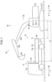
FIG. 1 is a diagram of astop instruction system 30 and the like, and is a diagram of acarrier 10 and awork machine 20 as viewed from a side. -
FIG. 2 is a block diagram of thestop instruction system 30 shown inFIG. 1 . -
FIG. 3 is a flowchart showing processing of acontroller 50 shown inFIG. 1 . -
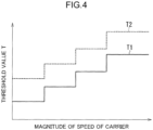
FIG. 4 is a graph showing a relationship between a magnitude of a speed of thecarrier 10 shown inFIG. 1 and a first threshold value T1 and a second threshold value T2 shown inFIG. 3 . -
FIG. 5 is a diagram of thecarrier 10 and thework machine 20 shown inFIG. 1 as viewed from above. -
FIG. 6 is a flowchart showing processing of calculation of the threshold values (S101) shown inFIG. 3 . - A
carrier 10, awork machine 20, and astop instruction system 30 shown inFIG. 1 will be described with reference toFIGS. 1 to 6 . - The
carrier 10 is a vehicle including aplatform 13. Thecarrier 10 is a vehicle that transports a conveyance object loaded by thework machine 20. Thecarrier 10 may be a dump car or a truck. Thecarrier 10 includes acarrier body 11 and theplatform 13. Thecarrier body 11 can travel and supports theplatform 13. Thecarrier body 11 includes acarrier cab 11a. - The
platform 13 accommodates a conveyance object. The conveyance object accommodated in theplatform 13 may be, for example, earth and sand, stones, a waste, or the like. A carrier front rear direction U shown inFIG. 1 is a front rear direction of thecarrier 10. A side facing from theplatform 13 toward thecarrier cab 11a is defined as a carrier front side U1 in the carrier front rear direction U, and a side facing from thecarrier cab 11a toward theplatform 13 is defined as a carrier rear side U2 in the carrier front rear direction U. Theplatform 13 may be movable with respect to thecarrier body 11 or may be fixed to thecarrier body 11. Theplatform 13 includes aplatform floor 13a, a platformrear portion 13b, and aplatform front portion 13d. - The
platform floor 13a is a portion constituting a bottom of theplatform 13. The platformrear portion 13b is a portion (for example, an end) of theplatform 13 on the carrier rear side U2. The platformrear portion 13b protrudes upward from a portion of theplatform floor 13a on the carrier rear side U2 and has, for example, a plate shape (gate board). The platformrear portion 13b has a flat surface or a substantially flat surface extending in a direction orthogonal or substantially orthogonal to the carrier front rear direction U. Theplatform front portion 13d is a portion of theplatform 13 on the carrier front side U1. Theplatform front portion 13d protrudes upward from a portion of theplatform floor 13a on the carrier front side U1 and has, for example, a plate shape (gateway). Theplatform front portion 13d protrudes higher than the platformrear portion 13b. Theplatform front portion 13d has a flat surface or a substantially flat surface extending in a direction orthogonal or substantially orthogonal to the carrier front rear direction U. - The
work machine 20 is a machine that performs work, for example, a construction machine that performs construction work, for example, an excavator. Thework machine 20 captures a conveyance object (for example, excavating earth and sand) and loads the captured conveyance object onto the carrier 10 (for example, removes soil). Thework machine 20 includes alower travelling body 21, anupper slewing body 23, and anattachment 25. - The
lower travelling body 21 causes thework machine 20 to travel. Thelower travelling body 21 includes, for example, left andright crawlers FIG. 5 ). Theupper slewing body 23 is mounted on thelower travelling body 21 so as to be able to slew. - The
attachment 25 is mounted on theupper slewing body 23 so as to be raised and lowered. Theattachment 25 includes aboom 25a, anarm 25b, and adistal end attachment 25c. Theboom 25a is mounted on theupper slewing body 23 so as to be raised and lowered (rotatable up and down). Thearm 25b is rotatably attached to theboom 25a (so as to be pushed and pulled). Thedistal end attachment 25c is provided at a distal end of theattachment 25 and is rotatably attached to thearm 25b. Thedistal end attachment 25c may be a bucket that scoops a conveyance object (for example, earth and sand) or a device (for example, a grapple) that pinches and holds the conveyance obj ect. - A direction in which a rotation axis of slewing of the
upper slewing body 23 with respect to thelower travelling body 21 extends is defined as an up down direction of thework machine 20. A work machine front rear direction X shown inFIG. 1 is a front rear direction of thework machine 20. A side toward which theattachment 25 protrudes from theupper slewing body 23 is defined as a work machine front side X1 in the work machine front rear direction X, the work machine front side X1 being a direction orthogonal to the up down direction of thework machine 20, and the opposite side is defined as a work machine rear side X2 in the work machine front rear direction X. - The
stop instruction system 30 is a system (for example, an automatic horn sounding system) that automatically issues a stop instruction to stop thecarrier 10 approaching thework machine 20. As shown inFIG. 2 , thestop instruction system 30 includes adistance detection unit 41, a carrierspeed detection unit 42, a lower travelling bodyorientation detection unit 43, an attachmentorientation detection unit 44, a stopinstruction output unit 47, and acontroller 50. - The
distance detection unit 41 detects a distance of thecarrier 10 from thework machine 20 shown inFIG. 1 . Thedistance detection unit 41 detects a first distance L1 and a second distance L2. The first distance L1 is a distance (for example, the shortest distance) from aspecific reference position 20a associated with thework machine 20 to the platformrear portion 13b of thecarrier 10. Thereference position 20a is, for example, a position uniquely determined from the position of theupper slewing body 23, and may be, for example, a proximal end of theboom 25a (an end close to the upper slewing body 23), or may be a specific point on a central axis of slewing of theupper slewing body 23 with respect to the lower travellingbody 21. The second distance L2 is a distance (for example, the shortest distance) from thereference position 20a to theplatform front portion 13d. - The distance detection unit 41 (position detection unit) may be able to detect the position of the
carrier 10 relative to thework machine 20. Specifically, thedistance detection unit 41 may detect three-dimensional position information of thecarrier 10 and detect three-dimensional shape information of thecarrier 10. In this case, thedistance detection unit 41 acquires an image (distance image) having distance information (depth information). Thedistance detection unit 41 may detect the position of thecarrier 10 based on three-dimensional information and two-dimensional information (image). - The
distance detection unit 41 may detect the position (three-dimensional position information) of only a part of thecarrier 10, and for example, may detect the position of only theplatform 13 of thecarrier 10. Only onedistance detection unit 41 may be provided, or a plurality ofdistance detection units 41 may be provided. Thedistance detection unit 41 may be mounted on thework machine 20 or may be disposed outside the work machine 20 (for example, at a work site). When thedistance detection unit 41 is disposed outside thework machine 20, it may be possible to detect a position that cannot be detected (for example, a portion hidden by the attachment 25) if thedistance detection unit 41 is mounted only on thework machine 20. When thedistance detection unit 41 is disposed outside thework machine 20, thestop instruction system 30 according to the present embodiment can be applied even if thework machine 20 does not include thedistance detection unit 41. - The
distance detection unit 41 is a sensor capable of detecting a distance in a non-contact manner. Thedistance detection unit 41 may include a device that detects three-dimensional information with laser light, and may include, for example, a light detection and ranging or laser imaging detection and ranging (LiDAR) or a time of flight (TOF) sensor. Thedistance detection unit 41 may include a device (for example, a millimeter-wave radar) that detects three-dimensional information with radio waves. Thedistance detection unit 41 may include a stereo camera. In a case where thedistance detection unit 41 detects the three-dimensional position and shape of thecarrier 10 based on the three-dimensional information and the two-dimensional information, thedistance detection unit 41 may include a camera capable of detecting a two-dimensional image. - The carrier speed detection unit 42 (see
FIG. 2 ) detects a speed of thecarrier 10. The carrierspeed detection unit 42 may be mounted on thework machine 20 or may be disposed outside thework machine 20. The carrierspeed detection unit 42 may be shared or need not be shared with the distance detection unit 41 (the same applies to the lower travelling bodyorientation detection unit 43 and the attachmentorientation detection unit 44 shown inFIG. 2 ). For example, the carrierspeed detection unit 42 may detect (calculate) the speed of thecarrier 10 from a change in the distance per unit time from thework machine 20 to thecarrier 10 shown inFIG. 1 . For example, the carrier speed detection unit 42 (seeFIG. 2 ) may calculate the speed of thecarrier 10 based on three-dimensional position information of thecarrier 10. For example, the carrierspeed detection unit 42 may be a speed sensor provided in thecarrier 10. - The lower travelling body orientation detection unit 43 (see
FIG. 2 ) detects an orientation (for example, an angle) of the lower travellingbody 21 with respect to thecarrier 10. The lower travelling bodyorientation detection unit 43 may be mounted on thework machine 20 or may be disposed outside thework machine 20. For example, the lower travelling body orientation detection unit 43 (seeFIG. 2 ) may calculate an orientation of the lower travellingbody 21 with respect to thecarrier 10 based on an orientation of thecarrier 10 with respect to theupper slewing body 23 and an orientation (slewing angle) of theupper slewing body 23 with respect to the lower travellingbody 21. For example, the lower travelling body orientation detection unit 43 (seeFIG. 2 ) may detect the orientation of the lower travellingbody 21 with respect to thecarrier 10 based on distance images (three-dimensional position and shape information) of thecarrier 10 and the lower travellingbody 21. - The attachment orientation detection unit 44 (see
FIG. 2 ) detects an orientation of theattachment 25. The attachmentorientation detection unit 44 may be mounted on thework machine 20 or may be disposed outside thework machine 20. For example, the attachment orientation detection unit 44 (seeFIG. 2 ) may be one or a plurality of angle sensors mounted on thework machine 20. In this case, the attachment orientation detection unit 44 (seeFIG. 2 ) detects an angle of theboom 25a with respect to theupper slewing body 23, an angle of thearm 25b with respect to theboom 25a, and an angle of thedistal end attachment 25c with respect to thearm 25b. For example, the attachment orientation detection unit 44 (seeFIG. 2 ) may detect the orientation of theattachment 25 based on a distance image of theattachment 25. - The stop instruction output unit 47 (see
FIG. 2 ) outputs a stop instruction. The stopinstruction output unit 47 may be mounted on thework machine 20 or may be disposed outside thework machine 20. The "stop instruction" may be an instruction perceptible by the driver in thecarrier cab 11a of thecarrier 10. In this case, the "stop instruction" may be, for example, an instruction of at least one of sound, light, or vibration. The "stop instruction" may be an electric signal for automatically stopping thecarrier 10. The stopinstruction output unit 47 may be a horn (for example, a horn mounted on the work machine 20), a speaker, a light, or a display (such as a monitor). - The
controller 50 is a computer that inputs and outputs signals, performs arithmetic such as determination and calculation, stores information, and the like. Thecontroller 50 may be mounted on thework machine 20 or may be disposed outside thework machine 20. A threshold value T (first threshold value T1 and second threshold value T2 (seeFIG. 3 )) is set in thecontroller 50. Hereinafter, the first threshold value T1 and the second threshold value T2 will be described mainly with reference toFIG. 3 . - The first threshold value T1 is a threshold value related to the first distance L1 shown in
FIG. 1 . The first threshold value T1 is set so that a predetermined space is provided between the platformrear portion 13b and thework machine 20 when the first distance L1 is equal to the first threshold value T1. The "predetermined space" is a space at which the platformrear portion 13b and thework machine 20 do not come into contact with each other. - The second threshold value T2 is a threshold value related to the second distance L2. The second threshold value T2 is set so that the
attachment 25 can reach theplatform front portion 13d when the second distance L2 is equal to the second threshold value T2. The "can reach" may refer to a state in which theattachment 25 can come into contact with theplatform front portion 13d. The above "can reach" refer to a state in which theattachment 25 can substantially come into contact with theplatform front portion 13d, or may refer to a state in which theattachment 25 can be brought close to theplatform front portion 13d to such an extent that a slight space is formed between theattachment 25 and theplatform front portion 13d. - The outline of the operation of the
stop instruction system 30 and the like is as follows. When at least either a condition α or β described below is satisfied, thecontroller 50 causes the stop instruction output unit 47 (seeFIG. 2 ) to output a stop instruction. The condition α is that the first distance L1 falls from a value greater than the first threshold value T1 to a value equal to or smaller than the first threshold value T1. The condition β is that the second distance L2 falls from a value greater than the second threshold value T2 to a value equal to or smaller than the second threshold value T2. Details of the operation of thestop instruction system 30 and the like will be described with reference to the flowchart shown inFIG. 3 . - In this example, at the start of the processing of the
controller 50 shown inFIG. 3 , thecarrier 10 is sufficiently separated from thework machine 20, the first distance L1 is a value greater than the first threshold value T1, and the second distance L2 is a value greater than the second threshold value T2. In this state, thecarrier 10 moves toward thework machine 20, and the first distance L1 and the second distance L2 gradually decrease. Thecarrier 10 moves toward thework machine 20 in such a direction that the first distance L1 becomes smaller than the second distance L2. That is, thecarrier 10 moves backward toward thework machine 20 as shown inFIG. 1 . For example, thecarrier 10 moves toward thework machine 20 so that the direction of the carrier rear side U2 of thecarrier 10 and the direction of the work machine front side X1 of thework machine 20 are opposite to each other. The work machine front rear direction X and the carrier front rear direction U may be parallel to or inclined with respect to each other. - The
controller 50 calculates the first threshold value T1 and the second threshold value T2 (step S101 shown inFIG. 3 ). This calculation will be described later. The first threshold value T1 and the second threshold value T2 may be predetermined constant values. - The
controller 50 determines whether the first distance L1 detected by thedistance detection unit 41 is equal to or smaller than the first threshold value T1 (whether L1 ≤ T1) (step S11 shown inFIG. 3 ). When L1 ≤ T1 is satisfied, the processing flow proceeds to step S15 (seeFIG. 3 ). When L1 ≤ T1 is not satisfied (when L1 > T1 is satisfied), the processing flow proceeds to step S12 (seeFIG. 3 ). - The
controller 50 determines whether the second distance L2 detected by thedistance detection unit 41 is equal to or smaller than the second threshold value T2 (whether L2 ≤ T2) (step S12 shown inFIG. 3 ). When L2 ≤ T2 is satisfied, the processing flow proceeds to step S15 (seeFIG. 3 ). When L2 ≤ T2 is not satisfied (when L1 > T1 and L2 > T2 are satisfied), the processing flow returns to step S11 (seeFIG. 3 ). - When at least either the condition of L1 ≤ T1 or L2 ≤ T2 is satisfied, the
controller 50 causes the stop instruction output unit 47 (seeFIG. 2 ) to output a stop instruction. Specifically, for example, thecontroller 50 sounds (blows) the horn, which is the stop instruction output unit 47 (seeFIG. 2 ), for a predetermined time. The driver of thecarrier 10 perceives the stop instruction (for example, hears the sound of the horn) and stops thecarrier 10. Alternatively, for example, the stop instruction output unit 47 (seeFIG. 2 ) may stop thecarrier 10 by outputting a signal for automatically stopping thecarrier 10. The contents of the stop instruction output from the stop instruction output unit 47 (seeFIG. 2 ) may be common or different when L1 ≤ T1 is satisfied and when L2 ≤ T2 is satisfied. - The
controller 50 calculates (changes) the threshold value T (the first threshold value T1 and the second threshold value T2) based on various conditions (see step S101 shown inFIG. 3 andFIG. 6 ). - A time lag occurs between the time when the stop instruction output unit 47 (see
FIG. 2 ) outputs the stop instruction (see step S15 shown inFIG. 3 ) and the time when thecarrier 10 actually stops. It is assumed that the higher the speed of thecarrier 10 when the stop instruction is output, the longer the time lag, and thecarrier 10 does not stop at an appropriate position. Therefore, thecontroller 50 changes the threshold value T based on the magnitude of the speed of thecarrier 10 with respect to thework machine 20. That is, thecontroller 50 changes the timing at which the stop instruction is output based on the magnitude of the speed of thecarrier 10 with respect to thework machine 20. The speed of thecarrier 10 with respect to thework machine 20 is detected by the carrier speed detection unit 42 (seeFIG. 2 ). When the speed of thecarrier 10 is higher, thecontroller 50 sets the threshold value T (specifically, each of the first threshold value T1 and the second threshold value T2) to be greater so that the stop instruction is output at an earlier timing (see, for example,FIG. 4 ). Thecontroller 50 may change the threshold value T stepwise as shown inFIG. 4 or continuously with respect to the speed of thecarrier 10. - Depending on the orientation of the
work machine 20, how close thecarrier 10 can approach the work machine 20 (approach thework machine 20 without contacting the work machine) changes. Therefore, thecontroller 50 changes the first threshold value T1 in accordance with the orientation of thework machine 20. - The
controller 50 changes the first threshold value T1 based on information on the size and shape of the lower travellingbody 21 and the orientation (for example, angle) of the lower travellingbody 21 with respect to thecarrier 10. The orientation of the lower travellingbody 21 with respect to thecarrier 10 is detected by the lower travelling body orientation detection unit 43 (seeFIG. 2 ) (details of the detection are as described above). The information (specification information) on the size and shape of the lower travellingbody 21 is set in thecontroller 50. The information on the size and shape of the lower travellingbody 21 may be input to thecontroller 50 by communication, and may be stored in thecontroller 50, for example, at the time of production of thework machine 20. The information on the size and shape of the lower travellingbody 21 may be calculated based on a two-dimensional image or a distance image. In this case, the image and the distance image may be acquired by thedistance detection unit 41, the lower travelling body orientation detection unit 43 (seeFIG. 2 ), or a sensor other than the above. - Specifically, for example, as shown in
FIG. 5 , a straight line passing through thereference position 20a of thework machine 20 and aspecific position 10a (for example, a position closest to thereference position 20a) of thecarrier 10 when viewed from above is defined as a straight line A1. A central axis of the lower travellingbody 21 is defined as a lower travelling bodycentral axis 21a. The lower travelling bodycentral axis 21a is a straight line extending in a direction in which thecrawlers 21c extends, and is a straight line passing through the center of the left andright crawlers central axis 21a, a distance between the lower travellingbody 21 and thecarrier 10 changes, and how close thecarrier 10 can approach the work machine 20 (approach without contacting the work machine 20) changes. For example, the controller 50 (seeFIG. 1 ) sets the first threshold value T1 to be smaller when the angle θ is 0° or 90° than when the angle θ is between 0° and 90° (45° or the like). For example, a length of the lower travellingbody 21 in the front rear direction (a length in the direction in which the lower travelling bodycentral axis 21a extends) may be longer than a length of the lower travellingbody 21 in a width direction (length in direction in which the left andright crawlers FIG. 1 ) sets the first threshold value T1 to be smaller when the angle θ is 90° than when the angle θ is 0°. Note that a method of setting the first threshold value T1 is an example, and the first threshold value T1 can be set variously (the same applies to the following example of the setting method). - The
controller 50 changes the first threshold value T1 based on information on the size and shape of theattachment 25 and the orientation of theattachment 25. The orientation of theattachment 25 is detected by the attachment orientation detection unit 44 (seeFIG. 2 ) (details of the detection are as described above). The information on the size and shape of theattachment 25 is set in thecontroller 50 similarly to the information on the size and shape of the lower travellingbody 21. Thecontroller 50 may further change the first threshold value T1 based on information on the carrier 10 (for example, three-dimensional shape information). The information on thecarrier 10 may be calculated based on a two-dimensional image or a distance image. In this case, the image and the distance image may be acquired by thedistance detection unit 41 or a sensor other than thedistance detection unit 41. - Specifically, for example, the
controller 50 may change the first threshold value T1 based on a height of the attachment 25 (for example, thedistal end attachment 25c) from a ground and a height of theplatform 13 of thecarrier 10 from the ground. For example, when the entiredistal end attachment 25c is located above a predetermined height H (seeFIG. 1 ) determined from the height of theplatform 13, thecontroller 50 sets the first threshold value T1 to be smaller than when at least a part of thedistal end attachment 25c is located below the predetermined height H. For example, thecontroller 50 may compare information on the three-dimensional position and shape of theattachment 25 with information on the three-dimensional position and shape of thecarrier 10, and set the first threshold value T1 so that thecarrier 10 can stop with a predetermined space apart from thework machine 20. - A specific example of processing of calculating the threshold value T by the
controller 50 will be described with reference to a flowchart shown inFIG. 6 . Thecontroller 50 shown inFIG. 1 acquires the magnitude of the speed of thecarrier 10 detected by the carrier speed detection unit 42 (seeFIG. 2 ) (step S201 shown inFIG. 6 ). Thecontroller 50 acquires the orientation of theattachment 25 detected by the attachment orientation detection unit 44 (seeFIG. 2 ) and the orientation of the lower travellingbody 21 detected by the lower travelling body orientation detection unit 43 (seeFIG. 2 ) (step S202 shown inFIG. 6 ). Thecontroller 50 calculates values necessary for calculating the first threshold value T1 and the second threshold value T2 from information acquired in steps S201 and S202 (seeFIG. 6 ). Specifically, for example, thecontroller 50 calculates such a distance (a distance necessary for calculating the first threshold value T1) from thereference position 20a to the platformrear portion 13b that thecarrier 10 can approach thework machine 20 without contacting thework machine 20. In addition, thecontroller 50 calculates such a distance from thereference position 20a to theplatform front portion 13d (a distance necessary for calculating the second threshold value T2) that theattachment 25 reaches theplatform front portion 13d. Then, thecontroller 50 determines (calculates) the first threshold value T1 and the second threshold value T2 from the above values (step S204 shown inFIG. 6 ). - Effects of the
stop instruction system 30 shown inFIG. 1 are as follows. Thestop instruction system 30 issues an instruction to stop thecarrier 10 approaching thework machine 20. Thestop instruction system 30 includes thedistance detection unit 41, the stop instruction output unit 47 (seeFIG. 2 ), and thecontroller 50. Thedistance detection unit 41 detects a distance of thecarrier 10 from thework machine 20. The stop instruction output unit 47 (seeFIG. 2 ) outputs a stop instruction as the instruction to stop thecarrier 10. - [Configuration 1-1] The
distance detection unit 41 detects the first distance L1 and the second distance L2. The first distance L1 is a distance from thespecific reference position 20a associated with thework machine 20 to a portion (the platformrear portion 13b) of theplatform 13 of thecarrier 10 on the carrier rear side U2. - [Configuration 1-2] The second distance L2 is a distance from the
reference position 20a to a portion (theplatform front portion 13d) of theplatform 13 on the carrier front side U1. The first threshold value T1 as a threshold value related to the first distance L1 (seeFIG. 3 ) and the second threshold value T2 as a threshold value related to the second distance L2 (seeFIG. 3 ) are set in thecontroller 50. - [Configuration 1-3] The
controller 50 causes the stop instruction output unit 47 (seeFIG. 2 ) to output a stop instruction at least either when the first distance L1 falls from a value greater than the first threshold value T1 to a value equal to or smaller than the first threshold value T1 or when the second distance L2 falls from a value greater than the second threshold value T2 to a value equal to or smaller than the second threshold value T2. - In [Configuration 1-1] and [Configuration 1-3] described above, the stop instruction output unit 47 (see
FIG. 2 ) outputs the stop instruction when the first distance L1 from thereference position 20a of thework machine 20 to the platformrear portion 13b falls from a value greater than the first threshold value T1 to a value equal to or smaller than the first threshold value T1. Therefore, in a case where the first threshold value T1 is appropriately set, the stop instruction can be issued at a timing when the distance of the platformrear portion 13b from thework machine 20 becomes an appropriate distance. In [Configuration 1-2] and [Configuration 1-3] described above, the stop instruction output unit 47 (seeFIG. 2 ) outputs the stop instruction when the second distance L2 from thereference position 20a of thework machine 20 to theplatform front portion 13d falls from a value greater than the second threshold value T2 to a value equal to or smaller than the second threshold value T2. Therefore, in a case where the second threshold value T2 is appropriately set, the stop instruction can be issued at a timing when the distance of theplatform front portion 13d from thework machine 20 becomes an appropriate distance. Therefore, the stop instruction to stop thecarrier 10 can be issued at a timing when at least either the distance from thework machine 20 to the platformrear portion 13b or the distance from thework machine 20 to theplatform front portion 13d becomes an appropriate distance. As a result, the stop instruction to stop thecarrier 10 can be issued at a timing when the position of thecarrier 10 relative to thework machine 20 becomes appropriate. - [Configuration 2] The first threshold value T1 is set so that a space is provided between a portion (the platform
rear portion 13b) of theplatform 13 on the carrier rear side U2 and thework machine 20 when the first distance L1 is equal to the first threshold value T1. - In [Configuration 2] described above, the stop instruction can be issued at a timing when there is a space between the platform
rear portion 13b and thework machine 20, that is, at a timing when the platformrear portion 13b and thework machine 20 do not come into contact with each other. - [Configuration 3] The second threshold value T2 is set so that a portion (the
platform front portion 13d) of theplatform 13 on the carrier front side U1 can reach theattachment 25 when the second distance L2 is equal to the second threshold value T2. - In [Configuration 3] described above, the stop instruction can be issued at a timing when the
attachment 25 can reach theplatform front portion 13d. - [Configuration 4] The
stop instruction system 30 includes the carrier speed detection unit 42 (seeFIG. 2 ) that detects the speed of thecarrier 10 with respect to thework machine 20. Thecontroller 50 changes the first threshold value T1 and the second threshold value T2 based on the magnitude of the speed detected by the carrier speed detection unit 42 (seeFIG. 4 ). - The following effects can be obtained by [Configuration 4] described above. A time lag occurs between the time when the stop instruction output unit 47 (see
FIG. 2 ) outputs the stop instruction and the time when thecarrier 10 actually stops. This time lag varies depending on the magnitude of the speed of thecarrier 10 when the stop instruction output unit 47 (seeFIG. 2 ) outputs the stop instruction. Therefore, in [Configuration 4], thecontroller 50 changes the first threshold value T1 and the second threshold value T2 based on the magnitude of the speed detected by the carrier speed detection unit 42 (seeFIG. 2 ) (seeFIG. 4 ). Accordingly, the stop instruction can be issued at a more appropriate timing. - [Configuration 5] The
stop instruction system 30 includes the lower travelling body orientation detection unit 43 (seeFIG. 2 ) that detects an orientation of the lower travellingbody 21 of thework machine 20 with respect to thecarrier 10. Thecontroller 50 changes the first threshold value T1 based on the information on the size and shape of the lower travellingbody 21 and the orientation detected by the lower travelling body orientation detection unit 43 (seeFIG. 2 ). - The following effects can be obtained by [Configuration 5] described above. Depending on the size and shape of the lower travelling
body 21 and the orientation (for example, angle) of the lower travellingbody 21 with respect to thecarrier 10, how close thecarrier 10 can approach without contacting thework machine 20 changes (seeFIG. 5 ). Thus, how close thecarrier 10 approaches thework machine 20 when the stop instruction output unit 47 (seeFIG. 2 ) is to output the stop instruction changes. Therefore, in [Configuration 5], thecontroller 50 changes the first threshold value T1 based on the information on the size and shape of the lower travellingbody 21 and the orientation detected by the lower travelling body orientation detection unit 43 (seeFIG. 2 ). Accordingly, the stop instruction can be issued at a more appropriate timing. - [Configuration 6] The
stop instruction system 30 includes the attachment orientation detection unit 44 (seeFIG. 2 ) that detects the orientation of theattachment 25 of thework machine 20. Thecontroller 50 changes the first threshold value T1 based on the information on the size and shape of theattachment 25 and the orientation detected by the attachmentorientation detection unit 44. - The following effects can be obtained by [Configuration 6] described above. Depending on the size and shape of the
attachment 25 and the orientation of theattachment 25, how close thecarrier 10 can approach without contacting thework machine 20 changes. Thus, how close thecarrier 10 approaches thework machine 20 when the stop instruction output unit 47 (seeFIG. 2 ) is to output the stop instruction changes. Therefore, in [Configuration 6], thecontroller 50 changes the first threshold value T1 based on the information on the size and shape of theattachment 25 and the orientation detected by the attachment orientation detection unit 44 (seeFIG. 2 ). Accordingly, the stop instruction can be issued at a more appropriate timing. - The above embodiment may be variously modified. For example, the arrangement, shape, connection, and the like of each component of the embodiment may be changed. For example, the order of the steps in the flowcharts shown in
FIGS. 3 and6 may be changed, and some of the steps need not be performed. For example, the number of components may be changed, and some of the components need not be provided. For example, a plurality of parts different from each other may be described as one part. For example, what has been described as one part may be provided separately in a plurality of different parts. For example, thecontroller 50 shown inFIG. 2 may be one device or a plurality of devices. For example, a threshold value, a range, and the like of the predetermined height H shown inFIG. 1 may be constant, may be changed by manual operation, or may be automatically changed in accordance with some condition.
Claims (6)
- A stop instruction system that issues an instruction to stop a carrier approaching a work machine, the stop instruction system comprising:a distance detection unit that detects a distance of the carrier from the work machine;a stop instruction output unit that outputs a stop instruction as the instruction to stop the carrier; anda controller,wherein the distance detection unit detects a first distance as a distance from a specific reference position associated with the work machine to a portion of a platform of the carrier on a carrier rear side, and a second distance as a distance from the reference position to a portion of the platform on a carrier front side,a first threshold value as a threshold value related to the first distance and a second threshold value as a threshold value related to the second distance are set in the controller, andthe controller causes the stop instruction output unit to output the stop instruction at least either when the first distance falls from a value greater than the first threshold value to a value equal to or smaller than the first threshold value or when the second distance falls from a value greater than the second threshold value to a value equal to or smaller than the second threshold value.
- The stop instruction system according to claim 1, wherein the first threshold value is set so as to provide a space between the portion of the platform on the carrier rear side and the work machine when the first distance is equal to the first threshold value.
- The stop instruction system according to claim 1 or 2, wherein the second threshold value is set so as to enable an attachment of the work machine to reach the portion of the platform on the carrier front side when the second distance is equal to the second threshold value.
- The stop instruction system according to any one of claims 1 to 3, further comprising a carrier speed detection unit that detects a magnitude of a speed of the carrier relative to the work machine,
wherein the controller changes the first threshold value and the second threshold value based on the magnitude of the speed detected by the carrier speed detection unit. - The stop instruction system according to any one of claims 1 to 4, further comprising a lower travelling body orientation detection unit that detects an orientation of a lower travelling body of the work machine with respect to the carrier,
wherein the controller changes the first threshold value based on information on a size and a shape of the lower travelling body and the orientation detected by the lower travelling body orientation detection unit. - The stop instruction system according to any one of claims 1 to 5, further comprising an attachment orientation detection unit that detects an orientation of the attachment of the work machine,
wherein the controller changes the first threshold value based on information on a size and a shape of the attachment and the orientation detected by the attachment orientation detection unit.
Applications Claiming Priority (2)
| Application Number | Priority Date | Filing Date | Title |
|---|---|---|---|
| JP2020161094A JP7354975B2 (en) | 2020-09-25 | 2020-09-25 | Stop instruction system |
| PCT/JP2021/031753 WO2022064968A1 (en) | 2020-09-25 | 2021-08-30 | Stop instruction system |
Publications (3)
| Publication Number | Publication Date |
|---|---|
| EP4194618A1 true EP4194618A1 (en) | 2023-06-14 |
| EP4194618A4 EP4194618A4 (en) | 2024-01-24 |
| EP4194618B1 EP4194618B1 (en) | 2025-10-29 |
Family
ID=80846429
Family Applications (1)
| Application Number | Title | Priority Date | Filing Date |
|---|---|---|---|
| EP21872100.9A Active EP4194618B1 (en) | 2020-09-25 | 2021-08-30 | Stop instruction system |
Country Status (5)
| Country | Link |
|---|---|
| US (1) | US20240026643A1 (en) |
| EP (1) | EP4194618B1 (en) |
| JP (1) | JP7354975B2 (en) |
| CN (1) | CN116324091B (en) |
| WO (1) | WO2022064968A1 (en) |
Family Cites Families (9)
| Publication number | Priority date | Publication date | Assignee | Title |
|---|---|---|---|---|
| JP2922727B2 (en) * | 1992-07-01 | 1999-07-26 | 株式会社フジタ | Travel control system for earth and sand vehicles |
| JPH1088628A (en) * | 1996-09-13 | 1998-04-07 | Hitachi Constr Mach Co Ltd | Wireless alarm device for construction machinery |
| AU2002344089B2 (en) * | 2001-10-18 | 2006-06-22 | Hitachi Construction Machinery Co., Ltd. | Hydraulic shovel work amount detection apparatus, work amount detection method, work amount detection result display apparatus |
| JP6345080B2 (en) * | 2014-10-30 | 2018-06-20 | 日立建機株式会社 | Work machine turning support device |
| CN113107046B (en) * | 2015-12-28 | 2022-09-13 | 住友建机株式会社 | Shovel, shovel system, shovel control device, and shovel control method |
| JP6752168B2 (en) * | 2017-02-27 | 2020-09-09 | 日立建機株式会社 | Dump truck and retreat support device |
| JP7199865B2 (en) * | 2018-07-31 | 2023-01-06 | 株式会社小松製作所 | Systems and methods for controlling work machines |
| JP7156898B2 (en) * | 2018-10-10 | 2022-10-19 | 株式会社小松製作所 | Systems, methods, and work machines including haul vehicles and work machines that load materials onto the haul vehicles |
| CN111399494B (en) * | 2019-01-02 | 2023-07-14 | 长沙智能驾驶研究院有限公司 | An unmanned loading guidance method, device and system |
-
2020
- 2020-09-25 JP JP2020161094A patent/JP7354975B2/en active Active
-
2021
- 2021-08-30 EP EP21872100.9A patent/EP4194618B1/en active Active
- 2021-08-30 CN CN202180063648.1A patent/CN116324091B/en active Active
- 2021-08-30 WO PCT/JP2021/031753 patent/WO2022064968A1/en not_active Ceased
-
2023
- 2023-03-17 US US18/245,728 patent/US20240026643A1/en active Pending
Also Published As
| Publication number | Publication date |
|---|---|
| EP4194618B1 (en) | 2025-10-29 |
| CN116324091A (en) | 2023-06-23 |
| WO2022064968A1 (en) | 2022-03-31 |
| JP7354975B2 (en) | 2023-10-03 |
| US20240026643A1 (en) | 2024-01-25 |
| CN116324091B (en) | 2025-10-28 |
| EP4194618A4 (en) | 2024-01-24 |
| JP2022054096A (en) | 2022-04-06 |
Similar Documents
| Publication | Publication Date | Title |
|---|---|---|
| US10831213B2 (en) | Targeted loading assistance system | |
| US10712451B2 (en) | Anomaly detector for self-location estimation device and vehicle | |
| US9008889B2 (en) | Method of controlling travel within travel system for unmanned vehicle and travel system for unmanned vehicle | |
| EP3919688A1 (en) | Work machinery | |
| JP5997364B2 (en) | Mining machine, mining machine management system, and mining machine management method | |
| CN111095023B (en) | Obstacle detection device | |
| KR102023480B1 (en) | Dump truck | |
| US7966106B2 (en) | Control device and method for guided travel of unmanned vehicle | |
| CN108140306A (en) | Barrier monitoring arrangement, controller of vehicle and Work machine | |
| EP4023823B1 (en) | Device for assessing position of conveyance vehicle | |
| EP3988720A1 (en) | Excavation system, work system, control device, control method, and non-transitory computer readable medium on which program is stored | |
| JP2018142113A (en) | Dump truck and backing assistance apparatus | |
| EP4372155A1 (en) | Work machine | |
| EP3995629A1 (en) | Operation assistance system for work machine | |
| EP4194618B1 (en) | Stop instruction system | |
| US11142187B2 (en) | Parking assistance device | |
| CN112334616A (en) | Asphalt Roller and Asphalt Roller Monitoring System | |
| KR20140095612A (en) | Apparatus for saftely driving construction vehicle and method thereof | |
| US20220356680A1 (en) | Operation area presentation device and operation area presentation method | |
| JP7227871B2 (en) | material handling machine | |
| JP7484623B2 (en) | Stop instruction system | |
| EP4390301A1 (en) | Vehicle determination system | |
| JP2025065872A (en) | Target route setting system, target route setting program, and target route setting method | |
| JP2024064334A (en) | Driving support device, driving support method, and program | |
| EP4219839A1 (en) | Working area setting system and operation target detection system |
Legal Events
| Date | Code | Title | Description |
|---|---|---|---|
| STAA | Information on the status of an ep patent application or granted ep patent |
Free format text: STATUS: THE INTERNATIONAL PUBLICATION HAS BEEN MADE |
|
| PUAI | Public reference made under article 153(3) epc to a published international application that has entered the european phase |
Free format text: ORIGINAL CODE: 0009012 |
|
| STAA | Information on the status of an ep patent application or granted ep patent |
Free format text: STATUS: REQUEST FOR EXAMINATION WAS MADE |
|
| 17P | Request for examination filed |
Effective date: 20230310 |
|
| AK | Designated contracting states |
Kind code of ref document: A1 Designated state(s): AL AT BE BG CH CY CZ DE DK EE ES FI FR GB GR HR HU IE IS IT LI LT LU LV MC MK MT NL NO PL PT RO RS SE SI SK SM TR |
|
| DAV | Request for validation of the european patent (deleted) | ||
| DAX | Request for extension of the european patent (deleted) | ||
| A4 | Supplementary search report drawn up and despatched |
Effective date: 20240103 |
|
| RIC1 | Information provided on ipc code assigned before grant |
Ipc: E02F 9/20 20060101AFI20231220BHEP |
|
| GRAP | Despatch of communication of intention to grant a patent |
Free format text: ORIGINAL CODE: EPIDOSNIGR1 |
|
| STAA | Information on the status of an ep patent application or granted ep patent |
Free format text: STATUS: GRANT OF PATENT IS INTENDED |
|
| INTG | Intention to grant announced |
Effective date: 20250626 |
|
| GRAS | Grant fee paid |
Free format text: ORIGINAL CODE: EPIDOSNIGR3 |
|
| GRAA | (expected) grant |
Free format text: ORIGINAL CODE: 0009210 |
|
| STAA | Information on the status of an ep patent application or granted ep patent |
Free format text: STATUS: THE PATENT HAS BEEN GRANTED |
|
| AK | Designated contracting states |
Kind code of ref document: B1 Designated state(s): AL AT BE BG CH CY CZ DE DK EE ES FI FR GB GR HR HU IE IS IT LI LT LU LV MC MK MT NL NO PL PT RO RS SE SI SK SM TR |
|
| REG | Reference to a national code |
Ref country code: CH Ref legal event code: F10 Free format text: ST27 STATUS EVENT CODE: U-0-0-F10-F00 (AS PROVIDED BY THE NATIONAL OFFICE) Effective date: 20251029 Ref country code: GB Ref legal event code: FG4D |
|
| REG | Reference to a national code |
Ref country code: IE Ref legal event code: FG4D |
|
| REG | Reference to a national code |
Ref country code: DE Ref legal event code: R096 Ref document number: 602021041514 Country of ref document: DE |
|
| REG | Reference to a national code |
Ref country code: NL Ref legal event code: MP Effective date: 20251029 |
|
| PG25 | Lapsed in a contracting state [announced via postgrant information from national office to epo] |
Ref country code: ES Free format text: LAPSE BECAUSE OF FAILURE TO SUBMIT A TRANSLATION OF THE DESCRIPTION OR TO PAY THE FEE WITHIN THE PRESCRIBED TIME-LIMIT Effective date: 20251029 |
|
| REG | Reference to a national code |
Ref country code: LT Ref legal event code: MG9D |
|
| PG25 | Lapsed in a contracting state [announced via postgrant information from national office to epo] |
Ref country code: NO Free format text: LAPSE BECAUSE OF FAILURE TO SUBMIT A TRANSLATION OF THE DESCRIPTION OR TO PAY THE FEE WITHIN THE PRESCRIBED TIME-LIMIT Effective date: 20260129 |
|
| PG25 | Lapsed in a contracting state [announced via postgrant information from national office to epo] |
Ref country code: AT Free format text: LAPSE BECAUSE OF FAILURE TO SUBMIT A TRANSLATION OF THE DESCRIPTION OR TO PAY THE FEE WITHIN THE PRESCRIBED TIME-LIMIT Effective date: 20251029 Ref country code: FI Free format text: LAPSE BECAUSE OF FAILURE TO SUBMIT A TRANSLATION OF THE DESCRIPTION OR TO PAY THE FEE WITHIN THE PRESCRIBED TIME-LIMIT Effective date: 20251029 Ref country code: HR Free format text: LAPSE BECAUSE OF FAILURE TO SUBMIT A TRANSLATION OF THE DESCRIPTION OR TO PAY THE FEE WITHIN THE PRESCRIBED TIME-LIMIT Effective date: 20251029 |
|
| REG | Reference to a national code |
Ref country code: AT Ref legal event code: MK05 Ref document number: 1851691 Country of ref document: AT Kind code of ref document: T Effective date: 20251029 |
|
| PG25 | Lapsed in a contracting state [announced via postgrant information from national office to epo] |
Ref country code: NL Free format text: LAPSE BECAUSE OF FAILURE TO SUBMIT A TRANSLATION OF THE DESCRIPTION OR TO PAY THE FEE WITHIN THE PRESCRIBED TIME-LIMIT Effective date: 20251029 |
|
| PG25 | Lapsed in a contracting state [announced via postgrant information from national office to epo] |
Ref country code: RS Free format text: LAPSE BECAUSE OF FAILURE TO SUBMIT A TRANSLATION OF THE DESCRIPTION OR TO PAY THE FEE WITHIN THE PRESCRIBED TIME-LIMIT Effective date: 20260129 |
|
| PG25 | Lapsed in a contracting state [announced via postgrant information from national office to epo] |
Ref country code: IS Free format text: LAPSE BECAUSE OF FAILURE TO SUBMIT A TRANSLATION OF THE DESCRIPTION OR TO PAY THE FEE WITHIN THE PRESCRIBED TIME-LIMIT Effective date: 20260228 |
|
| PG25 | Lapsed in a contracting state [announced via postgrant information from national office to epo] |
Ref country code: PT Free format text: LAPSE BECAUSE OF FAILURE TO SUBMIT A TRANSLATION OF THE DESCRIPTION OR TO PAY THE FEE WITHIN THE PRESCRIBED TIME-LIMIT Effective date: 20260302 |
|
| PG25 | Lapsed in a contracting state [announced via postgrant information from national office to epo] |
Ref country code: PL Free format text: LAPSE BECAUSE OF FAILURE TO SUBMIT A TRANSLATION OF THE DESCRIPTION OR TO PAY THE FEE WITHIN THE PRESCRIBED TIME-LIMIT Effective date: 20251029 |
|
| PG25 | Lapsed in a contracting state [announced via postgrant information from national office to epo] |
Ref country code: LV Free format text: LAPSE BECAUSE OF FAILURE TO SUBMIT A TRANSLATION OF THE DESCRIPTION OR TO PAY THE FEE WITHIN THE PRESCRIBED TIME-LIMIT Effective date: 20251029 |
|
| PG25 | Lapsed in a contracting state [announced via postgrant information from national office to epo] |
Ref country code: BG Free format text: LAPSE BECAUSE OF FAILURE TO SUBMIT A TRANSLATION OF THE DESCRIPTION OR TO PAY THE FEE WITHIN THE PRESCRIBED TIME-LIMIT Effective date: 20251029 |