US10712451B2 - Anomaly detector for self-location estimation device and vehicle - Google Patents
Anomaly detector for self-location estimation device and vehicle Download PDFInfo
- Publication number
- US10712451B2 US10712451B2 US15/770,363 US201615770363A US10712451B2 US 10712451 B2 US10712451 B2 US 10712451B2 US 201615770363 A US201615770363 A US 201615770363A US 10712451 B2 US10712451 B2 US 10712451B2
- Authority
- US
- United States
- Prior art keywords
- measuring device
- self
- feature point
- coordinates
- shoulder
- Prior art date
- Legal status (The legal status is an assumption and is not a legal conclusion. Google has not performed a legal analysis and makes no representation as to the accuracy of the status listed.)
- Active, expires
Links
- 238000005259 measurement Methods 0.000 claims description 14
- 238000009434 installation Methods 0.000 claims description 9
- 238000001514 detection method Methods 0.000 description 34
- 238000012545 processing Methods 0.000 description 16
- 238000010586 diagram Methods 0.000 description 12
- 238000004891 communication Methods 0.000 description 7
- 238000006243 chemical reaction Methods 0.000 description 6
- 238000000034 method Methods 0.000 description 5
- 238000005286 illumination Methods 0.000 description 4
- 238000005070 sampling Methods 0.000 description 3
- 230000035945 sensitivity Effects 0.000 description 3
- 239000011159 matrix material Substances 0.000 description 2
- 230000005856 abnormality Effects 0.000 description 1
- 238000009412 basement excavation Methods 0.000 description 1
- 238000012937 correction Methods 0.000 description 1
- 230000007423 decrease Effects 0.000 description 1
- 230000006870 function Effects 0.000 description 1
- 238000005065 mining Methods 0.000 description 1
Images


Classifications
-
- G—PHYSICS
- G01—MEASURING; TESTING
- G01S—RADIO DIRECTION-FINDING; RADIO NAVIGATION; DETERMINING DISTANCE OR VELOCITY BY USE OF RADIO WAVES; LOCATING OR PRESENCE-DETECTING BY USE OF THE REFLECTION OR RERADIATION OF RADIO WAVES; ANALOGOUS ARRANGEMENTS USING OTHER WAVES
- G01S19/00—Satellite radio beacon positioning systems; Determining position, velocity or attitude using signals transmitted by such systems
- G01S19/38—Determining a navigation solution using signals transmitted by a satellite radio beacon positioning system
- G01S19/39—Determining a navigation solution using signals transmitted by a satellite radio beacon positioning system the satellite radio beacon positioning system transmitting time-stamped messages, e.g. GPS [Global Positioning System], GLONASS [Global Orbiting Navigation Satellite System] or GALILEO
- G01S19/42—Determining position
- G01S19/48—Determining position by combining or switching between position solutions derived from the satellite radio beacon positioning system and position solutions derived from a further system
-
- G—PHYSICS
- G01—MEASURING; TESTING
- G01S—RADIO DIRECTION-FINDING; RADIO NAVIGATION; DETERMINING DISTANCE OR VELOCITY BY USE OF RADIO WAVES; LOCATING OR PRESENCE-DETECTING BY USE OF THE REFLECTION OR RERADIATION OF RADIO WAVES; ANALOGOUS ARRANGEMENTS USING OTHER WAVES
- G01S17/00—Systems using the reflection or reradiation of electromagnetic waves other than radio waves, e.g. lidar systems
- G01S17/02—Systems using the reflection of electromagnetic waves other than radio waves
- G01S17/06—Systems determining position data of a target
- G01S17/42—Simultaneous measurement of distance and other co-ordinates
-
- G—PHYSICS
- G01—MEASURING; TESTING
- G01S—RADIO DIRECTION-FINDING; RADIO NAVIGATION; DETERMINING DISTANCE OR VELOCITY BY USE OF RADIO WAVES; LOCATING OR PRESENCE-DETECTING BY USE OF THE REFLECTION OR RERADIATION OF RADIO WAVES; ANALOGOUS ARRANGEMENTS USING OTHER WAVES
- G01S17/00—Systems using the reflection or reradiation of electromagnetic waves other than radio waves, e.g. lidar systems
- G01S17/87—Combinations of systems using electromagnetic waves other than radio waves
- G01S17/875—Combinations of systems using electromagnetic waves other than radio waves for determining attitude
-
- G—PHYSICS
- G01—MEASURING; TESTING
- G01S—RADIO DIRECTION-FINDING; RADIO NAVIGATION; DETERMINING DISTANCE OR VELOCITY BY USE OF RADIO WAVES; LOCATING OR PRESENCE-DETECTING BY USE OF THE REFLECTION OR RERADIATION OF RADIO WAVES; ANALOGOUS ARRANGEMENTS USING OTHER WAVES
- G01S17/00—Systems using the reflection or reradiation of electromagnetic waves other than radio waves, e.g. lidar systems
- G01S17/88—Lidar systems specially adapted for specific applications
- G01S17/89—Lidar systems specially adapted for specific applications for mapping or imaging
-
- G—PHYSICS
- G01—MEASURING; TESTING
- G01S—RADIO DIRECTION-FINDING; RADIO NAVIGATION; DETERMINING DISTANCE OR VELOCITY BY USE OF RADIO WAVES; LOCATING OR PRESENCE-DETECTING BY USE OF THE REFLECTION OR RERADIATION OF RADIO WAVES; ANALOGOUS ARRANGEMENTS USING OTHER WAVES
- G01S17/00—Systems using the reflection or reradiation of electromagnetic waves other than radio waves, e.g. lidar systems
- G01S17/88—Lidar systems specially adapted for specific applications
- G01S17/93—Lidar systems specially adapted for specific applications for anti-collision purposes
- G01S17/931—Lidar systems specially adapted for specific applications for anti-collision purposes of land vehicles
-
- G—PHYSICS
- G01—MEASURING; TESTING
- G01S—RADIO DIRECTION-FINDING; RADIO NAVIGATION; DETERMINING DISTANCE OR VELOCITY BY USE OF RADIO WAVES; LOCATING OR PRESENCE-DETECTING BY USE OF THE REFLECTION OR RERADIATION OF RADIO WAVES; ANALOGOUS ARRANGEMENTS USING OTHER WAVES
- G01S19/00—Satellite radio beacon positioning systems; Determining position, velocity or attitude using signals transmitted by such systems
- G01S19/01—Satellite radio beacon positioning systems transmitting time-stamped messages, e.g. GPS [Global Positioning System], GLONASS [Global Orbiting Navigation Satellite System] or GALILEO
- G01S19/13—Receivers
- G01S19/22—Multipath-related issues
-
- G—PHYSICS
- G01—MEASURING; TESTING
- G01S—RADIO DIRECTION-FINDING; RADIO NAVIGATION; DETERMINING DISTANCE OR VELOCITY BY USE OF RADIO WAVES; LOCATING OR PRESENCE-DETECTING BY USE OF THE REFLECTION OR RERADIATION OF RADIO WAVES; ANALOGOUS ARRANGEMENTS USING OTHER WAVES
- G01S19/00—Satellite radio beacon positioning systems; Determining position, velocity or attitude using signals transmitted by such systems
- G01S19/38—Determining a navigation solution using signals transmitted by a satellite radio beacon positioning system
- G01S19/39—Determining a navigation solution using signals transmitted by a satellite radio beacon positioning system the satellite radio beacon positioning system transmitting time-stamped messages, e.g. GPS [Global Positioning System], GLONASS [Global Orbiting Navigation Satellite System] or GALILEO
- G01S19/42—Determining position
- G01S19/48—Determining position by combining or switching between position solutions derived from the satellite radio beacon positioning system and position solutions derived from a further system
- G01S19/485—Determining position by combining or switching between position solutions derived from the satellite radio beacon positioning system and position solutions derived from a further system whereby the further system is an optical system or imaging system
-
- G—PHYSICS
- G01—MEASURING; TESTING
- G01S—RADIO DIRECTION-FINDING; RADIO NAVIGATION; DETERMINING DISTANCE OR VELOCITY BY USE OF RADIO WAVES; LOCATING OR PRESENCE-DETECTING BY USE OF THE REFLECTION OR RERADIATION OF RADIO WAVES; ANALOGOUS ARRANGEMENTS USING OTHER WAVES
- G01S19/00—Satellite radio beacon positioning systems; Determining position, velocity or attitude using signals transmitted by such systems
- G01S19/38—Determining a navigation solution using signals transmitted by a satellite radio beacon positioning system
- G01S19/39—Determining a navigation solution using signals transmitted by a satellite radio beacon positioning system the satellite radio beacon positioning system transmitting time-stamped messages, e.g. GPS [Global Positioning System], GLONASS [Global Orbiting Navigation Satellite System] or GALILEO
- G01S19/42—Determining position
- G01S19/50—Determining position whereby the position solution is constrained to lie upon a particular curve or surface, e.g. for locomotives on railway tracks
-
- G—PHYSICS
- G01—MEASURING; TESTING
- G01S—RADIO DIRECTION-FINDING; RADIO NAVIGATION; DETERMINING DISTANCE OR VELOCITY BY USE OF RADIO WAVES; LOCATING OR PRESENCE-DETECTING BY USE OF THE REFLECTION OR RERADIATION OF RADIO WAVES; ANALOGOUS ARRANGEMENTS USING OTHER WAVES
- G01S7/00—Details of systems according to groups G01S13/00, G01S15/00, G01S17/00
- G01S7/48—Details of systems according to groups G01S13/00, G01S15/00, G01S17/00 of systems according to group G01S17/00
- G01S7/497—Means for monitoring or calibrating
-
- G—PHYSICS
- G05—CONTROLLING; REGULATING
- G05D—SYSTEMS FOR CONTROLLING OR REGULATING NON-ELECTRIC VARIABLES
- G05D1/00—Control of position, course or altitude of land, water, air, or space vehicles, e.g. automatic pilot
- G05D1/02—Control of position or course in two dimensions
-
- G—PHYSICS
- G05—CONTROLLING; REGULATING
- G05D—SYSTEMS FOR CONTROLLING OR REGULATING NON-ELECTRIC VARIABLES
- G05D1/00—Control of position, course or altitude of land, water, air, or space vehicles, e.g. automatic pilot
- G05D1/02—Control of position or course in two dimensions
- G05D1/021—Control of position or course in two dimensions specially adapted to land vehicles
- G05D1/0212—Control of position or course in two dimensions specially adapted to land vehicles with means for defining a desired trajectory
-
- G—PHYSICS
- G01—MEASURING; TESTING
- G01S—RADIO DIRECTION-FINDING; RADIO NAVIGATION; DETERMINING DISTANCE OR VELOCITY BY USE OF RADIO WAVES; LOCATING OR PRESENCE-DETECTING BY USE OF THE REFLECTION OR RERADIATION OF RADIO WAVES; ANALOGOUS ARRANGEMENTS USING OTHER WAVES
- G01S19/00—Satellite radio beacon positioning systems; Determining position, velocity or attitude using signals transmitted by such systems
- G01S19/38—Determining a navigation solution using signals transmitted by a satellite radio beacon positioning system
- G01S19/39—Determining a navigation solution using signals transmitted by a satellite radio beacon positioning system the satellite radio beacon positioning system transmitting time-stamped messages, e.g. GPS [Global Positioning System], GLONASS [Global Orbiting Navigation Satellite System] or GALILEO
- G01S19/42—Determining position
- G01S19/48—Determining position by combining or switching between position solutions derived from the satellite radio beacon positioning system and position solutions derived from a further system
- G01S19/49—Determining position by combining or switching between position solutions derived from the satellite radio beacon positioning system and position solutions derived from a further system whereby the further system is an inertial position system, e.g. loosely-coupled
-
- G—PHYSICS
- G05—CONTROLLING; REGULATING
- G05D—SYSTEMS FOR CONTROLLING OR REGULATING NON-ELECTRIC VARIABLES
- G05D2201/00—Application
- G05D2201/02—Control of position of land vehicles
- G05D2201/021—Mining vehicle
Definitions
- the present invention relates to a technique to detect anomaly in a self-location estimation device installed in a vehicle.
- Patent Literature 1 discloses “A travel controlling apparatus of an unmanned vehicle comprising: a GPS receiver receiving a GPS signal so as to determine a vehicle position; an autonomous navigation computing device to position a position and azimuth of the vehicle on the basis of a traveling direction and a traveling distance of the vehicle; a position measuring portion calculating a present position and azimuth of the vehicle on the basis of the respective measured results of the GPS receiver and the autonomous navigation computing device; and a travel controlling portion controlling the vehicle travel on the basis of the comparison result between a previously set traveling path with the calculated present position and azimuth, wherein a shoulder zone distance measuring device is provided for measuring a distance from the vehicle to a shoulder zone provided in a side of the traveling path, and the position measuring portion compensates at least one of a position positioned by the GPS receiver and
- Patent Literature 1 the terrain information along the traveling path is used to detect anomaly in GPS positioning data. Because of this, the terrain information is required to be beforehand obtained and recorded. Therefore, there is a problem that, in the travelling in an area of which terrain geometries are not known, an anomaly in the GPS positioning data is incapable of being detected in the invention disclosed in Patent Literature 1. In particular, in a mine, the terrain is prone to be varied due to working face, collapse of a mound forming a shoulder, or the like. To address this, in mining dump trucks, a high need exists for a technique to detect anomaly in the self-location estimation processing with a high ability to trace terrain changes.
- the present invention has been made in view of the above problems and it is an object of the present invention to provide a technique to detect anomaly in a self-location estimation device installed in a vehicle without terrain information beforehand obtained.
- a first feature-point coordinate calculation section is provided.
- the first feature-point coordinate calculation section Based on output from a first measuring device that measures a location of its own vehicle relative to each feature point in a feature point group on a surrounding structure around a road surface on which the vehicle travels, the feature point group being lined along a travel direction, the first feature-point coordinate calculation section acquires coordinates of the each feature point expressed in a coordinate system of the first measuring device, and uses the self-location to convert the coordinates into an external coordinate system in order to calculate first coordinates.
- a feature-point trajectory generation section is provided, which generates, based on the first coordinates, a trajectory defined by the external coordinate system of the feature point group.
- a second feature-point coordinate calculation section is provided.
- the second feature-point coordinate calculation section Based on output from a second measuring device that measures a location of its own vehicle relative to a feature point in the feature point group of the surrounding structure, the feature point being located, in the travel direction, rearward of the feature point measured by the first measuring device, at a measurement time of the first measuring device, the second feature-point coordinate calculation section acquires coordinates of the feature point located rearward in the travel direction, the coordinates being expressed in a coordinate system of the second measuring device, and uses the self-location to convert the coordinates into an external coordinate system in order to calculate second coordinates.
- An anomaly determination section determines that anomaly occurs in the self-location estimation device if a deviation between the second coordinates and the trajectory of the feature point group defined by the external coordinate system exceeds a threshold established to deem that the second coordinates are on the trajectory.
- the present invention can provide a technique to detect anomaly in a self-location estimation device installed in a vehicle without terrain information beforehand obtained.
- FIG. 1 is a schematic configuration diagram of an autonomous travel system for working machines used in a mine where a dump truck equipped with an anomaly detector according to the embodiment is operated.
- FIG. 2 is a block diagram illustrating the configuration of a dump truck.
- FIG. 3 shows schematic top views illustrating installation positions of a front lidar 2 a and a rear lidar 2 b, in which (a) illustrates the state of the front lidar 2 a and the rear lidar 2 b both being installed in the front of a dump truck, and (b) illustrates the state of the front lidar 2 a being installed in the front of a dump truck and the rear lidar 2 b being installed at the rear of the dump truck.
- FIG. 4 shows explanatory diagrams illustrating the travel environment of the dump truck and example detection of feature points of a surrounding structure, in which (a) illustrates the travel environment and (b) illustrates example processing to detect a feature point from the output from the front lidar 2 a.
- FIG. 5 is an explanatory diagram of anomaly detection processing of a self-location estimation device.
- FIG. 6 is a flowchart illustrating the flow of operation of the anomaly detector.
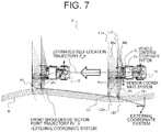
- FIG. 7 is an explanatory diagram illustrating an example calculation of a trajectory of shoulder feature points Pa′.
- FIG. 8 is an explanatory diagram illustrating processing of comparison between a trajectory of shoulder feature points Pa′ and shoulder feature points Pb′.
- FIG. 9 is a perspective schematic view illustrating scanning surfaces of a front lidar 2 a and a rear lidar 2 b according to a second embodiment.
- FIG. 10 is a schematic top view illustrating the scanning surfaces of the front lidar 2 a and the rear lidar 2 b according to the second embodiment.
- FIG. 1 is a schematic configuration diagram of an autonomous travel system for working machines for a mine where a dump truck equipped with an anomaly detector according to the embodiments is operated.
- An autonomous travel system 1 illustrated in FIG. 1 is configured to include a communication connection over a wireless communication network 4 between a dump truck 10 illustrated as an example of mine working machines autonomously traveling and an operation control server 20 installed in an operation control center either close to or away from a quarry.
- a mine includes: loading sites 61 in which an excavator 30 performs excavation work and then loads excavated earth and ores onto the dump truck 10 ; dumping sites 62 in which the dump truck 10 dumps the burden it has hauled; and haul road 60 connecting the loading sites 61 with the dumping sites 62 .
- the dump truck 10 receives operation control information from the operation control server 20 over the wireless communication network 4 , and autonomously travels at a predetermined traveling speed on the haul road 60 in compliance with the operation control information.
- an anomaly detector according to the present invention is installed in the dump truck 10 and anomaly detection is performed using a shoulder as a structure surrounding the haul road 60
- an example vehicle and an example surrounding structure are not limited to the dump truck and the shoulder.
- the vehicle is any mining-application working machine equipped with a self-location estimation device that estimates a self-location based on an external coordinate system using GPS positioning data or inertial data from an IMU (Inertial Measurement Unit) or the like, a type thereof is not an issue.
- the present invention may be applied to a working machine equipped with a GPS receiver to receive self-location information, such as the excavator 30 , a dozer 71 and a water-sprinkler truck 72 .
- self-location information such as the excavator 30 , a dozer 71 and a water-sprinkler truck 72 .
- working face or steep slope which exist around the loading site 61 may be used as surrounding structures.
- the present invention may be applied to a passenger vehicle traveling on an ordinary road, such as a public roadway, a private road and the like, as well as to a mining-application working machine.
- guardrails along a road and buildings beside a road may be used as surrounding structures.
- the side walls in the tunnel may be used as surrounding structures.
- FIG. 2 is a block diagram illustrating the configuration of the dump truck 10 .
- FIG. 3 shows schematic top views illustrating installation positions of a front lidar 2 a and a rear lidar 2 b, in which (a) illustrates the state of the front lidar 2 a and the rear lidar 2 b both being installed in the front of the dump truck 10 , and (b) illustrates the state of the front lidar 2 a being installed in the front of the dump truck 10 and the rear lidar 2 b being installed at the rear of the dump truck 10 .
- the dump truck 10 includes: a self-location estimation device that estimates a self-location based on an external coordinate system (global coordinate system); a vehicle control device 12 that uses the estimated self-location to output a control instruction to a vehicle drive device for autonomous travel of the dump truck 10 ; and a communication device 13 for communication between the dump truck 10 and the operation control server 20 .
- a self-location estimation device that estimates a self-location based on an external coordinate system (global coordinate system)
- vehicle control device 12 that uses the estimated self-location to output a control instruction to a vehicle drive device for autonomous travel of the dump truck 10
- a communication device 13 for communication between the dump truck 10 and the operation control server 20 .
- the self-location estimation device 11 calculates a self-location in the external coordinate system (global coordinate system) on the basis of GPS positioning data received through a GPS antenna 14 .
- the self-location estimation device 11 performs higher-accuracy self-location estimation processing by means of correction of GPS-derived self-location information by use of three: output from an IMU 15 , output from a steering angle sensor 16 that senses an inclination of a front wheel axle (steering angle), and output from a vehicle speed sensor 17 that senses a vehicle speed based on the rotational speed of wheels (driven wheels) of the dump truck 10 .
- the self-location information is output to the vehicle control device 12 to be used for autonomous travel control, or is output to the communication device 13 to be transmitted to the operation control server 20 . In the operation control server 20 , the received self-location information is used for traffic control processing.
- the dump truck 10 further includes two lidars as sensors that detect a relative position between the dump truck 10 and the surrounding structure along a travel route of the dump truck 10 .
- a front Lidar 2 a (corresponding to a first measuring device) for detection in an area ahead of the dump truck 10 in the travel direction is installed on the front left side.
- An intersection line L 1 a (corresponding to a first road-surface scanning line) is between a road surface A and a straight line connected by measure points on the road surface A at which laser light emitted from the front Lidar 2 a arrives, that is, a scanning surface of the front lidar 2 a.
- a rear lidar 2 b (corresponding to a second measuring device) is installed on the front right side of the dump truck 10 .
- An intersection line L 1 b (corresponding to a second road-surface scanning line) is between the road surface A and a straight line connected by measure points on the road surface A at which laser light emitted from the rear lidar 2 b arrives, that is, a scanning surface of the rear lidar 2 b.
- the front lidar 2 a and the rear lidar 2 b are installed to the dump truck 10 at installation angles and positions such that the intersection lines L 1 a, L 2 b are parallel to each other.
- Each of the front lidar 2 a and the rear lidar 2 b performs scans along the measurement points on the road surface A while the emission direction of the laser light is being changed gradually by a predetermined angle, e.g., 0.25 degrees. So that in the scanning surface of each of the front lidar 2 a and the rear lidar 2 b, a distance to the road surface A at each predetermined angle is measured.
- a predetermined angle e.g. 0.25 degrees. So that in the scanning surface of each of the front lidar 2 a and the rear lidar 2 b, a distance to the road surface A at each predetermined angle is measured.
- Each of the front lidar 2 a and the rear lidar 2 b has, for example, 0.25 degree resolution, and resolution between measurement points at a point 30 m away is one meter.
- the front lidar 2 a may be installed on the front of the dump truck 10
- the rear lidar 2 b may be installed at the rear of the dump truck 10
- the front lidar 2 a may be mounted at a mounting angle to the dump truck 10 such that the scanning surface of the front lidar 2 a faces forward
- the rear lidar 2 b may be mounted at a mounting angle to the dump truck 10 such that the scanning surface of the rear lidar 2 b faces rearward.
- the installation positions of the front lidar 2 a and the rear lidar 2 b have only to be determined so that the scanning surfaces of the two lidars are at a distance from each other in the front-rear direction of the travel direction of the dump truck 10 , and the installation positions are not limited to the examples in FIG. 3 .
- the vehicle control device 12 outputs a control instruction signal to the vehicle drive device including, for example, a braking device, a drive torque limiter for limiting a rotation torque instruction value for the drive wheels, and a steering control device that changes the steering angle of the dump truck 10 (all of which are not shown).
- the dump truck 10 further includes an anomaly detector 18 that detects whether or not anomaly occurs in a self-location calculated using the outputs from the front lidar 2 a and the rear lidar 2 b by the self-location estimation device 11 .
- the anomaly detector 18 is configured in collaboration between hardware and software, in which the hardware includes: a computing and control device such as a CPU (Central Processing Unit) or the like; a storage device such as HDD (Hard Disk Drive) and ROM (Read Only Memory) storing a program executed by the anomaly detector 18 , or the like; and RAM (Random Access Memory) serving as a workspace when the CPU executes the program, and the software implements various functions of a first shoulder detection section 181 , a shoulder trajectory generation section 182 , a second shoulder detection section 183 and an anomaly determination section 184 .
- a computing and control device such as a CPU (Central Processing Unit) or the like
- HDD Hard Disk Drive
- ROM Read Only Memory
- RAM Random Access Memory
- portion of the areas of the storage device of the anomaly detector 18 includes: a first shoulder memory section 185 storing shoulder point information defined by the external coordinate system detected by the first shoulder detection section 181 ; and a shoulder trajectory memory section 186 storing shoulder trajectory information generated by the shoulder trajectory generation section 182 .
- the processing executed by each of the first shoulder detection section 181 , the shoulder trajectory generation section 182 , the second shoulder detection section 183 and the anomaly determination section 184 will described later in detail.
- FIG. 4 is an explanatory diagram illustrating the travel environment of the dump truck 10 and example detection of feature points of the surrounding structure, in which (a) illustrates the travel environment and (b) illustrates example processing to detect a feature point from the output from the front lidar 2 a.
- the dump truck 10 operates autonomously to travel on the road surface A such as of a pre-established travel route in a mine or the like.
- a shoulder B is constructed on a side portion of the road surface A of the mine to extend along the road surface A.
- the shoulder B is constructed at least on the side in the close vicinity of the dump truck 10 traveling along, e.g., on the left side in the travel direction, and the shoulder B is a mound having structure with a predetermined height dimension and a predetermined width dimension, which is located at a distance of, e.g., about 30 m from the travel position of the dump truck 10 .
- the shoulder B is used as a surrounding structure located on the periphery of the travel route of the dump truck 10 . And, of the shoulder B, a junction between the road surface A and the shoulder B is used as a feature point P of the surrounding structure.
- the first shoulder detection section 181 calculates the first road-surface scanning line L 1 a and a first shoulder scanning line L 2 a which consists of a line connecting points of reflection from an inclined surface of the shoulder B facing the dump truck 10 , i.e., an intersection line between a scanning surface 40 a and the inclined surface.
- the first shoulder detection section 181 further detects an intersection point between the first road-surface scanning line L 1 a and the first shoulder scanning line L 2 a as a shoulder feature point Pa consisting of the junction between the road surface A and the shoulder B (see FIG. 4( b ) ). It is noted that the shoulder feature point Pa referred to here is defined by a sensor coordinate system giving a relative position of the front lidar 2 a.
- the second shoulder detection section 183 performs processing similar to the foregoing on the basis of the output from the rear lidar 2 b, and detects a shoulder feature point Pb (see FIG. 7 ) defined by a sensor coordinate system.
- FIG. 5 is an explanatory diagram of the anomaly detection processing of the self-location estimation device 11 .
- the self-location estimation device 11 compares an IMU-derived self-location and the GPS positioning position. Then, if the difference between them is small, the two sets of data are combined together (case 1 ), but if the difference is large, the GPS positioning position is not employed (case 2 ). This removes outlier values of the GPS positioning position unexpectedly produced by the influence of multipath.
- FIG. 6 is a flowchart illustrating the flow of the operation of the anomaly detector 18 .
- the self-location estimation device 11 calculates a self-location based on the GPS positioning data received through the GPS antenna 14 , and then uses the output from the IMU 15 , the steering angle sensor 16 and the vehicle speed sensor 17 to compensate for the self-location, thereby calculating a self-location defined by the external coordinate system (S 01 ).
- the road surface A and the shoulder B are measured by the front lidar 2 a of the dump truck 10 , and the measurement data is output to the first shoulder detection section 181 (S 11 ).
- the first shoulder detection section 181 detects a shoulder feature point Pa on the basis of the measurement data by the front lidar 2 a.
- the first shoulder detection section 181 further detects a distance to the shoulder feature point Pa on the basis of the measurement data by the front lidar 2 a, and uses the self-location (the external coordinate system) based on the GPS positioning data calculated in Step 01 to convert the coordinate values of the shoulder feature point Pa in the sensor coordinate system into the coordinate values in the external coordinate system (corresponding to a shoulder feature point Pa′, first coordinates) according to the following formula (1).
- the first shoulder detection section 181 corresponds to a first feature-point coordinate calculation section.
- the first shoulder detection section 181 stores the coordinates of the shoulder feature point Pa′ in the first shoulder memory section 185 (S 12 ).
- (Coordinates of the shoulder feature point Pa′ in the external coordinate system) (the coordinate conversion matrix from the sensor coordinate system of the front lidar 2 a to the vehicle-centered coordinate system) (a coordinate vector of the shoulder feature point Pa based on the sensor coordinate system of the front lidar 2 a )+(a deviation from the installation position of the front lidar 2 a in the vehicle frame in the vehicle-centered coordinate system to the position of the reference point of the self-location estimation device 11)+(a self-location defined by the external coordinate system calculated by the self-location estimation device 11) (1)
- the vehicle-centered coordinate system a three-axis orthogonal system consisting of a vehicle front-rear axis, a left-right axis in the vehicle width direction perpendicular to the front-rear axis, and a vertical axis perpendicular to the front-rear axis and the left-right axis in the right-hand coordinate system, and
- the sensor coordinate system of the front lidar 2 a an xa axis as a radar illumination angle, a ya axis orthogonal to the xa axis on a radar scanning surface, and a za axis perpendicular to the xa axis and the ya axis in the right-hand coordinate system.
- the shoulder trajectory generation section 182 reads the shoulder feature points Pa′ stored in the first shoulder memory section 185 , and arranges the shoulder feature points Pa′ in a time sequence of measurements of the first coordinates of the shoulder feature points Pa′ to generate a trajectory of the first coordinates, and the shoulder trajectory generation section 182 stores the trajectory in the shoulder trajectory memory section (S 13 ).
- the trajectory represents a point sequence of the shoulder feature points Pa′ defined by the external coordinate system.
- the coordinates of the shoulder feature points Pa′ are coordinates of points detected at time intervals corresponding to at least the GPS sampling rate or higher. Accordingly, the shoulder trajectory generation section 182 reads a point group of the shoulder feature points Pa′ in a time sequence, and performs, for example, spline interpolations between the points to obtain a trajectory of the shoulder feature points Pa′ defined by the absolute coordinate system.
- FIG. 7 is an explanatory diagram illustrating an example calculation of a trajectory of the shoulder feature points Pa′. While the dump truck 10 is traveling in the travel direction (from right to left in FIG. 7 ), the self-location estimation device 11 is operated to estimate self-locations. A trajectory of the self-locations is indicated with reference sign Z_tr. Because the shoulder feature point Pa′ results from the addition of the above self-location to the absolute positions of the dump truck 10 and the shoulder feature point Pa, the shape of the trajectory Pa′_tr of the shoulder feature points Pa′ and the shape of reference sign Z_tr indicating the trajectory of the self-locations are similar to each other.
- the rear lidar 2 b measures the road surface and the shoulder in parallel with Step 11 to Step 13 (S 21 ).
- the second shoulder detection section 183 detects a shoulder feature point Pb on the basis of the measurement data by the rear lidar 2 b, and then uses the self-location (the external coordinate system) based on the GPS positioning data calculated in Step 01 to calculate a location of the shoulder feature point Pb in the external coordinate system according to the following formula (1) (S 22 ).
- the second shoulder detection section 183 converts the coordinates of the shoulder feature point Pb which is measured by the rear lidar 2 b and defined by the sensor coordinate system of the rear lidar 2 b, into the absolute coordinate system in order to calculate a shoulder feature point Pb′ (second coordinates). Because of this, the second shoulder detection section 183 corresponds to a second feature-point coordinate calculation section.
- the shoulder feature point Pb′ is also converted into the absolute coordinate system by use of the self-location. Because of this, if the self-location is normally estimated, the shoulder feature point Pb′ should be located on the trajectory Pa′_tr of the shoulder feature point Pa′. Accordingly, this is verified in the next Step.
- the anomaly determination section 184 performs a comparison between the trajectory Pa′_tr of the shoulder feature point Pa′ and the shoulder feature point Pb′, and then if it is determined that a deviation D between them (see FIG. 8 ) exceeds a threshold D th (S 31 /Yes), the anomaly determination section 184 determines that anomaly has occurred in the self-location estimation device 11 , and outputs a stop control instruction signal to the vehicle control device 12 to cause the vehicle control device 12 to operate stopping the dump truck 10 (S 32 ).
- the threshold D th is a threshold defined by the amount of offset of coordinates or distance for determination that the shoulder feature point Pb′ is on the trajectory Pa′_tr of the shoulder feature points Pa′.
- the vehicle control device 12 controls the braking device and the drive torque limiter, which are not shown, to stop the dump truck 10 .
- Conceivable factors in anomaly in the self-location estimation device 11 are influence of multipath on the GPS positioning data, failure of the IMU 15 , the steering angle sensor 16 or the vehicle speed sensor 17 , and the like.
- the anomaly determination section 184 determines that the deviation between the trajectory of the shoulder feature points Pa and the shoulder feature point Pb is equal to or below the threshold D th (S 31 /No), the anomaly determination section 184 determines that the self-location estimation device 11 operates normally, and returns to Step S 01 .
- FIG. 8 is an explanatory diagram illustrating the processing of comparison between the trajectory Pa′_tr of the shoulder feature points Pa′ and the shoulder feature point Pb′.
- the second shoulder detection section 183 uses the self-location including the offset from the true value at time t n-1 to calculate a rear shoulder feature point Pb′. That is, in the last term of the aforementioned formula (2), the self-location including the offset from the true value is used for conversion from the sensor coordinate system to the absolute coordinate system.
- a feature point of a surrounding structure is detected by the front lidar and feature-point coordinates defined by the sensor coordinate system are calculated. Then, the coordinate conversion into the absolute coordinate system is performed on the feature-point coordinates by use of the self-location calculated with the absolute coordinate system, and thereby a trajectory is generated. Then, the trajectory is used as a teaching coordinate series to be compared with the feature-point coordinates detected by the rear lidar. As a result, if the deviation is large (as long as the deviation is inappropriate for being deemed to be correct), it is revealed that anomaly (offset from the true value) occurs in the self-location which has been used in the conversion of the feature point detected by the rear lidar into the absolute coordinate system.
- the measure points of the front lidar obtained during traveling can be used to detect occurrence of anomaly in the self-location estimation device. That is, according to the present embodiment, because the coordinates of a feature point calculated at a certain time point using Formula (2) are compared with the coordinates (properly speaking, the trajectory) of the feature points calculated at a slightly earlier time point using Formula (1), this follows that the comparison is performed at a time point slightly before the error becomes embedded in the GPS positioning data, which in turn enables the determination of the presence or absence of an error even in the above-described case 3 in FIG. 5 .
- FIG. 9 is a perspective schematic view illustrating the scanning surfaces of both of a front lidar 2 a and a rear lidar 2 b according to a second embodiment.
- FIG. 10 is a schematic top view illustrating the scanning surfaces of both of the front lidar 2 a and the rear lidar 2 b according to the second embodiment.
- the front and rear lidars 2 a, 2 b are placed in the dump truck 10 such that the first road-surface scanning line L 1 a of the front lidar 2 a and the second road-surface scanning line L 1 b of the rear lidar 2 b are parallel to each other.
- the front lidar 2 a and the rear lidar 2 b are installed to the dump truck 10 such that the first road-surface scanning line L 1 a and the second road-surface scanning line L 1 b cross each other in front of the vehicle and also within vehicle-width limits.
- portions the same as, similar to or corresponding to those in the first embodiment are indicated by the same reference signs.
- the first road-surface scanning line L 1 a and the second road-surface scanning line L 1 b are provided to cross each other at a cross point G in front of the vehicle.
- the distance Ds between the dump truck 10 and the shoulder B increases, the distance W between the shoulder feature point Pa and the shoulder feature point Pb increases.
- the travel speed is set to be lower if required to travel on a narrow road in proximity to a shoulder provided for protection from slipping down a steep slope. Meanwhile, the travel speed is set to be higher if it is possible to travel at a distance from a shoulder on a wide road.
- the higher the vehicle speed the shorter the time intervals at which the front lidar 2 a and the rear lidar 2 b measure the shoulder. Because of this, effects similar to those when the threshold value D th is set to be relatively high are produced. As a result, as the travel speed increases, the anomaly detection sensitivity of the self-location estimation device 11 decreases. Conversely, at low travel speeds, the anomaly detection sensitivity of the self-location estimation device 11 becomes excessively high, so that there is a possibility of making more often than necessary a determination of occurrence of anomaly.
- the distance W between the shoulder feature point Pa and the shoulder feature point Pb increases. This makes it possible to prevent a reduction in the anomaly detection sensitivity of the self-location estimation device 11 at high travel speeds.
- the cross point G is controlled to be located closer to the dump truck 10 at low travel speeds, and, the laser illumination angle of each lidar with respect to the road surface is controlled to be smaller as the travel speed is higher so that the cross point G is located farther from the dump truck 10 .
- the anomaly detection of the self-location estimation device 11 is able to be performed at regular time intervals.
- Step S 32 instead of or along with the vehicle stop control, the anomaly detection result of the self-location estimation device 11 may be transmitted via the communication device 13 to the operation control server 20 .
- the operation control server 20 may retain the history of receiving the anomaly detection results in memory. Then, if an anomaly detection result has been received from another dump truck 10 in the same or nearby section on the haul road 60 , it can be estimated that the occurrence of anomaly is caused by multipath of the GPS positioning data, rather than the self-location estimation device 11 of each dump truck 10 and the sensors installed in the vehicle.
- using the GPS-derived self-location as an outlier value in the section in question and performing self-location estimation with the output value of the IMU enables avoidance of the control of stopping the dump truck 10 from the subsequent times.
- the front lidar 2 a and the rear lidar 2 b are a plurality of separately structured sensors, but the first measuring device for measuring the shoulder and the second measuring device for measuring the same place following the first measuring device may be configured as a single sensor using a multilayer laser scanner, a stereo camera, or the like.
Abstract
Description
- PATENT LITERATURE 1: Excerpts from specification of U.S. Pat. No. 6,751,535
(Coordinates of the shoulder feature point Pa′ in the external coordinate system)=(the coordinate conversion matrix from the sensor coordinate system of the
Where
(Location of the shoulder B in the external coordinate system)=(a measurement result based on the sensor coordinate system of the
Where the sensor coordinate system of the
- 1 . . . Autonomous travel system
- 2 a . . . Front lidar
- 2 b . . . Rear lidar
- 10 . . . Dump truck
- 11 . . . Self-location estimation device
- 18 . . . Anomaly detector
Claims (7)
Applications Claiming Priority (3)
| Application Number | Priority Date | Filing Date | Title |
|---|---|---|---|
| JP2015-226659 | 2015-11-19 | ||
| JP2015226659A JP6671152B2 (en) | 2015-11-19 | 2015-11-19 | Abnormality detection device of self-position estimation device and vehicle |
| PCT/JP2016/076353 WO2017085989A1 (en) | 2015-11-19 | 2016-09-07 | Device for sensing faults in localization device, and vehicle |
Publications (2)
| Publication Number | Publication Date |
|---|---|
| US20180284292A1 US20180284292A1 (en) | 2018-10-04 |
| US10712451B2 true US10712451B2 (en) | 2020-07-14 |
Family
ID=58718575
Family Applications (1)
| Application Number | Title | Priority Date | Filing Date |
|---|---|---|---|
| US15/770,363 Active 2037-06-05 US10712451B2 (en) | 2015-11-19 | 2016-09-07 | Anomaly detector for self-location estimation device and vehicle |
Country Status (5)
| Country | Link |
|---|---|
| US (1) | US10712451B2 (en) |
| EP (1) | EP3379363B1 (en) |
| JP (1) | JP6671152B2 (en) |
| CN (1) | CN108139755B (en) |
| WO (1) | WO2017085989A1 (en) |
Families Citing this family (12)
| Publication number | Priority date | Publication date | Assignee | Title |
|---|---|---|---|---|
| JP6904208B2 (en) * | 2017-10-10 | 2021-07-14 | トヨタ自動車株式会社 | Axis misalignment judgment device |
| US11022971B2 (en) * | 2018-01-16 | 2021-06-01 | Nio Usa, Inc. | Event data recordation to identify and resolve anomalies associated with control of driverless vehicles |
| JP2019145039A (en) * | 2018-02-23 | 2019-08-29 | Cyberdyne株式会社 | Self-traveling robot and self-traveling robot control method |
| CN108957475A (en) | 2018-06-26 | 2018-12-07 | 东软集团股份有限公司 | A kind of Method for Road Boundary Detection and device |
| JP7132037B2 (en) * | 2018-08-29 | 2022-09-06 | フォルシアクラリオン・エレクトロニクス株式会社 | In-vehicle processing equipment |
| JP7123167B2 (en) * | 2018-12-12 | 2022-08-22 | 日立Astemo株式会社 | External recognition device |
| KR102504229B1 (en) * | 2018-12-18 | 2023-02-28 | 현대자동차주식회사 | Driving control system and method of autonomous traveling vehicle |
| TWI689432B (en) * | 2018-12-26 | 2020-04-01 | 財團法人工業技術研究院 | Automatic vehicular sensor adjustment method and system thereof |
| CN111760795B (en) * | 2019-07-16 | 2022-02-01 | 北京京东乾石科技有限公司 | Method and device for sorting goods |
| CN111505655B (en) * | 2020-04-30 | 2023-09-29 | 中国矿业大学 | Heading machine positioning method based on laser radar |
| CN112230253B (en) * | 2020-10-13 | 2021-07-09 | 电子科技大学 | Track characteristic anomaly detection method based on public slice subsequence |
| CN112415536B (en) * | 2020-11-11 | 2023-07-14 | 南京市测绘勘察研究院股份有限公司 | Method for automatically acquiring abnormal region of vehicle-mounted laser point cloud driving track |
Citations (10)
| Publication number | Priority date | Publication date | Assignee | Title |
|---|---|---|---|---|
| JPH11258339A (en) | 1997-12-16 | 1999-09-24 | Caterpillar Inc | Method and device for detecting obstacle using plural sensors for selective distance detection |
| JP2000172337A (en) | 1998-12-07 | 2000-06-23 | Mitsubishi Electric Corp | Autonomous mobile robot |
| US6751535B2 (en) | 2001-01-22 | 2004-06-15 | Komatsu Ltd. | Travel controlling apparatus of unmanned vehicle |
| JP2015075826A (en) | 2013-10-07 | 2015-04-20 | 日立建機株式会社 | Off-road dump truck |
| US20150125040A1 (en) * | 2013-11-01 | 2015-05-07 | Fujitsu Limited | Travel amount estimation device and travel amount estimating method |
| US9372253B2 (en) * | 2014-01-31 | 2016-06-21 | Denso Corporation | Wireless positioning apparatus |
| US20160373473A1 (en) * | 2015-06-17 | 2016-12-22 | Uber Technologies, Inc. | Trip anomaly detection system |
| US20170124405A1 (en) * | 2011-04-25 | 2017-05-04 | Magna Electronics Inc. | Image processing method for detecting objects using relative motion |
| US20170336515A1 (en) * | 2016-05-23 | 2017-11-23 | Honda Motor Co.,Ltd. | Vehicle position determination device, vehicle control system, vehicle position determination method, and vehicle position determination program product |
| US20180024562A1 (en) * | 2016-07-21 | 2018-01-25 | Mobileye Vision Technologies Ltd. | Localizing vehicle navigation using lane measurements |
Family Cites Families (6)
| Publication number | Priority date | Publication date | Assignee | Title |
|---|---|---|---|---|
| JPH0815414A (en) * | 1994-07-05 | 1996-01-19 | Mitsubishi Electric Corp | Optical radar equipment for vehicle |
| CN202033028U (en) * | 2011-01-25 | 2011-11-09 | 吴立新 | Three-dimensional in-vehicle mining subsidence dynamic monitoring system |
| CN105556338B (en) * | 2013-09-20 | 2022-01-07 | 卡特彼勒公司 | Positioning system using radio frequency signals |
| CN103900497B (en) * | 2014-03-06 | 2016-06-15 | 西南交通大学 | Based on the contactless digger operating device attitude measurement method of vision measurement |
| JP6374695B2 (en) * | 2014-04-28 | 2018-08-15 | 日立建機株式会社 | Road shoulder detection system and mine transport vehicle |
| CA2898288C (en) * | 2014-12-26 | 2017-12-05 | Komatsu Ltd. | Mining machine, management system of mining machine, and management method of mining machine |
-
2015
- 2015-11-19 JP JP2015226659A patent/JP6671152B2/en active Active
-
2016
- 2016-09-07 CN CN201680059522.6A patent/CN108139755B/en active Active
- 2016-09-07 US US15/770,363 patent/US10712451B2/en active Active
- 2016-09-07 EP EP16865992.8A patent/EP3379363B1/en active Active
- 2016-09-07 WO PCT/JP2016/076353 patent/WO2017085989A1/en active Application Filing
Patent Citations (10)
| Publication number | Priority date | Publication date | Assignee | Title |
|---|---|---|---|---|
| JPH11258339A (en) | 1997-12-16 | 1999-09-24 | Caterpillar Inc | Method and device for detecting obstacle using plural sensors for selective distance detection |
| JP2000172337A (en) | 1998-12-07 | 2000-06-23 | Mitsubishi Electric Corp | Autonomous mobile robot |
| US6751535B2 (en) | 2001-01-22 | 2004-06-15 | Komatsu Ltd. | Travel controlling apparatus of unmanned vehicle |
| US20170124405A1 (en) * | 2011-04-25 | 2017-05-04 | Magna Electronics Inc. | Image processing method for detecting objects using relative motion |
| JP2015075826A (en) | 2013-10-07 | 2015-04-20 | 日立建機株式会社 | Off-road dump truck |
| US20150125040A1 (en) * | 2013-11-01 | 2015-05-07 | Fujitsu Limited | Travel amount estimation device and travel amount estimating method |
| US9372253B2 (en) * | 2014-01-31 | 2016-06-21 | Denso Corporation | Wireless positioning apparatus |
| US20160373473A1 (en) * | 2015-06-17 | 2016-12-22 | Uber Technologies, Inc. | Trip anomaly detection system |
| US20170336515A1 (en) * | 2016-05-23 | 2017-11-23 | Honda Motor Co.,Ltd. | Vehicle position determination device, vehicle control system, vehicle position determination method, and vehicle position determination program product |
| US20180024562A1 (en) * | 2016-07-21 | 2018-01-25 | Mobileye Vision Technologies Ltd. | Localizing vehicle navigation using lane measurements |
Non-Patent Citations (1)
| Title |
|---|
| International Search Report of PCT/JP2016/076353 dated Nov. 8, 2016. |
Also Published As
| Publication number | Publication date |
|---|---|
| CN108139755A (en) | 2018-06-08 |
| WO2017085989A1 (en) | 2017-05-26 |
| JP2017097479A (en) | 2017-06-01 |
| EP3379363A4 (en) | 2019-09-04 |
| US20180284292A1 (en) | 2018-10-04 |
| CN108139755B (en) | 2021-02-12 |
| EP3379363A1 (en) | 2018-09-26 |
| EP3379363B1 (en) | 2023-07-05 |
| JP6671152B2 (en) | 2020-03-25 |
Similar Documents
| Publication | Publication Date | Title |
|---|---|---|
| US10712451B2 (en) | Anomaly detector for self-location estimation device and vehicle | |
| AU2014374841B2 (en) | Mining machine, management system of mining machine, and management method of mining machine | |
| JP6909726B2 (en) | Work machine control system, work machine, work machine management system, and work machine management method | |
| US9008889B2 (en) | Method of controlling travel within travel system for unmanned vehicle and travel system for unmanned vehicle | |
| EP3139361B1 (en) | Road-shoulder-detecting system and transportation vehicle for mining | |
| US9234758B2 (en) | Machine positioning system utilizing position error checking | |
| WO2017119517A1 (en) | Working-machine control system, working machine, and working-machine control method | |
| US10146228B2 (en) | Work vehicle control system | |
| WO2016121688A1 (en) | Obstacle detection device for transport vehicle | |
| JP6757749B2 (en) | Work machine management system, work machine, work machine management method | |
| JP6672339B2 (en) | Work machine management system and work machine | |
| JP2015125760A (en) | Mine work machine | |
| JP7199984B2 (en) | WORK VEHICLE CONTROL SYSTEM AND WORK VEHICLE CONTROL METHOD | |
| US11835643B2 (en) | Work machine control system, work machine, and work machine control method | |
| JP6909752B2 (en) | Work machine retreat support device | |
| US11059480B2 (en) | Collision avoidance system with elevation compensation | |
| WO2020122212A1 (en) | Transport vehicle management system and transport vehicle management method | |
| AU2019313721B2 (en) | Work machine control system, work machine, and work machine control method | |
| AU2014271294B2 (en) | Machine positioning system utilizing relative pose information | |
| US9200904B2 (en) | Traffic analysis system utilizing position based awareness | |
| JP6387135B2 (en) | Road shoulder detection system and mine transport vehicle | |
| JP6293328B2 (en) | Road shoulder detection system and mine transport vehicle | |
| WO2021052598A1 (en) | A navigation system for a vehicle arranged at a working space and a method of navigating a vehicle arranged at a working space |
Legal Events
| Date | Code | Title | Description |
|---|---|---|---|
| AS | Assignment |
Owner name: HITACHI CONSTRUCTION MACHINERY CO., LTD., JAPAN Free format text: ASSIGNMENT OF ASSIGNORS INTEREST;ASSIGNORS:ONO, YUKIHIKO;ISHIMOTO, HIDEFUMI;TANAKA, WATARU;SIGNING DATES FROM 20180330 TO 20180405;REEL/FRAME:045611/0048 |
|
| FEPP | Fee payment procedure |
Free format text: ENTITY STATUS SET TO UNDISCOUNTED (ORIGINAL EVENT CODE: BIG.); ENTITY STATUS OF PATENT OWNER: LARGE ENTITY |
|
| STPP | Information on status: patent application and granting procedure in general |
Free format text: DOCKETED NEW CASE - READY FOR EXAMINATION |
|
| STPP | Information on status: patent application and granting procedure in general |
Free format text: NOTICE OF ALLOWANCE MAILED -- APPLICATION RECEIVED IN OFFICE OF PUBLICATIONS |
|
| STPP | Information on status: patent application and granting procedure in general |
Free format text: PUBLICATIONS -- ISSUE FEE PAYMENT RECEIVED |
|
| STCF | Information on status: patent grant |
Free format text: PATENTED CASE |
|
| MAFP | Maintenance fee payment |
Free format text: PAYMENT OF MAINTENANCE FEE, 4TH YEAR, LARGE ENTITY (ORIGINAL EVENT CODE: M1551); ENTITY STATUS OF PATENT OWNER: LARGE ENTITY Year of fee payment: 4 |