EP4194430A1 - Method for manufacturing hydrocarbon compound from carbon dioxide at concentrations including low concentration range - Google Patents
Method for manufacturing hydrocarbon compound from carbon dioxide at concentrations including low concentration range Download PDFInfo
- Publication number
- EP4194430A1 EP4194430A1 EP21852987.3A EP21852987A EP4194430A1 EP 4194430 A1 EP4194430 A1 EP 4194430A1 EP 21852987 A EP21852987 A EP 21852987A EP 4194430 A1 EP4194430 A1 EP 4194430A1
- Authority
- EP
- European Patent Office
- Prior art keywords
- carbon dioxide
- catalyst
- hydrocarbon compound
- absorption
- gas
- Prior art date
- Legal status (The legal status is an assumption and is not a legal conclusion. Google has not performed a legal analysis and makes no representation as to the accuracy of the status listed.)
- Pending
Links
Images




Classifications
-
- C—CHEMISTRY; METALLURGY
- C07—ORGANIC CHEMISTRY
- C07C—ACYCLIC OR CARBOCYCLIC COMPOUNDS
- C07C1/00—Preparation of hydrocarbons from one or more compounds, none of them being a hydrocarbon
- C07C1/02—Preparation of hydrocarbons from one or more compounds, none of them being a hydrocarbon from oxides of a carbon
- C07C1/12—Preparation of hydrocarbons from one or more compounds, none of them being a hydrocarbon from oxides of a carbon from carbon dioxide with hydrogen
-
- B—PERFORMING OPERATIONS; TRANSPORTING
- B01—PHYSICAL OR CHEMICAL PROCESSES OR APPARATUS IN GENERAL
- B01J—CHEMICAL OR PHYSICAL PROCESSES, e.g. CATALYSIS OR COLLOID CHEMISTRY; THEIR RELEVANT APPARATUS
- B01J21/00—Catalysts comprising the elements, oxides, or hydroxides of magnesium, boron, aluminium, carbon, silicon, titanium, zirconium, or hafnium
- B01J21/02—Boron or aluminium; Oxides or hydroxides thereof
- B01J21/04—Alumina
-
- B—PERFORMING OPERATIONS; TRANSPORTING
- B01—PHYSICAL OR CHEMICAL PROCESSES OR APPARATUS IN GENERAL
- B01J—CHEMICAL OR PHYSICAL PROCESSES, e.g. CATALYSIS OR COLLOID CHEMISTRY; THEIR RELEVANT APPARATUS
- B01J23/00—Catalysts comprising metals or metal oxides or hydroxides, not provided for in group B01J21/00
- B01J23/38—Catalysts comprising metals or metal oxides or hydroxides, not provided for in group B01J21/00 of noble metals
- B01J23/40—Catalysts comprising metals or metal oxides or hydroxides, not provided for in group B01J21/00 of noble metals of the platinum group metals
- B01J23/46—Ruthenium, rhodium, osmium or iridium
- B01J23/462—Ruthenium
-
- B—PERFORMING OPERATIONS; TRANSPORTING
- B01—PHYSICAL OR CHEMICAL PROCESSES OR APPARATUS IN GENERAL
- B01J—CHEMICAL OR PHYSICAL PROCESSES, e.g. CATALYSIS OR COLLOID CHEMISTRY; THEIR RELEVANT APPARATUS
- B01J23/00—Catalysts comprising metals or metal oxides or hydroxides, not provided for in group B01J21/00
- B01J23/38—Catalysts comprising metals or metal oxides or hydroxides, not provided for in group B01J21/00 of noble metals
- B01J23/54—Catalysts comprising metals or metal oxides or hydroxides, not provided for in group B01J21/00 of noble metals combined with metals, oxides or hydroxides provided for in groups B01J23/02 - B01J23/36
- B01J23/56—Platinum group metals
- B01J23/58—Platinum group metals with alkali- or alkaline earth metals
-
- B—PERFORMING OPERATIONS; TRANSPORTING
- B01—PHYSICAL OR CHEMICAL PROCESSES OR APPARATUS IN GENERAL
- B01J—CHEMICAL OR PHYSICAL PROCESSES, e.g. CATALYSIS OR COLLOID CHEMISTRY; THEIR RELEVANT APPARATUS
- B01J23/00—Catalysts comprising metals or metal oxides or hydroxides, not provided for in group B01J21/00
- B01J23/70—Catalysts comprising metals or metal oxides or hydroxides, not provided for in group B01J21/00 of the iron group metals or copper
- B01J23/74—Iron group metals
-
- B—PERFORMING OPERATIONS; TRANSPORTING
- B01—PHYSICAL OR CHEMICAL PROCESSES OR APPARATUS IN GENERAL
- B01J—CHEMICAL OR PHYSICAL PROCESSES, e.g. CATALYSIS OR COLLOID CHEMISTRY; THEIR RELEVANT APPARATUS
- B01J23/00—Catalysts comprising metals or metal oxides or hydroxides, not provided for in group B01J21/00
- B01J23/70—Catalysts comprising metals or metal oxides or hydroxides, not provided for in group B01J21/00 of the iron group metals or copper
- B01J23/76—Catalysts comprising metals or metal oxides or hydroxides, not provided for in group B01J21/00 of the iron group metals or copper combined with metals, oxides or hydroxides provided for in groups B01J23/02 - B01J23/36
- B01J23/78—Catalysts comprising metals or metal oxides or hydroxides, not provided for in group B01J21/00 of the iron group metals or copper combined with metals, oxides or hydroxides provided for in groups B01J23/02 - B01J23/36 with alkali- or alkaline earth metals
-
- C—CHEMISTRY; METALLURGY
- C07—ORGANIC CHEMISTRY
- C07C—ACYCLIC OR CARBOCYCLIC COMPOUNDS
- C07C2523/00—Catalysts comprising metals or metal oxides or hydroxides, not provided for in group C07C2521/00
- C07C2523/38—Catalysts comprising metals or metal oxides or hydroxides, not provided for in group C07C2521/00 of noble metals
- C07C2523/40—Catalysts comprising metals or metal oxides or hydroxides, not provided for in group C07C2521/00 of noble metals of the platinum group metals
- C07C2523/46—Ruthenium, rhodium, osmium or iridium
-
- C—CHEMISTRY; METALLURGY
- C07—ORGANIC CHEMISTRY
- C07C—ACYCLIC OR CARBOCYCLIC COMPOUNDS
- C07C2523/00—Catalysts comprising metals or metal oxides or hydroxides, not provided for in group C07C2521/00
- C07C2523/38—Catalysts comprising metals or metal oxides or hydroxides, not provided for in group C07C2521/00 of noble metals
- C07C2523/54—Catalysts comprising metals or metal oxides or hydroxides, not provided for in group C07C2521/00 of noble metals combined with metals, oxides or hydroxides provided for in groups C07C2523/02 - C07C2523/36
- C07C2523/56—Platinum group metals
- C07C2523/58—Platinum group metals with alkali- or alkaline earth metals or beryllium
-
- C—CHEMISTRY; METALLURGY
- C07—ORGANIC CHEMISTRY
- C07C—ACYCLIC OR CARBOCYCLIC COMPOUNDS
- C07C2523/00—Catalysts comprising metals or metal oxides or hydroxides, not provided for in group C07C2521/00
- C07C2523/70—Catalysts comprising metals or metal oxides or hydroxides, not provided for in group C07C2521/00 of the iron group metals or copper
- C07C2523/74—Iron group metals
-
- C—CHEMISTRY; METALLURGY
- C07—ORGANIC CHEMISTRY
- C07C—ACYCLIC OR CARBOCYCLIC COMPOUNDS
- C07C2523/00—Catalysts comprising metals or metal oxides or hydroxides, not provided for in group C07C2521/00
- C07C2523/70—Catalysts comprising metals or metal oxides or hydroxides, not provided for in group C07C2521/00 of the iron group metals or copper
- C07C2523/74—Iron group metals
- C07C2523/755—Nickel
-
- Y—GENERAL TAGGING OF NEW TECHNOLOGICAL DEVELOPMENTS; GENERAL TAGGING OF CROSS-SECTIONAL TECHNOLOGIES SPANNING OVER SEVERAL SECTIONS OF THE IPC; TECHNICAL SUBJECTS COVERED BY FORMER USPC CROSS-REFERENCE ART COLLECTIONS [XRACs] AND DIGESTS
- Y02—TECHNOLOGIES OR APPLICATIONS FOR MITIGATION OR ADAPTATION AGAINST CLIMATE CHANGE
- Y02C—CAPTURE, STORAGE, SEQUESTRATION OR DISPOSAL OF GREENHOUSE GASES [GHG]
- Y02C20/00—Capture or disposal of greenhouse gases
- Y02C20/40—Capture or disposal of greenhouse gases of CO2
Definitions
- the present invention relates to a method for producing a hydrocarbon compound from carbon dioxide (CO 2 ). More particularly, the present invention relates to a method for producing a hydrocarbon compound from CO 2 at concentrations including a low concentration range.
- Patent Document 1 discloses, as an example of a methanation catalyst that performs CO 2 absorption and conversion, a material in which: a CO 2 capture component selected from the group consisting of an alkali metal compound (Li, Na, K, Rb, Cs or the like) and an alkaline earth metal compound (Mg, Ca, Sr, Ba or the like); a methanation catalyst component selected from the group consisting of Ru, Ni and Co; and Si; are supported on an oxide support (such as an alumina support or a titania support).
- Patent document 1 examines the composition of the catalyst for efficiently carrying out the methanation of CO 2 even in cases where a raw material gas contains O 2 along with CO 2 .
- Non-patent Document 1 discloses Ni/K 2 CO 3 /MgO and Ni/K 2 CO 3 /ZrO 2 , as CO 2 absorption-conversion carrier particles (from 150 to 300 ⁇ m) capable of absorbing and converting CO 2 with a single material.
- Non-patent Document 2 discloses a dual-functional material (DFM) capable of absorbing and converting CO 2 with a single material, and a DFM in which a CO 2 capture component (such as Na 2 O) and a methanation catalyst component (such as Ru) are supported on Al 2 O 3 (alumina) is described therein.
- a CO 2 capture component such as Na 2 O
- a methanation catalyst component such as Ru
- Non-patent Document 3 describes the direct air capture (DAC) of CO 2 contained in the atmosphere. First, K 2 CO 3 /Al 2 O 3 in an absorption vessel is allowed to absorb CO 2 in the atmosphere, and then a high concentration of CO 2 accumulated in the absorption vessel is introduced into another reaction vessel in which an Ru/Al 2 O 3 catalyst is kept, to perform methanation.
- DAC direct air capture
- Patent Document 1 Japanese Patent Application Publication No.2019-188353
- an object of the present invention is to provide a means for directly capturing CO 2 at concentrations including a low concentration range by a catalyst itself, without having to perform a CO 2 separation operation such as amine absorption or membrane separation, and converting the captured CO 2 to a hydrocarbon compound.
- An embodiment of the present invention relates to a method for producing a hydrocarbon compound from carbon dioxide, the method including the steps of:
- the present embodiment provides a means for capturing low-concentration CO 2 from a gas containing carbon dioxide at concentrations including a low concentration range, without having to separate and concentrate the same, and efficiently producing a hydrocarbon compound. That is, the present embodiment can be expected to be used for the removal of carbon dioxide from the atmosphere containing a low concentration of CO 2 , and the like.
- an absorption-conversion catalyst comprising: an oxide support; a first component supported on the oxide support and comprising at least one selected from the group consisting of an alkali metal and an alkaline earth metal; and a second component supported on the oxide support and comprising at least one selected from the group consisting of Ni, Fe, Co, Cu and Ru; is provided.
- absorption-conversion catalyst refers to a catalyst having an ability to absorb carbon dioxide under predetermined conditions and an ability to convert carbon dioxide to a hydrocarbon compound using a reducing gas.
- the above-described absorption-conversion catalyst comprises: an oxide support; a first component supported on the oxide support and comprising at least one selected from the group consisting of an alkali metal compound and an alkaline earth metal compound; and a second component supported on the oxide support and comprising at least one selected from the group consisting of Ni, Fe, Co, Cu and Ru.
- the oxide support in the absorption-conversion catalyst is not particularly limited as long as it is used as a catalyst support. From the viewpoint of its high activity, however, the oxide support is preferably an alumina support, a silica support, a titania support, a zirconia support, a ceria support, a magnesia support or the like, and more preferably an alumina support. These oxide supports may be used singly, or in combination of two or more kinds thereof.
- the absorption-conversion catalyst preferably has, but not particularly limited to, an average particle size (median diameter, D50) of from 0.1 to 500 ⁇ m, more preferably from 1 to 300 ⁇ m, and particularly preferably from 50 to 200 ⁇ m, from the viewpoint of usability.
- the absorption-conversion catalyst preferably has a specific surface area of from 10 to 2,000 m 2 /g, more preferably from 20 to 1,000 m 2 /g, and particularly preferably from 30 to 500 m 2 /g, but not particularly limited thereto, as well.
- the average particle size of the absorption-conversion catalyst can be measured, for example, by the dynamic light scattering method, the small-angle X-ray scattering method, the laser diffraction method or the like.
- the specific surface area of the absorption-conversion catalyst can be measured, for example, by the gas absorption method, the permeation method or the like.
- the first component comprising at least one selected from the group consisting of an alkali metal and an alkaline earth metal, is a carbon dioxide capture component.
- the carbon dioxide capture component is supported on the oxide support.
- the carbon dioxide capture component selectively captures carbon dioxide, and the captured carbon dioxide is allowed to react with a reducing gas in the presence of a catalyst component for converting carbon dioxide to a hydrocarbon (hereinafter, referred to as "hydrocarbonation catalyst component"), to produce a hydrocarbon compound from carbon dioxide.
- hydrocarbonation catalyst component a catalyst component for converting carbon dioxide to a hydrocarbon
- Examples of the carbon dioxide capture component include an alkali metal and an alkaline earth metal.
- Examples of the alkali metal include Li, Na, K, Rb and Cs. Among these, Na and K are preferred, and Na is particularly preferred.
- Examples of the alkaline earth metal include Mg, Ca, Sr and Ba. Among these, Ca is preferred from the viewpoint of durability.
- the carbon dioxide capture performance of the absorption-conversion catalyst is decreased, and fails to efficiently reduce carbon dioxide, thereby resulting in a decrease in the production efficiency of producing a hydrocarbon compound from carbon dioxide.
- the amount of the carbon dioxide capture component to be supported is too large, on the other hand, the coarsening of the carbon dioxide capture component, the pore clogging of the oxide support and the like occur, thereby resulting in a decrease in the carbon dioxide capture performance and the production efficiency of the hydrocarbon compound.
- the amount of the carbon dioxide capture component to be supported is preferably from 0.1 to 40 parts by mass, more preferably from 1 to 30 parts by mass, and particularly preferably from 5 to 20 parts by mass, with respect to 100 parts by mass of the oxide support.
- the second component comprising at least one selected from the group consisting of Ni, Fe, Co, Cu and Ru is a hydrocarbonation catalyst component.
- the hydrocarbonation catalyst component the carbon dioxide captured in the above-described carbon dioxide capture component is allowed to react with a reducing gas, to produce a hydrocarbon compound from carbon dioxide.
- hydrocarbonation catalyst component examples include Ni, Fe, Co, Cu and Ru. Among these, Ni is preferred.
- the amount of the hydrocarbonation catalyst component to be supported is preferably from 0.1 to 40 parts by mass, more preferably from 1 to 30 parts by mass and particularly preferably from 5 to 20 parts by mass, with respect to 100 parts by mass of the oxide support.
- the absorption-conversion catalyst described above can be produced based on a known method for producing an absorption-conversion catalyst.
- the absorption-conversion catalyst can be produced by the method described in the Examples of the present specification.
- the absorption-conversion catalyst is brought into contact with a gas containing carbon dioxide at a pressure higher than an atmospheric pressure, to allow the absorption-conversion catalyst to capture carbon dioxide.
- the carbon dioxide capture performance of the absorption-conversion catalyst and the carbon dioxide hydrocarbonation performance of the absorption-conversion catalyst can be improved, by performing the reactions at a pressure higher than the atmospheric pressure. Therefore, it is possible to perform the conversion to a hydrocarbon compound also from a gas containing a low concentration of carbon dioxide.
- the method for adjusting the pressure of the atmosphere in which the absorption-conversion catalyst is allowed to capture carbon dioxide to a pressure higher than the atmospheric pressure is not particularly limited, as long as such a high pressure can be achieved.
- the method may be one in which a gas containing carbon dioxide, as a raw material, is pressurized and introduced into a reactor, or the like.
- the pressure of the atmosphere in which the absorption-conversion catalyst is allowed to capture carbon dioxide is preferably more than 1 and not more than 9 atm, more preferably from 1.5 to 9 atm, still more preferably from 3 to 9 atm, and particularly preferably from 6 to 9 atm, from the viewpoints of inhibiting the degradation of the catalyst and obtaining a high carbon dioxide capture efficiency.
- the temperature of the atmosphere in which the absorption-conversion catalyst is allowed to capture carbon dioxide can be adjusted as appropriate, depending on the pressure and the like of the atmosphere. However, the temperature is preferably from room temperature to 600°C, from the viewpoints of inhibiting the condensation of moisture to the catalyst and the oxidation of the hydrocarbonation catalyst component.
- the period of time during which the absorption-conversion catalyst is allowed to capture carbon dioxide can be adjusted as appropriate, depending on the pressure, the temperature, the carbon dioxide concentration and the like, of the atmosphere.
- the concentration of carbon dioxide in the gas as the raw material in the production method according to the present embodiment is not particularly limited. As described above, it is possible to perform the conversion to a hydrocarbon compound also from a gas containing a low concentration of carbon dioxide. Specifically, the conversion to a hydrocarbon compound can be performed also from the air, which is a gas that usually contains carbon dioxide at a low concentration of about 300 ppm.
- the concentration of carbon dioxide in the gas as the raw material be, for example, from 0.01 to 5 vol% (from 100 to 50,000 ppm), more preferably from 0.03 to 5 vol% (from 300 to 50,000 ppm), and still more preferably from 0.04 to 3 vol% (from 400 to 30,000 ppm), and yet still more preferably from 0.1 to 1 vol% (from 1,000 to 10,000 ppm).
- the reducing gas is not particularly limited as long as carbon dioxide can be converted to a hydrocarbon compound.
- pure hydrogen gas or a hydrogen-containing gas is preferred. It is also possible to use a hydrogen gas obtained by water electrolysis using an energy-saving power generation system, as the reducing gas.
- Another gas(es) to be contained in the hydrogen-containing gas is/are not particularly limited as long as the reduction reaction of carbon dioxide is not inhibited.
- an inert gas such as a helium gas, a nitrogen gas and/or the like is/are preferred.
- the concentration of hydrogen in the hydrogen-containing gas is preferably 5 vol% or more, and more preferably 10 vol% or more, from the viewpoint of improving the reduction efficiency.
- the absorption-conversion catalyst in which carbon dioxide is captured is brought into contact with a reducing gas at a pressure higher than a atmospheric pressure, to obtain a hydrocarbon compound.
- the method for adjusting the pressure of the atmosphere in which the captured carbon dioxide is allowed to react with a reducing gas to a pressure higher than the atmospheric pressure is not particularly limited as long as such a high can be achieved.
- the method may be one in which a reducing gas is pressurized and introduced into a reactor, or the like.
- the pressure of the atmosphere in which the captured carbon dioxide is allowed to react with a reducing gas is preferably more than 1 and not more than 9 atm, more preferably from 1.5 to 9, still more preferably from 3 to 9 atm, and particularly preferably from 6 to 9 atm, from the viewpoints of inhibiting the degradation of the catalyst and obtaining a high efficiency for producing a hydrocarbon compound.
- the temperature of the atmosphere in which the captured carbon dioxide is allowed to react with a reducing gas can be adjusted as appropriate, depending on the pressure and the like of the atmosphere.
- the temperature is preferably from 150 to 700°C, and more preferably from 300 to 500°C, from the viewpoints of achieving an improvement in the production rate of the resulting hydrocarbon compound and the inhibition of carbon dioxide desorption during reduction, and obtaining a high efficiency for producing a hydrocarbon compound.
- the period of time during which the captured carbon dioxide is allowed to react with a reducing gas can be adjusted as appropriate, depending on the pressure, the temperature, the carbon dioxide concentration and the like, of the atmosphere.
- the hydrocarbon compound to be obtained in the step (c) is not particularly limited.
- examples thereof include hydrocarbons having carbon number of 1 to 5 (such as methane, ethane, propane, n-butane, isobutane, n-pentane, isopentane, neopentane, ethylene and propylene).
- methane and ethane are preferred, and methane is more preferred.
- examples of compounds to be obtained in the step (c), in addition to the hydrocarbon compound include carbon monoxide (CO) and alcohols (such as methanol and ethanol).
- the synthesis ratio of the hydrocarbon compound, carbon monoxide (CO) and an alcohol can be adjusted, by adjusting the conditions in the production method based on the Examples to be described later and conventional methods.
- Another embodiment of the present invention relates to an apparatus for carrying out the production method according to the present embodiment, wherein the apparatus is a circulating fluidized bed type reactor, comprising:
- a circulating fluidized bed allows the catalyzed reaction of capturing and converting CO 2 to proceed continuously. Further, it is possible to allow the catalyzed reaction to proceed at a high flow rate, by using a scaled-up version of such a circulating fluidized bed.
- FIG. 1 shows an apparatus according to the present embodiment.
- the circulating fluidized bed type reactor shown in FIG. 1 comprises: a carbon dioxide capture reactor for capturing carbon dioxide, by bringing the absorption-conversion catalyst into contact with a gas containing carbon dioxide to allow the absorption-conversion catalyst to capture carbon dioxide; a hydrocarbon compound synthesis reactor for synthesizing a hydrocarbon compound, by bringing the absorption-conversion catalyst in which carbon dioxide is captured into contact with a reducing gas; and a catalyst circulation path provided so as to connect the carbon dioxide capture reactor and the hydrocarbon compound synthesis reactor, and for circulating the catalyst between the two reactors.
- the circulating fluidized bed in this apparatus is composed of a fluid medium at least a part of which is the absorption-conversion catalyst.
- a gas delivery pipe for blowing a gas containing carbon dioxide into the container, and a compressor for pressurizing the gas to be introduced into the container are provided.
- an introduction pipe extending from the catalyst circulation path and for introducing the catalyst into the container is provided at the upper portion of the container.
- a gas discharge pipe for discharging the gas in the container and a back pressure adjustment valve for decompressing the gas to be discharged out of the container, as well as a discharge pipe extending to the catalyst circulation path and for discharging the catalyst from the container are provided.
- a gas containing carbon dioxide is blown thereinto through the gas delivery pipe to allow the circulating fluidized bed filled in the container to rise.
- the circulating fluidized bed is stirred and mixed, and carbon dioxide is captured in the absorption-conversion catalyst.
- the catalyst discharged from the container filled with the carbon dioxide capture reactor is supplied to a container filled with the hydrocarbon compound synthesis reactor, passing through the catalyst circulation path connecting the carbon dioxide capture reactor and the hydrocarbon compound synthesis reactor.
- a gas replacement unit in which the catalyst is brought into contact with an inert gas is provided in the catalyst circulation path.
- a gas delivery pipe for blowing a reducing gas into the container, and a compressor for pressurizing the gas to be introduced into the container are provided.
- a discharge pipe extending to the catalyst circulation path and for discharging the catalyst from the container is provided at the upper portion of the container.
- an introduction pipe extending from the catalyst circulation path and for introducing the catalyst into the container is provided.
- a gas containing a reducing gas is blown thereinto through the gas delivery pipe to allow the circulating fluidized bed filled in the container to rise.
- the circulating fluidized bed is stirred and mixed, the carbon dioxide captured in the absorption-conversion catalyst reacts with the reducing gas, and a hydrocarbon compound is synthesized from the carbon dioxide.
- the release of the carbon dioxide captured once in the catalyst is an endothermic reaction, which requires heating.
- the synthesis of the hydrocarbon compound from the carbon dioxide with the reducing gas is an exothermic reaction.
- the exothermic reaction and the endothermic reaction proceed simultaneously in the absorption-conversion catalyst during this process, and therefore, the heating for releasing the captured carbon dioxide is supplemented completely or partially, thereby achieves energy saving.
- the catalyst discharged from the container filled with the hydrocarbon compound synthesis reactor is supplied to a capture unit for capturing the catalyst and the like, passing through the catalyst circulation path.
- the capture unit the gas formed and the catalyst are separated, the gas formed is discharged through a discharge pipe, and the catalyst is returned to the carbon dioxide capture reactor through the catalyst circulation path.
- a gas replacement unit in which the catalyst is brought into contact with an inert gas is provided, to separate the gas atmosphere in the carbon dioxide gas absorption reactor from that in the synthesis reactor.
- Gamma alumina ( ⁇ -Al 2 O 3 , sample cord: JRC-ALO-5) (particle size range: from 74 to 125 ⁇ m) provided by the Catalyst Society of Japan was used without processing.
- the ⁇ -Al 2 O 3 was impregnated with 50 mL of an aqueous solution containing an appropriate amount of an alkali metal carbonate or an alkaline earth metal nitrate, such as sodium carbonate (Na 2 (CO 3 ), manufactured by FUJIFILM Wako Pure Chemical Corporation), potassium carbonate (K 2 (CO 3 ), manufactured by FUJIFILM Wako Pure Chemical Corporation) or calcium carbonate (Ca(NO 3 ) 2 , manufactured by FUJIFILM Wako Pure Chemical Corporation).
- an alkali metal carbonate or an alkaline earth metal nitrate such as sodium carbonate (Na 2 (CO 3 ), manufactured by FUJIFILM Wako Pure Chemical Corporation), potassium carbonate (K 2 (CO 3
- the impregnated ⁇ -Al 2 O 3 was dried overnight at 110°C, and baked at 550°C in the air for four hours, to obtain a Na- ⁇ -Al 2 O 3 support, a K- ⁇ -Al 2 O 3 support or a Ca- ⁇ -Al 2 O 3 support.
- the amount of the alkali metal carbonate or the alkaline earth metal carbonate to be added was maintained at 15% by mass with respect to the amount of ⁇ -Al 2 O 3 .
- Ni/Al 2 O 3 , Ni/Na-Al 2 O 3 , Ni/K-Al 2 O 3 or Ni/Ca-Al 2 O 3 was obtained.
- the amount of Ni to be added was maintained at 10% by mass with respect to the amount of each support.
- Each measurement was carried out at 450°C, a pressure of from 1 to 9 atm and a rate of 500 mL/min.
- the outlet gas was monitored using a non-dispersive infrared (NDIR) gas analyzer (VA-5000, manufactured by HORIBA, Ltd.) and a BELMass mass spectrometer.
- NDIR non-dispersive infrared
- VA-5000 manufactured by HORIBA, Ltd.
- BELMass mass spectrometer The concentrations of CH 4 , CO 2 and CO in the outlet gas were measured using the NDIR gas analyzer.
- the reaction temperature was monitored by inserting a thermocouple into the catalyst.
- FIG. 2 shows the measured results of the CO 2 capture and conversion experiments at 450°C and under the atmospheric pressure (1 atm), using various catalysts: Ni/Al 2 O 3 (Experiment 1), Ni/K-Al 2 O 3 (Experiment 2), Ni/Ca-Al 2 O 3 (Experiment 3) and Ni/Na-Al 2 O 3 (Experiment 4).
- the compositions of the respective catalysts and the measured results using the same are shown in Table 1.
- Ni/Na-Al 2 O 3 showed the highest activity in the experiments of the integrated CO 2 capture and conversion to CH 4 under the atmospheric pressure. Further, as shown in FIG. 2(c) , Ni/K-Al 2 O 3 showed a higher efficiency in the conversion to carbon monoxide, CO, than to CH 4 .
- FIG. 3 shows the measured results of the CO 2 capture and conversion experiments at 450°C and at pressures of from 1 to 9 atm.
- the CH 4 formation increased significantly as the reaction pressure increases, and the peak CH 4 concentration at 9 atm was about twice that at 1 atm (Experiment 5).
- the CH 4 formation showed a sharp peak under pressurized conditions, namely, even at 9 atm, and the reaction of the absorbed CO 2 to CH 4 proceeded sufficiently rapidly.
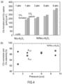
- FIG. 4(a) shows the amounts of CH 4 formed and CO 2 captured using Ni/Al 2 O 3 , or the Ni/Na-Al 2 O 3 bifunctional catalyst, at various pressures. While the amounts of CH 4 formed and CO 2 captured using Ni/Al 2 O 3 were extremely small, high amounts of CH 4 formed and CO 2 captured were observed with the use of the Ni/Na-Al 2 O 3 bifunctional catalyst. Both the amounts of CH 4 formed and CO 2 captured continuously increased with an increase in the reaction pressure.
- FIG. 4(b) shows the CO 2 conversion (X CO2 ) and CH 4 selectivity (S CH4 ) using Ni/Na-Al 2 O 3 , corresponding to each reaction pressure.
- FIG. 5 shows the results of the direct conversion from 100 ppm (Experiment 6) or 300 ppm (Experiment 7) CO 2 to CH 4 using the Ni/Na-Al 2 O 3 catalyst, at 1 atm or 9 atm, with CO 2 supply durations of from 10 to 100 minutes.
- FIGs. 5(a) to 5(d) each shows the results of performing one absorption-conversion sequence (consisting of CO 2 absorption, N 2 purge and CH 4 synthesis) three times sequentially, varying the supply duration of CO 2 in three stages (10 minutes, 30 minutes and 100 minutes).
- FIGs. 5(e) to 5(h) are graphs in which the ordinates of FIGs. 5(a) to 5(d) are enlarged.
- FIG. 6 shows the dependency of the CH 4 formation, the CO formation, the CO 2 absorption, the CO 2 conversion rate and the CH 4 selectivity ( FIGs. 6(a) to 6(e) ), per catalyst mass, on the CO 2 supply duration, at 1 atm and at 9 atm.
- FIGs. 6(a) to 6(e) are the summaries of the experimental results shown in FIGs. 5(a) and 5(c) , obtained by plotting the respective data acquired for CO 2 supply durations of 10 minutes, 30 minutes and 100 minutes.
- the CH 4 selectivity was lower (from 60 to 85%) at 1 atm, and higher (from 90 to 98%) at 9 atm. Since the amount of CO 2 uptake and the CH 4 selectivity can be improved by applying a pressure, as described above, there is a possibility that the amount of catalyst required and/or the reactor size can be reduced.
- the absorption of CO 2 and the reaction with a reducing gas are performed at a pressure higher than the atmospheric pressure, using an absorption-conversion catalyst in which a CO 2 capture component such as an alkali metal or an alkaline earth metal, and a hydrocarbonation catalyst component such as Ni, Fe, Co, Cu or Ru, are supported on an oxide support.
- a CO 2 capture component such as an alkali metal or an alkaline earth metal
- a hydrocarbonation catalyst component such as Ni, Fe, Co, Cu or Ru
- the present invention can be expected to be used for the carbon recycling of CO 2 discharged from power plants, factories and the like, as well as the removal of CO 2 from the atmosphere, and the like.
Landscapes
- Chemical & Material Sciences (AREA)
- Organic Chemistry (AREA)
- Chemical Kinetics & Catalysis (AREA)
- Engineering & Computer Science (AREA)
- Materials Engineering (AREA)
- General Chemical & Material Sciences (AREA)
- Oil, Petroleum & Natural Gas (AREA)
- Catalysts (AREA)
- Organic Low-Molecular-Weight Compounds And Preparation Thereof (AREA)
- Carbon And Carbon Compounds (AREA)
- Production Of Liquid Hydrocarbon Mixture For Refining Petroleum (AREA)
Abstract
Description
- The present invention relates to a method for producing a hydrocarbon compound from carbon dioxide (CO2). More particularly, the present invention relates to a method for producing a hydrocarbon compound from CO2 at concentrations including a low concentration range.
- Conventionally, carbon recycling for absorbing CO2 intensively generated from power plants, steel mills, chemical plants and the like and converting it to methane has been investigated. A method using a two-stage process is known, as an existing means, in which a low concentration of CO2 contained in exhaust gas is separated and captured by a method such as amine absorption or membrane separation to concentrate it to a high concentration, and a hydrocarbon is synthesized by the catalyzed reaction of the highly concentrated CO2 obtained by this concentration.
- Further,
Patent Document 1 discloses, as an example of a methanation catalyst that performs CO2 absorption and conversion, a material in which: a CO2 capture component selected from the group consisting of an alkali metal compound (Li, Na, K, Rb, Cs or the like) and an alkaline earth metal compound (Mg, Ca, Sr, Ba or the like); a methanation catalyst component selected from the group consisting of Ru, Ni and Co; and Si; are supported on an oxide support (such as an alumina support or a titania support).Patent document 1 examines the composition of the catalyst for efficiently carrying out the methanation of CO2 even in cases where a raw material gas contains O2 along with CO2. -
Non-patent Document 1 discloses Ni/K2CO3/MgO and Ni/K2CO3/ZrO2, as CO2 absorption-conversion carrier particles (from 150 to 300 µm) capable of absorbing and converting CO2 with a single material. - Non-patent
Document 2 discloses a dual-functional material (DFM) capable of absorbing and converting CO2 with a single material, and a DFM in which a CO2 capture component (such as Na2O) and a methanation catalyst component (such as Ru) are supported on Al2O3 (alumina) is described therein. -
Non-patent Document 3 describes the direct air capture (DAC) of CO2 contained in the atmosphere. First, K2CO3/Al2O3 in an absorption vessel is allowed to absorb CO2 in the atmosphere, and then a high concentration of CO2 accumulated in the absorption vessel is introduced into another reaction vessel in which an Ru/Al2O3 catalyst is kept, to perform methanation. - [Patent Document 1]
Japanese Patent Application Publication No.2019-188353 -
- [Non-patent Document 1] Koki Nanase et al., Proceeding of SCEJ 85th Annual Meeting (2020), PA162
- [Non-patent Document 2] S. Wang et al., J. of CO2 utilization, Vol. 27, (2018), pp. 390 to 397
- [Non-patent Document 3] J. V. Veselovskaya et al., Energy, Vol. 159, (2018), pp. 766 to 773
- In view of the above-mentioned circumstances, an object of the present invention is to provide a means for directly capturing CO2 at concentrations including a low concentration range by a catalyst itself, without having to perform a CO2 separation operation such as amine absorption or membrane separation, and converting the captured CO2 to a hydrocarbon compound.
- The present inventors and others have conducted intensive studies to solve the above-mentioned problems.
- As a result, the inventors and others have found out that it is possible to efficiency produce a hydrocarbon compound from CO2 at concentrations including a low concentration range, by a method wherein an absorption-conversion catalyst in which a first component such as an alkali metal or an alkaline earth metal and a second component such as Ni, Fe, Co, Cu or Ru are supported on an oxide support is used, and the catalyst is brought into contact with CO2 at a pressure higher than the atmospheric pressure, to produce a hydrocarbon compound.
- According to one embodiment, it is possible to directly capture CO2 at concentrations including a low concentration range without having to perform separation and capture thereof, and to convert the captured CO2 to a hydrocarbon compound at a high efficiency.
-
- [
Fig. 1] FIG. 1 is a schematic diagram illustrating an integrated CO2 capture and conversion system according to an embodiment of the present invention. - [
Fig. 2] FIG. 2 shows the graphs of the measured results of the integrated CO2 capture and conversion to CH4 using bifunctional catalysts at 450°C and under the atmospheric pressure, as compared to that of a catalyst Ni/Al2O3. (a) shows the results using Ni/Al2O3; (b) shows the results using Ni/Na-Al2O3; (c) shows the results using Ni/K-Al2O3; and (d) shows the results using Ni/Ca-Al2O3. The CO2, CH4 and CO concentrations are shown in each graph. Total flow rate: 500 mL/min, pressure: 1 atm. 5% CO2, N2 and H2 were each supplied for 300 seconds, sequentially. - [
Fig. 3] FIG. 3 shows the graphs of the concentrations of the reaction products in the integrated dilute CO2 capture and conversion using the Ni/Na-Al2O3 catalyst at various pressures (from 1 to 9 atm). Total flow rate: 500 mL/min. 5% CO2, N2 and H2 were each supplied for 300 seconds, sequentially. - [
Fig. 4] FIG. 4 shows the graphs of the CO2 capture and conversion performances at various pressures (from 1 to 9 atm). (a) shows the amounts of CH4 formed and CO2 captured, per mass of the catalyst (Ni/Al2O3 or Ni/Na-Al2O3); and (b) shows the CO2 conversion rate (XCO2) and the CH4 selectivity (SCH4) during the integrated dilute CO2 capture and conversion cycle. - [
Fig. 5] FIG. 5 shows the graphs of the concentrations of the reaction products in the integrated dilute CO2 capture and conversion using the Ni/Na-Al2O3 catalyst. (a) and (c) show the results for 100 ppm CO2, and (b) and (d) show the results for 300 ppm CO2; and (a) and (b) show the results at 1 atm, and (c) and (d) show the results at 9 atm. The CO2 supply durations were 10, 30 and 100 minutes. Total flow rate: 500 mL/min. (e) to (h) are enlarged views of (a) to (d). - [
Fig. 6] FIG. 6 shows the graphs of the CO2 capture and conversion performances using Ni/Na-Al2O3 in the integrated dilute CO2 capture and conversion cycle, at 1 atm and at 9 atm. (a) shows the amount of CH4 formed per catalyst mass; (b) shows the amount of CO formed; (c) shows the amount of CO2 absorbed; (d) shows the O2 conversion rate; and (e) shows the CH4 selectivity. - Embodiments of the present invention will be described below.
- An embodiment of the present invention relates to a method for producing a hydrocarbon compound from carbon dioxide, the method including the steps of:
- (a) providing an absorption-conversion catalyst including:
- an oxide support;
- a first component supported on the oxide support and including at least one selected from the group consisting of an alkali metal and an alkaline earth metal; and
- a second component supported on the oxide support and including at least one selected from the group consisting of Ni, Fe, Co, Cu and Ru;
- (b) bringing the absorption-conversion catalyst into contact with a gas containing carbon dioxide at a pressure higher than an atmospheric pressure, to allow the absorption-conversion catalyst to capture carbon dioxide; and
- (c) bringing the absorption-conversion catalyst in which carbon dioxide is captured into contact with a reducing gas at a pressure higher than an atmospheric pressure, to obtain a hydrocarbon compound.
- As described above, techniques for the capture and reuse of a high concentration of carbon dioxide have been investigated. However, a sufficient investigation has not been done for improving the efficiency of the techniques for the capture and reuse of a low concentration of carbon dioxide. The present embodiment has been made based on the finding by the present inventors and others that, by performing reactions at a pressure higher than the atmospheric pressure in the step of allowing the absorption-conversion catalyst to capture carbon dioxide and in the step of converting (hereinafter, also referred to as "hydrocarbonation") carbon dioxide to a hydrocarbon, it is possible to improve the carbon dioxide capture performance of the absorption-conversion catalyst and the carbon dioxide hydrocarbonation performance of the absorption-conversion catalyst. Thus, the present embodiment provides a means for capturing low-concentration CO2 from a gas containing carbon dioxide at concentrations including a low concentration range, without having to separate and concentrate the same, and efficiently producing a hydrocarbon compound. That is, the present embodiment can be expected to be used for the removal of carbon dioxide from the atmosphere containing a low concentration of CO2, and the like.
- In the step (a), an absorption-conversion catalyst comprising: an oxide support; a first component supported on the oxide support and comprising at least one selected from the group consisting of an alkali metal and an alkaline earth metal; and a second component supported on the oxide support and comprising at least one selected from the group consisting of Ni, Fe, Co, Cu and Ru; is provided.
- The term "absorption-conversion catalyst" as used herein refers to a catalyst having an ability to absorb carbon dioxide under predetermined conditions and an ability to convert carbon dioxide to a hydrocarbon compound using a reducing gas.
- The above-described absorption-conversion catalyst comprises: an oxide support; a first component supported on the oxide support and comprising at least one selected from the group consisting of an alkali metal compound and an alkaline earth metal compound; and a second component supported on the oxide support and comprising at least one selected from the group consisting of Ni, Fe, Co, Cu and Ru.
- The oxide support in the absorption-conversion catalyst is not particularly limited as long as it is used as a catalyst support. From the viewpoint of its high activity, however, the oxide support is preferably an alumina support, a silica support, a titania support, a zirconia support, a ceria support, a magnesia support or the like, and more preferably an alumina support. These oxide supports may be used singly, or in combination of two or more kinds thereof.
- The absorption-conversion catalyst preferably has, but not particularly limited to, an average particle size (median diameter, D50) of from 0.1 to 500 µm, more preferably from 1 to 300 µm, and particularly preferably from 50 to 200 µm, from the viewpoint of usability. The absorption-conversion catalyst preferably has a specific surface area of from 10 to 2,000 m2/g, more preferably from 20 to 1,000 m2/g, and particularly preferably from 30 to 500 m2/g, but not particularly limited thereto, as well. The average particle size of the absorption-conversion catalyst can be measured, for example, by the dynamic light scattering method, the small-angle X-ray scattering method, the laser diffraction method or the like. The specific surface area of the absorption-conversion catalyst can be measured, for example, by the gas absorption method, the permeation method or the like.
- The first component comprising at least one selected from the group consisting of an alkali metal and an alkaline earth metal, is a carbon dioxide capture component.
- In the above-described absorption-conversion catalyst, the carbon dioxide capture component is supported on the oxide support. The carbon dioxide capture component selectively captures carbon dioxide, and the captured carbon dioxide is allowed to react with a reducing gas in the presence of a catalyst component for converting carbon dioxide to a hydrocarbon (hereinafter, referred to as "hydrocarbonation catalyst component"), to produce a hydrocarbon compound from carbon dioxide.
- Examples of the carbon dioxide capture component include an alkali metal and an alkaline earth metal. Examples of the alkali metal include Li, Na, K, Rb and Cs. Among these, Na and K are preferred, and Na is particularly preferred. Examples of the alkaline earth metal include Mg, Ca, Sr and Ba. Among these, Ca is preferred from the viewpoint of durability. These carbon dioxide capture components may be used singly, or in combination of two or more kinds thereof.
- When the amount of the carbon dioxide capture component to be supported is too small, the carbon dioxide capture performance of the absorption-conversion catalyst is decreased, and fails to efficiently reduce carbon dioxide, thereby resulting in a decrease in the production efficiency of producing a hydrocarbon compound from carbon dioxide. When the amount of the carbon dioxide capture component to be supported is too large, on the other hand, the coarsening of the carbon dioxide capture component, the pore clogging of the oxide support and the like occur, thereby resulting in a decrease in the carbon dioxide capture performance and the production efficiency of the hydrocarbon compound. From such points of view, the amount of the carbon dioxide capture component to be supported is preferably from 0.1 to 40 parts by mass, more preferably from 1 to 30 parts by mass, and particularly preferably from 5 to 20 parts by mass, with respect to 100 parts by mass of the oxide support.
- The second component comprising at least one selected from the group consisting of Ni, Fe, Co, Cu and Ru is a hydrocarbonation catalyst component.
- In the above-described absorption-conversion catalyst, at least one or a combination of a plurality of hydrocarbonation catalyst components selected from the group consisting of Ni, Fe, Co, Cu and Ru, is/are supported on the oxide support. In the presence of the hydrocarbonation catalyst component, the carbon dioxide captured in the above-described carbon dioxide capture component is allowed to react with a reducing gas, to produce a hydrocarbon compound from carbon dioxide.
- Examples of the hydrocarbonation catalyst component include Ni, Fe, Co, Cu and Ru. Among these, Ni is preferred.
- When the amount of the hydrocarbonation catalyst component to be supported is too small, the reduction reaction of carbon dioxide is not sufficiently facilitated, thereby resulting in a decrease in the production efficiency of producing a hydrocarbon from carbon dioxide. When the amount of the hydrocarbonation catalyst component to be supported is too large, on the other hand, the coarsening of the hydrocarbonation catalyst component, the pore clogging of the oxide support and the like occur, thereby resulting in a decrease in the carbon dioxide capture performance and methane production efficiency. From such points of view, the amount of the hydrocarbonation catalyst component to be supported is preferably from 0.1 to 40 parts by mass, more preferably from 1 to 30 parts by mass and particularly preferably from 5 to 20 parts by mass, with respect to 100 parts by mass of the oxide support.
- The absorption-conversion catalyst described above can be produced based on a known method for producing an absorption-conversion catalyst. For example, the absorption-conversion catalyst can be produced by the method described in the Examples of the present specification.
- In the step (b), the absorption-conversion catalyst is brought into contact with a gas containing carbon dioxide at a pressure higher than an atmospheric pressure, to allow the absorption-conversion catalyst to capture carbon dioxide. In the production method according to the present embodiment, the carbon dioxide capture performance of the absorption-conversion catalyst and the carbon dioxide hydrocarbonation performance of the absorption-conversion catalyst can be improved, by performing the reactions at a pressure higher than the atmospheric pressure. Therefore, it is possible to perform the conversion to a hydrocarbon compound also from a gas containing a low concentration of carbon dioxide.
- The method for adjusting the pressure of the atmosphere in which the absorption-conversion catalyst is allowed to capture carbon dioxide to a pressure higher than the atmospheric pressure is not particularly limited, as long as such a high pressure can be achieved. For example, the method may be one in which a gas containing carbon dioxide, as a raw material, is pressurized and introduced into a reactor, or the like.
- The pressure of the atmosphere in which the absorption-conversion catalyst is allowed to capture carbon dioxide is preferably more than 1 and not more than 9 atm, more preferably from 1.5 to 9 atm, still more preferably from 3 to 9 atm, and particularly preferably from 6 to 9 atm, from the viewpoints of inhibiting the degradation of the catalyst and obtaining a high carbon dioxide capture efficiency.
- The temperature of the atmosphere in which the absorption-conversion catalyst is allowed to capture carbon dioxide can be adjusted as appropriate, depending on the pressure and the like of the atmosphere. However, the temperature is preferably from room temperature to 600°C, from the viewpoints of inhibiting the condensation of moisture to the catalyst and the oxidation of the hydrocarbonation catalyst component.
- The period of time during which the absorption-conversion catalyst is allowed to capture carbon dioxide can be adjusted as appropriate, depending on the pressure, the temperature, the carbon dioxide concentration and the like, of the atmosphere.
- The concentration of carbon dioxide in the gas as the raw material in the production method according to the present embodiment, is not particularly limited. As described above, it is possible to perform the conversion to a hydrocarbon compound also from a gas containing a low concentration of carbon dioxide. Specifically, the conversion to a hydrocarbon compound can be performed also from the air, which is a gas that usually contains carbon dioxide at a low concentration of about 300 ppm. Therefore, it is preferred that the concentration of carbon dioxide in the gas as the raw material be, for example, from 0.01 to 5 vol% (from 100 to 50,000 ppm), more preferably from 0.03 to 5 vol% (from 300 to 50,000 ppm), and still more preferably from 0.04 to 3 vol% (from 400 to 30,000 ppm), and yet still more preferably from 0.1 to 1 vol% (from 1,000 to 10,000 ppm).
- The reducing gas is not particularly limited as long as carbon dioxide can be converted to a hydrocarbon compound. However, pure hydrogen gas or a hydrogen-containing gas is preferred. It is also possible to use a hydrogen gas obtained by water electrolysis using an energy-saving power generation system, as the reducing gas. Another gas(es) to be contained in the hydrogen-containing gas is/are not particularly limited as long as the reduction reaction of carbon dioxide is not inhibited. However, an inert gas such as a helium gas, a nitrogen gas and/or the like is/are preferred. The concentration of hydrogen in the hydrogen-containing gas is preferably 5 vol% or more, and more preferably 10 vol% or more, from the viewpoint of improving the reduction efficiency.
- In the step (c), the absorption-conversion catalyst in which carbon dioxide is captured is brought into contact with a reducing gas at a pressure higher than a atmospheric pressure, to obtain a hydrocarbon compound.
- The method for adjusting the pressure of the atmosphere in which the captured carbon dioxide is allowed to react with a reducing gas to a pressure higher than the atmospheric pressure is not particularly limited as long as such a high can be achieved. For example, the method may be one in which a reducing gas is pressurized and introduced into a reactor, or the like.
- The pressure of the atmosphere in which the captured carbon dioxide is allowed to react with a reducing gas is preferably more than 1 and not more than 9 atm, more preferably from 1.5 to 9, still more preferably from 3 to 9 atm, and particularly preferably from 6 to 9 atm, from the viewpoints of inhibiting the degradation of the catalyst and obtaining a high efficiency for producing a hydrocarbon compound.
- The temperature of the atmosphere in which the captured carbon dioxide is allowed to react with a reducing gas can be adjusted as appropriate, depending on the pressure and the like of the atmosphere. However, the temperature is preferably from 150 to 700°C, and more preferably from 300 to 500°C, from the viewpoints of achieving an improvement in the production rate of the resulting hydrocarbon compound and the inhibition of carbon dioxide desorption during reduction, and obtaining a high efficiency for producing a hydrocarbon compound.
- The period of time during which the captured carbon dioxide is allowed to react with a reducing gas can be adjusted as appropriate, depending on the pressure, the temperature, the carbon dioxide concentration and the like, of the atmosphere.
- The hydrocarbon compound to be obtained in the step (c) is not particularly limited. Examples thereof include hydrocarbons having carbon number of 1 to 5 (such as methane, ethane, propane, n-butane, isobutane, n-pentane, isopentane, neopentane, ethylene and propylene). Among these, methane and ethane are preferred, and methane is more preferred. Further, examples of compounds to be obtained in the step (c), in addition to the hydrocarbon compound, include carbon monoxide (CO) and alcohols (such as methanol and ethanol).
- In the production method according to the present embodiment, the synthesis ratio of the hydrocarbon compound, carbon monoxide (CO) and an alcohol can be adjusted, by adjusting the conditions in the production method based on the Examples to be described later and conventional methods.
- Another embodiment of the present invention relates to an apparatus for carrying out the production method according to the present embodiment,
wherein the apparatus is a circulating fluidized bed type reactor, comprising: - a carbon dioxide capture reactor,
- a hydrocarbon compound synthesis reactor, and
- a catalyst circulation path connecting the carbon dioxide capture reactor and the hydrocarbon compound synthesis reactor.
- The use of a circulating fluidized bed allows the catalyzed reaction of capturing and converting CO2 to proceed continuously. Further, it is possible to allow the catalyzed reaction to proceed at a high flow rate, by using a scaled-up version of such a circulating fluidized bed.
-
FIG. 1 shows an apparatus according to the present embodiment. - The circulating fluidized bed type reactor shown in
FIG. 1 comprises: a carbon dioxide capture reactor for capturing carbon dioxide, by bringing the absorption-conversion catalyst into contact with a gas containing carbon dioxide to allow the absorption-conversion catalyst to capture carbon dioxide; a hydrocarbon compound synthesis reactor for synthesizing a hydrocarbon compound, by bringing the absorption-conversion catalyst in which carbon dioxide is captured into contact with a reducing gas; and a catalyst circulation path provided so as to connect the carbon dioxide capture reactor and the hydrocarbon compound synthesis reactor, and for circulating the catalyst between the two reactors. The circulating fluidized bed in this apparatus is composed of a fluid medium at least a part of which is the absorption-conversion catalyst. - At the lower portion of a container filled with the carbon dioxide capture reactor, a gas delivery pipe for blowing a gas containing carbon dioxide into the container, and a compressor for pressurizing the gas to be introduced into the container are provided. Further, an introduction pipe extending from the catalyst circulation path and for introducing the catalyst into the container is provided at the upper portion of the container. On the side walls of the container, a gas discharge pipe for discharging the gas in the container and a back pressure adjustment valve for decompressing the gas to be discharged out of the container, as well as a discharge pipe extending to the catalyst circulation path and for discharging the catalyst from the container are provided.
- In the carbon dioxide capture reactor, a gas containing carbon dioxide is blown thereinto through the gas delivery pipe to allow the circulating fluidized bed filled in the container to rise. During the above-described process, the circulating fluidized bed is stirred and mixed, and carbon dioxide is captured in the absorption-conversion catalyst.
- The catalyst discharged from the container filled with the carbon dioxide capture reactor is supplied to a container filled with the hydrocarbon compound synthesis reactor, passing through the catalyst circulation path connecting the carbon dioxide capture reactor and the hydrocarbon compound synthesis reactor. A gas replacement unit in which the catalyst is brought into contact with an inert gas is provided in the catalyst circulation path.
- At the lower portion of the container filled with the hydrocarbon compound synthesis reactor, a gas delivery pipe for blowing a reducing gas into the container, and a compressor for pressurizing the gas to be introduced into the container are provided. Further, a discharge pipe extending to the catalyst circulation path and for discharging the catalyst from the container is provided at the upper portion of the container. On the side wall of the container, an introduction pipe extending from the catalyst circulation path and for introducing the catalyst into the container is provided.
- In the hydrocarbon compound synthesis reactor, a gas containing a reducing gas is blown thereinto through the gas delivery pipe to allow the circulating fluidized bed filled in the container to rise. During the above-described process, the circulating fluidized bed is stirred and mixed, the carbon dioxide captured in the absorption-conversion catalyst reacts with the reducing gas, and a hydrocarbon compound is synthesized from the carbon dioxide. At this time, the release of the carbon dioxide captured once in the catalyst is an endothermic reaction, which requires heating. In contrast, the synthesis of the hydrocarbon compound from the carbon dioxide with the reducing gas is an exothermic reaction. Thus, the exothermic reaction and the endothermic reaction proceed simultaneously in the absorption-conversion catalyst during this process, and therefore, the heating for releasing the captured carbon dioxide is supplemented completely or partially, thereby achieves energy saving.
- The catalyst discharged from the container filled with the hydrocarbon compound synthesis reactor is supplied to a capture unit for capturing the catalyst and the like, passing through the catalyst circulation path. In the capture unit, the gas formed and the catalyst are separated, the gas formed is discharged through a discharge pipe, and the catalyst is returned to the carbon dioxide capture reactor through the catalyst circulation path. In the catalyst circulation path, a gas replacement unit in which the catalyst is brought into contact with an inert gas is provided, to separate the gas atmosphere in the carbon dioxide gas absorption reactor from that in the synthesis reactor.
- The present invention will be described in a more specific detail with reference to Examples. However, the present invention is in no way limited to these Examples, as long as the gist of the invention is not deviated.
- Gamma alumina (γ-Al2O3, sample cord: JRC-ALO-5) (particle size range: from 74 to 125 µm) provided by the Catalyst Society of Japan was used without processing. The γ-Al2O3 was impregnated with 50 mL of an aqueous solution containing an appropriate amount of an alkali metal carbonate or an alkaline earth metal nitrate, such as sodium carbonate (Na2(CO3), manufactured by FUJIFILM Wako Pure Chemical Corporation), potassium carbonate (K2(CO3), manufactured by FUJIFILM Wako Pure Chemical Corporation) or calcium carbonate (Ca(NO3)2, manufactured by FUJIFILM Wako Pure Chemical Corporation). Thereafter, the impregnated γ-Al2O3 was dried overnight at 110°C, and baked at 550°C in the air for four hours, to obtain a Na-γ-Al2O3 support, a K-γ-Al2O3 support or a Ca-γ-Al2O3 support. The amount of the alkali metal carbonate or the alkaline earth metal carbonate to be added was maintained at 15% by mass with respect to the amount of γ-Al2O3. Subsequently, Al2O3, the Na-γ-Al2O3 support, the K-γ-Al2O3 support or the Ca-γ-Al2O3 support was impregnated with 50 ml of an aqueous solution of nickel nitrate (Ni(NO3)2·6H2O, manufactured by FUJIFILM Wako Pure Chemical Corporation) by the same procedure and under the same drying and baking conditions. As a result, Ni/Al2O3, Ni/Na-Al2O3, Ni/K-Al2O3 or Ni/Ca-Al2O3 was obtained. The amount of Ni to be added was maintained at 10% by mass with respect to the amount of each support.
- Experiments were carried out based on the following methods.
- One gram of Ni/Al2O3, Ni-Na/Al2O3, Ni/K-Al2O3 or Ni/Ca-Al2O3 catalyst was placed in a SUS pipe in an electric furnace. Before the measurement, each catalyst was pretreated at 500°C in a H2 atmosphere for one hour. To measure the integrated CO2 capture and conversion, x% CO2 (x = from 0.01 to 5) and H2 were sequentially supplied into a reactor for y minutes (y = from 5 to 100) and 5 minutes, respectively. N2 was also supplied for 5 minutes as a purge gas to be used between CO2 and H2 streams. Each measurement was carried out at 450°C, a pressure of from 1 to 9 atm and a rate of 500 mL/min. The outlet gas was monitored using a non-dispersive infrared (NDIR) gas analyzer (VA-5000, manufactured by HORIBA, Ltd.) and a BELMass mass spectrometer. The concentrations of CH4, CO2 and CO in the outlet gas were measured using the NDIR gas analyzer. The reaction temperature was monitored by inserting a thermocouple into the catalyst.
-
FIG. 2 shows the measured results of the CO2 capture and conversion experiments at 450°C and under the atmospheric pressure (1 atm), using various catalysts: Ni/Al2O3 (Experiment 1), Ni/K-Al2O3 (Experiment 2), Ni/Ca-Al2O3 (Experiment 3) and Ni/Na-Al2O3 (Experiment 4). The compositions of the respective catalysts and the measured results using the same are shown in Table 1.[Table 1] Supported amount with respect to 100 parts by mass of oxide carrier [part by mass] Concentration of CO2 supplied [%] Reaction pressure [atm] Amount of CH4 formed [µmol g-cart-1] Ni Na2CO3 K2CO3 CaCO3 Experiment 1 11 0 0 0 5 1 15 Experiment 213 0 17.6 0 5 1 117 Experiment 313 0 0 17.6 5 1 68 Experiment 413 17.6 0 0 5 1 188 Experiment 5 13 17.6 0 0 5 9 303 Experiment 613 17.6 0 0 0.03 9 122 Experiment 7 13 17.6 0 0 0.01 9 106 - First, 5% CO2 was supplied to the reactor to allow the catalyst to absorb CO2. Thereafter, N2 was purged into the gas supply line and to the CO2 in the reactor. Finally, pure H2 was supplied to the reactor, to convert the CO2 absorbed in the catalyst to CH4.
- As shown in
FIG. 2 , Ni/Na-Al2O3 showed the highest activity in the experiments of the integrated CO2 capture and conversion to CH4 under the atmospheric pressure. Further, as shown inFIG. 2(c) , Ni/K-Al2O3 showed a higher efficiency in the conversion to carbon monoxide, CO, than to CH4. - Further, the effects of pressurized conditions (from 1 to 9 atm) and CO2 concentrations (5% and 100 ppm CO2) on the performances of CO2 capture and conversion to CH4 were examined and studied.
-
FIG. 3 shows the measured results of the CO2 capture and conversion experiments at 450°C and at pressures of from 1 to 9 atm. The CH4 formation increased significantly as the reaction pressure increases, and the peak CH4 concentration at 9 atm was about twice that at 1 atm (Experiment 5). The CH4 formation showed a sharp peak under pressurized conditions, namely, even at 9 atm, and the reaction of the absorbed CO2 to CH4 proceeded sufficiently rapidly. -
FIG. 4(a) shows the amounts of CH4 formed and CO2 captured using Ni/Al2O3, or the Ni/Na-Al2O3 bifunctional catalyst, at various pressures. While the amounts of CH4 formed and CO2 captured using Ni/Al2O3 were extremely small, high amounts of CH4 formed and CO2 captured were observed with the use of the Ni/Na-Al2O3 bifunctional catalyst. Both the amounts of CH4 formed and CO2 captured continuously increased with an increase in the reaction pressure.FIG. 4(b) shows the CO2 conversion (XCO2) and CH4 selectivity (SCH4) using Ni/Na-Al2O3, corresponding to each reaction pressure. The amounts of CO2 converted were almost the same between pressures of from 1 to 9 atm, and the CH4 selectivity increased with an increase in the reaction pressure. These results suggest that the reaction pressure has positive effects on the CO2 capture and conversion performances using a bifunctional catalyst such as Ni/Na-Al2O3. - The integrated capture and conversion of 5% CO2 were investigated, as described above, and the application thereof to lower concentrations of CO2 was further investigated. The effects of pressurized conditions on the direct conversion from a dilute CO2, specifically, CO2 at a concentration of 100 ppm or 300 ppm, to CH4 were examined.
-
FIG. 5 shows the results of the direct conversion from 100 ppm (Experiment 6) or 300 ppm (Experiment 7) CO2 to CH4 using the Ni/Na-Al2O3 catalyst, at 1 atm or 9 atm, with CO2 supply durations of from 10 to 100 minutes.FIGs. 5(a) to 5(d) each shows the results of performing one absorption-conversion sequence (consisting of CO2 absorption, N2 purge and CH4 synthesis) three times sequentially, varying the supply duration of CO2 in three stages (10 minutes, 30 minutes and 100 minutes).FIGs. 5(e) to 5(h) are graphs in which the ordinates ofFIGs. 5(a) to 5(d) are enlarged. - As shown in
FIGs. 5(e) and 5(g) , in cases where 100 ppm CO2 was supplied for 10 minutes, the CO2 concentration is extremely low in the outlet gas, suggesting that most of the supplied CO2 was absorbed by the catalyst. In cases where 100 ppm CO2 was supplied for 30 minutes, in contrast, CO2 was observed in the outlet gas at 1 atm, but barely observed at 9 atm, showing that most of CO2 was s absorbed by the catalyst. These results show that the CO2 absorption by the catalyst is increased by applying a pressure. In cases where 100 ppm CO2 was supplied for 100 minutes, the CH4 formation more than doubled when the pressure is increased from 1 atm to 9 atm. While the CO formation proceeded to about the same degree as the CH4 formation at 1 atm, the CO formation was inhibited at 9 atm and a high CH4 selectivity was achieved. -
FIG. 6 shows the dependency of the CH4 formation, the CO formation, the CO2 absorption, the CO2 conversion rate and the CH4 selectivity (FIGs. 6(a) to 6(e) ), per catalyst mass, on the CO2 supply duration, at 1 atm and at 9 atm.FIGs. 6(a) to 6(e) are the summaries of the experimental results shown inFIGs. 5(a) and 5(c) , obtained by plotting the respective data acquired for CO2 supply durations of 10 minutes, 30 minutes and 100 minutes. - As shown in
FIGs. 6(a) and 6(c) , the amounts of the CH4 formed and CO2 captured using the Ni/Na-Al2O3 bifunctional catalyst increased corresponding to an increase in the CO2 supply duration. In the case of 9 atm, in particular, an increase in the CO2 uptake led to a larger increase, in the CO2 supply duration until 100 minutes. These results suggest that pressurized conditions improve the CO2 absorption and enable the CO2 absorption for a longer period of time. As shown inFIG. 6(d) , the CO2 conversion rate was higher than 90% in all reaction conditions using the Ni/Na-Al2O3 catalyst. However, as shown inFIG. 6(e) , the CH4 selectivity was lower (from 60 to 85%) at 1 atm, and higher (from 90 to 98%) at 9 atm. Since the amount of CO2 uptake and the CH4 selectivity can be improved by applying a pressure, as described above, there is a possibility that the amount of catalyst required and/or the reactor size can be reduced. - As described above, it has been shown that it is possible to efficiently produce a hydrocarbon compound from CO2 at concentrations including a low concentration range, by the production method of the Examples. In this production method, the absorption of CO2 and the reaction with a reducing gas are performed at a pressure higher than the atmospheric pressure, using an absorption-conversion catalyst in which a CO2 capture component such as an alkali metal or an alkaline earth metal, and a hydrocarbonation catalyst component such as Ni, Fe, Co, Cu or Ru, are supported on an oxide support.
- As shown in (Experiment 5) to (Experiment 7) in Table 1, it was possible to produce a hydrocarbon compound even in the case of varying the concentration of the supplied CO2 from a high concentration to an extremely low concentration, namely, from 5%, to 0.03% (300 ppm), and then to 0.01% (100 ppm). The 5% CO2 concentration in this case is a high CO2 concentration of 5% or more assuming that discharged from a thermal power plant or the like. Further, 0.03% is a low CO2 concentration assuming that in the atmosphere, and 0.01% is an extremely low CO2 concentration assuming a further lower concentration. As described above, it is possible to directly capture an extremely low to high concentration of CO2 and convert it to a hydrocarbon compound.
- The invention as understood by the disclosure described above can be exemplified as follows.
- [1] A method for producing a hydrocarbon compound from carbon dioxide, the method comprising the steps of
- (a) providing an absorption-conversion catalyst comprising:
- an oxide support;
- a first component supported on the oxide support and comprising at least one selected from the group consisting of an alkali metal and an alkaline earth metal; and
- a second component supported on the oxide support and comprising at least one selected from the group consisting of Ni, Fe, Co, Cu and Ru;
- (b) bringing the absorption-conversion catalyst into contact with a gas containing carbon dioxide at a pressure higher than an atmospheric pressure, to allow the absorption-conversion catalyst to capture carbon dioxide; and
- (c) bringing the absorption-conversion catalyst in which carbon dioxide is captured into contact with a reducing gas at a pressure higher than an atmospheric pressure, to obtain a hydrocarbon compound.
- (a) providing an absorption-conversion catalyst comprising:
- [2] The method according to [1], wherein the pressure in the steps (b) and (c) is more than 1 atm and not more than 9 atm.
- [3] The method according to [1] or [2], wherein a concentration of carbon dioxide in the gas containing carbon dioxide in the step (b) is from 0.01 to 5%.
- [4] The method according to any one of [1] to [3], wherein the first component in the step (a) comprises at least one selected from the group consisting of Na, Ca and K.
- [5] The method according to [4], wherein the first component in the step (a) comprises Na.
- [6] The method according to any one of [1] to [5], wherein the second component in the step (a) comprises Ni.
- [7] The method according to any one of [1] to [6], wherein the absorption-conversion catalyst in the step (a) has an average particle size of from 0.1 to 500 µm.
- [8] The method according to any one of [1] to [7], wherein the oxide support in the step (a) comprises an alumina support.
- [9] The method according to any one of [1] to [8], wherein the reducing gas in the step (c) is a hydrogen-containing gas.
- [10] The method according to any one of [1] to [9], wherein the hydrocarbon compound in the step (c) comprises at least one selected from the group consisting of hydrocarbons having carbon number of 1 to 5.
- [11] The method according to any one of [1] to [10], wherein the hydrocarbon compound in the step (c) comprises at least one selected from the group consisting of methane and ethane.
- [12] The method according to any one of [1] to [11], wherein carbon monoxide is obtained along with the hydrocarbon compound, in step (c).
- [13] An apparatus for carrying out the method according to any one of [1] to [12], wherein the apparatus is a circulating fluidized bed type reactor, comprising:
- a carbon dioxide capture reactor,
- a hydrocarbon compound synthesis reactor, and
- a catalyst circulation path connecting the carbon dioxide capture reactor and the hydrocarbon compound synthesis reactor.
- The present invention can be expected to be used for the carbon recycling of CO2 discharged from power plants, factories and the like, as well as the removal of CO2 from the atmosphere, and the like.
Claims (13)
- A method for producing a hydrocarbon compound from carbon dioxide, the method comprising the steps of(a) providing an absorption-conversion catalyst comprising:an oxide support;a first component supported on the oxide support and comprising at least one selected from the group consisting of an alkali metal and an alkaline earth metal; anda second component supported on the oxide support and comprising at least one selected from the group consisting of Ni, Fe, Co, Cu and Ru;(b) bringing the absorption-conversion catalyst into contact with a gas containing carbon dioxide at a pressure higher than an atmospheric pressure, to allow the absorption-conversion catalyst to capture carbon dioxide; and(c) bringing the absorption-conversion catalyst in which carbon dioxide is captured into contact with a reducing gas at a pressure higher than an atmospheric pressure, to obtain a hydrocarbon compound.
- The method according to claim 1, wherein the pressure in the steps (b) and (c) is more than 1 atm and not more than 9 atm.
- The method according to claim 1 or 2, wherein a concentration of carbon dioxide in the gas containing carbon dioxide in the step (b) is from 0.01 to 5%.
- The method according to any one of claims 1 to 3, wherein the first component in the step (a) comprises at least one selected from the group consisting of Na, Ca and K.
- The method according to claim 4, wherein the first component in the step (a) comprises Na.
- The method according to any one of claims 1 to 5, wherein the second component in the step (a) comprises Ni.
- The method according to any one of claims 1 to 6, wherein the absorption-conversion catalyst in the step (a) has an average particle size of from 0.1 to 500 µm.
- The method according to any one of claims 1 to 7, wherein the oxide support in the step (a) comprises an alumina support.
- The method according to any one of claims 1 to 8, wherein the reducing gas in the step (c) is a hydrogen-containing gas.
- The method according to any one of claims 1 to 9, wherein the hydrocarbon compound in the step (c) comprises at least one selected from the group consisting of hydrocarbons having carbon number of 1 to 5.
- The method according to any one of claims 1 to 10, wherein the hydrocarbon compound in the step (c) comprises at least one selected from the group consisting of methane and ethane.
- The method according to any one of claims 1 to 11, wherein carbon monoxide is obtained along with the hydrocarbon compound, in step (c).
- An apparatus for carrying out the method according to any one of claims 1 to 12,
wherein the apparatus is a circulating fluidized bed type reactor, comprising:a carbon dioxide capture reactor,a hydrocarbon compound synthesis reactor, anda catalyst circulation path connecting the carbon dioxide capture reactor and the hydrocarbon compound synthesis reactor.
Applications Claiming Priority (2)
| Application Number | Priority Date | Filing Date | Title |
|---|---|---|---|
| JP2020134131 | 2020-08-06 | ||
| PCT/JP2021/026401 WO2022030203A1 (en) | 2020-08-06 | 2021-07-14 | Method for manufacturing hydrocarbon compound from carbon dioxide at concentrations including low concentration range |
Publications (2)
| Publication Number | Publication Date |
|---|---|
| EP4194430A1 true EP4194430A1 (en) | 2023-06-14 |
| EP4194430A4 EP4194430A4 (en) | 2025-01-29 |
Family
ID=80119800
Family Applications (1)
| Application Number | Title | Priority Date | Filing Date |
|---|---|---|---|
| EP21852987.3A Pending EP4194430A4 (en) | 2020-08-06 | 2021-07-14 | METHOD FOR PRODUCING A HYDROCARBON COMPOUND FROM CARBON DIOXIDE IN LOW CONCENTRATION RANGE CONCENTRATIONS |
Country Status (4)
| Country | Link |
|---|---|
| US (1) | US12139444B2 (en) |
| EP (1) | EP4194430A4 (en) |
| JP (1) | JP7788153B2 (en) |
| WO (1) | WO2022030203A1 (en) |
Families Citing this family (2)
| Publication number | Priority date | Publication date | Assignee | Title |
|---|---|---|---|---|
| CN115555016A (en) * | 2022-09-27 | 2023-01-03 | 上海交通大学 | Carbon dioxide capturing and converting integrated implementation method based on adsorption/catalysis dual-function material |
| JP2025173529A (en) * | 2024-05-15 | 2025-11-28 | エア・ウォーター・パフォーマンスケミカル株式会社 | Dual-function catalyst for separating and reducing carbon dioxide, method for producing the same, and process using the dual-function catalyst |
Family Cites Families (7)
| Publication number | Priority date | Publication date | Assignee | Title |
|---|---|---|---|---|
| DE102014118894A1 (en) | 2014-12-17 | 2016-07-07 | Muw Screentec Filter- Und Präzisionstechnik Aus Metall Gmbh | Process for carrying out chemical equilibrium reactions using a permselective membrane |
| JP2018135283A (en) * | 2017-02-21 | 2018-08-30 | 株式会社日立製作所 | Method and apparatus for manufacturing methane |
| JP7052360B2 (en) * | 2018-01-12 | 2022-04-12 | 株式会社豊田中央研究所 | Methane production equipment, methane production method |
| JP6991893B2 (en) * | 2018-03-01 | 2022-02-03 | Eneos株式会社 | Carbon dioxide reduction method and carbon dioxide reduction device |
| JP7047575B2 (en) * | 2018-04-26 | 2022-04-05 | 株式会社豊田中央研究所 | Methaneization catalyst and method for producing methane using it |
| CN109453782A (en) * | 2018-11-07 | 2019-03-12 | 中国科学院山西煤炭化学研究所 | The catalyst and preparation method and application of circulation capture carbon dioxide and methanation under calcium oxide constant temperature |
| JP6891869B2 (en) * | 2018-12-25 | 2021-06-18 | 株式会社豊田中央研究所 | Methane production system |
-
2021
- 2021-07-14 EP EP21852987.3A patent/EP4194430A4/en active Pending
- 2021-07-14 US US18/019,490 patent/US12139444B2/en active Active
- 2021-07-14 JP JP2022541184A patent/JP7788153B2/en active Active
- 2021-07-14 WO PCT/JP2021/026401 patent/WO2022030203A1/en not_active Ceased
Also Published As
| Publication number | Publication date |
|---|---|
| US20230295059A1 (en) | 2023-09-21 |
| EP4194430A4 (en) | 2025-01-29 |
| US12139444B2 (en) | 2024-11-12 |
| JPWO2022030203A1 (en) | 2022-02-10 |
| JP7788153B2 (en) | 2025-12-18 |
| WO2022030203A1 (en) | 2022-02-10 |
Similar Documents
| Publication | Publication Date | Title |
|---|---|---|
| Yang et al. | Promotion effects of potassium on the activity and selectivity of Pt/zeolite catalysts for reverse water gas shift reaction | |
| Yan et al. | Improved stability of Y2O3 supported Ni catalysts for CO2 methanation by precursor-determined metal-support interaction | |
| Choudhary et al. | CO-free fuel processing for fuel cell applications | |
| EP4206130A1 (en) | Carbon monoxide production method and device used therefor | |
| Jacobs et al. | Low temperature water-gas shift: kinetic isotope effect observed for decomposition of surface formates for Pt/ceria catalysts | |
| RU2412226C2 (en) | Method of producing and converting synthetic gas (versions) | |
| Jo et al. | Coke-promoted Ni/CaO catal-sorbents in the production of cyclic CO and syngas | |
| CN1914116B (en) | Catalytic reaction between methanol and peroxide | |
| US20230131680A1 (en) | Process and catalyst | |
| US12139444B2 (en) | Method for manufacturing hydrocarbon compound from carbon dioxide at concentrations including low concentration range | |
| Ding et al. | Anti-coking of Yb-promoted Ni/Al2O3 catalyst in partial oxidation of methane | |
| Zurrer et al. | Harnessing the structural attributes of NiMg-CUK-1 MOF for the dual-function capture and transformation of carbon dioxide into methane | |
| Wang et al. | Indium oxide modified with alkali metals: A selective catalyst for the reverse water-gas shift reaction at high pressure | |
| WO2024214059A1 (en) | Nitrogen fixation with water enabled by non-thermal plasma catalytic | |
| Ail et al. | Investigations to intensified hydrogen production via sorption enhanced water gas shift reaction | |
| Liska et al. | Catalytic enhancement of water gas shift reaction with Cu/ZnO/ZSM-5: Overcoming challenges of CO2 and H2 rich feeds | |
| Raskó et al. | CO oxidation in the presence of hydrogen on Au/TiO2 catalyst: an FTIR–MS study | |
| EA036743B1 (en) | Fischer-tropsch process using reductively-activated cobalt catalyst | |
| Luengnaruemitchai et al. | A comparative study of synthesized and commercial A-type zeolite-supported Pt catalysts for selective CO oxidation in H2-rich stream | |
| CA2595466A1 (en) | Catalytically active composition for the selective methanation of carbon monoxide and method for producing said composition | |
| CN115970746B (en) | Method for improving the activity of low-temperature methanation reaction by establishing a hydrophobic catalytic system | |
| Teschner et al. | Surface and structural properties of pt/ceo2catalyst under preferential co oxidation in hydrogen (PROX) | |
| RU2386583C2 (en) | Method of producing gas stream rich in hydrogen | |
| Guo et al. | Steam methane reforming using an anodic alumina supported nickel catalyst (Ni/Al2O3/alloy): analysis of catalyst deactivation | |
| JP7775503B2 (en) | Methane production method |
Legal Events
| Date | Code | Title | Description |
|---|---|---|---|
| STAA | Information on the status of an ep patent application or granted ep patent |
Free format text: STATUS: THE INTERNATIONAL PUBLICATION HAS BEEN MADE |
|
| PUAI | Public reference made under article 153(3) epc to a published international application that has entered the european phase |
Free format text: ORIGINAL CODE: 0009012 |
|
| STAA | Information on the status of an ep patent application or granted ep patent |
Free format text: STATUS: REQUEST FOR EXAMINATION WAS MADE |
|
| 17P | Request for examination filed |
Effective date: 20230209 |
|
| AK | Designated contracting states |
Kind code of ref document: A1 Designated state(s): AL AT BE BG CH CY CZ DE DK EE ES FI FR GB GR HR HU IE IS IT LI LT LU LV MC MK MT NL NO PL PT RO RS SE SI SK SM TR |
|
| DAV | Request for validation of the european patent (deleted) | ||
| DAX | Request for extension of the european patent (deleted) | ||
| A4 | Supplementary search report drawn up and despatched |
Effective date: 20250108 |
|
| RIC1 | Information provided on ipc code assigned before grant |
Ipc: B01J 23/78 20060101ALI20241223BHEP Ipc: B01J 23/74 20060101ALI20241223BHEP Ipc: B01J 23/58 20060101ALI20241223BHEP Ipc: B01J 23/46 20060101ALI20241223BHEP Ipc: B01J 21/04 20060101ALI20241223BHEP Ipc: C07C 9/04 20060101ALI20241223BHEP Ipc: C07C 1/12 20060101AFI20241223BHEP |
|
| STAA | Information on the status of an ep patent application or granted ep patent |
Free format text: STATUS: EXAMINATION IS IN PROGRESS |
|
| 17Q | First examination report despatched |
Effective date: 20250613 |