EP4194385A1 - Yarn processing facility - Google Patents
Yarn processing facility Download PDFInfo
- Publication number
- EP4194385A1 EP4194385A1 EP22208040.0A EP22208040A EP4194385A1 EP 4194385 A1 EP4194385 A1 EP 4194385A1 EP 22208040 A EP22208040 A EP 22208040A EP 4194385 A1 EP4194385 A1 EP 4194385A1
- Authority
- EP
- European Patent Office
- Prior art keywords
- yarn
- unwinding
- supply package
- time
- information
- Prior art date
- Legal status (The legal status is an assumption and is not a legal conclusion. Google has not performed a legal analysis and makes no representation as to the accuracy of the status listed.)
- Granted
Links
Images



Classifications
-
- B—PERFORMING OPERATIONS; TRANSPORTING
- B65—CONVEYING; PACKING; STORING; HANDLING THIN OR FILAMENTARY MATERIAL
- B65H—HANDLING THIN OR FILAMENTARY MATERIAL, e.g. SHEETS, WEBS, CABLES
- B65H63/00—Warning or safety devices, e.g. automatic fault detectors, stop-motions ; Quality control of the package
- B65H63/08—Warning or safety devices, e.g. automatic fault detectors, stop-motions ; Quality control of the package responsive to delivery of a measured length of material, completion of winding of a package, or filling of a receptacle
- B65H63/086—Warning or safety devices, e.g. automatic fault detectors, stop-motions ; Quality control of the package responsive to delivery of a measured length of material, completion of winding of a package, or filling of a receptacle responsive to completion of unwinding of a package
-
- B—PERFORMING OPERATIONS; TRANSPORTING
- B65—CONVEYING; PACKING; STORING; HANDLING THIN OR FILAMENTARY MATERIAL
- B65H—HANDLING THIN OR FILAMENTARY MATERIAL, e.g. SHEETS, WEBS, CABLES
- B65H49/00—Unwinding or paying-out filamentary material; Supporting, storing or transporting packages from which filamentary material is to be withdrawn or paid-out
- B65H49/02—Methods or apparatus in which packages do not rotate
- B65H49/04—Package-supporting devices
- B65H49/10—Package-supporting devices for one operative package and one or more reserve packages
- B65H49/12—Package-supporting devices for one operative package and one or more reserve packages the reserve packages being mounted to permit manual or automatic transfer to operating position
-
- B—PERFORMING OPERATIONS; TRANSPORTING
- B65—CONVEYING; PACKING; STORING; HANDLING THIN OR FILAMENTARY MATERIAL
- B65H—HANDLING THIN OR FILAMENTARY MATERIAL, e.g. SHEETS, WEBS, CABLES
- B65H61/00—Applications of devices for metering predetermined lengths of running material
-
- B—PERFORMING OPERATIONS; TRANSPORTING
- B65—CONVEYING; PACKING; STORING; HANDLING THIN OR FILAMENTARY MATERIAL
- B65H—HANDLING THIN OR FILAMENTARY MATERIAL, e.g. SHEETS, WEBS, CABLES
- B65H67/00—Replacing or removing cores, receptacles, or completed packages at paying-out, winding, or depositing stations
- B65H67/02—Arrangements for removing spent cores or receptacles and replacing by supply packages at paying-out stations
-
- B—PERFORMING OPERATIONS; TRANSPORTING
- B65—CONVEYING; PACKING; STORING; HANDLING THIN OR FILAMENTARY MATERIAL
- B65H—HANDLING THIN OR FILAMENTARY MATERIAL, e.g. SHEETS, WEBS, CABLES
- B65H67/00—Replacing or removing cores, receptacles, or completed packages at paying-out, winding, or depositing stations
- B65H67/04—Arrangements for removing completed take-up packages and or replacing by cores, formers, or empty receptacles at winding or depositing stations; Transferring material between adjacent full and empty take-up elements
- B65H67/0405—Arrangements for removing completed take-up packages or for loading an empty core
-
- B—PERFORMING OPERATIONS; TRANSPORTING
- B65—CONVEYING; PACKING; STORING; HANDLING THIN OR FILAMENTARY MATERIAL
- B65H—HANDLING THIN OR FILAMENTARY MATERIAL, e.g. SHEETS, WEBS, CABLES
- B65H67/00—Replacing or removing cores, receptacles, or completed packages at paying-out, winding, or depositing stations
- B65H67/04—Arrangements for removing completed take-up packages and or replacing by cores, formers, or empty receptacles at winding or depositing stations; Transferring material between adjacent full and empty take-up elements
- B65H67/044—Continuous winding apparatus for winding on two or more winding heads in succession
-
- B—PERFORMING OPERATIONS; TRANSPORTING
- B65—CONVEYING; PACKING; STORING; HANDLING THIN OR FILAMENTARY MATERIAL
- B65H—HANDLING THIN OR FILAMENTARY MATERIAL, e.g. SHEETS, WEBS, CABLES
- B65H67/00—Replacing or removing cores, receptacles, or completed packages at paying-out, winding, or depositing stations
- B65H67/06—Supplying cores, receptacles, or packages to, or transporting from, winding or depositing stations
-
- B—PERFORMING OPERATIONS; TRANSPORTING
- B65—CONVEYING; PACKING; STORING; HANDLING THIN OR FILAMENTARY MATERIAL
- B65H—HANDLING THIN OR FILAMENTARY MATERIAL, e.g. SHEETS, WEBS, CABLES
- B65H2701/00—Handled material; Storage means
- B65H2701/30—Handled filamentary material
- B65H2701/31—Textiles threads or artificial strands of filaments
Definitions
- the present invention relates to a yarn processing facility.
- Patent Literature 1 (Published Japanese Translation of a PCT application No. 2003-526584 ) discloses an apparatus (yarn processing facility) configured to form each winding assembly (wound package) by processing a yarn unwound from a yarn supply package (supply bobbin in Patent Literature 1) and winding the yarn onto a winding bobbin.
- the yarn supply package is formed by winding a yarn onto a yarn supplying bobbin.
- the yarn processing facility is able to support two yarn supply packages for one winding bobbin.
- An object of the present invention is to accurately estimate a timing of the end of unwinding of a yarn from a yarn supply package.
- a yarn processing facility includes: a yarn processor including a yarn supplying unit which is able to supply at least one yarn, a processing unit configured to process the at least one yarn supplied from the yarn supplying unit, and a winding unit configured to wind the at least one yarn processed by the processing unit; and an information management unit configured to manage information regarding the yarn processor, the yarn supplying unit including: at least one yarn supply package retaining portion to which yarn supply packages each including a yarn are detachably attached and which is able to uninterruptedly supply each yarn when a terminal portion of a yarn in one yarn supply package among the yarn supply packages is connected to a start end portion of a yarn in a next yarn supply package from which the yarn is to be unwound next to the one yarn supply package; and at least one detection unit which is able to detect at least whether unwinding of a yarn from the one yarn supply package ends, and the information management unit being configured to: acquire actual all unwinding time information regarding actual all unwinding time by using a detection result of the
- the timing of the end of the unwinding of the yarn from the second yarn supply package is estimated based on the corrected estimation information which is acquired by using the actual all unwinding time information regarding actual time from the start to end of unwinding of a yarn from the first yarn supply package. It is therefore possible to accurately estimate a timing of the end of unwinding of a yarn from a yarn supply package.
- the yarn processing facility of the first aspect is arranged such that the information management unit is further configured to exclude stopping time, in which unwinding of a yarn from the first yarn supply package is temporarily stopped, from the actual all unwinding time when the stopping time exists between the start and end of the unwinding of the yarn from the first yarn supply package.
- the yarn processing facility of the first or second aspect is arranged such that the information management unit is further configured to: store information of at least one system value which is usable for estimating a timing of the end of unwinding of a yarn from the first yarn supply package in advance; calculate at least one predetermined correction value by using the at least one system value and the actual all unwinding time; and acquire the corrected estimation information by using the at least one correction value and the at least one system value.
- the end timing When a timing (hereinafter, this timing will be simply referred to as the end timing) of the end of unwinding of a yarn from a yarn supply package is estimated by a calculation, a difference between the calculated end timing and an actual end timing may be large because of a difference between the at least one stored system value and an actual value of one of various parameters which have effects on the actual end timing.
- the at least one correction value is calculated based on the actual all unwinding time, and the corrected estimation information is acquired by using the at least one correction value. It is therefore possible to acquire various types of accurate information.
- the yarn processing facility of the third aspect is arranged such that system values include an initial weight setting value which is a setting value of initial weight of the first yarn supply package, a fineness setting value which is a setting value of fineness of a yarn in the first yarn supply package, and an unwinding speed setting value which is a setting value of unwinding speed at which the yarn is unwound from the first yarn supply package.
- the end timing is estimated by using information which can be typically easily acquired as one of the system values.
- the yarn processing facility of the third or fourth aspect is arranged such that the information management unit is further configured to: be able to calculate initially-estimated all unwinding time, which is an estimated value of time from the start to end of unwinding of a yarn from the first yarn supply package, by using the system values; and acquire, as the at least one correction value, a time correction coefficient calculated by dividing the actual all unwinding time by the initially-estimated all unwinding time.
- the end timing of the second yarn supply package is accurately estimated by multiplying the initially-estimated all unwinding time by the time correction coefficient.
- the yarn processing facility of the third or fourth aspect is arranged such that the information management unit is further configured to: be able to calculate initially-estimated all unwinding time, which is an estimated value of time from the start to end of unwinding of a yarn from the first yarn supply package, by using the system values; and acquire, as the at least one correction value, a difference value between the actual all unwinding time and the initially-estimated all unwinding time.
- the end timing of the second yarn supply package is accurately estimated on the premise that the initial length of a yarn in the first yarn supply package is substantially identical with the initial length of a yarn in the second yarn supply package.
- the yarn processing facility of the fourth aspect is arranged such that the information management unit is further configured to acquire a fineness correction coefficient as the at least one correction value by using the actual all unwinding time, the initial weight setting value, the fineness setting value, and the unwinding speed setting value, and the fineness correction coefficient is usable for correcting the fineness.
- the yarn processing facility of any one of the third to seventh aspects is arranged such that the information management unit is further configured to: after acquiring an initial correction value which is the at least one correction value of the first yarn supply package, acquire an additional correction value which is the at least one correction value of an additional yarn supply package which is different from the first yarn supply package and which is retained by the at least one yarn supply package retaining portion; and acquire an update correction value by using at least the additional correction value.
- the update correction value is acquired by using at least the additional correction value
- the following both cases are possible: a case where the update correction value is acquired by a calculation with use of the initial correction value and the additional correction value; and a case where the additional correction value is acquired as the update correction value.
- the accuracy of estimation is further increased by acquiring the update correction value according to need and acquiring, with use of the update correction value, the corrected estimation information.
- the yarn processing facility of any one of the third to eighth aspects is arranged such that the yarn processor is able to simultaneously process yarns, the yarn supplying unit includes yarn supply package retaining portions and detection units provided to correspond to the yarn supply package retaining portions, and the information management unit is further configured to: acquire correction values of the yarn supply package retaining portions by using detection results of the detection units; acquire an integrated correction value by using the correction values; and acquire the corrected estimation information of the yarn supply package retaining portions by using the integrated correction value and the system values.
- the accuracy of estimation is further increased by acquiring the integrated correction value with use of the correction values.
- the yarn processing facility of the ninth aspect is arranged such that the integrated correction value is an average value or a median of the correction values.
- the very reliable integrated correction value is acquired with a simple calculation.
- the yarn processing facility of any one of the third to tenth aspects is arranged such that the yarn processor is able to simultaneously process yarns, the yarn supplying unit includes yarn supply package retaining portions and detection units provided to correspond to the yarn supply package retaining portions, the information management unit is further configured to: acquire at least one correction value by using a detection result of one of the detection units; and acquire the corrected estimation information of the yarn supply package retaining portions by using the at least one correction value and the system values.
- the start of acquisition of the corrected estimation information may be delayed.
- the corrected estimation information of the yarn supply package retaining portions is immediately acquired. It is therefore possible to quickly start the accurate estimation in each of the yarn supply package retaining portions.
- the yarn processing facility of the first or second aspect is arranged such that the information management unit is further configured to deal with the actual all unwinding time as the corrected estimation information.
- a timing of the end of unwinding of a yarn from the second yarn supply package is estimated by a simple process on the premise that the initial length of a yarn in the first yarn supply package is substantially identical with the initial length of a yarn in the second yarn supply package.
- the yarn processing facility of any one of the first to twelfth aspects is arranged such that the information management unit is further configured to acquire, as the corrected estimation information, at least one of: information of corrected estimation time which is an estimated value of time from the start to end of unwinding of a yarn from the second yarn supply package; information of a corrected unwinding end time point which is a time point at which the unwinding of the yarn from the second yarn supply package ends; information of corrected remaining time which is remaining time in which the unwinding of the yarn from the second yarn supply package is possible at a given reference time point; and information of a corrected remaining amount which is a remaining amount of the yarn in the second yarn supply package at the reference time point.
- the acquired corrected estimation information is utilized for various managements (e.g., preparation of a schedule of replacement of a yarn supply package).
- the yarn processing facility of any one of the first to thirteenth aspects is arranged such that the at least one detection unit is able to detect both the start and end of unwinding of a yarn from the one yarn supply package.
- the information management unit may be configured to determine a timing of the start of the unwinding in such a way that an operator makes a predetermined input in the information management unit.
- this arrangement increases the burden on the operator.
- the burden on the operator is reduced.
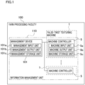
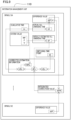
- a yarn processing facility 100 of the present embodiment will be outlined with reference to a block diagram of FIG. 1 .
- the yarn processing facility 100 includes false-twist texturing machines 1 (yarn processors of the present invention) and a management device 101.
- the false-twist texturing machines 1 are aligned along, e.g., a predetermined frame longitudinal direction (see FIG. 2 , etc.).
- Each false-twist texturing machine 1 is able to perform false twisting of yarns Y (see FIG. 2 , etc.) made of synthetic fibers such as polyester and nylon (polyamide fibers).
- Each yarn Y is, e.g., a multi-filament yarn formed of filaments (not illustrated).
- each false-twist texturing machine 1 is configured to form wound packages Pw by processing yarns Y supplied from a yarn supplying unit 2 by means of a processing unit 3 and winding the yarns Y onto winding bobbins Bw attached to a winding unit 4.
- Each false-twist texturing machine 1 is controlled by a machine controller 5 that is a computer device mounted on each false-twist texturing machine 1.
- the management device 101 is a host computer used for integrally controlling information acquired by machine controllers 5.
- the management device 101 includes a management input unit 101a (e.g., a keyboard), a management output unit 101b (e.g., a display), and a management storage unit 101c (e.g., a hard disk).
- a combination of the management device 101 and the machine controllers 5 is an information management unit 110 of the present embodiment. The information dealt with by the information management unit 110 will be detailed later.
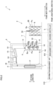
- FIG. 2 is a profile of each false-twist texturing machine 1.
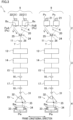
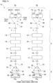
- FIG. 3 is a schematic diagram of the false-twist texturing machine 1, expanded along paths of yarns Y (i.e., yarn paths).
- a direction vertical to the sheet of FIG. 2 is defined as the above-described frame longitudinal direction, and a left-right direction in the sheet is defined as a frame width direction.
- a direction orthogonal to both the frame longitudinal direction and the frame width direction is defined as an up-down direction (vertical direction) in which the gravity acts.
- a direction in which each yarn Y runs is defined as a yarn running direction.
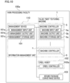
- the false-twist texturing machine 1 includes a yarn supplying unit 2 provided for supplying yarns Y, a processing unit 3 configured to process (false-twist) the yarns Y supplied from the supplying unit 2, a winding unit 4 configured to wind the yarns Y processed by the processing unit 3 onto winding bobbins Bw, and a corresponding machine controller 5.
- the yarn supplying unit 2 includes a creel stand 6 retaining yarn supply packages Ps, and is configured to supply the yarns Y to the processing unit 3.
- the processing unit 3 is configured to unwind the yarns Y from the yarn supplying unit 2 and to process the yarns Y.
- the following members are placed in this order from the upstream side in the yarn running direction: first feed rollers 11; twist-stopping guides 12; first heaters 13; coolers 14; false-twisting devices 15; second feed rollers 16; second heaters 17; and third feed rollers 18.
- Each of these elements of the processing unit 3 is provided for, e.g., each of later-described spindles 9 (see FIG. 3 ).
- the winding unit 4 includes plural winding devices 19.
- Each winding device 19 is configured to wind a yarn Y for which false twisting has been performed by the processing unit 3 onto a winding bobbin Bw and to form a wound package Pw.
- the winding unit 4 is provided with automatic doffers 10 which correspond to the respective winding devices 19 and which are configured to replace formed wound packages Pw with empty winding bobbins Bw.
- the machine controller 5 is configured to control the yarn supplying unit 2, the processing unit 3, and the winding unit 4.
- the machine controller 5 is, e.g., a typical computer device.
- the machine controller 5 includes a machine input unit 5a (operation unit of the present invention), a machine output unit 5b, and a machine storage unit 5c (see FIG. 1 ).
- the machine input unit 5a is, e.g., an unillustrated touch panel and/or keyboard and is operable by an operator.
- the machine output unit 5b includes, e.g., an unillustrated display and is able to output information.
- the machine storage unit 5c is arranged to store various types of information used for controlling the yarn supplying unit 2, processing unit 3, and winding unit 4.
- the machine controller 5 controls the yarn supplying unit 2, processing unit 3, and winding unit 4.
- the machine controller 5 may indirectly control the yarn supplying unit 2, processing unit 3, and winding unit 4 through unillustrated controllers (not illustrated) configured to control these members.
- the machine controller 5 is electrically connected to the management device 101 that is a host computer.
- the management device 101 is able to perform later-described determinations and/or calculations by using information acquired by the machine controller 5.
- the false-twist texturing machine 1 includes a main frame 7 and a winding base 8 that are spaced apart from each other in the frame width direction.
- the main frame 7 and the winding base 8 are substantially identical in length in the frame longitudinal direction.
- the main frame 7 and the winding base 8 oppose each other in the frame width direction.
- the false-twist texturing machine 1 includes units which are termed spans each of which includes a pair of the main frame 7 and the winding base 8. In one span, each device is placed so that the false twisting is simultaneously performable for the yarns Y running while being aligned in the frame longitudinal direction.
- the spans are placed in a left-right symmetrical manner to the sheet, with a center line C of the frame width direction of the main frame 7 being set as a symmetry axis (main frame 7 is shared between the left span and the right span).
- the spans are aligned in the frame longitudinal direction.
- the false-twist texturing machine 1 includes the spindles 9 (see FIG. 3 ) the number of which is identical with the number of wound packages Pw that can be simultaneously formed. Roughly speaking, the spindles 9 are aligned along the frame longitudinal direction.
- the inclusion relation is as follows: one false-twist texturing machine 1 includes plural spans, and each of the spans includes plural spindles 9. The false-twist texturing machine 1 is able to false-twist the yarns Y at the spindles 9 to which the yarns Y are threaded.
- the creel stand 6 of the yarn supplying unit 2 includes yarn supply package retaining portions 20 (see FIG. 3 ) provided to correspond to the respective spindles 9.
- Each yarn supply package retaining portion 20 is arranged so that two yarn supply packages Ps are attachable thereto and detachable therefrom.
- each yarn supply package retaining portion 20 has two package attachment units 21.
- one of the two package attachment units 21 is termed a first attachment unit 22, and the other of these units is termed a second attachment unit 23.
- Each of the first attachment unit 22 and the second attachment unit 23 is arranged so that one yarn supply package Ps is attachable thereto and detachable therefrom.
- the attachment and detachment of each yarn supply package Ps to and from a corresponding package attachment unit 21 are performed by, e.g., an operator.
- Each yarn supply package retaining portion 20 of the yarn supplying unit 2 is able to uninterruptedly supply a yarn Y in a manner described below.
- one of the yarn supply packages Ps i.e., a yarn supply package PsA (one yarn supply package of the present invention) is attached to the first attachment unit 22.
- the other of the yarn supply packages Ps i.e., a yarn supply package PsB (next yarn supply package of the present invention) is attached to the second attachment unit 23.
- the yarn Y is unwound from the yarn supply package PsA.
- a terminal portion of the yarn Y in the yarn supply package PsA is tied (connected) to a start end portion of a yarn Y in the yarn supply package PsB.
- a node K (yarn connecting portion) is formed between two yarns Y. This makes it possible to uninterruptedly supply the yarn Y from the yarn supply package PsB after the yarn supply package PsA becomes empty.
- the node K is pulled toward the downstream side in the yarn running direction (i.e., toward the winding device 19) so that the yarn Y is unwound from the yarn supply package PsB.
- a yarn detection sensor 24 (detection unit of the present invention) is provided on the downstream side in the yarn running direction of each yarn supply package retaining portion 20, a yarn detection sensor 24 (detection unit of the present invention) is provided.
- the yarn detection sensor 24 is able to detect which one of the attachment units, i.e., the first attachment unit 22 and or second attachment unit 23 is supplying the yarn Y.
- the yarn detection sensor 24 includes a first detection unit 25 and a second detection unit 26.
- the first detection unit 25 is able to detect whether the yarn Y is being supplied from the first attachment unit 22.
- the second detection unit 26 is able to detect whether the yarn Y is being supplied from the second attachment unit 23.
- Each of the first detection unit 25 and the second detection unit 26 is, e.g., an optical sensor configured to optically detect the yarn Y.
- each of the first detection unit 25 and the second detection unit 26 may be, e.g., a contact sensor.
- processing unit 3 The structure of the processing unit 3 will be described with reference to FIG. 2 and FIG. 3 . The following will describe a part of the processing unit 3, which corresponds to one spindle 9.
- a first feed roller 11 is configured to unwind a yarn Y from one yarn supply package Ps attached to the yarn supplying unit 2 and to feed the yarn Y to a first heater 13.
- the first feed roller 11 is provided upstream of a twist-stopping guide 12 in the yarn running direction.
- the conveyance speed of conveying the yarn Y by the first feed roller 11 is substantially identical with an unwinding speed V (see FIG. 3 ; hereinafter, this may be referred to as just the unwinding speed) at which the yarn Y is unwound from the yarn supply package Ps.
- information indicating a setting value of the conveyance speed of conveying the yarn Y by the first feed roller 11 is stored in, e.g., the machine controller 5 in advance.
- An unillustrated cutter may be provided upstream of the first feed roller 11 in the yarn running direction.
- the yarn Y is cut by the cutter so that the yarn Y is prevented from being unintentionally wound onto a rotating member such as the first feed roller 11.
- the twist-stopping guide 12 is provided to prevent twist of the yarn Y from being propagated to the upstream side of the twist-stopping guide 12 in the yarn running direction.
- the twist of the yarn Y is formed by a false-twisting device 15.
- the twist-stopping guide 12 is provided downstream of the first feed roller 11 in the yarn running direction and upstream of a first heater 13 in the yarn running direction.
- the first heater 13 is configured to heat the yarn Y fed from the first feed roller 11.
- the first heater 13 is provided downstream of the twist-stopping guide 12 in the yarn running direction and upstream of a cooler 14 in the yarn running direction.
- the first heater 13 of the present embodiment is configured to heat a single yarn Y.
- the first heater 13 may be able to simultaneously heat plural yarns Y.
- the cooler 14 is configured to cool the yarn Y heated by the first heater 13.
- the cooler 14 is provided downstream of the first heater 13 in the yarn running direction and upstream of the false-twisting device 15 in the yarn running direction.
- the cooler 14 of the present embodiment is configured to cool a single yarn Y.
- the cooler 14 may be able to simultaneously cool plural yarns Y.
- the false-twisting device 15 is configured to twist the yarn Y.
- the false-twisting device 15 is, e.g., a so-called disc-friction false-twisting device. However, the disclosure is not limited to this.
- the false-twisting device 15 is provided downstream of the cooler 14 in the yarn running direction and upstream of a second feed roller 16 in the yarn running direction.
- the second feed roller 16 is configured to feed the yarn Y processed by the false-twisting device 15 to a second heater 17.
- the conveyance speed of conveying the yarn Y by the second feed roller 16 is higher than the conveyance speed of conveying the yarn Y by the first feed roller 11.
- the yarn Y is therefore drawn between the first feed roller 11 and the second feed roller 16.
- information indicating a setting value of the conveyance speed of conveying the yarn Y by the second feed roller 16 is stored in, e.g., the machine controller 5 in advance.
- the second heater 17 is configured to heat the yarn Y fed from the second feed roller 16.
- the second heater 17 extends along the vertical direction.
- the second heater 17 of the present embodiment is configured to heat a single yarn Y.
- the disclosure is not limited to this.
- the second heater 17 may be able to simultaneously heat plural yarns Y.
- a third feed roller 18 is configured to feed the yarn Y heated by the second heater 17 to a winding device 19.
- the conveyance speed of conveying the yarn Y by the third feed roller 18 is lower than the conveyance speed of conveying the yarn Y by the second feed roller 16.
- the yarn Y is therefore relaxed between the second feed roller 16 and the third feed roller 18.
- information indicating a setting value of the conveyance speed of conveying the yarn Y by the third feed roller 18 is stored in, e.g., the machine controller 5 in advance.
- the yarn Y drawn between the first feed roller 11 and the second feed roller 16 is twisted by the false-twisting device 15.
- the twist formed by the false-twisting device 15 propagates to the twist-stopping guide 12, but does not propagate to the upstream side of the twist-stopping guide 12 in the yarn running direction.
- the yarn Y which is twisted and drawn is heated by the first heater 13 and thermally set. After that, the yarn Y is cooled by the cooler 14.
- the yarn Y is untwisted on the downstream side of the false-twisting device 15 in the yarn running direction.
- each filament is maintained to be wavy in shape on account of the thermal setting described above.
- the yarn Y false-twisted by the false-twisting device 15 is thermally set by the second heater 17 while being relaxed between the second feed roller 16 and the third feed roller 18, and then the yarn Y is guided to the downstream side in the yarn running direction.
- the yarn Y fed from the third feed roller 18 is wound onto a winding bobbin Bw by the winding device 19. As a result, one wound package Pw is formed.
- the winding unit 4 includes (i) the winding devices 19 configured to wind yarns Y onto winding bobbins Bw and (ii) the automatic doffers 10 (see FIG. 2 ) provided to correspond to the respective winding devices 19.
- One winding device 19 belongs to one spindle 9 (see FIG. 3 ).
- Each winding device 19 includes, e.g., a fulcrum guide 31, a traverse unit 32, a cradle 33, and a winding roller 34.
- the fulcrum guide 31 is a guide which is a fulcrum when a yarn Y is traversed.
- the traverse unit 32 is configured to traverse the yarn Y by means of, e.g., a traverse guide 35 attached to an endless belt driven by a motor in a reciprocating manner.
- the cradle 33 is able to support a winding bobbin Bw (wound package Pw) to be rotatable.
- the winding roller 34 is configured to rotate the wound package Pw and to apply contact pressure to the surface of the wound package Pw.
- the winding roller 34 is, e.g., rotationally driven by an unillustrated motor while being in contact with the surface of the wound package Pw. With this arrangement, the wound package Pw is rotationally driven by the friction force, and the shape of the wound package Pw is adjusted by the contact pressure applied to the surface of the wound package Pw.
- the wound package Pw may be directly rotated by an unillustrated motor.
- Each automatic doffer 10 is configured to detach the wound package Pw from the winding device 19 and to attach an empty winding bobbin Bw to the winding device 19. To put it differently, at the winding unit 4, the automatic doffer 10 is able to replace a wound package Pw having been formed with an empty winding bobbin Bw.
- the automatic doffer 10 is provided with an unillustrated cutter which is able to cut the yarn Y in the vicinity of the wound package Pw. As the running yarn Y is cut by the cutter, formation of the wound package Pw is finished.
- the automatic doffer 10 includes an unillustrated suction which is able to suck, capture, and retain the running yarn Y supplied to the winding device 19, in a period from the finish of the formation of the wound package Pw to start of winding of the yarn Y onto the next winding bobbin Bw.
- a part of the yarn Y sucked by the suction is sucked and removed.
- an unillustrated yarn threading device is provided in the vicinity of the winding device 19.
- the yarn threading device is configured to thread the yarn Y onto the empty winding bobbin Bw attached to the winding device 19.
- the yarn Y which is fed from the above-described third feed roller 18 is wound onto the winding bobbin Bw by each winding device 19, and the wound package Pw is formed (winding process).
- the cutter of the automatic doffer 10 cuts the yarn Y
- the winding process of winding the yarn Y onto the winding bobbin Bw is finished.
- the yarn Y supplied to the winding device 19 is sucked and retained by the suction, and the wound package Pw is detached from the cradle 33 by the automatic doffer 10.
- the automatic doffer 10 attaches a new winding bobbin Bw to the cradle 33.
- the yarn threading device threads the yarn Y to the new winding bobbin Bw. Thereafter, it becomes possible to start winding of the yarn Y onto the new winding bobbin Bw.
- the inventors of the subject application conceived of an idea described below, in order to significantly improve production management as compared to known production management.
- the inventors of the subject application conceived of an idea of providing a means for knowing, at a desired timing, (i) the remaining amount of the yarn Y (yarn remaining amount; hereinafter, this may be referred to as just the remaining amount) after a part of the yarn Y is unwound from the yarn supply package Ps and/or (ii) the time (remaining time; hereinafter, this may be referred to as just the remaining time) in which the yarn Y can be supplied from the yarn supply package Ps.
- the time from the start to end of unwinding of the yarn Y from the yarn supply package Ps i.e., to running out of the yarn Y in the yarn supply package Ps
- a timing of running out of the yarn Y in the yarn supply package Ps from which the yarn Y is unwound can be estimated.
- the information management unit 110 is configured to perform information processing described later in order to accurately estimate a timing of the end of unwinding of the yarn Y from the yarn supply package Ps.
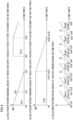
- the information management unit 110 is configured to acquire and manage various types of information regarding matters shown in graphs of FIG. 4(a) to FIG. 4(c) . Unless otherwise stated, the following explanation deals with only a predetermined spindle 9 among the spindles 9.
- the information management unit 110 is configured to acquire information of at least one of the matters shown in the graphs of FIG. 4(a) to FIG. 4(c) . (The details will be given later.)
- Each time point described below is not a time point which is estimated by any means but a time point at which a corresponding matter actually occurs.
- FIG. 4(a) is a graph showing the relationship between the remaining amount (vertical axis) of a yarn Y in each yarn supply package Ps (to be more specific, yarn supply packages Ps1, Ps3) attached to the first attachment unit 22 and time points (horizontal axis).
- FIG. 4(b) is a graph showing the relationship between the remaining amount (vertical axis) of the yarn Y in each yarn supply package Ps (to be more specific, a yarn supply package Ps2) attached to the second attachment unit 23 and time points (horizontal axis).
- FIG. 4(a) is a graph showing the relationship between the remaining amount (vertical axis) of a yarn Y in each yarn supply package Ps (to be more specific, a yarn supply package Ps2) attached to the second attachment unit 23 and time points (horizontal axis).
- FIG. 4(c) is a graph showing the relationship between the wound amount (vertical axis) of a yarn Y onto each winding bobbin Bw (to be more specific, winding bobbins Bw1, Bw2, Bw3, Bw4, Bw5, and Bw6) and time points (horizontal axis).
- a time point t0 at which unwinding of a yarn Y from the yarn supply package Ps1 starts is the origin.
- the weight (initial weight; hereinafter, this may be referred to as just the initial weight) of each yarn supply package Ps in a state in which a yarn Y is not unwound from each yarn supply package Ps at all (i.e., fully-wound yarn supply package Ps) is always WF.
- the fully wound yarn supply package Ps1 is attached to the first attachment unit 22.
- the weight of the yarn Y in the yarn supply package Ps1 is identical with the initial weight WF.
- the fully-wound yarn supply package Ps2 is attached to the second attachment unit 23.
- a terminal portion of the yarn Y in the yarn supply package Ps1 is tied to a start end portion of a yarn Y in the yarn supply package Ps2, and hence a node K is formed.
- yarn threading to each element at the spindle 9 starts.
- unwinding of the yarn Y from the fully-wound yarn supply package Ps1 starts.
- the yarn threading to the winding bobbin Bw1 attached to the winding device 19 is completed and winding of the yarn Y onto the winding bobbin Bw1 starts.
- the yarn Y is sucked and captured by the suction until the yarn threading to the winding bobbin Bw1 is completed.
- the unwinding speed of the yarn Y in the yarn threading is substantially identical with the unwinding speed (the above-described unwinding speed V) in the winding of the yarn Y onto the winding bobbin Bw.
- a difference between the time point ts1 and the time point t0 is the time from the start to completion of the yarn threading.
- the remaining amount (remaining weight) of the yarn Y in the yarn supply package Ps1 decreases and the wound amount (wound weight) of the yarn Y wound on the winding bobbin Bw1 increases over time.
- the time point te1 is a winding end time point at which the winding of the yarn Y onto the winding bobbin Bw1 ends (i.e., the formation of the wound package Pw1 ends).
- the remaining weight of the yarn supply package Ps1 at this time is W1.
- the winding process of winding the yarn Y onto the winding bobbin Bw2 ends at a time point te2.
- the winding process of winding the yarn Y onto the winding bobbin Bw3 then starts at a time point ts3.
- the yarn supply package Ps1 attached to the first attachment unit 22 becomes empty. Therefore, the time point ta1 is an unwinding end time point at which the unwinding of the yarn Y from the yarn supply package Ps1 ends.
- the node K formed as the yarn Y in the yarn supply package Ps1 is tied with the yarn Y in the yarn supply package Ps2 is pulled toward the winding device 19. As a result, the yarn Y starts to be unwound from the yarn supply package Ps2 attached to the second attachment unit 23.
- the time point tb1 is an unwinding start time point at which the unwinding of the yarn Y from the yarn supply package Ps2 starts (i.e., the yarn Y starts to be unwound) .
- the winding process of winding the yarn Y onto the winding bobbin Bw3 i.e., formation of the wound package Pw3 ends.
- the wound package Pw3 includes the node K.
- the winding process of winding the yarn Y onto the winding bobbin Bw4 starts.
- the winding process of winding the yarn Y onto the winding bobbin Bw4 ends.
- the operator detaches the empty yarn supply package Ps1 from the first attachment unit 22 and attaches the fully-wound yarn supply package Ps3 to the first attachment unit 22 (yarn supply package replacement).
- the remaining weight of the yarn supply package Ps3 at this time is the initial weight WF.
- a terminal portion of the yarn Y in the yarn supply package Ps2 is tied with (connected to) a start end portion of a yarn Y in the yarn supply package Ps3 by the operator so that a node K (see FIG. 3 ) is formed.
- the operator may manually perform a tying operation (connecting operation). Alternatively, for example, the operator may perform the tying operation by operating an unillustrated portable tying device.
- the yarn Y is wound onto the winding bobbin Bw5 from a time point ts5 to a time point te5 (i.e., a wound package Pw5 is formed).
- a time point tb2 between the time point ts5 and the time point te5 the yarn supply package Ps2 attached to the second attachment unit 23 becomes empty.
- the yarn Y is wound onto a winding bobbin Bw6 from a time point ts6 to a time point te6 (i.e., a wound package Pw6 is formed).
- the information management unit 110 is configured to acquire initial amount information, unwinding unit amount information, and cumulative time information of each yarn supply package Ps.
- the initial amount information, unwinding unit amount information, and cumulative time information are usable for acquiring estimation information used for performing various managements regarding the yarn processing facility 100.
- the estimation information indicates at least one of an estimated value of the remaining amount described below, an estimated value of the remaining time described below, an estimated value of all unwinding time described below, and an estimated value of each unwinding end time point described below.
- the remaining amount indicates an amount of a yarn Y in each yarn supply package Ps attached to each package attachment unit 21 at a given reference time point.
- the remaining time indicates the time from a reference time point to the end of unwinding of a yarn Y from each yarn supply package Ps from which the yarn Y is unwound.
- the all unwinding time indicates a total time from the start to end of unwinding of a yarn Y from each yarn supply package Ps which is a target of estimation.
- Each unwinding end time point indicates a time point at which unwinding of a yarn Y from a yarn supply package Ps, which is a target of estimation, ends.
- the information management unit 110 may be configured to also acquire various types of information (information regarding a start time point and end time point of the winding process, etc.) of each wound package Pw. The details of acquisition of these types of information are omitted.
- the initial amount information is information regarding an initial amount (initial weight or initial length) of a yarn Y in each yarn supply package Ps before unwinding of the yarn Y starts.
- the initial amount information is set in advance in the machine controller 5 as, e.g., information shared between all yarn supply packages Ps of each spindle 9 in one false-twist texturing machine 1.
- information indicating the above-described initial weight WF and information indicating the fineness (weight per unit length) of the yarn Y are stored in each machine controller 5 as the initial amount information.
- the unit of the weight of the yarn supply package Ps is, e.g., kilogram.
- the fineness of the yarn Y is expressed in units of F.
- the unit of the fineness is, e.g., dtex (decitex). Decitex indicates the weight (gram) of the yarn Y per 10000 meters.
- the unwinding unit amount information is information regarding an amount of the yarn Y unwound from each yarn supply package Ps per unit time.
- the unwinding unit amount information is, e.g., information of the above-described unwinding speed V.
- the unwinding speed V during the winding process is assumed to be substantially constant in the present embodiment.
- the unit of the unwinding speed is, e.g., m/min.
- the unwinding unit amount information is set in advance in each machine controller 5 as, e.g., information shared between all spindles 9 in one false-twist texturing machine 1.
- the machine controller 5 is configured to acquire information of the unwinding speed V based on, e.g., information indicating a setting value of the rotation number of the first feed roller 11.
- the values of the initial weight WF (initial weight setting value), fineness (fineness setting value), and unwinding speed V (unwinding speed setting value) which are set in advance in the information management unit 110 are included in system values of the present invention.
- the cumulative time information is information regarding a cumulative value (cumulative time: hereinafter, this may be referred to as just the cumulative time) of the time required for unwinding of the yarn Y from each yarn supply package Ps.
- a cumulative value (cumulative time: hereinafter, this may be referred to as just the cumulative time) of the time required for unwinding of the yarn Y from each yarn supply package Ps.
- tin the cumulative time of each yarn supply package Ps from which the yarn Y is unwound.
- the cumulative time information is acquired as described below. To begin with, for example, when the yarn Y starts to be unwound from the above-described yarn supply package Ps1 at the above-described time point t0, the start of unwinding of the yarn Y is detected by the yarn detection sensor 24. At this time, the machine controller 5 resets tin to a predetermined initial time (reset process).
- the predetermined initial time is, e.g., 0.
- the machine controller 5 may acquire and store information of an unwinding start time point (i.e., time point t0) at which the unwinding of the yarn Y from the yarn supply package Ps1 starts. Thereafter, the machine controller 5 increases tin (updates tin) over time during the unwinding of the yarn Y from the yarn supply package Ps. In this regard, for example, when the unwinding of the yarn Y from the yarn supply package Ps is temporarily stopped because of yarn breakage, etc. (i.e., a stopping time exists), the machine controller 5 temporarily stops the update of tin.
- the machine controller 5 acquires, as the cumulative time (tin), only the time in which the unwinding of the yarn Y from each yarn supply package Ps is detected by the yarn detection sensor 24.
- the machine controller 5 is able to acquire the cumulative time information regarding one yarn supply package Ps when the yarn Y is unwound from the one yarn supply package Ps.
- the yarn threading to each element at the spindle 9 is required.
- the machine controller 5 determines whether the yarn supply package switching, i.e., switching of the yarn supply package Ps supplying the yarn Y has occurred during the winding process.
- the yarn supply package switching is a matter in which (i) the unwinding of the yarn Y from the yarn supply package Ps1 ends (end of unwinding) and (ii) unwinding of the yarn Y from the yarn supply package Ps2 starts.
- the machine controller 5 determines that the yarn supply package switching has occurred when the state of the yarn detection sensor 24 is switched from (i) a state of detecting the yarn Y by one of the first detection unit 25 and the second detection unit 26 to (ii) a state of detecting the yarn Y by the other one of the first detection unit 25 and the second detection unit 26.
- the machine controller 5 performs the above-described reset process to reset tin to a predetermined initial time.
- Information indicating a time point at which the yarn supply package switching has occurred may be acquired and stored by the machine controller 5 as unwinding start time point information of the yarn supply package Ps2. With this arrangement, the yarn detection sensor 24 is able to detect both the start and end of unwinding of the yarn Y from the yarn supply package Ps1.
- the information management unit 110 is configured to acquire the initial amount information, the unwinding unit amount information, and the cumulative time information as the basic information.
- the following will describe information acquired by the information management unit 110 when one empty yarn supply package Ps is replaced with a new yarn supply package Ps during the winding process.
- the operator detaches the empty yarn supply package Ps from the one package attachment unit 21 and attaches a new yarn supply package Ps to the one package attachment unit 21.
- the operator associates (inputs attachment information) individual information of the new yarn supply package Ps with individual information of the one package attachment unit 21.
- the operator connects a start end portion of a yarn Y in the new yarn supply package Ps to a terminal portion of a yarn Y in a yarn supply package Ps attached to the other package attachment unit 21, so that a node K is formed.
- the operator then provides the node K at a predetermined position.
- the operator inputs, into the machine controller 5, information (this information will be referred to as arrangement information for the sake of convenience) indicating that the node K has been provided at the predetermined position.
- the machine controller 5 stores the arrangement information.
- the machine controller 5 performs the above-described reset process and stores information (this information will be referred to as movement information for the sake of convenience) indicating that the node K has been moved from the predetermined position.
- the estimation information includes both information acquired by using only the system values and information (corrected estimation information) acquired by using the system values and later-described correction values.
- the information management unit 110 acquires (i) information of the all unwinding time estimated by using only the system values (initially-estimated all unwinding time) and (ii) information of the actual time from the start to end of unwinding of a yarn Y from each yarn supply package Ps (actual all unwinding time).
- the information management unit 110 calculates time correction coefficients (correction values) by using the initially-estimated all unwinding time and the actual all unwinding time, and acquires various types of the corrected estimation information by using the time correction coefficients and the system values.
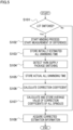
- FIG. 5 is a flowchart of steps of acquisition of estimated correction information.
- FIG. 6(a) is a graph showing an estimated remaining amount of each yarn supply package Ps before time correction coefficients are acquired.
- FIG. 6(b) is a graph showing an estimated remaining amount of the yarn supply package Ps after the time correction coefficients are acquired.
- FIG. 7 is a schematic diagram of an example of various types of information dealt with by the information management unit 110 and how the various types of information are used (which type of information is used in order to acquire which type of information).
- Information put at a starting point of each dotted-line arrow in FIG. 7 is information used for calculation.
- Information put at a termination point (arrow-head side) of each dotted-line arrow in FIG. 7 is acquired based on one or more types of information used for calculation.
- the machine controller 5 starts the winding process at each spindle 9 and measurement of a difference between the initially-estimated all unwinding time and actual all unwinding time of each spindle 9 (S102).
- the lot indicates the unit of production of wound packages Pw, i.e., a plurality of wound packages Pw formed under the same specifications (e.g., processing conditions including the brand and the unwinding speed) at the spindles 9. That is, the lot in this case may be interpreted as a production condition. For example, when the operator makes a predetermined input indicating the switching of the lot into the machine input unit 5a of the machine controller 5, the information management unit 110 determines that the lot has been switched.
- the yarn detection sensor 24 detects the start of supply of the yarn Y.
- the information management unit 110 then performs the reset process based on a detection result of the detection sensor 24 and starts update of the cumulative time (tin).
- the information management unit 110 acquires and stores the initially-estimated all unwinding time of the yarn supply package Ps1 by using only the system values (S103).
- tP WF ⁇ 1000 / V ⁇ F / 10000
- the "1000” of this equation indicates a coefficient for converting the unit of a numerator on the right side of this equation to gram.
- the "10000” of this equation indicates a coefficient for converting the unit of a denominator on the right side of this equation to g/min.
- the unit of tP is minute. Also in equations described later, the "1000" and the "10000" indicate these respective coefficients.
- the information management unit 110 may estimate the remaining time tR based on, e.g., any one of the following equations.
- tR tP ⁇ tin 1
- tR WF ⁇ 1000/ V ⁇ F / 10000 ⁇ tin 1
- the information management unit 110 may estimate a time point (estimated unwinding end time point) at which the unwinding of the yarn Y from the yarn supply package Ps1 ends.
- the information management unit 110 may store a time point (the above-described time point t0) at which the unwinding of the yarn Y from the yarn supply package Ps1 starts and may acquire a time point obtained by adding tP to t0 as the estimated unwinding end time point of the yarn supply package Ps1.
- the yarn detection sensor 24 detects the end of unwinding of the yarn Y from the yarn supply package Ps1 (yarn supply package switching) at one time point (S104) .
- the information management unit 110 stores a value of tin in the detection of the yarn supply package switching (S105). After that, the value of tin is reset to a predetermined initial time by the above-described reset process.
- the information management unit 110 when the unwinding of the yarn Y is temporarily stopped during the winding process (i.e., when a stopping time exists), the information management unit 110 temporarily stops the update of the cumulative time as described above. In other words, when a stopping time exists, the information management unit 110 performs a process of excluding the stopping time from the actual all unwinding time.
- a graph of FIG. 6(a) schematically shows a difference between the initially-estimated all unwinding time and actual all unwinding time of the yarn supply package Ps1.
- the vertical axis of this graph indicates the remaining amount of the yarn Y, and the horizontal axis of this graph indicates the time points.
- the above-described stopping time is assumed not to occur.
- taP is a time point obtained by adding the initially-estimated all unwinding time tP to the time point t0.
- an actual unwinding end time point (the above-described time point ta1) of the yarn supply package Ps1 is a time point obtained by adding the actual all unwinding time (tA) to the time point t0.
- a difference between tP and tA i.e., a difference between the initially-estimated all unwinding time and the actual all unwinding time
- the actual all unwinding time tA is longer than the initially-estimated all unwinding time tP.
- the difference occurs when the actual fineness of the yarn Y in the yarn supply package Ps1 is slightly different from the fineness setting value (F).
- the information management unit 110 calculates each time correction coefficient by using the initially-estimated all unwinding time and the actual all unwinding time (S106).
- Ct the time correction coefficient of the above-described predetermined spindle 9
- Ct is calculated based on the following equation.
- the time correction coefficient (Ct) is a ratio of the actual all unwinding time (tA) to the initially-estimated all unwinding time (tP).
- Ct is a ratio of the actual all unwinding time (tA) to the initially-estimated all unwinding time (tP).
- tA the actual all unwinding time
- tP the initially-estimated all unwinding time
- the information management unit 110 is able to acquire the time obtained by multiplying tP by Ct (this acquired time is identical with the actual all unwinding time tA) as an estimated value of the time from the start to end of unwinding of the yarn Y from the yarn supply package Ps2.
- this acquired time is identical with the actual all unwinding time tA
- an estimated time point at which the unwinding of the yarn Y from the yarn supply package Ps2 ends is substantially identical (see FIG. 6(b) ) with an actual time point at which the unwinding of the yarn Y from the yarn supply package Ps2 ends.
- the information management unit 110 calculates and stores an average value (integrated correction value of the present invention) of the time correction coefficients (S107). After that, by using the averaged time correction coefficient and the system values, the information management unit 110 acquires various types of the corrected estimation information of a yarn supply package Ps from which the yarn Y is unwound at least after the yarn supply package Ps1 (S108).
- the yarn supply package Ps from which the yarn Y is unwound at least after the yarn supply package Ps1 is referred to as the "latter yarn supply package Ps" (second yarn supply package of the present invention).
- the information management unit 110 acquires the corrected estimation information of the spindles 9 of the false-twist texturing machine 1 (i.e., of the yarn supply package retaining portions 20) by using the averaged time correction coefficient.
- the information management unit 110 is able to acquire, as the corrected estimation information, information of corrected estimation time which is an estimated value of the time from the start to end of unwinding of the yarn Y from the latter yarn supply package Ps.
- the corrected estimation time is an estimated value of the time from the start to end of unwinding of the yarn Y from the latter yarn supply package Ps.
- the information management unit 110 may acquire information indicating a time point at which unwinding of the yarn Y from the latter yarn supply package Ps starts, by using a detection result of the yarn detection sensor 24. In this case, by using information of a switching time point and information of the corrected estimation time, the information management unit 110 is able to acquire information of a corrected unwinding end time point at which the unwinding of the yarn Y from the latter yarn supply package Ps ends.
- the information management unit 110 is able to acquire information of corrected remaining time which is the remaining time to the end of unwinding of the yarn Y from the latter yarn supply package Ps.
- the information management unit 110 is able to acquire information of the corrected remaining time by using information of the cumulative time (the above-described tin) regarding the unwinding of the yarn Y from the latter yarn supply package Ps.
- the information of the corrected remaining time is encompassed in the corrected estimation information.
- the information management unit 110 is able to acquire information of a corrected remaining amount which is the remaining amount of the yarn Y in the latter yarn supply package Ps.
- the information of the corrected remaining amount is encompassed in the corrected estimation information.
- WRc WF ⁇ V ⁇ F / 10000 ⁇ tin / 1000 / CtA
- a time correction coefficient (CtA) of this equation is used as a divisor. This is because, the larger the time correction coefficient is, the more an actual pace of unwinding of the yarn Y from each yarn supply package Ps (i.e., actual pace of decrease of weight of each yarn supply package Ps) lags behind the pace originally estimated.
- the information management unit 110 acquires, as the corrected estimation information, at least one of: information of the corrected estimation time; information of the corrected unwinding end time point; information of the corrected remaining time; and information of the corrected remaining amount. These types of information are related to the latter yarn supply package Ps.
- a timing of the end of unwinding of the yarn Y from the latter yarn supply package Ps is estimated based on the corrected estimation information which is acquired by using actual all unwinding time information regarding the actual time from the start to end of the unwinding of the yarn Y from the yarn supply package Ps1, etc. It is therefore possible to accurately estimate a timing of the end of unwinding of the yarn Y from the yarn supply package Ps (end timing).
- the information management unit 110 does not include the stopping time in the actual all unwinding time. It is therefore possible to suppress the decrease in accuracy of estimation as compared to a case where the stopping time is included in the actual all unwinding time.
- the correction values are calculated based on the actual all unwinding time, and the corrected estimation information is acquired by using the correction values. It is therefore possible to acquire various types of accurate information.
- the system values include a setting value of the initial weight WF, a setting value of the fineness, and a setting value of the unwinding speed V.
- the end timing is estimated by using information which can be typically easily acquired as one of the system values.
- the information management unit 110 is able to calculate the initially-estimated all unwinding time by using the system values and to acquire each time correction coefficient calculated by dividing the actual all unwinding time by the initially-estimated all unwinding time. It is therefore possible to accurately estimate the end timing of the latter yarn supply package Ps by multiplying the initially-estimated all unwinding time by the time correction coefficient.
- the accuracy of estimation is further increased by acquiring the integrated correction value with use of plural time correction coefficients.
- the average value of the time correction coefficients is calculated as the integrated correction value. It is therefore possible to acquire the very reliable integrated correction value with a simple calculation.
- the information management unit 110 is configured to acquire, as the corrected estimation information, at least one of: information of the corrected estimation time; information of the corrected unwinding end time point; information of the corrected remaining time; and information of the corrected remaining amount. These types of information are related to the latter yarn supply package Ps. With this arrangement, each type of the acquired corrected estimation information is utilized for various managements (e.g., preparation of a schedule of replacement of the yarn supply package Ps).
- the yarn detection sensor 24 is configured to detect both the actual start and actual end of unwinding, the burden on the operator is reduced as compared to a case where, e.g., the operator makes a predetermined input into the information management unit 110 so as to cause the information management unit 110 to determine that the unwinding has started.
- the information management unit 110 may calculate the above-described corrected remaining amount (WRc) based on, e.g., any one of the following equations.
- WRc WF ⁇ V ⁇ Fc / 10000 ⁇ tin / 1000
- WRc WF ⁇ V ⁇ CfA ⁇ F / 10000 ⁇ tin / 1000
- the information management unit 110 may calculate the corrected estimation time (tPc) of the latter yarn supply package Ps based on, e.g., any one of the following equations.
- tPc WF ⁇ 1000 / V ⁇ Fc / 10000
- tPc WF ⁇ 1000 / V ⁇ CfA ⁇ F / 10000
- the information management unit 110 may calculate the corrected unwinding end time point (tEc) of the latter yarn supply package Ps based on, e.g., any one of the following equations.
- tS is the above-described switching time point.
- tEc tS + tPc
- the information management unit 110 may calculate the above-described corrected remaining time (tRc) based on, e.g., any one of the following equations.
- tRc WRc ⁇ 1000 / V ⁇ Fc / 10000
- tRc tPc ⁇ tin
- the information management unit 110 is configured to acquire, as the corrected estimation information, at least one of: information of the corrected estimation time; information of the corrected unwinding end time point; information of the corrected remaining time; and information of the corrected remaining amount. These types of information are related to the latter yarn supply package Ps.
- the information management unit 110 may be configured to acquire correction values described below, in addition to or instead of the above-described time correction coefficients or the fineness correction coefficients.
- the information management unit 110 may be configured to calculate the corrected unwinding end time point (tEc) of the latter yarn supply package Ps based on, e.g., any of the following equations.
- tEc tS + tPc
- tEc tS + tP + dtPA
- the information management unit 110 may be configured to calculate the corrected remaining time (tRc) of the latter yarn supply package Ps at one reference time point based on, e.g., any one of the following equations.
- tRc tPc ⁇ tin
- tRc tP + dtPA ⁇ tin
- the information management unit 110 may be configured to calculate the corrected remaining amount of the latter yarn supply package Ps at one reference time point based on, e.g., the following equation.
- WRc tRc ⁇ V ⁇ F / 10000 / 1000
- the information management unit 110 is configured to acquire the average value of the correction values as the integrated correction value.
- the disclosure is not limited to this.
- the information management unit 110 may be configured to acquire a median of the correction values as the integrated correction value.
- the information management unit 110 may be configured to acquire the integrated correction value in a different manner.
- the information management unit 110 may be configured to exclude the largest and smallest correction values from a group of the correction values and to acquire an average of a group of the remaining correction values as the integrated correction value.
- the information management unit 110 is configured to acquire the correction values corresponding to the respective spindles 9 each time after the switching of the lot.
- the disclosure is not limited to this.
- the information management unit 110 may additionally acquire a correction value of a new yarn supply package Ps at one or more spindles 9.
- a correction value of the yarn supply package Ps3 (see FIG. 4 ) from which the yarn Y is unwound after the yarn supply package Ps1 may be acquired.
- the yarn supply package Ps3 is equivalent to an additional yarn supply package of the present invention.
- the information management unit 110 may be configured to acquire an update correction value of the above-described predetermined spindle 9 by using at least the additional correction value.
- the information management unit 110 may acquire, as the update correction value, an average value of (i) a correction value which is acquired first (initial correction value) at the above-described predetermined spindle 9 and (ii) the additional correction value which is additionally acquired at the above-described predetermined spindle 9.
- the information management unit 110 may acquire the additional correction value as the updated correction value.
- the information management unit 110 may be configured to acquire the corrected estimation information of a yarn supply package Ps from which the yarn Y is unwound at least after the yarn supply package Ps3, by using the update correction value and the system values. As such, the accuracy of estimation is further increased by acquiring the update correction value according to need and acquiring, with use of the update correction value, the corrected estimation information.
- the information management unit 110 may perform a calculation by taking the additional correction value into consideration. In other words, the information management unit 110 may acquire the integrated correction value by using all correction values regarding the same one lot.
- the information management unit 110 is configured to acquire the correction values of all of the spindles 9 after the switching of the lot.
- the information management unit 110 may be configured to acquire correction values of only some of the spindles 9 and to acquire the integrated correction value based on these correction values.
- the information management unit 110 may be configured to acquire a correction value of only one of the spindles 9.
- the information management unit 110 may be configured to acquire one correction value by using a detection result of one of the yarn detection sensors 24.
- the information management unit 110 may be configured to acquire the corrected estimation information (i.e., corrected estimation information of the yarn supply package retaining portions 20) of the spindles 9 by using this correction value and the system values.
- the information management unit 110 may be configured to acquire a correction value only at a specific spindle 9. Alternatively, the information management unit 110 may be configured to start acquiring the correction values of the spindles 9 and to acquire the corrected estimation information of the spindles 9 by using a correction value which is acquired first among these correction values. In this case, the information management unit 110 may be configured to also acquire the integrated correction value.
- the information management unit 110 is able to immediately start acquiring the corrected estimation information of the yarn supply package Ps2 after acquiring a correction value of the yarn supply package Ps1.
- the yarn supply package Ps2 is also equivalent to the second yarn supply package of the present invention.
- the information management unit 110 is configured to use a single integrated correction value as a correction value shared by all spindles 9.
- the disclosure is not limited to this.
- the information management unit 110 may be configured to acquire a correction value of each spindle 9 and to acquire the corrected estimation information of each spindle 9 by using each different correction value for each spindle 9.
- the information management unit 110 may be configured to acquire the additional correction value and the update correction value which are described above for each of the spindles 9.
- the information management unit 110 is configured to calculate a predetermined correction value by using the system values and the actual all unwinding time and to acquire the corrected estimation information by using the predetermined correction value and the system values.
- the information management unit 110 may be configured to deal with the above-described actual all unwinding time which is not processed, as the corrected estimation information. That is, the actual all unwinding time is dealt with as information of the above-described corrected estimation time.
- the machine controller 5 stores the setting value (initial weight setting value) of the initial weight WF of the yarn Y included in each yarn supply package Ps.
- the machine controller 5 may store a value of the initial length of the yarn Y in the yarn supply package Ps or an initial value of the remaining time, in addition to or instead of the initial weight WF.
- the remaining time and/or the remaining amount at a reference time point may be calculated based on such setting values.
- the information management unit 110 may not acquire information of the fineness of the yarn Y.
- information of the actual all unwinding time is acquired by using the cumulative time information.
- the information of the actual all unwinding time may be acquired by using, instead of the cumulative time information, information of a time point (unwinding start time point) at which the unwinding of the yarn Y from the yarn supply package Ps1 starts and information of a time point (unwinding end time point) at which the unwinding of the yarn Y from the yarn supply package Ps1 ends.
- the information management unit 110 may be configured to acquire information of the unwinding start time point (e.g., the above-described time point t0) of the yarn supply package Ps1 and information of the unwinding end time point of the yarn supply package Ps1 based on a detection result of the yarn detection sensor 24.
- a difference value between the unwinding start time point and the unwinding end time point is basically used instead of the cumulative time.
- Such a process is also encompassed in one process of the present invention, i.e., a process of acquiring the actual all unwinding time information by using a detection result of a detection unit.
- the length of the stopping time is required to be taken into consideration.
- the unwinding speed during the yarn threading is substantially the same as the unwinding speed during the winding process.
- the unwinding speed during the yarn threading may be different from the unwinding speed during the winding process.
- the information management unit 110 may be configured to exclude the time (yarn threading time) required for the yarn threading from the actual all unwinding time. In this regard, the yarn threading is performed after a stopping time exists.
- the winding unit 4 may include an unillustrated contact pressure sensor which is able to detect contact pressure between a wound package Pw and a winding roller 34 (see FIG. 3 ).
- the machine controller 5 may be configured to perform the following determination based on a detection result of each yarn detection sensor 24 and a detection result of each contact pressure sensor. That is, when a yarn Y is unwound from a yarn supply package Ps and a wound package Pw is in contact with a winding roller 34 in one spindle 9, the machine controller 5 may determine that the winding process is performed in this spindle 9. When a yarn Y is unwound from a yarn supply package Ps and a wound package Pw is not in contact with a winding roller 34 in one spindle 9, the machine controller 5 may determine that the yarn threading is performed in this spindle 9.
- the position of each cradle 33 in the winding process may be different from that of each cradle 33 not in the winding process.
- an unillustrated position sensor which is able to detect the position of each cradle 33 may be provided.
- the machine controller 5 may be configured to determine which one of the winding process and the yarn threading is performed, based on a detection result of each yarn detection sensor 24 and a detection result of each position sensor.
- the information management unit 110 may be configured to perform processes described below in a case where a stopping time exists predetermined times or more (hereinafter, such matter will be referred to as "frequently stop(s)") during the unwinding of the yarn Y from the yarn supply package Ps.
- the information management unit 110 may be configured not to acquire a correction value of one yarn supply package Ps which frequently stops.
- the information management unit 110 may be configured to necessarily acquire a correction value of a yarn supply package Ps from which the yarn Y is unwound next to the one yarn supply package Ps in a spindle 9. To the spindle 9, the one yarn supply packages Ps which frequently stops is attached.
- the information management unit 110 is configured to acquire the cumulative time of one of the two package attachment units 21 of each yarn supply package retaining portion 20. To the one of the two package attachment units 21, the yarn supply package Ps from which the yarn Y is unwound at a reference time point is attached. However, the disclosure is not limited to this.
- the information management unit 110 may be configured to acquire the cumulative time of the first attachment unit 22 and the cumulative time of the second attachment unit 23 to be independent from each other. To be more specific, the information management unit 110 may be configured to update only the cumulative time of one of the two package attachment units 21 based on a detection result of the yarn detection sensor 24. To the one of the two package attachment units 21, the yarn supply package Ps from which the yarn Y is unwound is attached.
- the information management unit 110 may reset the cumulative time of one package attachment unit 21 for which the yarn supply package replacement is performed to a predetermined initial time. By doing this, corrected remaining time may be calculated in regard to each of the two package attachment units 21.
- the information management unit 110 may estimate a time point (estimated original yarn disappearance time point) at which all yarn supply packages Ps retained by the yarn supply package retaining portion 20 at one spindle 9 become empty.
- the estimated original yarn disappearance time point is calculated by adding, regardless of whether a node K is formed, the remaining time of the two package attachment units 21 to a reference time point.
- the machine controller 5 may cause the machine output unit 5b to make an output for prompting the operator to replace the yarn supply package Ps at an appropriate timing. For example, the machine controller 5 may determine whether a replacement notification time point has come. The replacement notification time point is before, by a predetermined time, the estimated original yarn disappearance time point of the yarn supply package retaining portion 20 at the one spindle 9. When the replacement notification time point has come, the machine controller 5 may cause the machine output unit 5b to output information indicating that the one spindle 9 requires the replacement of the yarn supply package Ps. Alternatively, this output may be performed by the management output unit 101b of the management device 101.
- the estimated original yarn disappearance time can be calculated as described below. That is, when the yarn supply package Ps from which the yarn Y is unwound is attached to one of the two package attachment units 21, the remaining time of the one package attachment unit 21 is calculatable by using this cumulative time. Furthermore, when a new yarn supply package Ps is attached to the other of the two package attachment units 21, the remaining time of the other package attachment unit 21 can be acquired as a constant. In this regard, when the new yarn supply package Ps is not attached to the other package attachment unit 21, the remaining time of the other package attachment unit 21 can be acquired as zero.
- the estimated original yarn disappearance time point is calculated by adding the remaining time of the one package attachment unit 21 to the remaining time of the other package attachment unit 21.
- the initial amount information is stored in the information management unit 110 as a value shared among all spindles 9 of the false-twist texturing machine 1.
- the spindles 9 may be grouped into plural groups.
- the information management unit 110 may be arranged so that the initial amount information is set for each of these groups.
- the information management unit 110 preferably acquires the time correction coefficients or the fineness correction coefficients.
- the information management unit 110 may be arranged so that the initial amount information is settable for each of the spindle 9. In this case, furthermore, the information management unit 110 may be able to acquire the initial amount information (or information of an initial value of the remaining time) corresponding to each of the yarn supply packages Ps. To be more specific, each time a new yarn supply package Ps is attached to one yarn supply package retaining portion 20, the information management unit 110 may acquire the initial amount information, etc. regarding the new yarn supply package Ps. In this case, as the correction values, the information management unit 110 preferably acquires the time correction coefficients or the fineness correction coefficients.
- the lot indicates the unit of production of wound packages Pw.
- the lot may indicate the unit of production of the yarn supply packages Ps. That is, when the lot of the yarn supply packages Ps is switched, the information management unit 110 may perform a process of acquiring the corrected estimation information.
- a yarn processing facility 100a may include the creel robot 102 which is able to convey one or more yarn supply packages Ps.
- the creel robot 102 is able to: attach the yarn supply package Ps to each package attachment unit 21; and detach the yarn supply package Ps from each package attachment unit 21.
- the creel robot 102 may be controlled by a creel controller 102a which is electrically connected to the management device 101.
- the yarn processing facility 100a may include a wound package conveyance device 103 (see FIG. 10 ) configured to collect and convey each fully-wound package Pw in which the winding process ends.
- the yarn detection sensor 24 including the first detection unit 25 and the second detection unit 26 is configured to detect the start and end of unwinding of the yarn Y from the yarn supply package Ps.
- a yarn supplying unit 2a of a false-twisting texturing machine 1a may include, for each spindle 9a, a detection unit 41 which is different in arrangement from the yarn detection sensor 24.
- the detection unit 41 is equivalent to the detection unit of the present invention.
- the detection unit 41 may include, e.g., a supply sensor 42 and a node part sensor 43.
- the supply sensor 42 is able to detect whether the yarn Y is supplied from the first attachment unit 22 (detect the start of unwinding).
- the node part sensor 43 is able to detect a node K provided to be still at a predetermined position. With this arrangement, when the node K moves from the predetermined position and the node K is no longer detected by the node part sensor 43, it is determined that the yarn supply package switching (the end of unwinding) has occurred. Furthermore, from which one of the attachment units, the first attachment unit 22 or the second attachment unit 23, the yarn Y is supplied in the yarn supply package switching is detectable based on a detection result of the supply sensor 42.
- the node part sensor 43 may be able to detect a moving node K.
- the yarn detection sensor 24 or the detection unit 41 is configured to detect both the start and end of the unwinding of the yarn Y from the yarn supply package Ps.
- an unillustrated tension sensor configured to detect the tension in the yarn Y may be provided for each spindle 9. The start of unwinding of the yarn Y may be detected by this tension sensor.
- the machine controller 5 may determine that the yarn Y starts to be unwound from the yarn supply package Ps. When this input is made, the information management unit 110 may start acquiring the cumulative time and/or may store the unwinding start time point.
- the yarn detection sensor 24 or the detection unit 41 may be configured to detect only the end of unwinding of the yarn Y from the yarn supply package Ps.
- the information management unit 110 is configured to acquire information of the unwinding speed V based on information of the rotation number of the first feed roller 11.
- the machine controller 5 may store information of the rotation number of the second feed roller 16 and information of the ratio of the rotation number of the first feed roller 11 to the rotation number of the second feed roller 16.
- the information management unit 110 may be configured to acquire information of the unwinding speed based on these types of information.
- the information management unit 110 may be configured to acquire information of the weight of the yarn Y which is unwound from the yarn supply package Ps per unit time as the unwinding unit amount information.
- Such information may be input in the machine controller 5 in advance by, e.g., the operator.
- the information management unit 110 may acquire information (for the sake of convenience, this will be referred to as winding start information) of the winding start time point at which the winding of the yarn Y onto the winding bobbin Bw starts.
- the information management unit 110 may acquire information (for the sake of convenience, this will be referred to as winding end information) of at least one of a planned winding end time point, a planned wound amount, and a planned winding time which are described below.
- the planned winding end time point is a planned time point at which the winding of the yarn Y onto the winding bobbin Bw ends.
- the planned wound amount is a wound amount of the yarn Y which is to be wound onto the winding bobbin Bw.
- the planned winding time is the planned time from the current time point to the end of the winding of the yarn Y onto the winding bobbin Bw. For example, by acquiring the winding start information and the winding end information, management described below is performable.
- the information management unit 110 may estimate that a node K will be mixed in a wound package Pw formed by winding the yarn Y onto the winding bobbin Bw.
- the information management unit 110 may estimate that a node K will be mixed in the wound package Pw.
- the information management unit 110 may estimate that a node K will be mixed in the wound package Pw.
- the information management unit 110 may perform at least one of these three estimation methods.
- the information management unit 110 may output information indicating that the node K will be mixed in the wound package Pw.
- the machine controller 5 may control the machine output unit 5b to notify the operator that the node K will be mixed in the wound package Pw.
- the information management unit 110 includes plural machine controllers 5 and the management device 101.
- the information management unit 110 may include a computer device (not illustrated) in addition to the machine controllers 5 and the management device 101.
- the information management unit 110 may include only the machine controllers 5 or the management device 101. In other words, only one of the machine controllers 5 and the management device 101 may be configured to acquire required information.
- the yarn processing facility 100 has plural false-twist texturing machines 1.
- the yarn processing facility 100 may include only one false-twist texturing machine 1.
- the management device 101 may not be provided.
- the false-twist texturing machine 1 is also equivalent to a yarn processing facility of the present invention.
- Each false-twist texturing machine 1 includes plural spindles 9.
- the disclosure is not limited to this. In other words, the number of spindles 9 in the false-twist texturing machine 1 may be one. To put it differently, the number of yarn supply package retaining portions 20 in the yarn supplying unit 2 may be one.
- the present invention may be applied not to the yarn processing facility 100 including the false-twist texturing machine 1 but to another yarn processing facility including a yarn processor.
- the present invention may be applied to a yarn processing facility including an air texturing machine (yarn processor) recited in Japanese Laid-Open Patent Publication No. 2002-088605 .
Landscapes
- Engineering & Computer Science (AREA)
- Quality & Reliability (AREA)
- Filamentary Materials, Packages, And Safety Devices Therefor (AREA)
- Yarns And Mechanical Finishing Of Yarns Or Ropes (AREA)
Abstract
Description
- The present invention relates to a yarn processing facility.
- Patent Literature 1 (Published
Japanese Translation of a PCT application No. 2003-526584 - In the technical field of yarn processing, various improvements have been done to increase the productivity and the quality of products. The inventors of the subject application have continued diligent efforts to develop a yarn processing facility having a novel added value. For example, the present inventors have discussed an idea of significantly improving production management by estimating a timing of running out of a yarn (a timing of the end of unwinding of a yarn) in one yarn supply package from which the yarn is unwound.
- An object of the present invention is to accurately estimate a timing of the end of unwinding of a yarn from a yarn supply package.
- According to a first aspect of the invention, a yarn processing facility includes: a yarn processor including a yarn supplying unit which is able to supply at least one yarn, a processing unit configured to process the at least one yarn supplied from the yarn supplying unit, and a winding unit configured to wind the at least one yarn processed by the processing unit; and an information management unit configured to manage information regarding the yarn processor, the yarn supplying unit including: at least one yarn supply package retaining portion to which yarn supply packages each including a yarn are detachably attached and which is able to uninterruptedly supply each yarn when a terminal portion of a yarn in one yarn supply package among the yarn supply packages is connected to a start end portion of a yarn in a next yarn supply package from which the yarn is to be unwound next to the one yarn supply package; and at least one detection unit which is able to detect at least whether unwinding of a yarn from the one yarn supply package ends, and the information management unit being configured to: acquire actual all unwinding time information regarding actual all unwinding time by using a detection result of the at least one detection unit, the actual all unwinding time being actual time from the start to end of unwinding of a yarn from a predetermined first yarn supply package among the yarn supply packages; and acquire corrected estimation information by using the actual all unwinding time information, the corrected estimation information being usable for estimating a timing of the end of unwinding of a yarn from a second yarn supply package from which the yarn is to be unwound after the first yarn supply package.
- According to this aspect of the present invention, the timing of the end of the unwinding of the yarn from the second yarn supply package is estimated based on the corrected estimation information which is acquired by using the actual all unwinding time information regarding actual time from the start to end of unwinding of a yarn from the first yarn supply package. It is therefore possible to accurately estimate a timing of the end of unwinding of a yarn from a yarn supply package.
- According to a second aspect of the invention, the yarn processing facility of the first aspect is arranged such that the information management unit is further configured to exclude stopping time, in which unwinding of a yarn from the first yarn supply package is temporarily stopped, from the actual all unwinding time when the stopping time exists between the start and end of the unwinding of the yarn from the first yarn supply package.
- Because of sudden events such as yarn breakage, e.g., unwinding of a yarn may be temporarily stopped. In such a case, when the stopping time is included in the actual all unwinding time, the accuracy of the actual all unwinding time is decreased. As a result, the accuracy in estimation of a timing of the end of unwinding of a yarn from the second yarn supply package is decreased. This aspect of the present invention makes it possible to suppress the decrease in accuracy of the estimation as compared to a case where the stopping time is included in the actual all unwinding time.
- According to a third aspect of the invention, the yarn processing facility of the first or second aspect is arranged such that the information management unit is further configured to: store information of at least one system value which is usable for estimating a timing of the end of unwinding of a yarn from the first yarn supply package in advance; calculate at least one predetermined correction value by using the at least one system value and the actual all unwinding time; and acquire the corrected estimation information by using the at least one correction value and the at least one system value.
- When a timing (hereinafter, this timing will be simply referred to as the end timing) of the end of unwinding of a yarn from a yarn supply package is estimated by a calculation, a difference between the calculated end timing and an actual end timing may be large because of a difference between the at least one stored system value and an actual value of one of various parameters which have effects on the actual end timing. According to this aspect of the present invention, the at least one correction value is calculated based on the actual all unwinding time, and the corrected estimation information is acquired by using the at least one correction value. It is therefore possible to acquire various types of accurate information.
- According to a fourth aspect of the invention, the yarn processing facility of the third aspect is arranged such that system values include an initial weight setting value which is a setting value of initial weight of the first yarn supply package, a fineness setting value which is a setting value of fineness of a yarn in the first yarn supply package, and an unwinding speed setting value which is a setting value of unwinding speed at which the yarn is unwound from the first yarn supply package.
- According to this aspect of the present invention, the end timing is estimated by using information which can be typically easily acquired as one of the system values.
- According to a fifth aspect of the invention, the yarn processing facility of the third or fourth aspect is arranged such that the information management unit is further configured to: be able to calculate initially-estimated all unwinding time, which is an estimated value of time from the start to end of unwinding of a yarn from the first yarn supply package, by using the system values; and acquire, as the at least one correction value, a time correction coefficient calculated by dividing the actual all unwinding time by the initially-estimated all unwinding time.
- According to this aspect of the present invention, the end timing of the second yarn supply package is accurately estimated by multiplying the initially-estimated all unwinding time by the time correction coefficient.
- According to a sixth aspect of the invention, the yarn processing facility of the third or fourth aspect is arranged such that the information management unit is further configured to: be able to calculate initially-estimated all unwinding time, which is an estimated value of time from the start to end of unwinding of a yarn from the first yarn supply package, by using the system values; and acquire, as the at least one correction value, a difference value between the actual all unwinding time and the initially-estimated all unwinding time.
- According to this aspect of the present invention, the end timing of the second yarn supply package is accurately estimated on the premise that the initial length of a yarn in the first yarn supply package is substantially identical with the initial length of a yarn in the second yarn supply package.
- According to a seventh aspect of the invention, the yarn processing facility of the fourth aspect is arranged such that the information management unit is further configured to acquire a fineness correction coefficient as the at least one correction value by using the actual all unwinding time, the initial weight setting value, the fineness setting value, and the unwinding speed setting value, and the fineness correction coefficient is usable for correcting the fineness.
- According to this aspect of the present invention, actual fineness of a yarn in the second yarn supply package is accurately estimated by using the fineness correction coefficient. It is therefore possible to accurately estimate a timing of the end of unwinding of the yarn from the second yarn supply package.
- According to an eighth aspect of the invention, the yarn processing facility of any one of the third to seventh aspects is arranged such that the information management unit is further configured to: after acquiring an initial correction value which is the at least one correction value of the first yarn supply package, acquire an additional correction value which is the at least one correction value of an additional yarn supply package which is different from the first yarn supply package and which is retained by the at least one yarn supply package retaining portion; and acquire an update correction value by using at least the additional correction value.
- When the update correction value is acquired by using at least the additional correction value, the following both cases are possible: a case where the update correction value is acquired by a calculation with use of the initial correction value and the additional correction value; and a case where the additional correction value is acquired as the update correction value. According to this aspect of the present invention, the accuracy of estimation is further increased by acquiring the update correction value according to need and acquiring, with use of the update correction value, the corrected estimation information.
- According to a ninth aspect of the invention, the yarn processing facility of any one of the third to eighth aspects is arranged such that the yarn processor is able to simultaneously process yarns, the yarn supplying unit includes yarn supply package retaining portions and detection units provided to correspond to the yarn supply package retaining portions, and the information management unit is further configured to: acquire correction values of the yarn supply package retaining portions by using detection results of the detection units; acquire an integrated correction value by using the correction values; and acquire the corrected estimation information of the yarn supply package retaining portions by using the integrated correction value and the system values.
- According to this aspect of the present invention, the accuracy of estimation is further increased by acquiring the integrated correction value with use of the correction values.
- According to a tenth aspect of the invention, the yarn processing facility of the ninth aspect is arranged such that the integrated correction value is an average value or a median of the correction values.
- According to this aspect of the present invention, the very reliable integrated correction value is acquired with a simple calculation.
- According to an eleventh aspect of the invention, the yarn processing facility of any one of the third to tenth aspects is arranged such that the yarn processor is able to simultaneously process yarns, the yarn supplying unit includes yarn supply package retaining portions and detection units provided to correspond to the yarn supply package retaining portions, the information management unit is further configured to: acquire at least one correction value by using a detection result of one of the detection units; and acquire the corrected estimation information of the yarn supply package retaining portions by using the at least one correction value and the system values.
- When (i) the corrected estimation information is acquired after the detection results of the detection units are acquired and (ii) unwinding of a yarn is stopped for some reason at one of the yarn supply package retaining portions, the start of acquisition of the corrected estimation information may be delayed. According to this aspect of the present invention, when the at least one correction value is acquired, the corrected estimation information of the yarn supply package retaining portions is immediately acquired. It is therefore possible to quickly start the accurate estimation in each of the yarn supply package retaining portions.
- According to a twelfth aspect of the invention, the yarn processing facility of the first or second aspect is arranged such that the information management unit is further configured to deal with the actual all unwinding time as the corrected estimation information.
- When the actual all unwinding time is dealt with as the corrected estimation information, information of the actual all unwinding time is not processed but is used as the corrected estimation information. According to this aspect of the present invention, a timing of the end of unwinding of a yarn from the second yarn supply package is estimated by a simple process on the premise that the initial length of a yarn in the first yarn supply package is substantially identical with the initial length of a yarn in the second yarn supply package.
- According to a thirteenth aspect of the invention, the yarn processing facility of any one of the first to twelfth aspects is arranged such that the information management unit is further configured to acquire, as the corrected estimation information, at least one of: information of corrected estimation time which is an estimated value of time from the start to end of unwinding of a yarn from the second yarn supply package; information of a corrected unwinding end time point which is a time point at which the unwinding of the yarn from the second yarn supply package ends; information of corrected remaining time which is remaining time in which the unwinding of the yarn from the second yarn supply package is possible at a given reference time point; and information of a corrected remaining amount which is a remaining amount of the yarn in the second yarn supply package at the reference time point.
- According to this aspect of the present invention, the acquired corrected estimation information is utilized for various managements (e.g., preparation of a schedule of replacement of a yarn supply package).
- According to a fourteenth aspect of the invention, the yarn processing facility of any one of the first to thirteenth aspects is arranged such that the at least one detection unit is able to detect both the start and end of unwinding of a yarn from the one yarn supply package.
- For example, the information management unit may be configured to determine a timing of the start of the unwinding in such a way that an operator makes a predetermined input in the information management unit. However, this arrangement increases the burden on the operator. According to this aspect of the present invention, because both the actual start and end of the unwinding are detected by the at least one detection unit, the burden on the operator is reduced.
-
-
FIG. 1 is a block diagram of an electric configuration of a yarn processing facility of the present embodiment. -
FIG. 2 is a profile of a false-twist texturing machine. -
FIG. 3 is a schematic diagram of the false-twist texturing machine, expanded along paths of yarns. -
FIG. 4(a) and FIG. 4(b) are graphs each of which shows the relationship between a remaining amount of a yarn in a yarn supply package and time points.FIG. 4(c) is a graph showing the relationship between a wound amount of a yarn onto a winding bobbin and time points. -
FIG. 5 is a flowchart of steps of acquisition of corrected estimation information. -
FIG. 6(a) is a graph showing an estimated remaining amount before a time correction coefficient is acquired.FIG. 6(b) is a graph showing an estimated remaining amount after the time correction coefficient is acquired. -
FIG. 7 is a schematic diagram of an example of various types of information dealt with by an information management unit and how the various types of information are used. -
FIG. 8 is a schematic diagram of an example of various types of information dealt with by an information management unit of a modification and how the various types of information are used. -
FIG. 9 is a schematic diagram of an example of various types of information dealt with by an information management unit of another modification and how the various types of information are used. -
FIG. 10 is a block diagram of an electric configuration of a yarn processing facility of another modification. -
FIG. 11 is a schematic diagram of a false-twist texturing machine of another modification. - The following will describe an embodiment of the present invention. A
yarn processing facility 100 of the present embodiment will be outlined with reference to a block diagram ofFIG. 1 . As shown inFIG. 1 , theyarn processing facility 100 includes false-twist texturing machines 1 (yarn processors of the present invention) and amanagement device 101. The false-twist texturing machines 1 are aligned along, e.g., a predetermined frame longitudinal direction (seeFIG. 2 , etc.). Each false-twist texturing machine 1 is able to perform false twisting of yarns Y (seeFIG. 2 , etc.) made of synthetic fibers such as polyester and nylon (polyamide fibers). Each yarn Y is, e.g., a multi-filament yarn formed of filaments (not illustrated). As described below, each false-twist texturing machine 1 is configured to form wound packages Pw by processing yarns Y supplied from ayarn supplying unit 2 by means of aprocessing unit 3 and winding the yarns Y onto winding bobbins Bw attached to a windingunit 4. Each false-twist texturing machine 1 is controlled by amachine controller 5 that is a computer device mounted on each false-twist texturing machine 1. - The
management device 101 is a host computer used for integrally controlling information acquired bymachine controllers 5. Themanagement device 101 includes amanagement input unit 101a (e.g., a keyboard), amanagement output unit 101b (e.g., a display), and amanagement storage unit 101c (e.g., a hard disk). A combination of themanagement device 101 and themachine controllers 5 is aninformation management unit 110 of the present embodiment. The information dealt with by theinformation management unit 110 will be detailed later. - The overall structure of each false-
twist texturing machine 1 will be described with reference toFIG. 2 andFIG. 3 .FIG. 2 is a profile of each false-twist texturing machine 1.FIG. 3 is a schematic diagram of the false-twist texturing machine 1, expanded along paths of yarns Y (i.e., yarn paths). A direction vertical to the sheet ofFIG. 2 is defined as the above-described frame longitudinal direction, and a left-right direction in the sheet is defined as a frame width direction. A direction orthogonal to both the frame longitudinal direction and the frame width direction is defined as an up-down direction (vertical direction) in which the gravity acts. A direction in which each yarn Y runs is defined as a yarn running direction. The false-twist texturing machine 1 includes ayarn supplying unit 2 provided for supplying yarns Y, aprocessing unit 3 configured to process (false-twist) the yarns Y supplied from the supplyingunit 2, a windingunit 4 configured to wind the yarns Y processed by theprocessing unit 3 onto winding bobbins Bw, and acorresponding machine controller 5. - The
yarn supplying unit 2 includes acreel stand 6 retaining yarn supply packages Ps, and is configured to supply the yarns Y to theprocessing unit 3. Theprocessing unit 3 is configured to unwind the yarns Y from theyarn supplying unit 2 and to process the yarns Y. In theprocessing unit 3, the following members are placed in this order from the upstream side in the yarn running direction:first feed rollers 11; twist-stoppingguides 12;first heaters 13;coolers 14; false-twistingdevices 15;second feed rollers 16;second heaters 17; andthird feed rollers 18. Each of these elements of theprocessing unit 3 is provided for, e.g., each of later-described spindles 9 (seeFIG. 3 ). The windingunit 4 includes plural windingdevices 19. Each windingdevice 19 is configured to wind a yarn Y for which false twisting has been performed by theprocessing unit 3 onto a winding bobbin Bw and to form a wound package Pw. The windingunit 4 is provided withautomatic doffers 10 which correspond to the respective windingdevices 19 and which are configured to replace formed wound packages Pw with empty winding bobbins Bw. - The
machine controller 5 is configured to control theyarn supplying unit 2, theprocessing unit 3, and the windingunit 4. Themachine controller 5 is, e.g., a typical computer device. Themachine controller 5 includes amachine input unit 5a (operation unit of the present invention), amachine output unit 5b, and amachine storage unit 5c (seeFIG. 1 ). Themachine input unit 5a is, e.g., an unillustrated touch panel and/or keyboard and is operable by an operator. Themachine output unit 5b includes, e.g., an unillustrated display and is able to output information. Themachine storage unit 5c is arranged to store various types of information used for controlling theyarn supplying unit 2, processingunit 3, and windingunit 4. Based on the various types of information, themachine controller 5 controls theyarn supplying unit 2, processingunit 3, and windingunit 4. Alternatively, themachine controller 5 may indirectly control theyarn supplying unit 2, processingunit 3, and windingunit 4 through unillustrated controllers (not illustrated) configured to control these members. Themachine controller 5 is electrically connected to themanagement device 101 that is a host computer. Themanagement device 101 is able to perform later-described determinations and/or calculations by using information acquired by themachine controller 5. - The false-
twist texturing machine 1 includes amain frame 7 and a windingbase 8 that are spaced apart from each other in the frame width direction. Themain frame 7 and the windingbase 8 are substantially identical in length in the frame longitudinal direction. Themain frame 7 and the windingbase 8 oppose each other in the frame width direction. The false-twist texturing machine 1 includes units which are termed spans each of which includes a pair of themain frame 7 and the windingbase 8. In one span, each device is placed so that the false twisting is simultaneously performable for the yarns Y running while being aligned in the frame longitudinal direction. In the false-twist texturing machine 1, the spans are placed in a left-right symmetrical manner to the sheet, with a center line C of the frame width direction of themain frame 7 being set as a symmetry axis (main frame 7 is shared between the left span and the right span). The spans are aligned in the frame longitudinal direction. - A group of elements through which a single yarn Y supplied from the
yarn supplying unit 2 passes before reaching the windingunit 4 is termed a spindle. To put it differently, the false-twist texturing machine 1 includes the spindles 9 (seeFIG. 3 ) the number of which is identical with the number of wound packages Pw that can be simultaneously formed. Roughly speaking, thespindles 9 are aligned along the frame longitudinal direction. The inclusion relation is as follows: one false-twist texturing machine 1 includes plural spans, and each of the spans includesplural spindles 9. The false-twist texturing machine 1 is able to false-twist the yarns Y at thespindles 9 to which the yarns Y are threaded. - The structure of the
yarn supplying unit 2 will be described with reference toFIG. 2 andFIG. 3 . The creel stand 6 of theyarn supplying unit 2 includes yarn supply package retaining portions 20 (seeFIG. 3 ) provided to correspond to therespective spindles 9. Each yarn supplypackage retaining portion 20 is arranged so that two yarn supply packages Ps are attachable thereto and detachable therefrom. In other words, each yarn supplypackage retaining portion 20 has twopackage attachment units 21. For the sake of convenience, one of the twopackage attachment units 21 is termed afirst attachment unit 22, and the other of these units is termed asecond attachment unit 23. Each of thefirst attachment unit 22 and thesecond attachment unit 23 is arranged so that one yarn supply package Ps is attachable thereto and detachable therefrom. The attachment and detachment of each yarn supply package Ps to and from a correspondingpackage attachment unit 21 are performed by, e.g., an operator. - Each yarn supply
package retaining portion 20 of theyarn supplying unit 2 is able to uninterruptedly supply a yarn Y in a manner described below. For example, as shown inFIG. 3 , one of the yarn supply packages Ps, i.e., a yarn supply package PsA (one yarn supply package of the present invention) is attached to thefirst attachment unit 22. Furthermore, the other of the yarn supply packages Ps, i.e., a yarn supply package PsB (next yarn supply package of the present invention) is attached to thesecond attachment unit 23. The yarn Y is unwound from the yarn supply package PsA. A terminal portion of the yarn Y in the yarn supply package PsA is tied (connected) to a start end portion of a yarn Y in the yarn supply package PsB. With this arrangement, a node K (yarn connecting portion) is formed between two yarns Y. This makes it possible to uninterruptedly supply the yarn Y from the yarn supply package PsB after the yarn supply package PsA becomes empty. To be more specific, immediately after (i) supply of the yarn Y from the yarn supply package PsA ends and (ii) the yarn supply package PsA becomes empty, the node K is pulled toward the downstream side in the yarn running direction (i.e., toward the winding device 19) so that the yarn Y is unwound from the yarn supply package PsB. In other words, after unwinding of a yarn Y from a yarn supply package Ps attached to onepackage attachment unit 21 ends, unwinding of a yarn Y from the next yarn supply package Ps attached to the otherpackage attachment unit 21 starts. Hereinafter, for the sake of convenience, such a matter is referred to as yarn supply package switching. In this way, the yarn Y is uninterruptedly supplied. Thereafter, the yarn supply package Ps (yarn supplying bobbin Bs) having become empty is replaced with a new yarn supply package Ps by, e.g., the operator. - On the downstream side in the yarn running direction of each yarn supply
package retaining portion 20, a yarn detection sensor 24 (detection unit of the present invention) is provided. Theyarn detection sensor 24 is able to detect which one of the attachment units, i.e., thefirst attachment unit 22 and orsecond attachment unit 23 is supplying the yarn Y. As shown inFIG. 3 , theyarn detection sensor 24 includes afirst detection unit 25 and asecond detection unit 26. Thefirst detection unit 25 is able to detect whether the yarn Y is being supplied from thefirst attachment unit 22. Thesecond detection unit 26 is able to detect whether the yarn Y is being supplied from thesecond attachment unit 23. Each of thefirst detection unit 25 and thesecond detection unit 26 is, e.g., an optical sensor configured to optically detect the yarn Y. For details of theyarn detection sensor 24, seeJapanese Patent No. 5873105 first detection unit 25 and thesecond detection unit 26 may be, e.g., a contact sensor. - The structure of the
processing unit 3 will be described with reference toFIG. 2 andFIG. 3 . The following will describe a part of theprocessing unit 3, which corresponds to onespindle 9. - A
first feed roller 11 is configured to unwind a yarn Y from one yarn supply package Ps attached to theyarn supplying unit 2 and to feed the yarn Y to afirst heater 13. Thefirst feed roller 11 is provided upstream of a twist-stoppingguide 12 in the yarn running direction. The conveyance speed of conveying the yarn Y by thefirst feed roller 11 is substantially identical with an unwinding speed V (seeFIG. 3 ; hereinafter, this may be referred to as just the unwinding speed) at which the yarn Y is unwound from the yarn supply package Ps. In this regard, information indicating a setting value of the conveyance speed of conveying the yarn Y by thefirst feed roller 11 is stored in, e.g., themachine controller 5 in advance. An unillustrated cutter may be provided upstream of thefirst feed roller 11 in the yarn running direction. - In this case, when yarn breakage occurs, the yarn Y is cut by the cutter so that the yarn Y is prevented from being unintentionally wound onto a rotating member such as the
first feed roller 11. - The twist-stopping
guide 12 is provided to prevent twist of the yarn Y from being propagated to the upstream side of the twist-stoppingguide 12 in the yarn running direction. The twist of the yarn Y is formed by a false-twistingdevice 15. The twist-stoppingguide 12 is provided downstream of thefirst feed roller 11 in the yarn running direction and upstream of afirst heater 13 in the yarn running direction. - The
first heater 13 is configured to heat the yarn Y fed from thefirst feed roller 11. Thefirst heater 13 is provided downstream of the twist-stoppingguide 12 in the yarn running direction and upstream of a cooler 14 in the yarn running direction. For the sake of simplicity, thefirst heater 13 of the present embodiment is configured to heat a single yarn Y. However, the disclosure is not limited to this. Thefirst heater 13 may be able to simultaneously heat plural yarns Y. - The cooler 14 is configured to cool the yarn Y heated by the
first heater 13. The cooler 14 is provided downstream of thefirst heater 13 in the yarn running direction and upstream of the false-twistingdevice 15 in the yarn running direction. For the sake of simplicity, the cooler 14 of the present embodiment is configured to cool a single yarn Y. However, the disclosure is not limited to this. The cooler 14 may be able to simultaneously cool plural yarns Y. - The false-twisting
device 15 is configured to twist the yarn Y. The false-twistingdevice 15 is, e.g., a so-called disc-friction false-twisting device. However, the disclosure is not limited to this. The false-twistingdevice 15 is provided downstream of the cooler 14 in the yarn running direction and upstream of asecond feed roller 16 in the yarn running direction. - The
second feed roller 16 is configured to feed the yarn Y processed by the false-twistingdevice 15 to asecond heater 17. The conveyance speed of conveying the yarn Y by thesecond feed roller 16 is higher than the conveyance speed of conveying the yarn Y by thefirst feed roller 11. The yarn Y is therefore drawn between thefirst feed roller 11 and thesecond feed roller 16. In this regard, information indicating a setting value of the conveyance speed of conveying the yarn Y by thesecond feed roller 16 is stored in, e.g., themachine controller 5 in advance. - The
second heater 17 is configured to heat the yarn Y fed from thesecond feed roller 16. Thesecond heater 17 extends along the vertical direction. For the sake of simplicity, thesecond heater 17 of the present embodiment is configured to heat a single yarn Y. However, the disclosure is not limited to this. Thesecond heater 17 may be able to simultaneously heat plural yarns Y. - A
third feed roller 18 is configured to feed the yarn Y heated by thesecond heater 17 to a windingdevice 19. The conveyance speed of conveying the yarn Y by thethird feed roller 18 is lower than the conveyance speed of conveying the yarn Y by thesecond feed roller 16. The yarn Y is therefore relaxed between thesecond feed roller 16 and thethird feed roller 18. In this regard, information indicating a setting value of the conveyance speed of conveying the yarn Y by thethird feed roller 18 is stored in, e.g., themachine controller 5 in advance. - In the
processing unit 3 arranged as described above, the yarn Y drawn between thefirst feed roller 11 and thesecond feed roller 16 is twisted by the false-twistingdevice 15. The twist formed by the false-twistingdevice 15 propagates to the twist-stoppingguide 12, but does not propagate to the upstream side of the twist-stoppingguide 12 in the yarn running direction. The yarn Y which is twisted and drawn is heated by thefirst heater 13 and thermally set. After that, the yarn Y is cooled by the cooler 14. The yarn Y is untwisted on the downstream side of the false-twistingdevice 15 in the yarn running direction. However, each filament is maintained to be wavy in shape on account of the thermal setting described above. Subsequently, the yarn Y false-twisted by the false-twistingdevice 15 is thermally set by thesecond heater 17 while being relaxed between thesecond feed roller 16 and thethird feed roller 18, and then the yarn Y is guided to the downstream side in the yarn running direction. Finally, the yarn Y fed from thethird feed roller 18 is wound onto a winding bobbin Bw by the windingdevice 19. As a result, one wound package Pw is formed. - The structure of the winding
unit 4 will be described with reference toFIG. 2 andFIG. 3 . The windingunit 4 includes (i) the windingdevices 19 configured to wind yarns Y onto winding bobbins Bw and (ii) the automatic doffers 10 (seeFIG. 2 ) provided to correspond to the respective windingdevices 19. One windingdevice 19 belongs to one spindle 9 (seeFIG. 3 ). Each windingdevice 19 includes, e.g., afulcrum guide 31, atraverse unit 32, acradle 33, and a windingroller 34. Thefulcrum guide 31 is a guide which is a fulcrum when a yarn Y is traversed. Thetraverse unit 32 is configured to traverse the yarn Y by means of, e.g., atraverse guide 35 attached to an endless belt driven by a motor in a reciprocating manner. Thecradle 33 is able to support a winding bobbin Bw (wound package Pw) to be rotatable. The windingroller 34 is configured to rotate the wound package Pw and to apply contact pressure to the surface of the wound package Pw. The windingroller 34 is, e.g., rotationally driven by an unillustrated motor while being in contact with the surface of the wound package Pw. With this arrangement, the wound package Pw is rotationally driven by the friction force, and the shape of the wound package Pw is adjusted by the contact pressure applied to the surface of the wound package Pw. Instead of rotationally driving the windingroller 34, the wound package Pw may be directly rotated by an unillustrated motor. - Each
automatic doffer 10 is configured to detach the wound package Pw from the windingdevice 19 and to attach an empty winding bobbin Bw to the windingdevice 19. To put it differently, at the windingunit 4, theautomatic doffer 10 is able to replace a wound package Pw having been formed with an empty winding bobbin Bw. Theautomatic doffer 10 is provided with an unillustrated cutter which is able to cut the yarn Y in the vicinity of the wound package Pw. As the running yarn Y is cut by the cutter, formation of the wound package Pw is finished. After being cut by the cutter, the yarn Y is kept unwound from the yarn supply package Ps and kept supplied toward the windingdevice 19 at a speed which is substantially the same as the speed of winding the yarn Y onto the winding bobbin Bw. Theautomatic doffer 10 includes an unillustrated suction which is able to suck, capture, and retain the running yarn Y supplied to the windingdevice 19, in a period from the finish of the formation of the wound package Pw to start of winding of the yarn Y onto the next winding bobbin Bw. Before the yarn Y is threaded to the next winding bobbin Bw to which the yarn Y is to be wound next, a part of the yarn Y sucked by the suction is sucked and removed. For details of the structure of theautomatic doffer 10, etc., for example, seeJapanese Laid-Open Patent Publication No. H6-212521 - For example, an unillustrated yarn threading device is provided in the vicinity of the winding
device 19. The yarn threading device is configured to thread the yarn Y onto the empty winding bobbin Bw attached to the windingdevice 19. - In the winding
unit 4 structured as described above, the yarn Y which is fed from the above-describedthird feed roller 18 is wound onto the winding bobbin Bw by each windingdevice 19, and the wound package Pw is formed (winding process). As the cutter of theautomatic doffer 10 cuts the yarn Y, the winding process of winding the yarn Y onto the winding bobbin Bw is finished. Almost at the same time, the yarn Y supplied to the windingdevice 19 is sucked and retained by the suction, and the wound package Pw is detached from thecradle 33 by theautomatic doffer 10. Immediately thereafter, theautomatic doffer 10 attaches a new winding bobbin Bw to thecradle 33. Subsequently, the yarn threading device threads the yarn Y to the new winding bobbin Bw. Thereafter, it becomes possible to start winding of the yarn Y onto the new winding bobbin Bw. - The inventors of the subject application conceived of an idea described below, in order to significantly improve production management as compared to known production management. The inventors of the subject application conceived of an idea of providing a means for knowing, at a desired timing, (i) the remaining amount of the yarn Y (yarn remaining amount; hereinafter, this may be referred to as just the remaining amount) after a part of the yarn Y is unwound from the yarn supply package Ps and/or (ii) the time (remaining time; hereinafter, this may be referred to as just the remaining time) in which the yarn Y can be supplied from the yarn supply package Ps. Alternatively, the time from the start to end of unwinding of the yarn Y from the yarn supply package Ps (i.e., to running out of the yarn Y in the yarn supply package Ps) and/or when unwinding of the yarn Y from the yarn supply package Ps ends may be estimated. As such information is known, a timing of running out of the yarn Y in the yarn supply package Ps from which the yarn Y is unwound can be estimated. In the present embodiment, the
information management unit 110 is configured to perform information processing described later in order to accurately estimate a timing of the end of unwinding of the yarn Y from the yarn supply package Ps. In a specific example, theinformation management unit 110 is configured to acquire and manage various types of information regarding matters shown in graphs ofFIG. 4(a) to FIG. 4(c) . Unless otherwise stated, the following explanation deals with only apredetermined spindle 9 among thespindles 9. - Before specifically explaining information acquired by the
information management unit 110, matters shown in the graphs ofFIG. 4(a) to FIG. 4(c) as examples and time points at which the respective matters occur will be described first in order to assist the understanding of the explanation given later. Theinformation management unit 110 is configured to acquire information of at least one of the matters shown in the graphs ofFIG. 4(a) to FIG. 4(c) . (The details will be given later.) Each time point described below is not a time point which is estimated by any means but a time point at which a corresponding matter actually occurs. -
FIG. 4(a) is a graph showing the relationship between the remaining amount (vertical axis) of a yarn Y in each yarn supply package Ps (to be more specific, yarn supply packages Ps1, Ps3) attached to thefirst attachment unit 22 and time points (horizontal axis).FIG. 4(b) is a graph showing the relationship between the remaining amount (vertical axis) of the yarn Y in each yarn supply package Ps (to be more specific, a yarn supply package Ps2) attached to thesecond attachment unit 23 and time points (horizontal axis).FIG. 4(c) is a graph showing the relationship between the wound amount (vertical axis) of a yarn Y onto each winding bobbin Bw (to be more specific, winding bobbins Bw1, Bw2, Bw3, Bw4, Bw5, and Bw6) and time points (horizontal axis). In all of the graphs ofFIG. 4(a) to FIG. 4(c) , a time point t0 at which unwinding of a yarn Y from the yarn supply package Ps1 starts is the origin. In the present embodiment, the weight (initial weight; hereinafter, this may be referred to as just the initial weight) of each yarn supply package Ps in a state in which a yarn Y is not unwound from each yarn supply package Ps at all (i.e., fully-wound yarn supply package Ps) is always WF. - To begin with, before the time point t0, the fully wound yarn supply package Ps1 is attached to the
first attachment unit 22. The weight of the yarn Y in the yarn supply package Ps1 is identical with the initial weight WF. Furthermore, before the time point t0, the fully-wound yarn supply package Ps2 is attached to thesecond attachment unit 23. A terminal portion of the yarn Y in the yarn supply package Ps1 is tied to a start end portion of a yarn Y in the yarn supply package Ps2, and hence a node K is formed. At the time point t0, yarn threading to each element at thespindle 9 starts. Furthermore, at the time point t0, unwinding of the yarn Y from the fully-wound yarn supply package Ps1 starts. At a time point ts1 immediately after the time point t0, the yarn threading to the winding bobbin Bw1 attached to the windingdevice 19 is completed and winding of the yarn Y onto the winding bobbin Bw1 starts. In this regard, after the unwinding of the yarn Y from the yarn supply package Ps1 starts, the yarn Y is sucked and captured by the suction until the yarn threading to the winding bobbin Bw1 is completed. In the present embodiment, the unwinding speed of the yarn Y in the yarn threading is substantially identical with the unwinding speed (the above-described unwinding speed V) in the winding of the yarn Y onto the winding bobbin Bw. A difference between the time point ts1 and the time point t0 is the time from the start to completion of the yarn threading. - The remaining amount (remaining weight) of the yarn Y in the yarn supply package Ps1 decreases and the wound amount (wound weight) of the yarn Y wound on the winding bobbin Bw1 increases over time. At a time point te1, as the cutter of the
automatic doffer 10 cuts the yarn Y, the winding process of winding the yarn Y onto the winding bobbin Bw1 is finished. Therefore, the time point te1 is a winding end time point at which the winding of the yarn Y onto the winding bobbin Bw1 ends (i.e., the formation of the wound package Pw1 ends). The remaining weight of the yarn supply package Ps1 at this time is W1. Onto the winding bobbin Bw1, only the yarn Y supplied from the yarn supply package Ps1 is wound. The cutting of the yarn Y by the cutter, the sucking and capturing of the yarn Y by the suction (i.e., start of sucking and removal of the yarn Y), and the detachment of the winding bobbin Bw1 (wound package Pw1) from thecradle 33 are almost simultaneously done. At a time point ts2 immediately after the time point te1, the attachment of the winding bobbin Bw2 to thecradle 33 by theautomatic doffer 10 is completed and the winding process of winding the yarn Y onto the winding bobbin Bw2 starts (i.e., the winding bobbin replacement is completed). There is a slight time lag tL (seeFIG. 4(c) ) between the winding end time point (time point te1) of the winding bobbin Bw1 and a winding start time point (time point ts2) of the winding bobbin Bw2 onto which the yarn Y is to be wound next to the winding bobbin Bw1. As described above, even when the replacement of the winding bobbin Bw is performed, the yarn Y is unwound from the yarn supply package Ps at the same speed as the speed of winding the yarn Y onto the winding bobbin Bw. Subsequently, the winding process of winding the yarn Y onto the winding bobbin Bw2 (formation of the wound package Pw2) ends at a time point te2. The winding process of winding the yarn Y onto the winding bobbin Bw3 then starts at a time point ts3. - At a time point ta1 (see
FIG. 4(a) ) that is later than the time point ts3, the yarn supply package Ps1 attached to thefirst attachment unit 22 becomes empty. Therefore, the time point ta1 is an unwinding end time point at which the unwinding of the yarn Y from the yarn supply package Ps1 ends. At the same time as the yarn supply package Ps1 becomes empty, at a time point tb1 (=time point ta1), the node K formed as the yarn Y in the yarn supply package Ps1 is tied with the yarn Y in the yarn supply package Ps2 is pulled toward the windingdevice 19. As a result, the yarn Y starts to be unwound from the yarn supply package Ps2 attached to thesecond attachment unit 23. Therefore, the time point tb1 is an unwinding start time point at which the unwinding of the yarn Y from the yarn supply package Ps2 starts (i.e., the yarn Y starts to be unwound) . Thereafter, at a time point te3, the winding process of winding the yarn Y onto the winding bobbin Bw3 (i.e., formation of the wound package Pw3) ends. Onto the winding bobbin Bw3, both the yarn Y unwound from the yarn supply package Ps1 and the yarn Y unwound from the yarn supply package Ps2 are wound. The wound package Pw3 includes the node K. Thereafter, at a time point ts4, the winding process of winding the yarn Y onto the winding bobbin Bw4 starts. At a time point te4, the winding process of winding the yarn Y onto the winding bobbin Bw4 (i.e., formation of a wound package Pw4) ends. Onto the winding bobbin Bw4, only the yarn Y unwound from the yarn supply package Ps2 is wound. - At a time point which is later than the time point ta1 and is before the yarn supply package Ps2 becomes empty (e.g., at a time point ta2), the operator detaches the empty yarn supply package Ps1 from the
first attachment unit 22 and attaches the fully-wound yarn supply package Ps3 to the first attachment unit 22 (yarn supply package replacement). The remaining weight of the yarn supply package Ps3 at this time is the initial weight WF. Thereafter, at a suitable timing, a terminal portion of the yarn Y in the yarn supply package Ps2 is tied with (connected to) a start end portion of a yarn Y in the yarn supply package Ps3 by the operator so that a node K (seeFIG. 3 ) is formed. The operator may manually perform a tying operation (connecting operation). Alternatively, for example, the operator may perform the tying operation by operating an unillustrated portable tying device. - Thereafter, the yarn Y is wound onto the winding bobbin Bw5 from a time point ts5 to a time point te5 (i.e., a wound package Pw5 is formed). At a time point tb2 between the time point ts5 and the time point te5, the yarn supply package Ps2 attached to the
second attachment unit 23 becomes empty. At the same time as the yarn supply package Ps2 becomes empty, at a time point ta3 (= time point tb2), unwinding of the yarn Y from the yarn supply package Ps3 attached to thefirst attachment unit 22 starts. Subsequently, the yarn Y is wound onto a winding bobbin Bw6 from a time point ts6 to a time point te6 (i.e., a wound package Pw6 is formed). - In consideration of the matters above, to begin with, the outline of basic information acquired by the
information management unit 110 in order to perform determinations and/or calculations will be described. As the basic information, for example, theinformation management unit 110 is configured to acquire initial amount information, unwinding unit amount information, and cumulative time information of each yarn supply package Ps. The initial amount information, unwinding unit amount information, and cumulative time information are usable for acquiring estimation information used for performing various managements regarding theyarn processing facility 100. The estimation information indicates at least one of an estimated value of the remaining amount described below, an estimated value of the remaining time described below, an estimated value of all unwinding time described below, and an estimated value of each unwinding end time point described below. The remaining amount indicates an amount of a yarn Y in each yarn supply package Ps attached to eachpackage attachment unit 21 at a given reference time point. The remaining time indicates the time from a reference time point to the end of unwinding of a yarn Y from each yarn supply package Ps from which the yarn Y is unwound. The all unwinding time indicates a total time from the start to end of unwinding of a yarn Y from each yarn supply package Ps which is a target of estimation. Each unwinding end time point indicates a time point at which unwinding of a yarn Y from a yarn supply package Ps, which is a target of estimation, ends. - The
information management unit 110 may be configured to also acquire various types of information (information regarding a start time point and end time point of the winding process, etc.) of each wound package Pw. The details of acquisition of these types of information are omitted. - The initial amount information is information regarding an initial amount (initial weight or initial length) of a yarn Y in each yarn supply package Ps before unwinding of the yarn Y starts. The initial amount information is set in advance in the
machine controller 5 as, e.g., information shared between all yarn supply packages Ps of eachspindle 9 in one false-twist texturing machine 1. To be more specific, in the present embodiment, information indicating the above-described initial weight WF and information indicating the fineness (weight per unit length) of the yarn Y are stored in eachmachine controller 5 as the initial amount information. The unit of the weight of the yarn supply package Ps is, e.g., kilogram. The fineness of the yarn Y is expressed in units of F. The unit of the fineness is, e.g., dtex (decitex). Decitex indicates the weight (gram) of the yarn Y per 10000 meters. The unwinding unit amount information is information regarding an amount of the yarn Y unwound from each yarn supply package Ps per unit time. The unwinding unit amount information is, e.g., information of the above-described unwinding speed V. For the sake of convenience, the unwinding speed V during the winding process is assumed to be substantially constant in the present embodiment. The unit of the unwinding speed is, e.g., m/min. The unwinding unit amount information is set in advance in eachmachine controller 5 as, e.g., information shared between allspindles 9 in one false-twist texturing machine 1. Themachine controller 5 is configured to acquire information of the unwinding speed V based on, e.g., information indicating a setting value of the rotation number of thefirst feed roller 11. The values of the initial weight WF (initial weight setting value), fineness (fineness setting value), and unwinding speed V (unwinding speed setting value) which are set in advance in theinformation management unit 110 are included in system values of the present invention. - The cumulative time information is information regarding a cumulative value (cumulative time: hereinafter, this may be referred to as just the cumulative time) of the time required for unwinding of the yarn Y from each yarn supply package Ps. For the sake of convenience, the cumulative time of each yarn supply package Ps from which the yarn Y is unwound is referred to as tin. The cumulative time information is acquired as described below. To begin with, for example, when the yarn Y starts to be unwound from the above-described yarn supply package Ps1 at the above-described time point t0, the start of unwinding of the yarn Y is detected by the
yarn detection sensor 24. At this time, themachine controller 5 resets tin to a predetermined initial time (reset process). The predetermined initial time is, e.g., 0. Themachine controller 5 may acquire and store information of an unwinding start time point (i.e., time point t0) at which the unwinding of the yarn Y from the yarn supply package Ps1 starts. Thereafter, themachine controller 5 increases tin (updates tin) over time during the unwinding of the yarn Y from the yarn supply package Ps. In this regard, for example, when the unwinding of the yarn Y from the yarn supply package Ps is temporarily stopped because of yarn breakage, etc. (i.e., a stopping time exists), themachine controller 5 temporarily stops the update of tin. In this way, themachine controller 5 acquires, as the cumulative time (tin), only the time in which the unwinding of the yarn Y from each yarn supply package Ps is detected by theyarn detection sensor 24. Themachine controller 5 is able to acquire the cumulative time information regarding one yarn supply package Ps when the yarn Y is unwound from the one yarn supply package Ps. Typically, when the winding process restarts at thespindle 9 in which the unwinding of the yarn Y is temporarily stopped, the yarn threading to each element at thespindle 9 is required. - Based on a detection result of the
yarn detection sensor 24, themachine controller 5 determines whether the yarn supply package switching, i.e., switching of the yarn supply package Ps supplying the yarn Y has occurred during the winding process. For example, inFIG. 4(a) and FIG. 4(b) , the yarn supply package switching is a matter in which (i) the unwinding of the yarn Y from the yarn supply package Ps1 ends (end of unwinding) and (ii) unwinding of the yarn Y from the yarn supply package Ps2 starts. Themachine controller 5 determines that the yarn supply package switching has occurred when the state of theyarn detection sensor 24 is switched from (i) a state of detecting the yarn Y by one of thefirst detection unit 25 and thesecond detection unit 26 to (ii) a state of detecting the yarn Y by the other one of thefirst detection unit 25 and thesecond detection unit 26. When determining that the yarn supply package switching has occurred, themachine controller 5 performs the above-described reset process to reset tin to a predetermined initial time. Information indicating a time point at which the yarn supply package switching has occurred may be acquired and stored by themachine controller 5 as unwinding start time point information of the yarn supply package Ps2. With this arrangement, theyarn detection sensor 24 is able to detect both the start and end of unwinding of the yarn Y from the yarn supply package Ps1. - As described above, the
information management unit 110 is configured to acquire the initial amount information, the unwinding unit amount information, and the cumulative time information as the basic information. - As the explanation regarding the above-described yarn supply package switching, the following will describe information acquired by the
information management unit 110 when one empty yarn supply package Ps is replaced with a new yarn supply package Ps during the winding process. When the yarn supply package Ps attached to onepackage attachment unit 21 is empty, the operator detaches the empty yarn supply package Ps from the onepackage attachment unit 21 and attaches a new yarn supply package Ps to the onepackage attachment unit 21. At this time, the operator associates (inputs attachment information) individual information of the new yarn supply package Ps with individual information of the onepackage attachment unit 21. Thereafter, the operator connects a start end portion of a yarn Y in the new yarn supply package Ps to a terminal portion of a yarn Y in a yarn supply package Ps attached to the otherpackage attachment unit 21, so that a node K is formed. The operator then provides the node K at a predetermined position. Subsequently, the operator inputs, into themachine controller 5, information (this information will be referred to as arrangement information for the sake of convenience) indicating that the node K has been provided at the predetermined position. When such an input is made, themachine controller 5 stores the arrangement information. After that, when the yarn supply package switching has occurred, themachine controller 5 performs the above-described reset process and stores information (this information will be referred to as movement information for the sake of convenience) indicating that the node K has been moved from the predetermined position. - The following will describe an example of steps of acquisition of the detailed estimation information by the
information management unit 110. The estimation information includes both information acquired by using only the system values and information (corrected estimation information) acquired by using the system values and later-described correction values. Roughly speaking, to begin with, theinformation management unit 110 acquires (i) information of the all unwinding time estimated by using only the system values (initially-estimated all unwinding time) and (ii) information of the actual time from the start to end of unwinding of a yarn Y from each yarn supply package Ps (actual all unwinding time). Theinformation management unit 110 then calculates time correction coefficients (correction values) by using the initially-estimated all unwinding time and the actual all unwinding time, and acquires various types of the corrected estimation information by using the time correction coefficients and the system values. - The steps of acquisition described above are detailed with reference to
FIG. 5 to FIG. 7 .FIG. 5 is a flowchart of steps of acquisition of estimated correction information.FIG. 6(a) is a graph showing an estimated remaining amount of each yarn supply package Ps before time correction coefficients are acquired.FIG. 6(b) is a graph showing an estimated remaining amount of the yarn supply package Ps after the time correction coefficients are acquired.FIG. 7 is a schematic diagram of an example of various types of information dealt with by theinformation management unit 110 and how the various types of information are used (which type of information is used in order to acquire which type of information). Information put at a starting point of each dotted-line arrow inFIG. 7 is information used for calculation. Information put at a termination point (arrow-head side) of each dotted-line arrow inFIG. 7 is acquired based on one or more types of information used for calculation. - To begin with, when a lot (described later) used in the
yarn processing facility 100 has been switched (YES in S101), themachine controller 5 starts the winding process at eachspindle 9 and measurement of a difference between the initially-estimated all unwinding time and actual all unwinding time of each spindle 9 (S102). In the present embodiment, the lot indicates the unit of production of wound packages Pw, i.e., a plurality of wound packages Pw formed under the same specifications (e.g., processing conditions including the brand and the unwinding speed) at thespindles 9. That is, the lot in this case may be interpreted as a production condition. For example, when the operator makes a predetermined input indicating the switching of the lot into themachine input unit 5a of themachine controller 5, theinformation management unit 110 determines that the lot has been switched. - When the unwinding of the yarn Y from, e.g., the yarn supply package Ps1 (first yarn supply package of the present invention) at the above-described
predetermined spindle 9 starts, theyarn detection sensor 24 detects the start of supply of the yarn Y. Theinformation management unit 110 then performs the reset process based on a detection result of thedetection sensor 24 and starts update of the cumulative time (tin). When the yarn Y is unwound from the yarn supply package Ps1, theinformation management unit 110 acquires and stores the initially-estimated all unwinding time of the yarn supply package Ps1 by using only the system values (S103). In this regard, when the initially-estimated all unwinding time is tP (seeFIG. 6(a) andFIG. 7 ), tP is calculated based on, e.g., the following equation.

- The "1000" of this equation indicates a coefficient for converting the unit of a numerator on the right side of this equation to gram. The "10000" of this equation indicates a coefficient for converting the unit of a denominator on the right side of this equation to g/min. The unit of tP is minute. Also in equations described later, the "1000" and the "10000" indicate these respective coefficients.
- The
information management unit 110 may acquire further information of the yarn supply package Ps1 by using the system values. For example, when the remaining amount of the yarn Y in the yarn supply package Ps1 at one reference time point is WR while the cumulative time at the one reference time point is tin1, theinformation management unit 110 may estimate the remaining amount WR based on, e.g., the following equation.

- Furthermore, when the remaining time in which the yarn supply package Ps1 can supply the yarn Y at the one reference time point is tR, the
information management unit 110 may estimate the remaining time tR based on, e.g., any one of the following equations.


- The
information management unit 110 may estimate a time point (estimated unwinding end time point) at which the unwinding of the yarn Y from the yarn supply package Ps1 ends. Theinformation management unit 110 may store a time point (the above-described time point t0) at which the unwinding of the yarn Y from the yarn supply package Ps1 starts and may acquire a time point obtained by adding tP to t0 as the estimated unwinding end time point of the yarn supply package Ps1. - The following describes an acquiring method of the actual all unwinding time. After the storing of the initially-estimated all unwinding time, the
yarn detection sensor 24 detects the end of unwinding of the yarn Y from the yarn supply package Ps1 (yarn supply package switching) at one time point (S104) . At this time, as the actual all unwinding time (e.g., tA; seeFIG. 6(a) andFIG. 7 ), theinformation management unit 110 stores a value of tin in the detection of the yarn supply package switching (S105). After that, the value of tin is reset to a predetermined initial time by the above-described reset process. - In this regard, when the unwinding of the yarn Y is temporarily stopped during the winding process (i.e., when a stopping time exists), the
information management unit 110 temporarily stops the update of the cumulative time as described above. In other words, when a stopping time exists, theinformation management unit 110 performs a process of excluding the stopping time from the actual all unwinding time. - As a reference, a graph of
FIG. 6(a) schematically shows a difference between the initially-estimated all unwinding time and actual all unwinding time of the yarn supply package Ps1. The vertical axis of this graph indicates the remaining amount of the yarn Y, and the horizontal axis of this graph indicates the time points. For simplifying the explanation, the above-described stopping time is assumed not to occur. For example, when the estimated unwinding end time point (see taP inFIG. 6(a) ) of the yarn supply package Ps1 is calculated based on the initially-estimated all unwinding time (tP), taP is a time point obtained by adding the initially-estimated all unwinding time tP to the time point t0. Meanwhile, an actual unwinding end time point (the above-described time point ta1) of the yarn supply package Ps1 is a time point obtained by adding the actual all unwinding time (tA) to the time point t0. In this case, a difference between tP and tA (i.e., a difference between the initially-estimated all unwinding time and the actual all unwinding time) is a difference between the estimated unwinding end time point and the actual unwinding end time point. In an example ofFIG. 6(a) , the actual all unwinding time tA is longer than the initially-estimated all unwinding time tP. Such a difference may occur because of various reasons. For example, the difference occurs when the actual fineness of the yarn Y in the yarn supply package Ps1 is slightly different from the fineness setting value (F). - Subsequently, the
information management unit 110 calculates each time correction coefficient by using the initially-estimated all unwinding time and the actual all unwinding time (S106). When the time correction coefficient of the above-describedpredetermined spindle 9 is Ct (seeFIG. 7 ), Ct is calculated based on the following equation.

- The time correction coefficient (Ct) is a ratio of the actual all unwinding time (tA) to the initially-estimated all unwinding time (tP). When Ct is larger than 1, a pace of unwinding the yarn Y from the yarn supply package Ps1 is slower than the pace originally estimated. On the contrary, when Ct is smaller than 1, a pace of unwinding the yarn Y from the yarn supply package Ps1 is faster than the pace originally estimated. For example, by using the time correction coefficient, a timing of the end of unwinding of the yarn Y from the above-described yarn supply package Ps2 is further accurately estimated. To be more specific, the
information management unit 110 is able to acquire the time obtained by multiplying tP by Ct (this acquired time is identical with the actual all unwinding time tA) as an estimated value of the time from the start to end of unwinding of the yarn Y from the yarn supply package Ps2. In this case, an estimated time point at which the unwinding of the yarn Y from the yarn supply package Ps2 ends is substantially identical (seeFIG. 6(b) ) with an actual time point at which the unwinding of the yarn Y from the yarn supply package Ps2 ends. - Subsequently, each time after time correction coefficients of all of the spindles 9 (e.g.,
spindles 9A to 9Z inFIG. 7 ) are acquired, theinformation management unit 110 calculates and stores an average value (integrated correction value of the present invention) of the time correction coefficients (S107). After that, by using the averaged time correction coefficient and the system values, theinformation management unit 110 acquires various types of the corrected estimation information of a yarn supply package Ps from which the yarn Y is unwound at least after the yarn supply package Ps1 (S108). Hereinafter, for the sake of convenience, the yarn supply package Ps from which the yarn Y is unwound at least after the yarn supply package Ps1 is referred to as the "latter yarn supply package Ps" (second yarn supply package of the present invention). Until the lot switches (NO in S101), theinformation management unit 110 acquires the corrected estimation information of thespindles 9 of the false-twist texturing machine 1 (i.e., of the yarn supply package retaining portions 20) by using the averaged time correction coefficient. - The following describes a specific example of the corrected estimation information. In the present embodiment, the
information management unit 110 is able to acquire, as the corrected estimation information, information of corrected estimation time which is an estimated value of the time from the start to end of unwinding of the yarn Y from the latter yarn supply package Ps. For example, when the averaged time correction coefficient is CtA (seeFIG. 7 ) while the corrected estimation time is tPc (seeFIG. 7 ), tPc is calculated based on the following equation.

- The
information management unit 110 may acquire information indicating a time point at which unwinding of the yarn Y from the latter yarn supply package Ps starts, by using a detection result of theyarn detection sensor 24. In this case, by using information of a switching time point and information of the corrected estimation time, theinformation management unit 110 is able to acquire information of a corrected unwinding end time point at which the unwinding of the yarn Y from the latter yarn supply package Ps ends. The information of the corrected unwinding end time point is encompassed in the corrected estimation information. For example, when the switching time point is at tS (seeFIG. 7 ) while the corrected unwinding end time point is at tEc (seeFIG. 7 ), tEc is calculated based on, e.g., any one of the following equations.


- Furthermore, when the yarn Y is unwound from the latter yarn supply package Ps at one reference time point, the
information management unit 110 is able to acquire information of corrected remaining time which is the remaining time to the end of unwinding of the yarn Y from the latter yarn supply package Ps. To be more specific, at the one reference time point, theinformation management unit 110 is able to acquire information of the corrected remaining time by using information of the cumulative time (the above-described tin) regarding the unwinding of the yarn Y from the latter yarn supply package Ps. The information of the corrected remaining time is encompassed in the corrected estimation information. When the corrected remaining time is tRc (seeFIG. 7 ), tRc is calculated based on, e.g., any one of the following equations.


- Furthermore, when the yarn Y is unwound from the latter yarn supply package Ps at the one reference time point, the
information management unit 110 is able to acquire information of a corrected remaining amount which is the remaining amount of the yarn Y in the latter yarn supply package Ps. The information of the corrected remaining amount is encompassed in the corrected estimation information. When the corrected remaining amount is WRc (seeFIG. 7 ), WRc is calculated based on, e.g., the following equation.

- A time correction coefficient (CtA) of this equation is used as a divisor. This is because, the larger the time correction coefficient is, the more an actual pace of unwinding of the yarn Y from each yarn supply package Ps (i.e., actual pace of decrease of weight of each yarn supply package Ps) lags behind the pace originally estimated.
- In this way, the
information management unit 110 acquires, as the corrected estimation information, at least one of: information of the corrected estimation time; information of the corrected unwinding end time point; information of the corrected remaining time; and information of the corrected remaining amount. These types of information are related to the latter yarn supply package Ps. - As described above, a timing of the end of unwinding of the yarn Y from the latter yarn supply package Ps is estimated based on the corrected estimation information which is acquired by using actual all unwinding time information regarding the actual time from the start to end of the unwinding of the yarn Y from the yarn supply package Ps1, etc. It is therefore possible to accurately estimate a timing of the end of unwinding of the yarn Y from the yarn supply package Ps (end timing).
- When a stopping time exists between the start and end of the unwinding of the yarn Y from the yarn supply package Ps1, the
information management unit 110 does not include the stopping time in the actual all unwinding time. It is therefore possible to suppress the decrease in accuracy of estimation as compared to a case where the stopping time is included in the actual all unwinding time. - The correction values are calculated based on the actual all unwinding time, and the corrected estimation information is acquired by using the correction values. It is therefore possible to acquire various types of accurate information.
- The system values include a setting value of the initial weight WF, a setting value of the fineness, and a setting value of the unwinding speed V. In the present embodiment, the end timing is estimated by using information which can be typically easily acquired as one of the system values.
- The
information management unit 110 is able to calculate the initially-estimated all unwinding time by using the system values and to acquire each time correction coefficient calculated by dividing the actual all unwinding time by the initially-estimated all unwinding time. It is therefore possible to accurately estimate the end timing of the latter yarn supply package Ps by multiplying the initially-estimated all unwinding time by the time correction coefficient. - The accuracy of estimation is further increased by acquiring the integrated correction value with use of plural time correction coefficients.
- The average value of the time correction coefficients is calculated as the integrated correction value. It is therefore possible to acquire the very reliable integrated correction value with a simple calculation.
- The
information management unit 110 is configured to acquire, as the corrected estimation information, at least one of: information of the corrected estimation time; information of the corrected unwinding end time point; information of the corrected remaining time; and information of the corrected remaining amount. These types of information are related to the latter yarn supply package Ps. With this arrangement, each type of the acquired corrected estimation information is utilized for various managements (e.g., preparation of a schedule of replacement of the yarn supply package Ps). - Because the
yarn detection sensor 24 is configured to detect both the actual start and actual end of unwinding, the burden on the operator is reduced as compared to a case where, e.g., the operator makes a predetermined input into theinformation management unit 110 so as to cause theinformation management unit 110 to determine that the unwinding has started. - The following will describe modifications of the above-described embodiment. The members identical to those in the embodiment described above will be denoted by the same reference numerals, and the explanations thereof are not repeated.
- (1) In the embodiment above, the
information management unit 110 is configured to acquire, as a correction value, each time correction coefficient (Ct) obtained by dividing the actual all unwinding time (tA) by the initially-estimated all unwinding time (tP). However, the disclosure is not limited to this. For example as described below, theinformation management unit 110 may be configured to calculate (acquire) a fineness correction coefficient as each correction value by using the actual all unwinding time, the initial weight setting value, the fineness setting value, and the unwinding speed setting value. The fineness correction coefficient is provided for correcting the fineness of the yarn Y in the yarn supply package Ps1. When the fineness correction coefficient is Cf (seeFIG. 8 ), Cf is calculated based on the equation described later. The actual fineness of the yarn Y in the latter yarn supply package Ps is accurately estimated by using the fineness correction coefficient. This arrangement makes it possible to accurately estimate a timing of the end of unwinding of the yarn Y from the yarn supply package Ps. In this case, theinformation management unit 110 may be configured to acquire the initially-estimated all unwinding time in advance or may be configured not to acquire the initially-estimated all unwinding time.

- The following describes the equations described in the embodiment above again. These equations are respectively provided for calculating the initially-estimated all unwinding time (tP) and each time correction coefficient (Ct).


- These three equations show that Cf is an inverse of Ct. The
information management unit 110 may be configured to calculate and store an average value (integrated correction value of the present invention) of fineness correction coefficients of all of thespindles 9 after acquiring the fineness correction coefficients. For example, when the averaged fineness correction coefficient is CfA (seeFIG. 8 ) while the fineness after correction (corrected fineness) is Fc (see 8), Fc is calculate based on the following equation.

- When the yarn Y is unwound from the latter yarn supply package Ps at one reference time point, the
information management unit 110 may calculate the above-described corrected remaining amount (WRc) based on, e.g., any one of the following equations.


- Furthermore, the
information management unit 110 may calculate the corrected estimation time (tPc) of the latter yarn supply package Ps based on, e.g., any one of the following equations.

- Furthermore, the
information management unit 110 may calculate the corrected unwinding end time point (tEc) of the latter yarn supply package Ps based on, e.g., any one of the following equations. In this regard, tS is the above-described switching time point.

- Furthermore, when the yarn Y is unwound from the latter yarn supply package Ps at one reference time point, the
information management unit 110 may calculate the above-described corrected remaining time (tRc) based on, e.g., any one of the following equations.


- Also in the present modification, the
information management unit 110 is configured to acquire, as the corrected estimation information, at least one of: information of the corrected estimation time; information of the corrected unwinding end time point; information of the corrected remaining time; and information of the corrected remaining amount. These types of information are related to the latter yarn supply package Ps. - (2) The
information management unit 110 may be configured to acquire correction values described below, in addition to or instead of the above-described time correction coefficients or the fineness correction coefficients. Theinformation management unit 110 may be configured to acquire a difference value between the actual all unwinding time and the initially-estimated all unwinding time as each correction value. To be more specific, when this difference value is dtP (seeFIG. 9 ), theinformation management unit 110 may calculate dtP based on the following equation.

- With this arrangement, the end timing of the latter yarn supply package Ps is accurately estimated on the premise that the initial length of the yarn Y in the above-described yarn supply package Ps1 is substantially identical with the initial length of the yarn Y in the latter yarn supply package Ps. The
information management unit 110 may be configured to calculate and store an average value (integrated correction value of the present invention; see dtPA inFIG. 9 ) of difference values of all of thespindles 9 after acquiring the difference values. Furthermore, the corrected estimation time (tPc) of the latter yarn supply package Ps may be calculated by using the averaged difference value based on the following equation.

- The
information management unit 110 may be configured to calculate the corrected unwinding end time point (tEc) of the latter yarn supply package Ps based on, e.g., any of the following equations.


- The
information management unit 110 may be configured to calculate the corrected remaining time (tRc) of the latter yarn supply package Ps at one reference time point based on, e.g., any one of the following equations.


- The
information management unit 110 may be configured to calculate the corrected remaining amount of the latter yarn supply package Ps at one reference time point based on, e.g., the following equation.

- (3) In the embodiment above, the
information management unit 110 is configured to acquire the average value of the correction values as the integrated correction value. However, the disclosure is not limited to this. For example, theinformation management unit 110 may be configured to acquire a median of the correction values as the integrated correction value. - Alternatively, the
information management unit 110 may be configured to acquire the integrated correction value in a different manner. For example, theinformation management unit 110 may be configured to exclude the largest and smallest correction values from a group of the correction values and to acquire an average of a group of the remaining correction values as the integrated correction value. - (4) In the embodiment above, the
information management unit 110 is configured to acquire the correction values corresponding to therespective spindles 9 each time after the switching of the lot. However, the disclosure is not limited to this. For example, when the operator performs a predetermined operation, theinformation management unit 110 may additionally acquire a correction value of a new yarn supply package Ps at one ormore spindles 9. For example, at the above-describedpredetermined spindle 9, a correction value of the yarn supply package Ps3 (seeFIG. 4 ) from which the yarn Y is unwound after the yarn supply package Ps1 may be acquired. In this case, the yarn supply package Ps3 is equivalent to an additional yarn supply package of the present invention. Furthermore, the correction value of the yarn supply package Ps3 is equivalent to an additional correction value of the present invention. Theinformation management unit 110 may be configured to acquire an update correction value of the above-describedpredetermined spindle 9 by using at least the additional correction value. For example, theinformation management unit 110 may acquire, as the update correction value, an average value of (i) a correction value which is acquired first (initial correction value) at the above-describedpredetermined spindle 9 and (ii) the additional correction value which is additionally acquired at the above-describedpredetermined spindle 9. Alternatively, theinformation management unit 110 may acquire the additional correction value as the updated correction value. Theinformation management unit 110 may be configured to acquire the corrected estimation information of a yarn supply package Ps from which the yarn Y is unwound at least after the yarn supply package Ps3, by using the update correction value and the system values. As such, the accuracy of estimation is further increased by acquiring the update correction value according to need and acquiring, with use of the update correction value, the corrected estimation information. When acquiring the integrated correction value, theinformation management unit 110 may perform a calculation by taking the additional correction value into consideration. In other words, theinformation management unit 110 may acquire the integrated correction value by using all correction values regarding the same one lot. - (5) In the embodiment above, the
information management unit 110 is configured to acquire the correction values of all of thespindles 9 after the switching of the lot. However, the disclosure is not limited to this. Theinformation management unit 110 may be configured to acquire correction values of only some of thespindles 9 and to acquire the integrated correction value based on these correction values. Alternatively, theinformation management unit 110 may be configured to acquire a correction value of only one of thespindles 9. In other words, theinformation management unit 110 may be configured to acquire one correction value by using a detection result of one of theyarn detection sensors 24. Furthermore, theinformation management unit 110 may be configured to acquire the corrected estimation information (i.e., corrected estimation information of the yarn supply package retaining portions 20) of thespindles 9 by using this correction value and the system values. With this arrangement, when one correction value is acquired, the corrected estimation information of the yarn supplypackage retaining portions 20 is immediately acquired. It is therefore possible to quickly start the accurate estimation in each yarn supplypackage retaining portion 20. Theinformation management unit 110 may be configured to acquire a correction value only at aspecific spindle 9. Alternatively, theinformation management unit 110 may be configured to start acquiring the correction values of thespindles 9 and to acquire the corrected estimation information of thespindles 9 by using a correction value which is acquired first among these correction values. In this case, theinformation management unit 110 may be configured to also acquire the integrated correction value. - In the present modification, for example, the
information management unit 110 is able to immediately start acquiring the corrected estimation information of the yarn supply package Ps2 after acquiring a correction value of the yarn supply package Ps1. In this case, the yarn supply package Ps2 is also equivalent to the second yarn supply package of the present invention. - (6) In the embodiment above, the
information management unit 110 is configured to use a single integrated correction value as a correction value shared by allspindles 9. However, the disclosure is not limited to this. For example, theinformation management unit 110 may be configured to acquire a correction value of eachspindle 9 and to acquire the corrected estimation information of eachspindle 9 by using each different correction value for eachspindle 9. In this case, theinformation management unit 110 may be configured to acquire the additional correction value and the update correction value which are described above for each of thespindles 9. - (7) In the embodiment above, the
information management unit 110 is configured to calculate a predetermined correction value by using the system values and the actual all unwinding time and to acquire the corrected estimation information by using the predetermined correction value and the system values. However, the disclosure is not limited to this. Theinformation management unit 110 may be configured to deal with the above-described actual all unwinding time which is not processed, as the corrected estimation information. That is, the actual all unwinding time is dealt with as information of the above-described corrected estimation time. With this arrangement, a timing of the end of the unwinding of the yarn Y from the latter yarn supply package Ps is estimated by a simple process on the premise that the initial length of the yarn Y in the yarn supply package Ps1 is substantially identical with the initial length of the yarn Y in the latter yarn supply package Ps. - (8) In the embodiment above, the
machine controller 5 stores the setting value (initial weight setting value) of the initial weight WF of the yarn Y included in each yarn supply package Ps. However, the disclosure is not limited to this. Themachine controller 5 may store a value of the initial length of the yarn Y in the yarn supply package Ps or an initial value of the remaining time, in addition to or instead of the initial weight WF. The remaining time and/or the remaining amount at a reference time point may be calculated based on such setting values. In the case above, theinformation management unit 110 may not acquire information of the fineness of the yarn Y. - (9) In the embodiment above, information of the actual all unwinding time is acquired by using the cumulative time information. However, the disclosure is not limited to this. The information of the actual all unwinding time may be acquired by using, instead of the cumulative time information, information of a time point (unwinding start time point) at which the unwinding of the yarn Y from the yarn supply package Ps1 starts and information of a time point (unwinding end time point) at which the unwinding of the yarn Y from the yarn supply package Ps1 ends. The
information management unit 110 may be configured to acquire information of the unwinding start time point (e.g., the above-described time point t0) of the yarn supply package Ps1 and information of the unwinding end time point of the yarn supply package Ps1 based on a detection result of theyarn detection sensor 24. In this case, a difference value between the unwinding start time point and the unwinding end time point is basically used instead of the cumulative time. Such a process is also encompassed in one process of the present invention, i.e., a process of acquiring the actual all unwinding time information by using a detection result of a detection unit. When the above-described stopping time exists between the unwinding start time point and the unwinding end time point, the length of the stopping time is required to be taken into consideration. - (10) In the embodiment above, the unwinding speed during the yarn threading is substantially the same as the unwinding speed during the winding process. However, the disclosure is not limited to this. The unwinding speed during the yarn threading may be different from the unwinding speed during the winding process. Irrespective of whether the unwinding speed during the yarn threading is substantially the same as the unwinding speed during the winding process, the
information management unit 110 may be configured to exclude the time (yarn threading time) required for the yarn threading from the actual all unwinding time. In this regard, the yarn threading is performed after a stopping time exists. Such a process is especially effective in a case where, e.g., (i) the unwinding speed during the yarn threading is slower than the unwinding speed during the winding process and (ii) the actual all unwinding time is unlikely to be accurately acquired when the yarn threading time is included in the actual all unwinding time. The following describes an example of the structure provided for determining which one of the yarn threading and the winding process is performed at eachspindle 9. For example, the windingunit 4 may include an unillustrated contact pressure sensor which is able to detect contact pressure between a wound package Pw and a winding roller 34 (seeFIG. 3 ). Themachine controller 5 may be configured to perform the following determination based on a detection result of eachyarn detection sensor 24 and a detection result of each contact pressure sensor. That is, when a yarn Y is unwound from a yarn supply package Ps and a wound package Pw is in contact with a windingroller 34 in onespindle 9, themachine controller 5 may determine that the winding process is performed in thisspindle 9. When a yarn Y is unwound from a yarn supply package Ps and a wound package Pw is not in contact with a windingroller 34 in onespindle 9, themachine controller 5 may determine that the yarn threading is performed in thisspindle 9. Alternatively, for example, the position of eachcradle 33 in the winding process may be different from that of eachcradle 33 not in the winding process. Furthermore, an unillustrated position sensor which is able to detect the position of eachcradle 33 may be provided. In this case, themachine controller 5 may be configured to determine which one of the winding process and the yarn threading is performed, based on a detection result of eachyarn detection sensor 24 and a detection result of each position sensor. - Alternatively, the
information management unit 110 may be configured to perform processes described below in a case where a stopping time exists predetermined times or more (hereinafter, such matter will be referred to as "frequently stop(s)") during the unwinding of the yarn Y from the yarn supply package Ps. For example, theinformation management unit 110 may be configured not to acquire a correction value of one yarn supply package Ps which frequently stops. In this case, for example, theinformation management unit 110 may be configured to necessarily acquire a correction value of a yarn supply package Ps from which the yarn Y is unwound next to the one yarn supply package Ps in aspindle 9. To thespindle 9, the one yarn supply packages Ps which frequently stops is attached. - (11) In the embodiment above, the
information management unit 110 is configured to acquire the cumulative time of one of the twopackage attachment units 21 of each yarn supplypackage retaining portion 20. To the one of the twopackage attachment units 21, the yarn supply package Ps from which the yarn Y is unwound at a reference time point is attached. However, the disclosure is not limited to this. Theinformation management unit 110 may be configured to acquire the cumulative time of thefirst attachment unit 22 and the cumulative time of thesecond attachment unit 23 to be independent from each other. To be more specific, theinformation management unit 110 may be configured to update only the cumulative time of one of the twopackage attachment units 21 based on a detection result of theyarn detection sensor 24. To the one of the twopackage attachment units 21, the yarn supply package Ps from which the yarn Y is unwound is attached. For example, when the above-described attachment information is input in themachine input unit 5a, theinformation management unit 110 may reset the cumulative time of onepackage attachment unit 21 for which the yarn supply package replacement is performed to a predetermined initial time. By doing this, corrected remaining time may be calculated in regard to each of the twopackage attachment units 21. In this case, theinformation management unit 110 may estimate a time point (estimated original yarn disappearance time point) at which all yarn supply packages Ps retained by the yarn supplypackage retaining portion 20 at onespindle 9 become empty. The estimated original yarn disappearance time point is calculated by adding, regardless of whether a node K is formed, the remaining time of the twopackage attachment units 21 to a reference time point. By utilizing information of the estimated original yarn disappearance time point, further advanced control regarding operations such as replacement of yarn supply packages Ps or advanced facility operation management is realized. - For example, when the
information management unit 110 acquires the estimated original yarn disappearance time point, themachine controller 5 may cause themachine output unit 5b to make an output for prompting the operator to replace the yarn supply package Ps at an appropriate timing. For example, themachine controller 5 may determine whether a replacement notification time point has come. The replacement notification time point is before, by a predetermined time, the estimated original yarn disappearance time point of the yarn supplypackage retaining portion 20 at the onespindle 9. When the replacement notification time point has come, themachine controller 5 may cause themachine output unit 5b to output information indicating that the onespindle 9 requires the replacement of the yarn supply package Ps. Alternatively, this output may be performed by themanagement output unit 101b of themanagement device 101. - Even when only the cumulative time of one yarn supply package Ps from which a yarn Y is unwound at a reference time point is calculated, the estimated original yarn disappearance time can be calculated as described below. That is, when the yarn supply package Ps from which the yarn Y is unwound is attached to one of the two
package attachment units 21, the remaining time of the onepackage attachment unit 21 is calculatable by using this cumulative time. Furthermore, when a new yarn supply package Ps is attached to the other of the twopackage attachment units 21, the remaining time of the otherpackage attachment unit 21 can be acquired as a constant. In this regard, when the new yarn supply package Ps is not attached to the otherpackage attachment unit 21, the remaining time of the otherpackage attachment unit 21 can be acquired as zero. The estimated original yarn disappearance time point is calculated by adding the remaining time of the onepackage attachment unit 21 to the remaining time of the otherpackage attachment unit 21. - (12) In the embodiment above, the initial amount information is stored in the
information management unit 110 as a value shared among allspindles 9 of the false-twist texturing machine 1. However, the disclosure is not limited to this. For example, thespindles 9 may be grouped into plural groups. Theinformation management unit 110 may be arranged so that the initial amount information is set for each of these groups. In this case, as the correction values, theinformation management unit 110 preferably acquires the time correction coefficients or the fineness correction coefficients. - Alternatively, the
information management unit 110 may be arranged so that the initial amount information is settable for each of thespindle 9. In this case, furthermore, theinformation management unit 110 may be able to acquire the initial amount information (or information of an initial value of the remaining time) corresponding to each of the yarn supply packages Ps. To be more specific, each time a new yarn supply package Ps is attached to one yarn supplypackage retaining portion 20, theinformation management unit 110 may acquire the initial amount information, etc. regarding the new yarn supply package Ps. In this case, as the correction values, theinformation management unit 110 preferably acquires the time correction coefficients or the fineness correction coefficients. - (13) In the embodiment above, the lot indicates the unit of production of wound packages Pw. However, the disclosure is not limited to this. The lot may indicate the unit of production of the yarn supply packages Ps. That is, when the lot of the yarn supply packages Ps is switched, the
information management unit 110 may perform a process of acquiring the corrected estimation information. - (14) In the embodiment above, the operator performs the replacement of each yarn supply package Ps. However, the disclosure is not limited to this. The replacement of the yarn supply package Ps may be performed by, e.g., a later-described creel robot 102 (see
FIG. 10 ). As shown inFIG. 10 , ayarn processing facility 100a may include thecreel robot 102 which is able to convey one or more yarn supply packages Ps. Thecreel robot 102 is able to: attach the yarn supply package Ps to eachpackage attachment unit 21; and detach the yarn supply package Ps from eachpackage attachment unit 21. Thecreel robot 102 may be controlled by acreel controller 102a which is electrically connected to themanagement device 101. Theyarn processing facility 100a may include a wound package conveyance device 103 (seeFIG. 10 ) configured to collect and convey each fully-wound package Pw in which the winding process ends. - (15) In the embodiment above, the
yarn detection sensor 24 including thefirst detection unit 25 and thesecond detection unit 26 is configured to detect the start and end of unwinding of the yarn Y from the yarn supply package Ps. However, the disclosure is not limited to this. For example, as shown inFIG. 11 , ayarn supplying unit 2a of a false-twistingtexturing machine 1a may include, for eachspindle 9a, adetection unit 41 which is different in arrangement from theyarn detection sensor 24. Being similar to theyarn detection sensor 24, thedetection unit 41 is equivalent to the detection unit of the present invention. Thedetection unit 41 may include, e.g., asupply sensor 42 and anode part sensor 43. Thesupply sensor 42 is able to detect whether the yarn Y is supplied from the first attachment unit 22 (detect the start of unwinding). Thenode part sensor 43 is able to detect a node K provided to be still at a predetermined position. With this arrangement, when the node K moves from the predetermined position and the node K is no longer detected by thenode part sensor 43, it is determined that the yarn supply package switching (the end of unwinding) has occurred. Furthermore, from which one of the attachment units, thefirst attachment unit 22 or thesecond attachment unit 23, the yarn Y is supplied in the yarn supply package switching is detectable based on a detection result of thesupply sensor 42. As such, even when a detection result regarding the node K is used, from which one of the attachment units, thefirst attachment unit 22 or thesecond attachment unit 23, the yarn Y is supplied is reliably detected. Thenode part sensor 43 may be able to detect a moving node K. - (16) In the embodiment above, the
yarn detection sensor 24 or thedetection unit 41 is configured to detect both the start and end of the unwinding of the yarn Y from the yarn supply package Ps. However, the disclosure is not limited to this. For example, an unillustrated tension sensor configured to detect the tension in the yarn Y may be provided for eachspindle 9. The start of unwinding of the yarn Y may be detected by this tension sensor. Alternatively, in accordance with a predetermined input by the operator, themachine controller 5 may determine that the yarn Y starts to be unwound from the yarn supply package Ps. When this input is made, theinformation management unit 110 may start acquiring the cumulative time and/or may store the unwinding start time point. In this case, theyarn detection sensor 24 or thedetection unit 41 may be configured to detect only the end of unwinding of the yarn Y from the yarn supply package Ps. - (17) In the embodiment above, the
information management unit 110 is configured to acquire information of the unwinding speed V based on information of the rotation number of thefirst feed roller 11. However, the disclosure is not limited to this. For example, themachine controller 5 may store information of the rotation number of thesecond feed roller 16 and information of the ratio of the rotation number of thefirst feed roller 11 to the rotation number of thesecond feed roller 16. Theinformation management unit 110 may be configured to acquire information of the unwinding speed based on these types of information. Alternatively, instead of the information of the unwinding speed, theinformation management unit 110 may be configured to acquire information of the weight of the yarn Y which is unwound from the yarn supply package Ps per unit time as the unwinding unit amount information. Such information may be input in themachine controller 5 in advance by, e.g., the operator. - (18) When the yarn Y is wound onto a winding bobbin Bw at one
spindle 9, theinformation management unit 110 may acquire information (for the sake of convenience, this will be referred to as winding start information) of the winding start time point at which the winding of the yarn Y onto the winding bobbin Bw starts. Theinformation management unit 110 may acquire information (for the sake of convenience, this will be referred to as winding end information) of at least one of a planned winding end time point, a planned wound amount, and a planned winding time which are described below. The planned winding end time point is a planned time point at which the winding of the yarn Y onto the winding bobbin Bw ends. The planned wound amount is a wound amount of the yarn Y which is to be wound onto the winding bobbin Bw. The planned winding time is the planned time from the current time point to the end of the winding of the yarn Y onto the winding bobbin Bw. For example, by acquiring the winding start information and the winding end information, management described below is performable. - When the above-described estimated unwinding end time point is between the winding start time point and the planned winding end time point, the
information management unit 110 may estimate that a node K will be mixed in a wound package Pw formed by winding the yarn Y onto the winding bobbin Bw. Alternatively, when the remaining amount of the yarn supply package Ps from which the yarn Y is unwound is smaller than the planned wound amount at the winding start time point, theinformation management unit 110 may estimate that a node K will be mixed in the wound package Pw. Alternatively, when the remaining time of the yarn supply package Ps from which the yarn Y is unwound is shorter than the planned winding time at the winding start time point, theinformation management unit 110 may estimate that a node K will be mixed in the wound package Pw. Theinformation management unit 110 may perform at least one of these three estimation methods. - When determining that a node K will be mixed in the wound package Pw, the
information management unit 110 may output information indicating that the node K will be mixed in the wound package Pw. For example, themachine controller 5 may control themachine output unit 5b to notify the operator that the node K will be mixed in the wound package Pw. - (19) In the embodiment above, the
information management unit 110 includesplural machine controllers 5 and themanagement device 101. However, the disclosure is not limited to this. Theinformation management unit 110 may include a computer device (not illustrated) in addition to themachine controllers 5 and themanagement device 101. Alternatively, theinformation management unit 110 may include only themachine controllers 5 or themanagement device 101. In other words, only one of themachine controllers 5 and themanagement device 101 may be configured to acquire required information. - (20) In the embodiment above, the
yarn processing facility 100 has plural false-twist texturing machines 1. However, the disclosure is not limited to this. Theyarn processing facility 100 may include only one false-twist texturing machine 1. Furthermore, themanagement device 101 may not be provided. In this case, the false-twist texturing machine 1 is also equivalent to a yarn processing facility of the present invention. Each false-twist texturing machine 1 includesplural spindles 9. However, the disclosure is not limited to this. In other words, the number ofspindles 9 in the false-twist texturing machine 1 may be one. To put it differently, the number of yarn supplypackage retaining portions 20 in theyarn supplying unit 2 may be one. - (21) The present invention may be applied not to the
yarn processing facility 100 including the false-twist texturing machine 1 but to another yarn processing facility including a yarn processor. For example, the present invention may be applied to a yarn processing facility including an air texturing machine (yarn processor) recited inJapanese Laid-Open Patent Publication No. 2002-088605
Claims (14)
- A yarn processing facility (100) comprising: a yarn processor (1) including a yarn supplying unit (2) which is able to supply at least one yarn (Y), a processing unit (3) configured to process the at least one yarn (Y) supplied from the yarn supplying unit (2), and a winding unit (4) configured to wind the at least one yarn (Y) processed by the processing unit (3); andan information management unit (110) configured to manage information regarding the yarn processor (1),the yarn supplying unit (2) including:at least one yarn supply package retaining portion (20) to which yarn supply packages (Ps) each including a yarn (Y) are detachably attached and which is able to uninterruptedly supply each yarn (Y) when a terminal portion of a yarn (Y) in one yarn supply package (PsA) among the yarn supply packages (Ps) is connected to a start end portion of a yarn (Y) in a next yarn supply package (PsB) from which the yarn (Y) is to be unwound next to the one yarn supply package (PsA); andat least one detection unit (24, 41) which is able to detect at least whether unwinding of a yarn (Y) from the one yarn supply package (PsA) ends, andthe information management unit (110) being configured to:acquire actual all unwinding time information regarding actual all unwinding time (tA) by using a detection result of the at least one detection unit (24, 41), the actual all unwinding time (tA) being actual time from the start to end of unwinding of a yarn (Y) from a predetermined first yarn supply package (Ps1) among the yarn supply packages (Ps); andacquire corrected estimation information by using the actual all unwinding time information, the corrected estimation information being usable for estimating a timing of the end of unwinding of a yarn (Y) from a second yarn supply package (Ps2) from which the yarn (Y) is to be unwound after the first yarn supply package (Ps1).
- The yarn processing facility (100) according to claim 1, wherein, the information management unit (110) is further configured to exclude stopping time, in which unwinding of a yarn (Y) from the first yarn supply package (Ps1) is temporarily stopped, from the actual all unwinding time (tA) when the stopping time exists between the start and end of the unwinding of the yarn (Y) from the first yarn supply package (Ps1).
- The yarn processing facility (100) according to claim 1 or 2, wherein, the information management unit (110) is further configured to:store information of at least one system value (F, V, WF) which is usable for estimating a timing of the end of unwinding of a yarn (Y) from the first yarn supply package (Ps1) in advance;calculate at least one predetermined correction value (Cf, Ct, dtP) by using the at least one system value (F, V, WF) and the actual all unwinding time (tA); andacquire the corrected estimation information by using the at least one correction value (Cf, Ct, dtP) and the at least one system value (F, V, WF).
- The yarn processing facility (100) according to claim 3, wherein, system values (F, V, WF) include an initial weight setting value (WF) which is a setting value of initial weight (WF) of the first yarn supply package (Ps1), a fineness setting value (F) which is a setting value of fineness (F) of a yarn (Y) in the first yarn supply package (Ps1), and an unwinding speed setting value (V) which is a setting value of unwinding speed (V) at which the yarn (Y) is unwound from the first yarn supply package (Ps1).
- The yarn processing facility (100) according to claim 3 or 4, wherein, the information management unit (110) is further configured to:be able to calculate initially-estimated all unwinding time (tP), which is an estimated value of time from the start to end of unwinding of a yarn (Y) from the first yarn supply package (Ps1), by using the system values (F, V, WF); andacquire, as the at least one correction value (Cf, Ct, dtP), a time correction coefficient (Ct) calculated by dividing the actual all unwinding time (tA) by the initially-estimated all unwinding time (tP).
- The yarn processing facility (100) according to claim 3 or 4, wherein, the information management unit (110) is further configured to:be able to calculate initially-estimated all unwinding time (tP), which is an estimated value of time from the start to end of unwinding of a yarn (Y) from the first yarn supply package (Ps1), by using the system values (F, V, WF); andacquire, as the at least one correction value (Cf, Ct, dtP), a difference value (dtP) between the actual all unwinding time (tA) and the initially-estimated all unwinding time (tP).
- The yarn processing facility (100) according to claim 4, wherein, the information management unit (110) is further configured to acquire a fineness correction coefficient (Cf) as the at least one correction value (Cf, Ct, dtP) by using the actual all unwinding time (tA), the initial weight setting value (WF), the fineness setting value (F), and the unwinding speed setting value (V), and the fineness correction coefficient (Cf) is usable for correcting the fineness (F).
- The yarn processing facility (100) according to any one of claims 3 to 7, wherein, the information management unit (110) is further configured to:after acquiring an initial correction value which is the at least one correction value (Cf, Ct, dtP) of the first yarn supply package (Ps1), acquire an additional correction value which is the at least one correction value (Cf, Ct, dtP) of an additional yarn supply package (Ps3) which is different from the first yarn supply package (Ps1) and which is retained by the at least one yarn supply package retaining portion (20); andacquire an update correction value by using at least the additional correction value.
- The yarn processing facility (100) according to any one of claims 3 to 8, wherein, the yarn processor (1) is able to simultaneously process yarns (Y),the yarn supplying unit (2) includes yarn supply package retaining portions (20) and detection units (24, 41) provided to correspond to the yarn supply package retaining portions (20), andthe information management unit (110) is further configured to: acquire correction values (Cf, Ct, dtP) of the yarn supply package retaining portions (20) by using detection results of the detection units (24, 41);acquire an integrated correction value (CfA, CtA, dtPA) by using the correction values (Cf, Ct, dtP); andacquire the corrected estimation information of the yarn supply package retaining portions (20) by using the integrated correction value (CfA, CtA, dtPA) and the system values (F, V, WF).
- The yarn processing facility (100) according to claim 9, wherein, the integrated correction value (CfA, CtA, dtPA) is an average value or a median of the correction values (Cf, Ct, dtP).
- The yarn processing facility (100) according to any one of claims 3 to 10, wherein, the yarn processor (1) is able to simultaneously process yarns (Y),the yarn supplying unit (2) includes yarn supply package retaining portions (20) and detection units (24, 41) provided to correspond to the yarn supply package retaining portions (20),the information management unit (110) is further configured to: acquire at least one correction value (Cf, Ct, dtP) by using a detection result of one of the detection units (24, 41); andacquire the corrected estimation information of the yarn supply package retaining portions (20) by using the at least one correction value (Cf, Ct, dtP) and the system values (F, V, WF).
- The yarn processing facility (100) according to claim 1 or 2, wherein, the information management unit (110) is further configured to deal with the actual all unwinding time (tA) as the corrected estimation information.
- The yarn processing facility (100) according to any one of claims 1 to 12, wherein, the information management unit (110) is further configured to acquire, as the corrected estimation information, at least one of:information of corrected estimation time (tPc) which is an estimated value of time from the start to end of unwinding of a yarn (Y) from the second yarn supply package (Ps2);information of a corrected unwinding end time point (tEc) which is a time point at which the unwinding of the yarn (Y) from the second yarn supply package (Ps2) ends;information of corrected remaining time (tRc) which is remaining time in which the unwinding of the yarn (Y) from the second yarn supply package (Ps2) is possible at a given reference time point; andinformation of a corrected remaining amount (WRc) which is a remaining amount of the yarn (Y) in the second yarn supply package (Ps2) at the reference time point.
- The yarn processing facility (100) according to any one of claims 1 to 13, wherein, the at least one detection unit (24, 41) is able to detect both the start and end of unwinding of a yarn (Y) from the one yarn supply package (PsA).
Applications Claiming Priority (1)
| Application Number | Priority Date | Filing Date | Title |
|---|---|---|---|
| JP2021198386 | 2021-12-07 |
Publications (2)
| Publication Number | Publication Date |
|---|---|
| EP4194385A1 true EP4194385A1 (en) | 2023-06-14 |
| EP4194385B1 EP4194385B1 (en) | 2026-03-18 |
Family
ID=84359282
Family Applications (1)
| Application Number | Title | Priority Date | Filing Date |
|---|---|---|---|
| EP22208040.0A Active EP4194385B1 (en) | 2021-12-07 | 2022-11-17 | Yarn processing facility |
Country Status (3)
| Country | Link |
|---|---|
| EP (1) | EP4194385B1 (en) |
| CN (1) | CN116238966A (en) |
| TW (1) | TWI904393B (en) |
Families Citing this family (1)
| Publication number | Priority date | Publication date | Assignee | Title |
|---|---|---|---|---|
| CN118014401A (en) * | 2024-03-13 | 2024-05-10 | 北自所(北京)科技发展股份有限公司 | A method, system and device for automatic production scheduling prediction of chemical fiber package products |
Citations (5)
| Publication number | Priority date | Publication date | Assignee | Title |
|---|---|---|---|---|
| JPH06212521A (en) | 1993-01-13 | 1994-08-02 | Murata Mach Ltd | Threading method and apparatus for false twisting machine |
| JP2002088605A (en) | 2000-09-07 | 2002-03-27 | Aiki Seisakusho:Kk | Air processing machine |
| EP1284230A1 (en) * | 2000-04-27 | 2003-02-19 | Teijin Limited | Device and method for fiber processing control |
| JP2003526584A (en) | 1998-10-09 | 2003-09-09 | バルマーク アクチエンゲゼルシヤフト | Method for unwinding yarn continuously |
| JP5873105B2 (en) | 2011-07-06 | 2016-03-01 | ビティエッセエッレ インターナショナル ソチエタ ペル アチオーニ | Apparatus and method for detecting alternation of yarn supply bobbin |
Family Cites Families (3)
| Publication number | Priority date | Publication date | Assignee | Title |
|---|---|---|---|---|
| JP2009023785A (en) * | 2007-07-19 | 2009-02-05 | Murata Mach Ltd | Yarn winding device |
| JP2014227249A (en) * | 2013-05-21 | 2014-12-08 | 村田機械株式会社 | Yarn winder |
| JP6473630B2 (en) * | 2015-02-12 | 2019-02-20 | Tmtマシナリー株式会社 | Yarn winding device |
-
2022
- 2022-11-11 CN CN202211411227.6A patent/CN116238966A/en active Pending
- 2022-11-17 EP EP22208040.0A patent/EP4194385B1/en active Active
- 2022-11-18 TW TW111144211A patent/TWI904393B/en active
Patent Citations (5)
| Publication number | Priority date | Publication date | Assignee | Title |
|---|---|---|---|---|
| JPH06212521A (en) | 1993-01-13 | 1994-08-02 | Murata Mach Ltd | Threading method and apparatus for false twisting machine |
| JP2003526584A (en) | 1998-10-09 | 2003-09-09 | バルマーク アクチエンゲゼルシヤフト | Method for unwinding yarn continuously |
| EP1284230A1 (en) * | 2000-04-27 | 2003-02-19 | Teijin Limited | Device and method for fiber processing control |
| JP2002088605A (en) | 2000-09-07 | 2002-03-27 | Aiki Seisakusho:Kk | Air processing machine |
| JP5873105B2 (en) | 2011-07-06 | 2016-03-01 | ビティエッセエッレ インターナショナル ソチエタ ペル アチオーニ | Apparatus and method for detecting alternation of yarn supply bobbin |
Also Published As
| Publication number | Publication date |
|---|---|
| JP2023084670A (en) | 2023-06-19 |
| CN116238966A (en) | 2023-06-09 |
| EP4194385B1 (en) | 2026-03-18 |
| TWI904393B (en) | 2025-11-11 |
| TW202323174A (en) | 2023-06-16 |
Similar Documents
| Publication | Publication Date | Title |
|---|---|---|
| EP4194385B1 (en) | Yarn processing facility | |
| EP4137430B1 (en) | Yarn processing facility | |
| JP7797266B2 (en) | Yarn processing equipment | |
| EP4292968B1 (en) | Yarn processor | |
| EP4345553A1 (en) | Yarn processing facility | |
| EP4032842B1 (en) | Yarn processing facility | |
| EP4032841A1 (en) | Yarn processing facility | |
| JP7564001B2 (en) | Yarn processing equipment | |
| CN220283137U (en) | Silk thread processing machine | |
| CN106048787A (en) | Method of terminating spinning on open-end spinning machine workstation | |
| JP7844205B2 (en) | Yarn processing equipment |
Legal Events
| Date | Code | Title | Description |
|---|---|---|---|
| PUAI | Public reference made under article 153(3) epc to a published international application that has entered the european phase |
Free format text: ORIGINAL CODE: 0009012 |
|
| STAA | Information on the status of an ep patent application or granted ep patent |
Free format text: STATUS: THE APPLICATION HAS BEEN PUBLISHED |
|
| AK | Designated contracting states |
Kind code of ref document: A1 Designated state(s): AL AT BE BG CH CY CZ DE DK EE ES FI FR GB GR HR HU IE IS IT LI LT LU LV MC ME MK MT NL NO PL PT RO RS SE SI SK SM TR |
|
| STAA | Information on the status of an ep patent application or granted ep patent |
Free format text: STATUS: REQUEST FOR EXAMINATION WAS MADE |
|
| 17P | Request for examination filed |
Effective date: 20231201 |
|
| RBV | Designated contracting states (corrected) |
Designated state(s): AL AT BE BG CH CY CZ DE DK EE ES FI FR GB GR HR HU IE IS IT LI LT LU LV MC ME MK MT NL NO PL PT RO RS SE SI SK SM TR |
|
| GRAP | Despatch of communication of intention to grant a patent |
Free format text: ORIGINAL CODE: EPIDOSNIGR1 |
|
| STAA | Information on the status of an ep patent application or granted ep patent |
Free format text: STATUS: GRANT OF PATENT IS INTENDED |
|
| RIC1 | Information provided on ipc code assigned before grant |
Ipc: B65H 49/12 20060101AFI20251010BHEP Ipc: B65H 63/08 20060101ALI20251010BHEP Ipc: B65H 67/02 20060101ALI20251010BHEP |
|
| INTG | Intention to grant announced |
Effective date: 20251110 |
|
| GRAS | Grant fee paid |
Free format text: ORIGINAL CODE: EPIDOSNIGR3 |
|
| P01 | Opt-out of the competence of the unified patent court (upc) registered |
Free format text: CASE NUMBER: UPC_APP_0019697_4194385/2025 Effective date: 20251230 |
|
| GRAA | (expected) grant |
Free format text: ORIGINAL CODE: 0009210 |
|
| STAA | Information on the status of an ep patent application or granted ep patent |
Free format text: STATUS: THE PATENT HAS BEEN GRANTED |
|
| RAP3 | Party data changed (applicant data changed or rights of an application transferred) |
Owner name: TMT MACHINERY, INC. |
|
| AK | Designated contracting states |
Kind code of ref document: B1 Designated state(s): AL AT BE BG CH CY CZ DE DK EE ES FI FR GB GR HR HU IE IS IT LI LT LU LV MC ME MK MT NL NO PL PT RO RS SE SI SK SM TR |
|
| REG | Reference to a national code |
Ref country code: CH Ref legal event code: F10 Free format text: ST27 STATUS EVENT CODE: U-0-0-F10-F00 (AS PROVIDED BY THE NATIONAL OFFICE) Effective date: 20260318 Ref country code: GB Ref legal event code: FG4D |
|
| REG | Reference to a national code |
Ref country code: IE Ref legal event code: FG4D |
|
| REG | Reference to a national code |
Ref country code: DE Ref legal event code: R096 Ref document number: 602022032492 Country of ref document: DE |
|
| PG25 | Lapsed in a contracting state [announced via postgrant information from national office to epo] |
Ref country code: RS Free format text: LAPSE BECAUSE OF FAILURE TO SUBMIT A TRANSLATION OF THE DESCRIPTION OR TO PAY THE FEE WITHIN THE PRESCRIBED TIME-LIMIT Effective date: 20260618 |
|
| PG25 | Lapsed in a contracting state [announced via postgrant information from national office to epo] |
Ref country code: GR Free format text: LAPSE BECAUSE OF FAILURE TO SUBMIT A TRANSLATION OF THE DESCRIPTION OR TO PAY THE FEE WITHIN THE PRESCRIBED TIME-LIMIT Effective date: 20260619 |
|
| REG | Reference to a national code |
Ref country code: LT Ref legal event code: MG9D |
|
| PG25 | Lapsed in a contracting state [announced via postgrant information from national office to epo] |
Ref country code: LT Free format text: LAPSE BECAUSE OF FAILURE TO SUBMIT A TRANSLATION OF THE DESCRIPTION OR TO PAY THE FEE WITHIN THE PRESCRIBED TIME-LIMIT Effective date: 20260318 |
|
| PG25 | Lapsed in a contracting state [announced via postgrant information from national office to epo] |
Ref country code: NO Free format text: LAPSE BECAUSE OF FAILURE TO SUBMIT A TRANSLATION OF THE DESCRIPTION OR TO PAY THE FEE WITHIN THE PRESCRIBED TIME-LIMIT Effective date: 20260618 |
|
| PG25 | Lapsed in a contracting state [announced via postgrant information from national office to epo] |
Ref country code: FI Free format text: LAPSE BECAUSE OF FAILURE TO SUBMIT A TRANSLATION OF THE DESCRIPTION OR TO PAY THE FEE WITHIN THE PRESCRIBED TIME-LIMIT Effective date: 20260318 Ref country code: SE Free format text: LAPSE BECAUSE OF FAILURE TO SUBMIT A TRANSLATION OF THE DESCRIPTION OR TO PAY THE FEE WITHIN THE PRESCRIBED TIME-LIMIT Effective date: 20260318 |
|
| PG25 | Lapsed in a contracting state [announced via postgrant information from national office to epo] |
Ref country code: HR Free format text: LAPSE BECAUSE OF FAILURE TO SUBMIT A TRANSLATION OF THE DESCRIPTION OR TO PAY THE FEE WITHIN THE PRESCRIBED TIME-LIMIT Effective date: 20260318 |
|
| REG | Reference to a national code |
Ref country code: NL Ref legal event code: MP Effective date: 20260318 |
|
| PG25 | Lapsed in a contracting state [announced via postgrant information from national office to epo] |
Ref country code: LV Free format text: LAPSE BECAUSE OF FAILURE TO SUBMIT A TRANSLATION OF THE DESCRIPTION OR TO PAY THE FEE WITHIN THE PRESCRIBED TIME-LIMIT Effective date: 20260318 |
|
| PG25 | Lapsed in a contracting state [announced via postgrant information from national office to epo] |
Ref country code: BG Free format text: LAPSE BECAUSE OF FAILURE TO SUBMIT A TRANSLATION OF THE DESCRIPTION OR TO PAY THE FEE WITHIN THE PRESCRIBED TIME-LIMIT Effective date: 20260318 |